EP2848494B1 - Child stroller - Google Patents
Child stroller Download PDFInfo
- Publication number
- EP2848494B1 EP2848494B1 EP12876091.5A EP12876091A EP2848494B1 EP 2848494 B1 EP2848494 B1 EP 2848494B1 EP 12876091 A EP12876091 A EP 12876091A EP 2848494 B1 EP2848494 B1 EP 2848494B1
- Authority
- EP
- European Patent Office
- Prior art keywords
- push rod
- wheel bracket
- seat
- rotation shaft
- rear wheel
- Prior art date
- Legal status (The legal status is an assumption and is not a legal conclusion. Google has not performed a legal analysis and makes no representation as to the accuracy of the status listed.)
- Not-in-force
Links
Images


Classifications
-
- B—PERFORMING OPERATIONS; TRANSPORTING
- B62—LAND VEHICLES FOR TRAVELLING OTHERWISE THAN ON RAILS
- B62B—HAND-PROPELLED VEHICLES, e.g. HAND CARTS OR PERAMBULATORS; SLEDGES
- B62B7/00—Carriages for children; Perambulators, e.g. dolls' perambulators
- B62B7/04—Carriages for children; Perambulators, e.g. dolls' perambulators having more than one wheel axis; Steering devices therefor
- B62B7/06—Carriages for children; Perambulators, e.g. dolls' perambulators having more than one wheel axis; Steering devices therefor collapsible or foldable
-
- B—PERFORMING OPERATIONS; TRANSPORTING
- B62—LAND VEHICLES FOR TRAVELLING OTHERWISE THAN ON RAILS
- B62B—HAND-PROPELLED VEHICLES, e.g. HAND CARTS OR PERAMBULATORS; SLEDGES
- B62B9/00—Accessories or details specially adapted for children's carriages or perambulators
- B62B9/20—Handle bars; Handles
- B62B9/203—Handle bars; Handles movable from front end to rear end position
Definitions
- the present invention relates to a baby carriage.
- the main body of an existing baby carriage generally comprises a frame, a seat mounted on the frame and a wheel assembly arranged at the bottom of the frame, and the frame mainly includes a push rod, a front wheel bracket and a rear wheel bracket.
- the frame mainly includes a push rod, a front wheel bracket and a rear wheel bracket.
- the utility model ZL 99226992.X discloses a baby carriage, the baby carriage comprises a front leg, a front wheel assembly, a rear wheel assembly and a push rod, an upper portion of the front leg is connected with a connecting member, an upper portion of the rear leg is also connected with the connecting member, and a lower portion of the push rod is detachably connected with the connecting member.
- the push rod is convertible in the front-rear direction by means of it's rotation relative to the connecting member.
- US 6 116 624 is related to a direction-changing and positioning device for a handle of a baby stroller including: two linkages mounted separately on the handle of the baby stroller and movable upwardly and downwardly relative to the handle; two positioning seats provided respectively on the bottoms of the two linkages and can be moved upwardly by the two linkages, an upper and a lower enraging portion being provided on the upper and the lower ends of each seat; two enraging units provided respectively on both sides of the baby stroller which each is provided with an upper and a lower engaging portion on two suitable upper and lower positions on its corresponding strut, the upper engaging portions being engageable with the upper engaging portions of the positioning seats to secure the positioning seats; wherein, when the linkages are moved upwardly to move the positioning seats upwardly, the handle is pivotable for changing direction, the lower engaging portions of the positioning seats are engaged with the lower engaging portions of the enraging units to secure the positioning seats.
- the stroller thus is convenient and practical in changing direction and positioning.
- US 4 449 732 is related to a reversible foldable push-chair of the umbrella type comprising, on both sides of a hammock carried thereon, a tipping joint core and branches articulated to said core, each branch carrying a wheel, a control pushing arm for controlling sliding and tipping motions and passing through each of the cores, and link means connecting said arm to said branches such that depending on the tipping motion imposed upon the cores by said sliding arm, there is obtained display and locking of the push-chair to a "facing mother" or "look ahead” positions.
- the push-chair is usually applied to transportation of children.
- An object of the invention is to provide a baby carriage which is convertible in direction.
- the push rod has a first working position and a second working position, the push rod can convert from the first working position to the second working position by means of it's rotation relative to the front wheel bracket, and vice versa.
- An upper portion of the push rod is located above the seat at it's back side when the push rod is in the first working position, and the upper portion of the push rod is located above the seat at it's front side when the push rod is in the second working position.
- the push rod When the carriage is pushed in a forward direction, the upper portion of the push rod is positioned above the seat at it's rear side, and when it is required to push the carriage in a reverse direction, the push rod is rotated relative to the front wheel bracket, and the sliding element on the push rod is moved under the traction of the rear wheel bracket, meanwhile, the rear wheel bracket is also rotated relative to the seat rod under the traction of the sliding element, until the push rod is rotated into the second working position such that the push rod is positioned.
- the sliding element is located above the connection location of the push rod and the front wheel bracket, and the sliding element will slide down along the push rod during the conversion of the push rod from the first working position to the second working position.
- the sliding element is a sliding sleeve sheathed on the push rod.
- the sliding element is rotatably connected with the rear wheel bracket by a first rotation shaft
- the front wheel bracket is rotatably connected with the push rod by a second rotation shaft
- the axis of the first rotation shaft and the axis of the second rotation shaft are parallel to each other.
- An embodiment 1 is as shown in fig.s 1-2 , the fig.s 1-2 schematicallyillustrate the structure of a baby carriage which is foldable in single direction, this baby carriage comprises a frame, a seat disposed on the frame, a front wheel assembly 8 and a rear wheel assembly 9 arranged at the bottom of the frame.
- the frame comprises a push rod 1, a front wheel bracket 2 with an upper portion being rotatably connected with the push rod 1 and a lower end being provided with the front wheel assembly 8, a rear wheel bracket 3 with a lower end being provided with the rear wheel assembly 9, and a seat rod 6 with a front portion being connected with the front wheel bracket 2 and a rear portion being rotatably connected with the rear wheel bracket 3, and the seat is located above the seat rod 6.
- the seat is not shown in fig.s because it's configuration and mounting means are well known for a person skilled in the art.
- a backrest rod 7 is connected with the seat rod 6, and the seat is supported by the seat rod 6 and the backrest rod 7.
- the push rod 1 is enabled to be rotated relative to the front wheel bracket 2, such that the push rod 1 has a first working position and a second working position and can be converted between the two positions.
- the first working position of the push rod is as shown in fig.1 , the upper portion of the push rod is located above the seat at it's back side.
- the second working position of the push rod is as shown in fig.2 , the upper portion of the push rod is located above the seat at it's front side.
- front and “rear” herein and throughout the invention are defined according to usual habits of a user, and the left side in the fig.1 refers to a front side, and the right side refers to a rear side.
- a sliding element is slidably disposed on the push rod along the push rod, and the sliding element is rotatably connected with the rear wheel bracket 3.
- the sliding element is a sliding sleeve 4 which is sheathed on the push rod 1, and the sliding sleeve 4 is located above the connection location of the push rod 1 and the front wheel bracket 2.
- the seat rod 6 is rotatably connected with the rear wheel bracket 3 by a third rotation shaft 11, and the axis of the third rotation shaft 11 and the axis of the first rotation shaft 5 are parallel to each other.
- the push rod 1 is in the first working position shown in fig.1 , and the push rod 1 can be converted into the second working position shown in fig.2 , the course of conversion is as follows: the push rod 1 is rotated relative to the front wheel bracket 2 along the direction shown by arrow A of the fig.1 , and under the driving of the sliding sleeve 4, the rear wheel bracket 3 is rotated relative to the seat rod 6 along the direction shown by arrow C of the fig. 1 , meanwhile, the sliding sleeve 4 will be rotated relative to the push rod 1 along the direction shown by arrow B of the fig.1 . As shown in fig.2 , the rear wheel bracket 3 is rotated into a proper position after the conversion of the push rod 1, such that the balance of the baby carriage can be maintained in the reverse state, and also the baby carriage has a nice appearance.
- the locking mechanism may be associated with the connection location of the sliding sleeve 4 or other rods.
- the configuration or operation means of various locking mechanisms have already been well known by a person skilled in the art, thus, the locking mechanism will not be described in more detail in connection with accompanying drawings.
- Fig.s 3 -4 illustrate an embodiment 2 according to the invention
- the difference of the embodiment 2 from the embodiment 1 consists in: the baby carriage is bidirectionally folding.
- a X-shaped bottom bracing 12 is disposed at the bottom of the frame, and the bottom bracing 12 is consisted of two connecting rods which intersect and rotatably connect with each other at the intersection joint, two ends of each connecting rod respectively are correspondingly connected to the front wheel bracket 2 and the rear wheel bracket 3 in opposite sides.
- the bottom bracing 12 will draw together as the baby carriage is folded.
- a user may directly refer to the conversion means described in embodiment 1.
Landscapes
- Engineering & Computer Science (AREA)
- Chemical & Material Sciences (AREA)
- Combustion & Propulsion (AREA)
- Transportation (AREA)
- Mechanical Engineering (AREA)
- Health & Medical Sciences (AREA)
- Public Health (AREA)
- Carriages For Children, Sleds, And Other Hand-Operated Vehicles (AREA)
- Handcart (AREA)
Description
- The present invention relates to a baby carriage.
- The main body of an existing baby carriage generally comprises a frame, a seat mounted on the frame and a wheel assembly arranged at the bottom of the frame, and the frame mainly includes a push rod, a front wheel bracket and a rear wheel bracket. For the convenience of use, currently there is a baby carriage with a convertible push rod.
- For example, the utility model ZL
99226992.X discloses a baby carriage, the baby carriage comprises a front leg, a front wheel assembly, a rear wheel assembly and a push rod, an upper portion of the front leg is connected with a connecting member, an upper portion of the rear leg is also connected with the connecting member, and a lower portion of the push rod is detachably connected with the connecting member. Furthermore, the push rod is convertible in the front-rear direction by means of it's rotation relative to the connecting member. -
US 6 116 624 is related to a direction-changing and positioning device for a handle of a baby stroller including: two linkages mounted separately on the handle of the baby stroller and movable upwardly and downwardly relative to the handle; two positioning seats provided respectively on the bottoms of the two linkages and can be moved upwardly by the two linkages, an upper and a lower enraging portion being provided on the upper and the lower ends of each seat; two enraging units provided respectively on both sides of the baby stroller which each is provided with an upper and a lower engaging portion on two suitable upper and lower positions on its corresponding strut, the upper engaging portions being engageable with the upper engaging portions of the positioning seats to secure the positioning seats; wherein, when the linkages are moved upwardly to move the positioning seats upwardly, the handle is pivotable for changing direction, the lower engaging portions of the positioning seats are engaged with the lower engaging portions of the enraging units to secure the positioning seats. The stroller thus is convenient and practical in changing direction and positioning. -
US 4 449 732 is related to a reversible foldable push-chair of the umbrella type comprising, on both sides of a hammock carried thereon, a tipping joint core and branches articulated to said core, each branch carrying a wheel, a control pushing arm for controlling sliding and tipping motions and passing through each of the cores, and link means connecting said arm to said branches such that depending on the tipping motion imposed upon the cores by said sliding arm, there is obtained display and locking of the push-chair to a "facing mother" or "look ahead" positions. The push-chair is usually applied to transportation of children. - An object of the invention is to provide a baby carriage which is convertible in direction.
- For the foregoing purpose, the invention is defined in
claim 1 and provides a baby carriage comprising a frame, a seat disposed on the frame, and a front wheel assembly and a rear wheel assembly arranged at the bottom of the frame. The frame comprises a push rod, a front wheel bracket with an upper portion being rotatably connected with the push rod and a lower end being provided with the front wheel assembly, a rear wheel bracket with a lower end being provided with the rear wheel assembly, and a seat rod with a front portion being connected with the front wheel bracket and a rear portion being rotatably connected with the rear wheel bracket, and the seat is disposed above the seat rod. A sliding element is disposed on the push rod, which is slidable along the push rod and rotatably connected with the rear wheel bracket. The push rod has a first working position and a second working position, the push rod can convert from the first working position to the second working position by means of it's rotation relative to the front wheel bracket, and vice versa. An upper portion of the push rod is located above the seat at it's back side when the push rod is in the first working position, and the upper portion of the push rod is located above the seat at it's front side when the push rod is in the second working position. When the carriage is pushed in a forward direction, the upper portion of the push rod is positioned above the seat at it's rear side, and when it is required to push the carriage in a reverse direction, the push rod is rotated relative to the front wheel bracket, and the sliding element on the push rod is moved under the traction of the rear wheel bracket, meanwhile, the rear wheel bracket is also rotated relative to the seat rod under the traction of the sliding element, until the push rod is rotated into the second working position such that the push rod is positioned. - The sliding element is located above the connection location of the push rod and the front wheel bracket, and the sliding element will slide down along the push rod during the conversion of the push rod from the first working position to the second working position.
- Preferably, the sliding element is a sliding sleeve sheathed on the push rod.
- Preferably, the sliding element is rotatably connected with the rear wheel bracket by a first rotation shaft, the front wheel bracket is rotatably connected with the push rod by a second rotation shaft, and the axis of the first rotation shaft and the axis of the second rotation shaft are parallel to each other.
- More preferably, the seat rod is rotatably connected with the rear wheel bracket by a third rotation shaft, the axis of the third rotation shaft and the axis of the first rotation shaft are parallel to each other.
- Due to the above technical solution, the present invention has the following advantages as compared with the prior art: in the invention, a baby carriage with a new conception is provided, by means of the rotation of the push rod relative to the front wheel bracket, the sliding element moves relative to the push rod as the push rod rotates and the rear wheel bracket rotates with it, so that the position of the push rod can be changed when the frame is unfolded, and thus the baby carriage is convertible. The baby carriage of the invention has simple configuration, and the folding of the frame will not be hindered by any parts.
-
-
Fig.1 is schematic drawing of a baby carriage according to an embodiment of the invention, wherein the baby carriage is in a forward state; -
Fig.2 is a schematic drawing of the baby carriage offig. 1 in a reverse state; -
Fig.3 is schematic drawing of a baby carriage according to another embodiment of the invention, wherein the baby carriage is in a forward state; -
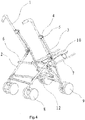
Fig.4 is a schematic drawing of the baby carriage offig. 3 in a reverse state. - 1. a push rod; 2. a front wheel bracket; 3. a rear wheel bracket; 4. a sliding sleeve; 5. a first rotation shaft; 6. a seat rod; 7. a backrest rod; 8. a front wheel assembly; 9. a rear wheel assembly; 10. a second rotation shaft; 11. a third rotation shaft; 12. a bottom bracing.
- The baby carriage according to preferred embodiments of the present invention will be described in more detail hereinafter with reference to the accompanying drawings.
- An
embodiment 1 is as shown infig.s 1-2 , thefig.s 1-2 schematicallyillustrate the structure of a baby carriage which is foldable in single direction, this baby carriage comprises a frame, a seat disposed on the frame, afront wheel assembly 8 and arear wheel assembly 9 arranged at the bottom of the frame. The frame comprises apush rod 1, afront wheel bracket 2 with an upper portion being rotatably connected with thepush rod 1 and a lower end being provided with thefront wheel assembly 8, arear wheel bracket 3 with a lower end being provided with therear wheel assembly 9, and aseat rod 6 with a front portion being connected with thefront wheel bracket 2 and a rear portion being rotatably connected with therear wheel bracket 3, and the seat is located above theseat rod 6. The seat is not shown in fig.s because it's configuration and mounting means are well known for a person skilled in the art. - As shown in
fig.s 2 , usually abackrest rod 7 is connected with theseat rod 6, and the seat is supported by theseat rod 6 and thebackrest rod 7. - The
push rod 1 is enabled to be rotated relative to thefront wheel bracket 2, such that thepush rod 1 has a first working position and a second working position and can be converted between the two positions. The first working position of the push rod is as shown infig.1 , the upper portion of the push rod is located above the seat at it's back side. The second working position of the push rod is as shown infig.2 , the upper portion of the push rod is located above the seat at it's front side. The terms "front" and "rear" herein and throughout the invention are defined according to usual habits of a user, and the left side in thefig.1 refers to a front side, and the right side refers to a rear side. - A sliding element is slidably disposed on the push rod along the push rod, and the sliding element is rotatably connected with the
rear wheel bracket 3. In the preferred embodiment shown infig.s 1 and2 , the sliding element is asliding sleeve 4 which is sheathed on thepush rod 1, and thesliding sleeve 4 is located above the connection location of thepush rod 1 and thefront wheel bracket 2. - Ideally, the
sliding sleeve 4 is rotatably connected with therear wheel bracket 3 by afirst rotation shaft 5, thefront wheel bracket 2 is rotatably connected with thepush rod 1 by asecond rotation shaft 10, and the axis of thefirst rotation shaft 5 and the axis of thesecond rotation shaft 10 are parallel to each other. - Preferably, the
seat rod 6 is rotatably connected with therear wheel bracket 3 by athird rotation shaft 11, and the axis of thethird rotation shaft 11 and the axis of thefirst rotation shaft 5 are parallel to each other. - Generally the
push rod 1 is in the first working position shown infig.1 , and thepush rod 1 can be converted into the second working position shown infig.2 , the course of conversion is as follows: thepush rod 1 is rotated relative to thefront wheel bracket 2 along the direction shown by arrow A of thefig.1 , and under the driving of thesliding sleeve 4, therear wheel bracket 3 is rotated relative to theseat rod 6 along the direction shown by arrow C of thefig. 1 , meanwhile, thesliding sleeve 4 will be rotated relative to thepush rod 1 along the direction shown by arrow B of thefig.1 . As shown infig.2 , therear wheel bracket 3 is rotated into a proper position after the conversion of thepush rod 1, such that the balance of the baby carriage can be maintained in the reverse state, and also the baby carriage has a nice appearance. - For the convenience of the folding of the baby carriage, the front portion of the
seat rod 6 also may be rotatably connected with thefront wheel bracket 2. However, during the conversion of thepush rod 1, it would be best that theseat rod 6 and thefront wheel bracket 2 shall be relatively motionless. - In order to achieve a frame with stable structure in unfolding position (regardless of the state of push rod), preferably the frame is locked by a locking mechanism, the locking mechanism may be associated with the connection location of the
sliding sleeve 4 or other rods. The configuration or operation means of various locking mechanisms have already been well known by a person skilled in the art, thus, the locking mechanism will not be described in more detail in connection with accompanying drawings. -
Fig.s 3 -4 illustrate anembodiment 2 according to the invention, the difference of theembodiment 2 from theembodiment 1 consists in: the baby carriage is bidirectionally folding. A X-shaped bottom bracing 12 is disposed at the bottom of the frame, and the bottom bracing 12 is consisted of two connecting rods which intersect and rotatably connect with each other at the intersection joint, two ends of each connecting rod respectively are correspondingly connected to thefront wheel bracket 2 and therear wheel bracket 3 in opposite sides. The bottom bracing 12 will draw together as the baby carriage is folded. Furthermore, for the conversion means of thepush rod 1 of this embodiment, a user may directly refer to the conversion means described inembodiment 1.
Claims (4)
- A baby carriage, comprising a frame, a seat disposed on the frame, and a front wheel assembly (8) and a rear wheel assembly (9) arranged at the bottom of the frame, the frame comprising a push rod (1), a front wheel bracket (2) with an upper portion being rotatably connected with the push rod (1) and a lower end being provided with the front wheel assembly (8), a rear wheel bracket (3) with a lower end being provided with the rear wheel assembly (9), and a seat rod (6) with a front portion being connected with the front wheel bracket (2) and a rear portion being rotatably connected with the rear wheel bracket (3), the seat being disposed on the seat rod (6); wherein a sliding element (4) is disposed on the push rod (1), which is slidable along the push rod (1) and rotatably connected with the rear wheel bracket (3), the push rod (1) having a first working position and a second working position between which the push rod (1) can convert by means of it's rotation relative to the front wheel bracket (2), an upper portion of the push rod (1) is located above the seat at it's back side when the push rod (1) is in the first working position, and the upper portion of the push rod (1) is located above the seat at it's front side when the push rod (1) is in the second working position, characterized in that the sliding element (4) is located above the connection location of the push rod (1) and the front wheel bracket (2).
- The baby carriage as claimed in claim 1, wherein the sliding element is a sliding sleeve sheathed (4) on the push rod (1).
- The baby carriage as claimed in any one of claims 1-2, wherein the sliding element (4) is rotatably connected with the rear wheel bracket (3) by a first rotation shaft (5), the front wheel bracket (2) is rotatably connected with the push rod (1) by a second rotation shaft (10), and the axis of the first rotation shaft (5) and the axis of the second rotation shaft (10) being parallel to each other.
- The baby carriage as claimed in claim 3, wherein the seat rod (6) is rotatably connected with the rear wheel bracket (3) by a third rotation shaft (11), the axis of the third rotation shaft (11) and the axis of the first rotation shaft (5) being parallel to each other.
Applications Claiming Priority (2)
| Application Number | Priority Date | Filing Date | Title |
|---|---|---|---|
| CN201210141583.0A CN103386999B (en) | 2012-05-09 | 2012-05-09 | Stroller |
| PCT/CN2012/084909 WO2013166818A1 (en) | 2012-05-09 | 2012-11-20 | Child stroller |
Publications (3)
| Publication Number | Publication Date |
|---|---|
| EP2848494A1 EP2848494A1 (en) | 2015-03-18 |
| EP2848494A4 EP2848494A4 (en) | 2016-01-27 |
| EP2848494B1 true EP2848494B1 (en) | 2017-05-24 |
Family
ID=49531459
Family Applications (1)
| Application Number | Title | Priority Date | Filing Date |
|---|---|---|---|
| EP12876091.5A Not-in-force EP2848494B1 (en) | 2012-05-09 | 2012-11-20 | Child stroller |
Country Status (4)
| Country | Link |
|---|---|
| US (1) | US9168939B2 (en) |
| EP (1) | EP2848494B1 (en) |
| CN (1) | CN103386999B (en) |
| WO (1) | WO2013166818A1 (en) |
Families Citing this family (13)
| Publication number | Priority date | Publication date | Assignee | Title |
|---|---|---|---|---|
| ITVR20110226A1 (en) * | 2011-12-20 | 2013-06-21 | Inglesina Baby Spa | FOLDABLE FRAME FOR STROLLERS, WHEELCHAIRS AND THE LIKE |
| CN102923174B (en) * | 2012-10-31 | 2015-10-21 | 好孩子儿童用品有限公司 | toddler stroller |
| GB2516906A (en) * | 2013-08-06 | 2015-02-11 | Mamas & Papas Holdings Ltd | Child support apparatus |
| CN103707912A (en) * | 2013-12-17 | 2014-04-09 | 好孩子儿童用品有限公司 | Stroller allowing reversing |
| CN104943724B (en) * | 2014-03-31 | 2017-08-08 | 明门(中国)幼童用品有限公司 | vehicle frame |
| CN205273564U (en) * | 2015-11-10 | 2016-06-01 | 好孩子儿童用品有限公司 | Child stroller |
| US10252738B2 (en) * | 2016-06-01 | 2019-04-09 | Greg Diep | Stroller pulling handle system |
| CN106515832B (en) * | 2016-11-25 | 2018-10-19 | 好孩子儿童用品有限公司 | Children trolley |
| CN106945709A (en) * | 2017-05-07 | 2017-07-14 | 昆山曼禾儿童用品设计有限公司 | A kind of novel folding doll carriage push rod direction-changing mechanism |
| CN107697142B (en) * | 2017-08-29 | 2024-06-04 | 好孩子儿童用品有限公司 | Strollers |
| CN110843899B (en) * | 2019-12-13 | 2024-09-10 | 太仓新奇乐婴儿用品有限公司 | Push rod front-back reversing structure for baby carriage |
| CN113085988B (en) * | 2019-12-23 | 2023-06-20 | 明门瑞士股份有限公司 | baby carriage |
| CN112678062B (en) * | 2020-12-14 | 2022-05-03 | 好孩子儿童用品有限公司 | Children's barrow |
Family Cites Families (18)
| Publication number | Priority date | Publication date | Assignee | Title |
|---|---|---|---|---|
| IT7420617U1 (en) * | 1974-01-25 | 1975-07-25 | Perego Pines Spa | Baby stroller, easily foldable and carryable on the arm |
| JPS5444916Y2 (en) * | 1976-06-23 | 1979-12-24 | ||
| US4449732A (en) * | 1981-02-13 | 1984-05-22 | Ampafrance S.A. | Reversible foldable push-chair for children |
| GB9313227D0 (en) * | 1993-06-26 | 1993-08-11 | Britax Restmor Ltd | Pushchair |
| US6116624A (en) * | 1998-04-01 | 2000-09-12 | Hu; Stephen | Direction-changing and positioning device for the handle of a baby stroller |
| CN2432115Y (en) * | 2000-07-05 | 2001-05-30 | 好孩子集团公司 | Reversible umbrella handle handcart |
| US6508605B1 (en) * | 2001-09-25 | 2003-01-21 | Pao-Hsien Cheng | Direction changing device for a stroller handle |
| GB2385301B (en) * | 2002-02-13 | 2004-05-19 | Red Lan | Foldable stroller |
| TWM264187U (en) * | 2004-10-05 | 2005-05-11 | Link Treasure Ltd | Brake driving structure for direction-changeable baby stroller |
| JP4726213B2 (en) * | 2005-09-22 | 2011-07-20 | ピジョン株式会社 | stroller |
| CN201338649Y (en) * | 2008-12-12 | 2009-11-04 | 昆山华童幼儿用品有限公司 | Infant wheelbarrow capable of using handles thereof in bi-direction |
| US8210563B2 (en) * | 2008-12-19 | 2012-07-03 | Graco Children's Products Inc. | Reversible stroller handle |
| US8215651B2 (en) * | 2009-02-03 | 2012-07-10 | Wonderland Nurserygoods Company Limited | Stroller part assembly for a reversible handle stroller |
| CN102101489B (en) * | 2009-12-18 | 2013-07-03 | 明门香港股份有限公司 | Infant Carrier with Adjustable Push Bar |
| CN102211602B (en) * | 2010-04-07 | 2015-09-30 | 明门香港股份有限公司 | Infant carrier and method of operation thereof |
| CN102248961A (en) * | 2010-05-19 | 2011-11-23 | 明门香港股份有限公司 | Reversible baby carriage |
| CN202624310U (en) * | 2012-05-09 | 2012-12-26 | 好孩子儿童用品有限公司 | Stroller |
| CN102923174B (en) * | 2012-10-31 | 2015-10-21 | 好孩子儿童用品有限公司 | toddler stroller |
-
2012
- 2012-05-09 CN CN201210141583.0A patent/CN103386999B/en active Active
- 2012-11-20 EP EP12876091.5A patent/EP2848494B1/en not_active Not-in-force
- 2012-11-20 US US14/399,869 patent/US9168939B2/en active Active
- 2012-11-20 WO PCT/CN2012/084909 patent/WO2013166818A1/en not_active Ceased
Also Published As
| Publication number | Publication date |
|---|---|
| WO2013166818A1 (en) | 2013-11-14 |
| EP2848494A1 (en) | 2015-03-18 |
| CN103386999B (en) | 2015-07-01 |
| EP2848494A4 (en) | 2016-01-27 |
| CN103386999A (en) | 2013-11-13 |
| US9168939B2 (en) | 2015-10-27 |
| US20150151773A1 (en) | 2015-06-04 |
Similar Documents
| Publication | Publication Date | Title |
|---|---|---|
| US9168939B2 (en) | Baby carriage | |
| CN111907578B (en) | multi-seater baby stroller | |
| CN103072612B (en) | A kind of can the children trolley of single double conversion | |
| EP3269618B1 (en) | A kind of foldable and carriable trolley | |
| CN104670291B (en) | Children trolley | |
| CN201371841Y (en) | Baby carriage frame capable of increasing and decreasing sitting space and number of seats | |
| CN210502823U (en) | stroller | |
| CN209938702U (en) | Baby carriage framework capable of changing front and rear wheel track | |
| CN205574027U (en) | Slip folding perambulator | |
| CN213534819U (en) | Children's barrow | |
| CN101665115B (en) | Baby trolley | |
| CN207790800U (en) | A kind of perambulator | |
| CN112319591B (en) | Child cart | |
| CN108032899A (en) | A kind of perambulator | |
| CN204775399U (en) | Collapsible children's stick for umbrella car | |
| CN203511740U (en) | Reversing foldable stroller | |
| CN206202394U (en) | Light roadster and its fold mechanism | |
| CN110155149A (en) | A kind of perambulator | |
| CN211918800U (en) | Frame of baby carriage | |
| CN104326006A (en) | Children umbrella stroller | |
| CN106275036B (en) | Folding trolley | |
| CN205440486U (en) | Linkage folding bassinet | |
| CN104843042A (en) | Baby carriage | |
| CN103183048B (en) | foldable stroller frame | |
| CN112061220B (en) | Stroller carrier folding mechanism and stroller |
Legal Events
| Date | Code | Title | Description |
|---|---|---|---|
| PUAI | Public reference made under article 153(3) epc to a published international application that has entered the european phase |
Free format text: ORIGINAL CODE: 0009012 |
|
| 17P | Request for examination filed |
Effective date: 20141204 |
|
| AK | Designated contracting states |
Kind code of ref document: A1 Designated state(s): AL AT BE BG CH CY CZ DE DK EE ES FI FR GB GR HR HU IE IS IT LI LT LU LV MC MK MT NL NO PL PT RO RS SE SI SK SM TR |
|
| AX | Request for extension of the european patent |
Extension state: BA ME |
|
| DAX | Request for extension of the european patent (deleted) | ||
| RA4 | Supplementary search report drawn up and despatched (corrected) |
Effective date: 20160108 |
|
| RIC1 | Information provided on ipc code assigned before grant |
Ipc: B62B 9/20 20060101AFI20151223BHEP |
|
| GRAP | Despatch of communication of intention to grant a patent |
Free format text: ORIGINAL CODE: EPIDOSNIGR1 |
|
| INTG | Intention to grant announced |
Effective date: 20170213 |
|
| GRAS | Grant fee paid |
Free format text: ORIGINAL CODE: EPIDOSNIGR3 |
|
| GRAA | (expected) grant |
Free format text: ORIGINAL CODE: 0009210 |
|
| AK | Designated contracting states |
Kind code of ref document: B1 Designated state(s): AL AT BE BG CH CY CZ DE DK EE ES FI FR GB GR HR HU IE IS IT LI LT LU LV MC MK MT NL NO PL PT RO RS SE SI SK SM TR |
|
| REG | Reference to a national code |
Ref country code: GB Ref legal event code: FG4D |
|
| REG | Reference to a national code |
Ref country code: CH Ref legal event code: EP |
|
| REG | Reference to a national code |
Ref country code: IE Ref legal event code: FG4D |
|
| REG | Reference to a national code |
Ref country code: AT Ref legal event code: REF Ref document number: 895882 Country of ref document: AT Kind code of ref document: T Effective date: 20170615 |
|
| REG | Reference to a national code |
Ref country code: DE Ref legal event code: R096 Ref document number: 602012032878 Country of ref document: DE |
|
| REG | Reference to a national code |
Ref country code: NL Ref legal event code: MP Effective date: 20170524 |
|
| REG | Reference to a national code |
Ref country code: LT Ref legal event code: MG4D |
|
| REG | Reference to a national code |
Ref country code: AT Ref legal event code: MK05 Ref document number: 895882 Country of ref document: AT Kind code of ref document: T Effective date: 20170524 |
|
| PG25 | Lapsed in a contracting state [announced via postgrant information from national office to epo] |
Ref country code: HR Free format text: LAPSE BECAUSE OF FAILURE TO SUBMIT A TRANSLATION OF THE DESCRIPTION OR TO PAY THE FEE WITHIN THE PRESCRIBED TIME-LIMIT Effective date: 20170524 Ref country code: NO Free format text: LAPSE BECAUSE OF FAILURE TO SUBMIT A TRANSLATION OF THE DESCRIPTION OR TO PAY THE FEE WITHIN THE PRESCRIBED TIME-LIMIT Effective date: 20170824 Ref country code: FI Free format text: LAPSE BECAUSE OF FAILURE TO SUBMIT A TRANSLATION OF THE DESCRIPTION OR TO PAY THE FEE WITHIN THE PRESCRIBED TIME-LIMIT Effective date: 20170524 Ref country code: ES Free format text: LAPSE BECAUSE OF FAILURE TO SUBMIT A TRANSLATION OF THE DESCRIPTION OR TO PAY THE FEE WITHIN THE PRESCRIBED TIME-LIMIT Effective date: 20170524 Ref country code: GR Free format text: LAPSE BECAUSE OF FAILURE TO SUBMIT A TRANSLATION OF THE DESCRIPTION OR TO PAY THE FEE WITHIN THE PRESCRIBED TIME-LIMIT Effective date: 20170825 Ref country code: AT Free format text: LAPSE BECAUSE OF FAILURE TO SUBMIT A TRANSLATION OF THE DESCRIPTION OR TO PAY THE FEE WITHIN THE PRESCRIBED TIME-LIMIT Effective date: 20170524 Ref country code: LT Free format text: LAPSE BECAUSE OF FAILURE TO SUBMIT A TRANSLATION OF THE DESCRIPTION OR TO PAY THE FEE WITHIN THE PRESCRIBED TIME-LIMIT Effective date: 20170524 |
|
| PG25 | Lapsed in a contracting state [announced via postgrant information from national office to epo] |
Ref country code: IS Free format text: LAPSE BECAUSE OF FAILURE TO SUBMIT A TRANSLATION OF THE DESCRIPTION OR TO PAY THE FEE WITHIN THE PRESCRIBED TIME-LIMIT Effective date: 20170924 Ref country code: LV Free format text: LAPSE BECAUSE OF FAILURE TO SUBMIT A TRANSLATION OF THE DESCRIPTION OR TO PAY THE FEE WITHIN THE PRESCRIBED TIME-LIMIT Effective date: 20170524 Ref country code: SE Free format text: LAPSE BECAUSE OF FAILURE TO SUBMIT A TRANSLATION OF THE DESCRIPTION OR TO PAY THE FEE WITHIN THE PRESCRIBED TIME-LIMIT Effective date: 20170524 Ref country code: NL Free format text: LAPSE BECAUSE OF FAILURE TO SUBMIT A TRANSLATION OF THE DESCRIPTION OR TO PAY THE FEE WITHIN THE PRESCRIBED TIME-LIMIT Effective date: 20170524 Ref country code: RS Free format text: LAPSE BECAUSE OF FAILURE TO SUBMIT A TRANSLATION OF THE DESCRIPTION OR TO PAY THE FEE WITHIN THE PRESCRIBED TIME-LIMIT Effective date: 20170524 Ref country code: BG Free format text: LAPSE BECAUSE OF FAILURE TO SUBMIT A TRANSLATION OF THE DESCRIPTION OR TO PAY THE FEE WITHIN THE PRESCRIBED TIME-LIMIT Effective date: 20170824 |
|
| PG25 | Lapsed in a contracting state [announced via postgrant information from national office to epo] |
Ref country code: RO Free format text: LAPSE BECAUSE OF FAILURE TO SUBMIT A TRANSLATION OF THE DESCRIPTION OR TO PAY THE FEE WITHIN THE PRESCRIBED TIME-LIMIT Effective date: 20170524 Ref country code: DK Free format text: LAPSE BECAUSE OF FAILURE TO SUBMIT A TRANSLATION OF THE DESCRIPTION OR TO PAY THE FEE WITHIN THE PRESCRIBED TIME-LIMIT Effective date: 20170524 Ref country code: CZ Free format text: LAPSE BECAUSE OF FAILURE TO SUBMIT A TRANSLATION OF THE DESCRIPTION OR TO PAY THE FEE WITHIN THE PRESCRIBED TIME-LIMIT Effective date: 20170524 Ref country code: SK Free format text: LAPSE BECAUSE OF FAILURE TO SUBMIT A TRANSLATION OF THE DESCRIPTION OR TO PAY THE FEE WITHIN THE PRESCRIBED TIME-LIMIT Effective date: 20170524 Ref country code: EE Free format text: LAPSE BECAUSE OF FAILURE TO SUBMIT A TRANSLATION OF THE DESCRIPTION OR TO PAY THE FEE WITHIN THE PRESCRIBED TIME-LIMIT Effective date: 20170524 |
|
| REG | Reference to a national code |
Ref country code: DE Ref legal event code: R097 Ref document number: 602012032878 Country of ref document: DE |
|
| PG25 | Lapsed in a contracting state [announced via postgrant information from national office to epo] |
Ref country code: PL Free format text: LAPSE BECAUSE OF FAILURE TO SUBMIT A TRANSLATION OF THE DESCRIPTION OR TO PAY THE FEE WITHIN THE PRESCRIBED TIME-LIMIT Effective date: 20170524 Ref country code: SM Free format text: LAPSE BECAUSE OF FAILURE TO SUBMIT A TRANSLATION OF THE DESCRIPTION OR TO PAY THE FEE WITHIN THE PRESCRIBED TIME-LIMIT Effective date: 20170524 Ref country code: IT Free format text: LAPSE BECAUSE OF FAILURE TO SUBMIT A TRANSLATION OF THE DESCRIPTION OR TO PAY THE FEE WITHIN THE PRESCRIBED TIME-LIMIT Effective date: 20170524 |
|
| PLBE | No opposition filed within time limit |
Free format text: ORIGINAL CODE: 0009261 |
|
| STAA | Information on the status of an ep patent application or granted ep patent |
Free format text: STATUS: NO OPPOSITION FILED WITHIN TIME LIMIT |
|
| 26N | No opposition filed |
Effective date: 20180227 |
|
| PG25 | Lapsed in a contracting state [announced via postgrant information from national office to epo] |
Ref country code: SI Free format text: LAPSE BECAUSE OF FAILURE TO SUBMIT A TRANSLATION OF THE DESCRIPTION OR TO PAY THE FEE WITHIN THE PRESCRIBED TIME-LIMIT Effective date: 20170524 |
|
| PG25 | Lapsed in a contracting state [announced via postgrant information from national office to epo] |
Ref country code: MC Free format text: LAPSE BECAUSE OF FAILURE TO SUBMIT A TRANSLATION OF THE DESCRIPTION OR TO PAY THE FEE WITHIN THE PRESCRIBED TIME-LIMIT Effective date: 20170524 |
|
| PG25 | Lapsed in a contracting state [announced via postgrant information from national office to epo] |
Ref country code: CH Free format text: LAPSE BECAUSE OF NON-PAYMENT OF DUE FEES Effective date: 20171130 Ref country code: LI Free format text: LAPSE BECAUSE OF NON-PAYMENT OF DUE FEES Effective date: 20171130 |
|
| PG25 | Lapsed in a contracting state [announced via postgrant information from national office to epo] |
Ref country code: LU Free format text: LAPSE BECAUSE OF NON-PAYMENT OF DUE FEES Effective date: 20171120 |
|
| REG | Reference to a national code |
Ref country code: FR Ref legal event code: ST Effective date: 20180731 Ref country code: BE Ref legal event code: MM Effective date: 20171130 |
|
| REG | Reference to a national code |
Ref country code: IE Ref legal event code: MM4A |
|
| PG25 | Lapsed in a contracting state [announced via postgrant information from national office to epo] |
Ref country code: MT Free format text: LAPSE BECAUSE OF NON-PAYMENT OF DUE FEES Effective date: 20171120 |
|
| PG25 | Lapsed in a contracting state [announced via postgrant information from national office to epo] |
Ref country code: FR Free format text: LAPSE BECAUSE OF NON-PAYMENT OF DUE FEES Effective date: 20171130 Ref country code: IE Free format text: LAPSE BECAUSE OF NON-PAYMENT OF DUE FEES Effective date: 20171120 |
|
| PG25 | Lapsed in a contracting state [announced via postgrant information from national office to epo] |
Ref country code: BE Free format text: LAPSE BECAUSE OF NON-PAYMENT OF DUE FEES Effective date: 20171130 |
|
| PG25 | Lapsed in a contracting state [announced via postgrant information from national office to epo] |
Ref country code: HU Free format text: LAPSE BECAUSE OF FAILURE TO SUBMIT A TRANSLATION OF THE DESCRIPTION OR TO PAY THE FEE WITHIN THE PRESCRIBED TIME-LIMIT; INVALID AB INITIO Effective date: 20121120 |
|
| PG25 | Lapsed in a contracting state [announced via postgrant information from national office to epo] |
Ref country code: CY Free format text: LAPSE BECAUSE OF FAILURE TO SUBMIT A TRANSLATION OF THE DESCRIPTION OR TO PAY THE FEE WITHIN THE PRESCRIBED TIME-LIMIT Effective date: 20170524 |
|
| PG25 | Lapsed in a contracting state [announced via postgrant information from national office to epo] |
Ref country code: MK Free format text: LAPSE BECAUSE OF FAILURE TO SUBMIT A TRANSLATION OF THE DESCRIPTION OR TO PAY THE FEE WITHIN THE PRESCRIBED TIME-LIMIT Effective date: 20170524 |
|
| PG25 | Lapsed in a contracting state [announced via postgrant information from national office to epo] |
Ref country code: TR Free format text: LAPSE BECAUSE OF FAILURE TO SUBMIT A TRANSLATION OF THE DESCRIPTION OR TO PAY THE FEE WITHIN THE PRESCRIBED TIME-LIMIT Effective date: 20170524 |
|
| PG25 | Lapsed in a contracting state [announced via postgrant information from national office to epo] |
Ref country code: PT Free format text: LAPSE BECAUSE OF FAILURE TO SUBMIT A TRANSLATION OF THE DESCRIPTION OR TO PAY THE FEE WITHIN THE PRESCRIBED TIME-LIMIT Effective date: 20170524 |
|
| PG25 | Lapsed in a contracting state [announced via postgrant information from national office to epo] |
Ref country code: AL Free format text: LAPSE BECAUSE OF FAILURE TO SUBMIT A TRANSLATION OF THE DESCRIPTION OR TO PAY THE FEE WITHIN THE PRESCRIBED TIME-LIMIT Effective date: 20170524 |
|
| PGFP | Annual fee paid to national office [announced via postgrant information from national office to epo] |
Ref country code: GB Payment date: 20221128 Year of fee payment: 11 Ref country code: DE Payment date: 20221125 Year of fee payment: 11 |
|
| REG | Reference to a national code |
Ref country code: DE Ref legal event code: R119 Ref document number: 602012032878 Country of ref document: DE |
|
| GBPC | Gb: european patent ceased through non-payment of renewal fee |
Effective date: 20231120 |
|
| PG25 | Lapsed in a contracting state [announced via postgrant information from national office to epo] |
Ref country code: DE Free format text: LAPSE BECAUSE OF NON-PAYMENT OF DUE FEES Effective date: 20240601 |
|
| PG25 | Lapsed in a contracting state [announced via postgrant information from national office to epo] |
Ref country code: GB Free format text: LAPSE BECAUSE OF NON-PAYMENT OF DUE FEES Effective date: 20231120 |
|
| PG25 | Lapsed in a contracting state [announced via postgrant information from national office to epo] |
Ref country code: GB Free format text: LAPSE BECAUSE OF NON-PAYMENT OF DUE FEES Effective date: 20231120 Ref country code: DE Free format text: LAPSE BECAUSE OF NON-PAYMENT OF DUE FEES Effective date: 20240601 |