EP2848479A2 - Stopping energy based selection logic for taxi brake release - Google Patents
Stopping energy based selection logic for taxi brake release Download PDFInfo
- Publication number
- EP2848479A2 EP2848479A2 EP20140180411 EP14180411A EP2848479A2 EP 2848479 A2 EP2848479 A2 EP 2848479A2 EP 20140180411 EP20140180411 EP 20140180411 EP 14180411 A EP14180411 A EP 14180411A EP 2848479 A2 EP2848479 A2 EP 2848479A2
- Authority
- EP
- European Patent Office
- Prior art keywords
- brake
- energy
- wheel
- revolutions
- difference
- Prior art date
- Legal status (The legal status is an assumption and is not a legal conclusion. Google has not performed a legal analysis and makes no representation as to the accuracy of the status listed.)
- Granted
Links
Images


Classifications
-
- B—PERFORMING OPERATIONS; TRANSPORTING
- B60—VEHICLES IN GENERAL
- B60T—VEHICLE BRAKE CONTROL SYSTEMS OR PARTS THEREOF; BRAKE CONTROL SYSTEMS OR PARTS THEREOF, IN GENERAL; ARRANGEMENT OF BRAKING ELEMENTS ON VEHICLES IN GENERAL; PORTABLE DEVICES FOR PREVENTING UNWANTED MOVEMENT OF VEHICLES; VEHICLE MODIFICATIONS TO FACILITATE COOLING OF BRAKES
- B60T13/00—Transmitting braking action from initiating means to ultimate brake actuator with power assistance or drive; Brake systems incorporating such transmitting means, e.g. air-pressure brake systems
- B60T13/10—Transmitting braking action from initiating means to ultimate brake actuator with power assistance or drive; Brake systems incorporating such transmitting means, e.g. air-pressure brake systems with fluid assistance, drive, or release
- B60T13/66—Electrical control in fluid-pressure brake systems
- B60T13/662—Electrical control in fluid-pressure brake systems characterised by specified functions of the control system components
-
- B—PERFORMING OPERATIONS; TRANSPORTING
- B60—VEHICLES IN GENERAL
- B60T—VEHICLE BRAKE CONTROL SYSTEMS OR PARTS THEREOF; BRAKE CONTROL SYSTEMS OR PARTS THEREOF, IN GENERAL; ARRANGEMENT OF BRAKING ELEMENTS ON VEHICLES IN GENERAL; PORTABLE DEVICES FOR PREVENTING UNWANTED MOVEMENT OF VEHICLES; VEHICLE MODIFICATIONS TO FACILITATE COOLING OF BRAKES
- B60T8/00—Arrangements for adjusting wheel-braking force to meet varying vehicular or ground-surface conditions, e.g. limiting or varying distribution of braking force
- B60T8/17—Using electrical or electronic regulation means to control braking
- B60T8/1701—Braking or traction control means specially adapted for particular types of vehicles
- B60T8/1703—Braking or traction control means specially adapted for particular types of vehicles for aircrafts
Definitions
- the present disclosure relates to taxi brake release.
- it relates to stopping energy based selection logic for taxi brake release.
- a conventional brake selection method employs a simply alternating scheme where consecutive brake pedal applications switch back and forth the releasing of the forward and the aft brakes in vehicles, such as in aircraft. This method simply assumes that alternating the forward and the aft brakes with every application will evenly distribute the brake energy (i.e. the stopping energy). This method does not account for variations in brake pedal application by the pilot.
- this conventional alternating method performs adequately because the aircraft has a six-wheel truck and, as such, the method releases two wheels per truck, thereby distributing the brake energy over two-thirds (2/3) of the wheels.
- this method does not perform adequately because the aircraft has a four-wheel truck and, thus, the method releases two wheels per truck, thereby distributing the brake energy over only one-half (1/2) of the wheels. Therefore, there is a need for a solution that provides selection logic for taxi brake release based on stopping energy.
- a method for distributing energy amongst at least one first brake and at least one second brake for a vehicle.
- the disclosed method involves determining, with at least one processor, an energy for at least one first brake and an energy for at least one second brake. Further, the method involves comparing, with at least one processor, the energy for at least one first brake with the energy for at least one second brake. Also, the method involves releasing the at least one first brake, when the at least one processor determines that the energy of the at least one first brake is greater than the energy for the at least one second brake. Further, the method involves releasing the at least one second brake, when the at least one processor determines that the energy of the at least one second brake is greater than the energy for the at least one first brake.
- the at least one first brake is at least one forward brake
- the at least one second brake is at least one aft brake.
- the method further comprises counting, with at least one first sensor, a current number of revolutions of at least one first wheel.
- the method further comprises counting, with at least one second sensor, a current number of revolutions of at least one second wheel.
- the method further involves subtracting, with at least one processor, a previous number of revolutions of at least one first wheel from a current number of revolutions of at least one first wheel to obtain a difference in the number revolutions for at least one first wheel.
- the method further involves multiplying, with at least one processor, an amount of force applied to at least one first brake to the difference in the number of revolutions for at least one first wheel to obtain the energy for at least one first brake.
- the method further involves subtracting, with at least one processor, a previous number of revolutions of at least one second wheel from a current number of revolutions of at least one second wheel to obtain a difference in the number revolutions for at least one second wheel. Also, the method further involves multiplying, with at least one processor, an amount of force applied to at least one second brake to the difference in the number of revolutions for at least one second wheel to obtain the energy for at least one second brake.
- a method for distributing energy amongst at least one forward brake and at least one aft brake for a vehicle involves subtracting, with at least one processor, an energy for at least one aft brake from an energy for at least one forward brake to obtain a difference in brake energy. Also, the method involves determining, with at least one processor, whether the difference in brake energy is greater than zero. In addition, the method involves releasing at least one forward brake, when the difference in brake energy is greater than zero. Further, the method involves releasing at least one aft brake, when the difference in brake energy is less than or equal to zero.
- the disclosed method further involves counting, with at least one forward sensor, a current number of revolutions of at least one forward wheel. In some embodiments, the method further involves counting, with at least one aft sensor, a current number of revolutions of at least one aft wheel.
- the method further involves subtracting, with at least one processor, a previous number of revolutions of at least one forward wheel from a current number of revolutions of at least one forward wheel to obtain a difference in the number revolutions for at least one forward wheel. Also, the method involves multiplying, with at least one processor, an amount of force applied to at least one forward brake to the difference in the number of revolutions for at least one forward wheel to obtain the energy for at least one forward brake.
- the method further involves subtracting, with at least one processor, a previous number of revolutions of at least one aft wheel from a current number of revolutions of at least one aft wheel to obtain a difference in the number revolutions for at least one aft wheel.
- the method involves multiplying, with at least one processor, an amount of force applied to at least one aft brake to the difference in the number of revolutions for at least one aft wheel to obtain the energy for at least one aft brake.
- the method further involves, prior to the determining of whether the difference in brake energy is greater than zero, adding, with at least one processor, a remaining amount of brake energy to the difference in brake energy. In some embodiments, the method further involves multiplying, with at least one processor, a previous difference in brake energy with a brake cooling factor to obtain the remaining amount of brake energy.
- the brake cooling factor is related to a material of at least one forward brake, a material of at least one aft brake, an ambient temperature effect, a loading of the vehicle (e.g., an aircraft), road (e.g., runway) conditions, and/or weather conditions.
- a system for distributing energy amongst at least one forward brake and at least one aft brake for a vehicle.
- the disclosed system includes at least one forward brake and at least one aft brake.
- the system includes at least one processor configured to subtract an energy for the at least one aft brake from an energy for the at least one forward brake to obtain a difference in brake energy, and to determine whether the difference in brake energy is greater than zero.
- the difference in brake energy is greater than zero
- the at least one forward brake is released.
- the at least one aft brake is released.
- the vehicle is an airborne vehicle, a terrestrial vehicle, or a marine vehicle.
- the airborne vehicle is an aircraft.
- the forward and aft brakes are associated with at least one landing gear truck containing at least one wheel.
- the terrestrial vehicle is a train, a truck, a trailer, an automobile, a motorcycle, or a tank.
- the marine vehicle is a boat or a ship.
- the forward and aft brakes are associated with at least one propeller of the marine vehicle.
- the system further includes at least one forward wheel, and at least one forward sensor to count a current number of revolutions of at least one forward wheel. In some embodiments, the system further includes at least one aft wheel, and at least one aft sensor to count a current number of revolutions of at least one aft wheel.
- the at least one processor is further configured to subtract a previous number of revolutions of at least one forward wheel from a current number of revolutions of at least one forward wheel to obtain a difference in the number revolutions for at least one forward wheel, and to multiply an amount of force applied to at least one forward brake to the difference in the number of revolutions for at least one forward wheel to obtain the energy for at least one forward brake.
- the at least one processor is further configured to subtract a previous number of revolutions of at least one aft wheel from a current number of revolutions of at least one aft wheel to obtain a difference in the number revolutions for at least one aft wheel, and to multiply an amount of force applied to at least one aft brake to the difference in the number of revolutions for at least one aft wheel to obtain the energy for at least one aft brake.
- the at least one processor is further configured to add a remaining amount of brake energy to the difference in brake energy. In some embodiments, the at least one processor is further configured to multiply a previous difference in brake energy with a brake cooling factor to obtain the remaining amount of brake energy. In one or more embodiments, the brake cooling factor is a value equal to or greater than zero (0) and less than or equal to one (1).
- the methods and apparatus disclosed herein provide an operative system for stopping energy based selection logic for taxi brake release.
- the disclosed logic is to be used for the taxi brake release function to determine which brake (i.e. the forward brake or the aft brake) to select based on the amount of brake energy absorbed.
- This logic uses wheel revolution counts and brake commands during a braking cycle to determine which brake has absorbed more energy. The brake that has absorbed more energy would be the hottest brake and, as such, that brake is released while taxiing.
- the system will determine the distance traveled by counting the wheel rotations. The distance will be multiplied by the brake force command (i.e. the amount of force applied to the brake) to determine the energy being absorbed by the brakes.
- the difference in brake energy for the current cycle will be determined by subtracting the aft brake energy value from the forward brake energy value.
- the overall value will be calculated by then taking the brake energy difference calculation from the previous cycle, multiplying it to a cooling factor (e.g., a value between zero (0), for maximum (instant) cooling, and one (1), for no cooling), and adding it to the current energy difference. If the value is a positive value, the forward brake has more energy and, thus, will be released during taxi braking.
- a cooling factor e.g., a value between zero (0), for maximum (instant) cooling, and one (1), for no cooling
- the aft brake has more energy and, as such, will be released during taxi braking. This releasing of the brake with more absorbed energy will reduce the likelihood that there will be a large difference in brake temperatures leading to brake overheating.
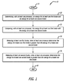
- FIG. 1 is a flow diagram showing the disclosed method 10 for distributing energy amongst at least one first brake and at least one second brake for a vehicle, in accordance with at least one embodiment of the present disclosure.
- at least one processor determines an energy for at least one first brake and an energy for at least one second brake 20. Then, at least one processor compares the energy for at least one first brake with the energy for at least one second brake 25. When at least one processor determines that the energy of at least one first brake is greater than the energy for at least one second brake, at least one first brake is released 30. When at least one processor determines that the energy of at least one second brake is greater than the energy for at least one first brake, at least one second brake is released 35.
- At least one first brake may be at least one aft brake and/or at least one forward brake.
- at least one second brake may be at least one forward brake and/or at least one aft brake.
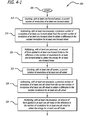
- FIG. 2 is a schematic diagram 100 illustrating the disclosed logic for distributing energy amongst at least one forward brake and at least one aft brake for a vehicle, where the difference in brake energy is greater than zero 105, in accordance with at least one embodiment of the present disclosure.
- data for the forward braking system is being compared to data for the aft braking system.
- data for some of the brakes may be compared to data for the remaining brakes (which may include some of the forward brakes and/or some of the aft brakes).
- At least one forward sensor counts a current number of revolutions of at least one forward wheel (i.e. revolution count forward (rev CNT FWD)) 110.
- At least one processor subtracts 120 a previous number of revolutions of at least one forward wheel (i.e. previous revolution count forward (Prev rev CNT FWD)) 115 from the current number of revolutions of at least one forward wheel (i.e. rev CNT FWD) 110 to obtain a difference in the number of revolutions for at least one forward wheel (i.e. revolution difference forward (rev DIFF FWD)) 125.
- a revolution count of the wheel(s) is performed every clock cycle and, as such, a "previous revolution count” is the revolution count of the wheel(s) from the previous clock cycle.
- the intent is to keep track of how far the vehicle (e.g., airplane) has travelled since the last clock cycle. Since the disclosed system counts wheel revolution, this is the unit of measurement the system uses.
- At least one processor multiplies 130 an amount of force applied to at least one forward brake (i.e. brake command forward (BRK CMD FWD)) 135 to the difference in the number of revolutions for at least one forward wheel (i.e. rev DIFF FWD) 125 to obtain the energy for at least one forward brake (i.e. brake energy forward (BRK energy FWD)) 140.
- brake command forward i.e. brake command forward (BRK CMD FWD)
- rev DIFF FWD i.e. rev DIFF FWD
- BRK energy forward brake energy forward
- the force level may vary over time. The disclosed system will used the most recent force level value for the brake energy calculation.
- At least one aft sensor counts a current number of revolutions of at least one aft wheel (i.e. revolution count aft (rev CNT AFT)) 145.
- At least one processor subtracts 155 a previous number of revolutions of at least one aft wheel (i.e. previous revolution count aft (Prev rev CNT AFT)) 150 from the current number of revolutions of at least one aft wheel (i.e. rev CNT AFT) 145 to obtain a difference in the number of revolutions for at least one aft wheel (i.e. revolution difference aft (rev DIFF AFT)) 160.
- At least one processor multiplies 165 an amount of force applied to at least one aft brake (i.e. brake command aft (BRK CMD AFT)) 170 to the difference in the number of revolutions for at least one aft wheel (i.e. rev DIFF AFT) 160 to obtain the energy for at least one aft brake (i.e. brake energy aft (BRK energy AFT)) 175.
- aft brake i.e. brake command aft (BRK CMD AFT)
- the historical braking data that is retained are the forward and aft revolution counts from the previous clock cycles as well as the forward and aft brake energy calculation from the previous clock cycle.
- At least one processor then subtracts an energy for at least one aft brake (i.e. BRK energy AFT) 175 from an energy for at least one forward brake (i.e. BRK energy FWD) 140 to obtain a difference in brake energy (i.e. brake energy difference (BRK energy DIFF)) 185.
- aft brake i.e. BRK energy AFT
- BRK energy FWD forward brake
- BRK energy difference i.e. brake energy difference (BRK energy DIFF)
- At least one processor multiplies 190 a previous difference in brake energy (i.e. previous brake energy difference (Prev BRK energy DIFF)) 191 with a brake cooling factor (i.e. brake cool factor (BRK Cool Factor)) 192 to obtain a remaining amount of brake energy (i.e. remaining amount brake energy (remaining amount BRK energy)) 193.
- a previous difference in brake energy i.e. previous brake energy difference (Prev BRK energy DIFF)
- a brake cooling factor i.e. brake cool factor (BRK Cool Factor)
- the cooling factor is a value between zero (0), for maximum cooling, and one (1), for no cooling.
- the material of the brakes including, but not limited to, the material of the brakes, the ambient temperature effect, the loading of the vehicle (e..g, the aircraft), the road (e.g., runway) conditions, and the weather conditions.
- At least one processor adds 194 the remaining amount of brake energy (i.e. remaining amount BRK energy) 193 to the difference in brake energy (i.e. BRK energy DIFF) 185 to obtain an updated difference in brake energy (i.e. brake energy difference prime (BRK energy DIFF')) 195. Then, at least one processor determines whether the updated difference in brake energy (i.e. BRK energy DIFF') 195 is greater than zero (0) 196. For this example, at least one processor has determined that the updated difference in brake energy (i.e. BRK energy DIFF') 195 is greater than zero 105. In response, a switch 197 is switched to a position such that at least one forward brake is released during the braking application.
- FIG. 3 is a schematic diagram 200 depicting the disclosed logic for distributing energy amongst at least one forward brake and at least one aft brake for a vehicle, where the difference in brake energy is less than or equal to zero 106, in accordance with at least one embodiment of the present disclosure.
- the logic depicted in FIG. 3 is the same as the logic shown in FIG. 2 .
- FIG. 3 is simply presented to show how the switch 197 changes its position when the updated difference in brake energy (i.e. BRK energy DIFF') 195 is not greater than zero 106.
- at least one processor has determined that the updated difference in brake energy (i.e. BRK energy DIFF') 195 is not greater than zero 106.
- the switch 197 is switched to a position such that at least one aft brake is released during the braking application.
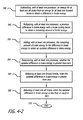
- FIG. 4 is a flow diagram 300 showing the disclosed method for distributing energy amongst at least one forward brake and at least one aft brake for a vehicle, in accordance with at least one embodiment of the present disclosure.
- at least one forward sensor counts a current number of revolutions of at least one forward wheel 310.
- at least one processor subtracts a previous number of revolutions of at least one forward wheel from the current number of revolutions of at least one forward wheel to obtain a difference in the number revolutions for at least one forward wheel 315.
- At least one processor then multiples an amount of force applied to at least one forward brake to the difference in the number of revolutions for at least one forward wheel to obtain the energy for at least one forward brake 320.
- At least one aft sensor counts a current number of revolutions of at least one aft wheel 325. At least one processor then subtracts a previous number of revolutions of at least one aft wheel from the current number of revolutions of at least one aft wheel to obtain a difference in the number revolutions for at least one aft wheel 330. Then, at least one processor multiplies an amount of force applied to at least one aft brake to the difference in the number of revolutions for at least one aft wheel to obtain the energy for at least one aft brake 335.
- At least one processor subtracts an energy for at least one aft brake from an energy for at least one forward brake to obtain a difference in brake energy 340. Then, at least one processor multiples a previous difference in brake energy with a brake cooling factor to obtain a remaining amount of brake energy 345. At least one processor then adds the remaining amount of brake energy to the difference in brake energy 350 to obtain an updated difference in brake energy.
- At least one processor determines whether the updated difference in brake energy is greater than zero 355. When the updated difference in brake energy is greater than zero, at least one forward brake is released 360. Conversely, when the updated difference in brake energy is less than or equal to zero, at least one aft brake is released 365. Then, the method 300 ends 370.
- a method for distributing energy amongst at least one forward brake and at least one aft brake for a vehicle comprising subtracting, with at least one processor, an energy for the at least one aft brake from an energy for the at least one forward brake to obtain a difference in brake energy, determining, with the at least one processor, whether the difference in brake energy is greater than zero, releasing the at least one forward brake, when the difference in brake energy is greater than zero and releasing the at least one aft brake, when the difference in brake energy is one of less than zero and equal to zero.
- the method further comprises counting, with at least one forward sensor, a current number of revolutions of at least one forward wheel; and counting, with at least one aft sensor, a current number of revolutions of at least one aft wheel.
- the method further comprises subtracting, with the at least one processor, a previous number of revolutions of at least one forward wheel from a current number of revolutions of the at least one forward wheel to obtain a difference in the number revolutions for the at least one forward wheel, and multiplying, with the at least one processor, an amount of force applied to the at least one forward brake to the difference in the number of revolutions for the at least one forward wheel to obtain the energy for the at least one forward brake.
- the method further comprises subtracting, with the at least one processor, a previous number of revolutions of at least one aft wheel from a current number of revolutions of the at least one aft wheel to obtain a difference in the number revolutions for the at least one aft wheel, and multiplying, with the at least one processor, an amount of force applied to the at least one aft brake to the difference in the number of revolutions for the at least one aft wheel to obtain the energy for the at least one aft brake.
- the method further comprises, prior to the determining of whether the difference in brake energy is greater than zero, adding, with the at least one processor, a remaining amount of brake energy to the difference in brake energy.
- the method further comprises multiplying, with the at least one processor, a previous difference in brake energy with a brake cooling factor to obtain the remaining amount of brake energy.
- the brake cooling factor is related to at least one of a material of the at least one forward brake, a material of the at least one aft brake, an ambient temperature affect, a loading of the vehicle, road conditions, and weather conditions.
- the vehicle employed by the disclosed system, method, and apparatus for stopping energy based selection logic for taxi brake release may be an airborne vehicle, a terrestrial vehicle, or a marine vehicle.
- the airborne vehicle may be an aircraft.
- the forward and aft brakes are associated with at least one landing gear truck containing at least one wheel.
- the terrestrial vehicle may be a train, a truck, a trailer, an automobile, a motorcycle, or a tank.
- the marine vehicle may be a boat or a ship.
- the forward and aft brakes are associated with at least one propeller of the marine vehicle.
Landscapes
- Engineering & Computer Science (AREA)
- Transportation (AREA)
- Mechanical Engineering (AREA)
- Aviation & Aerospace Engineering (AREA)
- Regulating Braking Force (AREA)
- Hydraulic Control Valves For Brake Systems (AREA)
Abstract
Description
- The present disclosure relates to taxi brake release. In particular, it relates to stopping energy based selection logic for taxi brake release.
- Currently, a conventional brake selection method employs a simply alternating scheme where consecutive brake pedal applications switch back and forth the releasing of the forward and the aft brakes in vehicles, such as in aircraft. This method simply assumes that alternating the forward and the aft brakes with every application will evenly distribute the brake energy (i.e. the stopping energy). This method does not account for variations in brake pedal application by the pilot.
- On a Boeing 777 aircraft, for example, this conventional alternating method performs adequately because the aircraft has a six-wheel truck and, as such, the method releases two wheels per truck, thereby distributing the brake energy over two-thirds (2/3) of the wheels. However, on a Boeing 787 aircraft, for example, this method does not perform adequately because the aircraft has a four-wheel truck and, thus, the method releases two wheels per truck, thereby distributing the brake energy over only one-half (1/2) of the wheels. Therefore, there is a need for a solution that provides selection logic for taxi brake release based on stopping energy.
- The present disclosure relates to a method, system, and apparatus for stopping energy based selection logic for taxi brake release. In one or more embodiments, a method is disclosed for distributing energy amongst at least one first brake and at least one second brake for a vehicle. The disclosed method involves determining, with at least one processor, an energy for at least one first brake and an energy for at least one second brake. Further, the method involves comparing, with at least one processor, the energy for at least one first brake with the energy for at least one second brake. Also, the method involves releasing the at least one first brake, when the at least one processor determines that the energy of the at least one first brake is greater than the energy for the at least one second brake. Further, the method involves releasing the at least one second brake, when the at least one processor determines that the energy of the at least one second brake is greater than the energy for the at least one first brake.
- In at least one embodiment, the at least one first brake is at least one forward brake, and the at least one second brake is at least one aft brake. In some embodiments, the method further comprises counting, with at least one first sensor, a current number of revolutions of at least one first wheel. In one or more embodiments, the method further comprises counting, with at least one second sensor, a current number of revolutions of at least one second wheel.
- In one or more embodiments, the method further involves subtracting, with at least one processor, a previous number of revolutions of at least one first wheel from a current number of revolutions of at least one first wheel to obtain a difference in the number revolutions for at least one first wheel. In addition, the method further involves multiplying, with at least one processor, an amount of force applied to at least one first brake to the difference in the number of revolutions for at least one first wheel to obtain the energy for at least one first brake.
- In at least one embodiment, the method further involves subtracting, with at least one processor, a previous number of revolutions of at least one second wheel from a current number of revolutions of at least one second wheel to obtain a difference in the number revolutions for at least one second wheel. Also, the method further involves multiplying, with at least one processor, an amount of force applied to at least one second brake to the difference in the number of revolutions for at least one second wheel to obtain the energy for at least one second brake.
- In at least one embodiment, a method for distributing energy amongst at least one forward brake and at least one aft brake for a vehicle involves subtracting, with at least one processor, an energy for at least one aft brake from an energy for at least one forward brake to obtain a difference in brake energy. Also, the method involves determining, with at least one processor, whether the difference in brake energy is greater than zero. In addition, the method involves releasing at least one forward brake, when the difference in brake energy is greater than zero. Further, the method involves releasing at least one aft brake, when the difference in brake energy is less than or equal to zero.
- In one or more embodiments, the disclosed method further involves counting, with at least one forward sensor, a current number of revolutions of at least one forward wheel. In some embodiments, the method further involves counting, with at least one aft sensor, a current number of revolutions of at least one aft wheel.
- In at least one embodiment, the method further involves subtracting, with at least one processor, a previous number of revolutions of at least one forward wheel from a current number of revolutions of at least one forward wheel to obtain a difference in the number revolutions for at least one forward wheel. Also, the method involves multiplying, with at least one processor, an amount of force applied to at least one forward brake to the difference in the number of revolutions for at least one forward wheel to obtain the energy for at least one forward brake.
- In one or more embodiments, the method further involves subtracting, with at least one processor, a previous number of revolutions of at least one aft wheel from a current number of revolutions of at least one aft wheel to obtain a difference in the number revolutions for at least one aft wheel. In addition, the method involves multiplying, with at least one processor, an amount of force applied to at least one aft brake to the difference in the number of revolutions for at least one aft wheel to obtain the energy for at least one aft brake.
- In at least one embodiment, the method further involves, prior to the determining of whether the difference in brake energy is greater than zero, adding, with at least one processor, a remaining amount of brake energy to the difference in brake energy. In some embodiments, the method further involves multiplying, with at least one processor, a previous difference in brake energy with a brake cooling factor to obtain the remaining amount of brake energy. In one or more embodiments, the brake cooling factor is related to a material of at least one forward brake, a material of at least one aft brake, an ambient temperature effect, a loading of the vehicle (e.g., an aircraft), road (e.g., runway) conditions, and/or weather conditions.
- In one or more embodiments, a system is disclosed for distributing energy amongst at least one forward brake and at least one aft brake for a vehicle. The disclosed system includes at least one forward brake and at least one aft brake. Also, the system includes at least one processor configured to subtract an energy for the at least one aft brake from an energy for the at least one forward brake to obtain a difference in brake energy, and to determine whether the difference in brake energy is greater than zero. In one or more embodiments, when the difference in brake energy is greater than zero, the at least one forward brake is released. In at least one embodiment, when the difference in brake energy is less than or equal to zero, the at least one aft brake is released.
- In at least one embodiment, the vehicle is an airborne vehicle, a terrestrial vehicle, or a marine vehicle. In some embodiments, the airborne vehicle is an aircraft. For these embodiments, the forward and aft brakes are associated with at least one landing gear truck containing at least one wheel. In one or more embodiments, the terrestrial vehicle is a train, a truck, a trailer, an automobile, a motorcycle, or a tank. In some embodiments, the marine vehicle is a boat or a ship. For these embodiments, the forward and aft brakes are associated with at least one propeller of the marine vehicle.
- In one or more embodiments, the system further includes at least one forward wheel, and at least one forward sensor to count a current number of revolutions of at least one forward wheel. In some embodiments, the system further includes at least one aft wheel, and at least one aft sensor to count a current number of revolutions of at least one aft wheel.
- In at least one embodiment, the at least one processor is further configured to subtract a previous number of revolutions of at least one forward wheel from a current number of revolutions of at least one forward wheel to obtain a difference in the number revolutions for at least one forward wheel, and to multiply an amount of force applied to at least one forward brake to the difference in the number of revolutions for at least one forward wheel to obtain the energy for at least one forward brake.
- In one or more embodiments, the at least one processor is further configured to subtract a previous number of revolutions of at least one aft wheel from a current number of revolutions of at least one aft wheel to obtain a difference in the number revolutions for at least one aft wheel, and to multiply an amount of force applied to at least one aft brake to the difference in the number of revolutions for at least one aft wheel to obtain the energy for at least one aft brake.
- In at least one embodiment, the at least one processor is further configured to add a remaining amount of brake energy to the difference in brake energy. In some embodiments, the at least one processor is further configured to multiply a previous difference in brake energy with a brake cooling factor to obtain the remaining amount of brake energy. In one or more embodiments, the brake cooling factor is a value equal to or greater than zero (0) and less than or equal to one (1).
- The features, functions, and advantages can be achieved independently in various embodiments of the present inventions or may be combined in yet other embodiments.
- These and other features, aspects, and advantages of the present disclosure will become better understood with regard to the following description, appended claims, and accompanying drawings where:
-
FIG. 1 is a flow diagram showing the disclosed method for distributing energy amongst at least one first brake and at least one second brake for a vehicle, in accordance with at least one embodiment of the present disclosure. -
FIG. 2 is a schematic diagram illustrating the disclosed logic for distributing energy amongst at least one forward brake and at least one aft brake for a vehicle, where the difference in brake energy is greater than zero, in accordance with at least one embodiment of the present disclosure. -
FIG. 3 is a schematic diagram depicting the disclosed logic for distributing energy amongst at least one forward brake and at least one aft brake for a vehicle, where the difference in brake energy is less than or equal to zero, in accordance with at least one embodiment of the present disclosure. -
FIG. 4 is a flow diagram showing the disclosed method for distributing energy amongst at least one forward brake and at least one aft brake for a vehicle, in accordance with at least one embodiment of the present disclosure. - The methods and apparatus disclosed herein provide an operative system for stopping energy based selection logic for taxi brake release. In particular, the disclosed logic is to be used for the taxi brake release function to determine which brake (i.e. the forward brake or the aft brake) to select based on the amount of brake energy absorbed. This logic uses wheel revolution counts and brake commands during a braking cycle to determine which brake has absorbed more energy. The brake that has absorbed more energy would be the hottest brake and, as such, that brake is released while taxiing.
- During operation of the system, the system will determine the distance traveled by counting the wheel rotations. The distance will be multiplied by the brake force command (i.e. the amount of force applied to the brake) to determine the energy being absorbed by the brakes. The difference in brake energy for the current cycle will be determined by subtracting the aft brake energy value from the forward brake energy value. The overall value will be calculated by then taking the brake energy difference calculation from the previous cycle, multiplying it to a cooling factor (e.g., a value between zero (0), for maximum (instant) cooling, and one (1), for no cooling), and adding it to the current energy difference. If the value is a positive value, the forward brake has more energy and, thus, will be released during taxi braking. Conversely, if the value is a negative value, the aft brake has more energy and, as such, will be released during taxi braking. This releasing of the brake with more absorbed energy will reduce the likelihood that there will be a large difference in brake temperatures leading to brake overheating. An advantage of this system is that it accounts for variations introduced by a pilot who applies uneven brake commands during pedal application.
- In the following description, numerous details are set forth in order to provide a more thorough description of the system. It will be apparent, however, to one skilled in the art, that the disclosed system may be practiced without these specific details. In the other instances, well known features have not been described in detail so as not to unnecessarily obscure the system.
-
FIG. 1 is a flow diagram showing the disclosedmethod 10 for distributing energy amongst at least one first brake and at least one second brake for a vehicle, in accordance with at least one embodiment of the present disclosure. At thestart 15 of themethod 10, at least one processor determines an energy for at least one first brake and an energy for at least onesecond brake 20. Then, at least one processor compares the energy for at least one first brake with the energy for at least onesecond brake 25. When at least one processor determines that the energy of at least one first brake is greater than the energy for at least one second brake, at least one first brake is released 30. When at least one processor determines that the energy of at least one second brake is greater than the energy for at least one first brake, at least one second brake is released 35. Then, themethod 10 ends 40. It should be noted that in various embodiments, at least one first brake may be at least one aft brake and/or at least one forward brake. In addition, at least one second brake may be at least one forward brake and/or at least one aft brake. -
FIG. 2 is a schematic diagram 100 illustrating the disclosed logic for distributing energy amongst at least one forward brake and at least one aft brake for a vehicle, where the difference in brake energy is greater than zero 105, in accordance with at least one embodiment of the present disclosure. For this figure, data for the forward braking system is being compared to data for the aft braking system. However, it should be noted that in alternative embodiments, data for some of the brakes (which may include some of the forward brakes and/or some of the aft brakes) may be compared to data for the remaining brakes (which may include some of the forward brakes and/or some of the aft brakes). - For this logic, at least one forward sensor counts a current number of revolutions of at least one forward wheel (i.e. revolution count forward (rev CNT FWD)) 110. At least one processor subtracts 120 a previous number of revolutions of at least one forward wheel (i.e. previous revolution count forward (Prev rev CNT FWD)) 115 from the current number of revolutions of at least one forward wheel (i.e. rev CNT FWD) 110 to obtain a difference in the number of revolutions for at least one forward wheel (i.e. revolution difference forward (rev DIFF FWD)) 125. It should be noted that a revolution count of the wheel(s) is performed every clock cycle and, as such, a "previous revolution count" is the revolution count of the wheel(s) from the previous clock cycle. The intent is to keep track of how far the vehicle (e.g., airplane) has travelled since the last clock cycle. Since the disclosed system counts wheel revolution, this is the unit of measurement the system uses.
- Then, at least one processor multiplies 130 an amount of force applied to at least one forward brake (i.e. brake command forward (BRK CMD FWD)) 135 to the difference in the number of revolutions for at least one forward wheel (i.e. rev DIFF FWD) 125 to obtain the energy for at least one forward brake (i.e. brake energy forward (BRK energy FWD)) 140. It should be noted that the force level may vary over time. The disclosed system will used the most recent force level value for the brake energy calculation.
- Similarly, at least one aft sensor counts a current number of revolutions of at least one aft wheel (i.e. revolution count aft (rev CNT AFT)) 145. At least one processor subtracts 155 a previous number of revolutions of at least one aft wheel (i.e. previous revolution count aft (Prev rev CNT AFT)) 150 from the current number of revolutions of at least one aft wheel (i.e. rev CNT AFT) 145 to obtain a difference in the number of revolutions for at least one aft wheel (i.e. revolution difference aft (rev DIFF AFT)) 160. Then, at least one processor multiplies 165 an amount of force applied to at least one aft brake (i.e. brake command aft (BRK CMD AFT)) 170 to the difference in the number of revolutions for at least one aft wheel (i.e. rev DIFF AFT) 160 to obtain the energy for at least one aft brake (i.e. brake energy aft (BRK energy AFT)) 175.
- It should be noted that for the disclosed system, the historical braking data that is retained are the forward and aft revolution counts from the previous clock cycles as well as the forward and aft brake energy calculation from the previous clock cycle.
- At least one processor then subtracts an energy for at least one aft brake (i.e. BRK energy AFT) 175 from an energy for at least one forward brake (i.e. BRK energy FWD) 140 to obtain a difference in brake energy (i.e. brake energy difference (BRK energy DIFF)) 185.
- Also, at least one processor multiplies 190 a previous difference in brake energy (i.e. previous brake energy difference (Prev BRK energy DIFF)) 191 with a brake cooling factor (i.e. brake cool factor (BRK Cool Factor)) 192 to obtain a remaining amount of brake energy (i.e. remaining amount brake energy (remaining amount BRK energy)) 193. For example, the cooling factor is a value between zero (0), for maximum cooling, and one (1), for no cooling. Various different types of factors and/or characteristic may be used to determine the value to use for the cooling factor including, but not limited to, the material of the brakes, the ambient temperature effect, the loading of the vehicle (e..g, the aircraft), the road (e.g., runway) conditions, and the weather conditions.
- Then, at least one processor adds 194 the remaining amount of brake energy (i.e. remaining amount BRK energy) 193 to the difference in brake energy (i.e. BRK energy DIFF) 185 to obtain an updated difference in brake energy (i.e. brake energy difference prime (BRK energy DIFF')) 195. Then, at least one processor determines whether the updated difference in brake energy (i.e. BRK energy DIFF') 195 is greater than zero (0) 196. For this example, at least one processor has determined that the updated difference in brake energy (i.e. BRK energy DIFF') 195 is greater than zero 105. In response, a
switch 197 is switched to a position such that at least one forward brake is released during the braking application. -
FIG. 3 is a schematic diagram 200 depicting the disclosed logic for distributing energy amongst at least one forward brake and at least one aft brake for a vehicle, where the difference in brake energy is less than or equal to zero 106, in accordance with at least one embodiment of the present disclosure. It should be noted that the logic depicted inFIG. 3 is the same as the logic shown inFIG. 2 .FIG. 3 is simply presented to show how theswitch 197 changes its position when the updated difference in brake energy (i.e. BRK energy DIFF') 195 is not greater than zero 106. As such, for this example, at least one processor has determined that the updated difference in brake energy (i.e. BRK energy DIFF') 195 is not greater than zero 106. In response, theswitch 197 is switched to a position such that at least one aft brake is released during the braking application. -
FIG. 4 is a flow diagram 300 showing the disclosed method for distributing energy amongst at least one forward brake and at least one aft brake for a vehicle, in accordance with at least one embodiment of the present disclosure. At thestart 305 of themethod 300, at least one forward sensor counts a current number of revolutions of at least oneforward wheel 310. Then, at least one processor subtracts a previous number of revolutions of at least one forward wheel from the current number of revolutions of at least one forward wheel to obtain a difference in the number revolutions for at least oneforward wheel 315. At least one processor then multiples an amount of force applied to at least one forward brake to the difference in the number of revolutions for at least one forward wheel to obtain the energy for at least oneforward brake 320. - In addition, at least one aft sensor counts a current number of revolutions of at least one
aft wheel 325. At least one processor then subtracts a previous number of revolutions of at least one aft wheel from the current number of revolutions of at least one aft wheel to obtain a difference in the number revolutions for at least oneaft wheel 330. Then, at least one processor multiplies an amount of force applied to at least one aft brake to the difference in the number of revolutions for at least one aft wheel to obtain the energy for at least oneaft brake 335. - Additionally, at least one processor subtracts an energy for at least one aft brake from an energy for at least one forward brake to obtain a difference in
brake energy 340. Then, at least one processor multiples a previous difference in brake energy with a brake cooling factor to obtain a remaining amount ofbrake energy 345. At least one processor then adds the remaining amount of brake energy to the difference inbrake energy 350 to obtain an updated difference in brake energy. - In addition, at least one processor determines whether the updated difference in brake energy is greater than zero 355. When the updated difference in brake energy is greater than zero, at least one forward brake is released 360. Conversely, when the updated difference in brake energy is less than or equal to zero, at least one aft brake is released 365. Then, the
method 300 ends 370. - According to an aspect of the present disclosure there is provided a method for distributing energy amongst at least one forward brake and at least one aft brake for a vehicle, the method comprising subtracting, with at least one processor, an energy for the at least one aft brake from an energy for the at least one forward brake to obtain a difference in brake energy, determining, with the at least one processor, whether the difference in brake energy is greater than zero, releasing the at least one forward brake, when the difference in brake energy is greater than zero and releasing the at least one aft brake, when the difference in brake energy is one of less than zero and equal to zero.
- According to a further aspect of the present disclosure there is provided the method, wherein the method further comprises counting, with at least one forward sensor, a current number of revolutions of at least one forward wheel; and counting, with at least one aft sensor, a current number of revolutions of at least one aft wheel.
- According to a further aspect of the present disclosure there is provided the method, wherein the method further comprises subtracting, with the at least one processor, a previous number of revolutions of at least one forward wheel from a current number of revolutions of the at least one forward wheel to obtain a difference in the number revolutions for the at least one forward wheel, and multiplying, with the at least one processor, an amount of force applied to the at least one forward brake to the difference in the number of revolutions for the at least one forward wheel to obtain the energy for the at least one forward brake.
- According to a further aspect of the present disclosure there is provided he method of, wherein the method further comprises subtracting, with the at least one processor, a previous number of revolutions of at least one aft wheel from a current number of revolutions of the at least one aft wheel to obtain a difference in the number revolutions for the at least one aft wheel, and multiplying, with the at least one processor, an amount of force applied to the at least one aft brake to the difference in the number of revolutions for the at least one aft wheel to obtain the energy for the at least one aft brake.
- According to a further aspect of the present disclosure there is provided the method, wherein the method further comprises, prior to the determining of whether the difference in brake energy is greater than zero, adding, with the at least one processor, a remaining amount of brake energy to the difference in brake energy.
- According to a further aspect of the present disclosure there is provided the method, wherein the method further comprises multiplying, with the at least one processor, a previous difference in brake energy with a brake cooling factor to obtain the remaining amount of brake energy.
- According to a further aspect of the present disclosure there is provided the method, wherein the brake cooling factor is related to at least one of a material of the at least one forward brake, a material of the at least one aft brake, an ambient temperature affect, a loading of the vehicle, road conditions, and weather conditions.
- It should be noted that the vehicle employed by the disclosed system, method, and apparatus for stopping energy based selection logic for taxi brake release may be an airborne vehicle, a terrestrial vehicle, or a marine vehicle. In some embodiments, the airborne vehicle may be an aircraft. For these embodiments, the forward and aft brakes are associated with at least one landing gear truck containing at least one wheel. In one or more embodiments, the terrestrial vehicle may be a train, a truck, a trailer, an automobile, a motorcycle, or a tank. In some embodiments, the marine vehicle may be a boat or a ship. For these embodiments, the forward and aft brakes are associated with at least one propeller of the marine vehicle.
- Although certain illustrative embodiments and methods have been disclosed herein, it can be apparent from the foregoing disclosure to those skilled in the art that variations and modifications of such embodiments and methods can be made without departing from the true spirit and scope of the art disclosed. Many other examples of the art disclosed exist, each differing from others in matters of detail only. Accordingly, it is intended that the art disclosed shall be limited only to the extent required by the appended claims and the rules and principles of applicable law.
Claims (15)
- A method for distributing energy amongst at least one first brake and at least one second brake for a vehicle, the method comprising:determining, with at least one processor, an energy for the at least one first brake and an energy for the at least one second brake (20);comparing, with the at least one processor, the energy for the at least one first brake with the energy for the at least one second brake (25);releasing the at least one first brake, when the at least one processor determines the energy of the at least one first brake is greater than the energy for the at least one second brake (30); andreleasing the at least one second brake, when the at least one processor determines the energy of the at least one second brake is greater than the energy for the at least one first brake (35).
- The method of claim 1, wherein the at least one first brake is at least one forward brake, and wherein the at least one second brake is at least one aft brake.
- The method of claims 1 and 2, wherein the method further comprises counting, with at least one first sensor, a current number of revolutions of at least one first wheel (300).
- The method of claim 3, wherein the method further comprises counting, with at least one second sensor, a current number of revolutions of at least one second wheel (325).
- The method of any of claims 1-4, wherein the method further comprises:subtracting, with the at least one processor, a previous number of revolutions of at least one first wheel from a current number of revolutions of the at least one first wheel to obtain a difference in the number revolutions for the at least one first wheel (315), andmultiplying, with the at least one processor, an amount of force applied to the at least one first brake to the difference in the number of revolutions for the at least one first wheel to obtain the energy for the at least one first brake (320).
- The method of any of claims 1-5, wherein the method further comprises subtracting, with the at least one processor, a previous number of revolutions of at least one second wheel from a current number of revolutions of the at least one second wheel to obtain a difference in the number revolutions for the at least one second wheel (330); and
multiplying, with the at least one processor, an amount of force applied to the at least one second brake to the difference in the number of revolutions for the at least one second wheel to obtain the energy for the at least one second brake (335). - The method of any of claims 1-6, wherein comparing the energy for the at least one first brake with the energy for the at least one second brake comprises:Subtracting, with the at least one processor, the energy for the at least one second brake from the energy for the at least one first brake to obtain a difference in brake energy,adding, with the at least one processor, a remaining amount of brake energy to the difference in brake energy, anddetermining whether the sum of the difference in brake energy and the remaining amount of brake energy is greater than zero.
- The method of claim 7, further comprising multiplying, with the at least one processor, a previous difference in brake energy with a brake cooling factor to obtain the remaining amount of brake energy.
- A system for distributing energy amongst at least one forward brake and at least one aft brake for a vehicle, the system comprising:the at least one forward brake;the at least one aft brake; andat least one processor configured to subtract an energy for the at least one aft brake from an energy for the at least one forward brake to obtain a difference in brake energy, and to determine whether the difference in brake energy is greater than zero,wherein the system is configured to release at least one forward brake when the difference in brake energy is greater than zero, andwherein the system is configured to release the at least one aft brake when the difference in brake energy is one of less than zero and equal to zero.
- The system of claim 9, wherein the vehicle is one of an airborne vehicle, a terrestrial vehicle, and a marine vehicle.
- The system of claim 9 or 10, wherein the system further comprises:at least one forward wheel;at least one forward sensor to count a current number of revolutions of the at least one forward wheel;at least one aft wheel; andat least one aft sensor to count a current number of revolutions of the at least one aft wheel.
- The system of any of claims 9-11, wherein the at least one processor is further configured to subtract a previous number of revolutions of at least one forward wheel from a current number of revolutions of the at least one forward wheel to obtain a difference in the number revolutions for the at least one forward wheel, and to multiply an amount of force applied to the at least one forward brake to the difference in the number of revolutions for the at least one forward wheel to obtain the energy for the at least one forward brake.
- The system of any of claims 9-12, wherein the at least one processor is further configured to subtract a previous number of revolutions of at least one aft wheel from a current number of revolutions of the at least one aft wheel to obtain a difference in the number revolutions for the at least one aft wheel, and to multiply an amount of force applied to the at least one aft brake to the difference in the number of revolutions for the at least one aft wheel to obtain the energy for the at least one aft brake.
- The system of any of claims 9-13, wherein the at least one processor is further configured to add a remaining amount of brake energy to the difference in brake energy prior to the determining whether the difference in brake energy is greater than zero.
- The system of claim 14, wherein the at least one processor is further configured to multiply a previous difference in braking energy with a brake cooling factor to obtain the remaining amount of brake energy.
Applications Claiming Priority (1)
| Application Number | Priority Date | Filing Date | Title |
|---|---|---|---|
| US13/972,645 US9914442B2 (en) | 2013-08-21 | 2013-08-21 | Stopping energy based selection logic for taxi brake release |
Publications (3)
| Publication Number | Publication Date |
|---|---|
| EP2848479A2 true EP2848479A2 (en) | 2015-03-18 |
| EP2848479A3 EP2848479A3 (en) | 2016-03-09 |
| EP2848479B1 EP2848479B1 (en) | 2017-06-14 |
Family
ID=51298628
Family Applications (1)
| Application Number | Title | Priority Date | Filing Date |
|---|---|---|---|
| EP14180411.2A Active EP2848479B1 (en) | 2013-08-21 | 2014-08-08 | Stopping energy based selection logic for taxi brake release |
Country Status (6)
| Country | Link |
|---|---|
| US (1) | US9914442B2 (en) |
| EP (1) | EP2848479B1 (en) |
| JP (1) | JP6663638B2 (en) |
| CN (1) | CN104417515B (en) |
| BR (1) | BR102014020066B1 (en) |
| ES (1) | ES2640026T3 (en) |
Cited By (1)
| Publication number | Priority date | Publication date | Assignee | Title |
|---|---|---|---|---|
| WO2019023029A1 (en) * | 2017-07-24 | 2019-01-31 | Bendix Commercial Vehicle Systems Llc | Brake adjustment detection using wheel speed sensor based thermal measurement |
Families Citing this family (4)
| Publication number | Priority date | Publication date | Assignee | Title |
|---|---|---|---|---|
| GB2576937A (en) | 2018-09-07 | 2020-03-11 | Airbus Operations Ltd | Controlling aircraft wheel brakes |
| GB2584426B (en) * | 2019-05-28 | 2024-03-27 | Haldex Brake Prod Ab | Vehicle braking system |
| US11364884B2 (en) | 2019-07-02 | 2022-06-21 | Goodrich Corporation | Selective braking of carbon brakes to improve life |
| US12162456B2 (en) * | 2021-11-19 | 2024-12-10 | Goodrich Corporation | Feel adjustment braking systems and methods |
Family Cites Families (18)
| Publication number | Priority date | Publication date | Assignee | Title |
|---|---|---|---|---|
| US4078845A (en) * | 1976-08-13 | 1978-03-14 | The Boeing Company | Limited-slip brake control system |
| US4180223A (en) * | 1977-12-28 | 1979-12-25 | The Boeing Company | Limited-slip brake control system |
| US4195472A (en) * | 1978-02-08 | 1980-04-01 | General Motors Corporation | Gas turbine with forward and reverse marine drive |
| JPS62279165A (en) * | 1986-05-23 | 1987-12-04 | ランドエア ダイナブレイク インコ−ポレ−テツド | Brake gear |
| CA1323061C (en) * | 1988-02-16 | 1993-10-12 | Ian Leonard Stimson | Aircraft braking systems |
| US4923056A (en) | 1989-02-21 | 1990-05-08 | Aircraft Braking Systems Corporation | Method of increasing the service life of aircraft carbon disk brakes |
| US6604708B1 (en) * | 1989-12-26 | 2003-08-12 | The Boeing Company | Carbon brake wear for aircraft |
| US5136508A (en) * | 1990-06-19 | 1992-08-04 | Allied-Signal Inc. | Brake lining temperature prediction for a traction control system |
| FR2672350A1 (en) * | 1991-02-06 | 1992-08-07 | Messier Bugatti | CONTROLLED BRAKING DEVICE OF A WHEEL TRAIN IN PARTICULAR AN AIRCRAFT WHEEL TRAIN. |
| US5431241A (en) * | 1994-05-31 | 1995-07-11 | Zexel-Gleason Usa, Inc. | Hybrid traction control system |
| GB9418476D0 (en) | 1994-09-14 | 1994-11-02 | Dunlop Ltd | Sequential selective operation of aircraft brakes |
| JP3846273B2 (en) * | 2001-11-07 | 2006-11-15 | トヨタ自動車株式会社 | Brake device |
| AU2002352050A1 (en) * | 2001-11-23 | 2003-06-10 | Lucas Automotive Gmbh | Operation of a vehicle brake system depending on brake surface temperatures |
| US7244003B2 (en) * | 2004-12-20 | 2007-07-17 | International Truck Intellectual Property Company, Llc | Vehicle onboard brake pad/lining wear estimators with temperature estimations |
| US7410224B2 (en) | 2006-01-19 | 2008-08-12 | Hydro-Aire, Inc. | Method and system to increase electric brake clamping force accuracy |
| US8386094B2 (en) * | 2009-01-29 | 2013-02-26 | Hydro-Aire, Inc. | Taxi brake inhibit system |
| US8403429B2 (en) * | 2011-04-15 | 2013-03-26 | Meggitt Aircraft Braking Systems | Balanced brake control system |
| JP5234142B2 (en) | 2011-06-23 | 2013-07-10 | 日産自動車株式会社 | Lane departure prevention device |
-
2013
- 2013-08-21 US US13/972,645 patent/US9914442B2/en active Active
-
2014
- 2014-08-08 ES ES14180411.2T patent/ES2640026T3/en active Active
- 2014-08-08 EP EP14180411.2A patent/EP2848479B1/en active Active
- 2014-08-13 BR BR102014020066-5A patent/BR102014020066B1/en active IP Right Grant
- 2014-08-18 JP JP2014165670A patent/JP6663638B2/en active Active
- 2014-08-21 CN CN201410415517.7A patent/CN104417515B/en active Active
Non-Patent Citations (1)
| Title |
|---|
| None |
Cited By (2)
| Publication number | Priority date | Publication date | Assignee | Title |
|---|---|---|---|---|
| WO2019023029A1 (en) * | 2017-07-24 | 2019-01-31 | Bendix Commercial Vehicle Systems Llc | Brake adjustment detection using wheel speed sensor based thermal measurement |
| US10457263B2 (en) | 2017-07-24 | 2019-10-29 | Bendix Commercial Vehicle Systems, Llc | Brake adjustment detection using WSS based thermal measurement |
Also Published As
| Publication number | Publication date |
|---|---|
| US20150057902A1 (en) | 2015-02-26 |
| JP2015040041A (en) | 2015-03-02 |
| CN104417515A (en) | 2015-03-18 |
| BR102014020066B1 (en) | 2022-03-15 |
| ES2640026T3 (en) | 2017-10-31 |
| JP6663638B2 (en) | 2020-03-13 |
| CN104417515B (en) | 2018-06-05 |
| BR102014020066A2 (en) | 2015-09-22 |
| US9914442B2 (en) | 2018-03-13 |
| EP2848479B1 (en) | 2017-06-14 |
| EP2848479A3 (en) | 2016-03-09 |
Similar Documents
| Publication | Publication Date | Title |
|---|---|---|
| EP2848479B1 (en) | Stopping energy based selection logic for taxi brake release | |
| US10352774B2 (en) | Methods and apparatus to monitor components of an aircraft landing system | |
| CN103921795B (en) | Vehicle and sliding energy recovery method and system thereof | |
| US9956957B2 (en) | Method and device for regulating a longitudinal acceleration of a vehicle | |
| US9242739B2 (en) | Methods to monitor components of an aircraft landing system | |
| CN104229149B (en) | The aircraft driving assistance method and system of landing period | |
| US9096204B2 (en) | System and method for determining an adaptive turnaround threshold | |
| GB2554097A (en) | Brake wear reduction apparatus | |
| US20230226927A1 (en) | Dynamic torque allocation and efficiency control for electric vehicle | |
| US11524683B2 (en) | Vehicles, methods, and devices for vehicle retarder control and display | |
| US12337724B2 (en) | Vehicle retardation torque control | |
| US20230226926A1 (en) | Dynamic torque allocation and stability control for electric vehicle | |
| CN104590238A (en) | Determining effective brake pedal position | |
| US20240198808A1 (en) | Computer-implemented method of brake management | |
| US20230226925A1 (en) | Loading estimation for electric vehicle | |
| CN109715464A (en) | Method, computer-readable medium, system for assisting the high energy efficiency of vehicle to slow down and with the vehicle of the system | |
| US20160221449A1 (en) | Control of regenerative braking in an electric or hybrid vehicle | |
| CN104842983A (en) | High speed rail braking method and system based on multiple intelligent bodies | |
| US20240416917A1 (en) | Predictive overtaking support | |
| CN118953038B (en) | Vehicle brake control method and device, vehicle and computer storage medium | |
| CN119459348B (en) | Vehicle braking control methods, devices, new energy vehicles and storage media | |
| CN118790255B (en) | Method for starting separated road surface and vehicle | |
| CN118457275A (en) | Control method and device of disengagement mechanism, electronic equipment and vehicle | |
| CN110893775A (en) | Electric vehicle target speed customization system |
Legal Events
| Date | Code | Title | Description |
|---|---|---|---|
| PUAI | Public reference made under article 153(3) epc to a published international application that has entered the european phase |
Free format text: ORIGINAL CODE: 0009012 |
|
| 17P | Request for examination filed |
Effective date: 20140808 |
|
| AK | Designated contracting states |
Kind code of ref document: A2 Designated state(s): AL AT BE BG CH CY CZ DE DK EE ES FI FR GB GR HR HU IE IS IT LI LT LU LV MC MK MT NL NO PL PT RO RS SE SI SK SM TR |
|
| AX | Request for extension of the european patent |
Extension state: BA ME |
|
| PUAL | Search report despatched |
Free format text: ORIGINAL CODE: 0009013 |
|
| AK | Designated contracting states |
Kind code of ref document: A3 Designated state(s): AL AT BE BG CH CY CZ DE DK EE ES FI FR GB GR HR HU IE IS IT LI LT LU LV MC MK MT NL NO PL PT RO RS SE SI SK SM TR |
|
| AX | Request for extension of the european patent |
Extension state: BA ME |
|
| RIC1 | Information provided on ipc code assigned before grant |
Ipc: B60T 8/17 20060101ALI20160203BHEP Ipc: B60T 13/66 20060101AFI20160203BHEP |
|
| GRAP | Despatch of communication of intention to grant a patent |
Free format text: ORIGINAL CODE: EPIDOSNIGR1 |
|
| INTG | Intention to grant announced |
Effective date: 20170105 |
|
| GRAS | Grant fee paid |
Free format text: ORIGINAL CODE: EPIDOSNIGR3 |
|
| GRAA | (expected) grant |
Free format text: ORIGINAL CODE: 0009210 |
|
| AK | Designated contracting states |
Kind code of ref document: B1 Designated state(s): AL AT BE BG CH CY CZ DE DK EE ES FI FR GB GR HR HU IE IS IT LI LT LU LV MC MK MT NL NO PL PT RO RS SE SI SK SM TR |
|
| REG | Reference to a national code |
Ref country code: GB Ref legal event code: FG4D |
|
| REG | Reference to a national code |
Ref country code: CH Ref legal event code: EP Ref country code: AT Ref legal event code: REF Ref document number: 900651 Country of ref document: AT Kind code of ref document: T Effective date: 20170615 |
|
| REG | Reference to a national code |
Ref country code: IE Ref legal event code: FG4D |
|
| REG | Reference to a national code |
Ref country code: DE Ref legal event code: R096 Ref document number: 602014010681 Country of ref document: DE |
|
| REG | Reference to a national code |
Ref country code: FR Ref legal event code: PLFP Year of fee payment: 4 |
|
| REG | Reference to a national code |
Ref country code: NL Ref legal event code: MP Effective date: 20170614 |
|
| REG | Reference to a national code |
Ref country code: LT Ref legal event code: MG4D |
|
| PG25 | Lapsed in a contracting state [announced via postgrant information from national office to epo] |
Ref country code: GR Free format text: LAPSE BECAUSE OF FAILURE TO SUBMIT A TRANSLATION OF THE DESCRIPTION OR TO PAY THE FEE WITHIN THE PRESCRIBED TIME-LIMIT Effective date: 20170915 Ref country code: LT Free format text: LAPSE BECAUSE OF FAILURE TO SUBMIT A TRANSLATION OF THE DESCRIPTION OR TO PAY THE FEE WITHIN THE PRESCRIBED TIME-LIMIT Effective date: 20170614 Ref country code: NO Free format text: LAPSE BECAUSE OF FAILURE TO SUBMIT A TRANSLATION OF THE DESCRIPTION OR TO PAY THE FEE WITHIN THE PRESCRIBED TIME-LIMIT Effective date: 20170914 Ref country code: FI Free format text: LAPSE BECAUSE OF FAILURE TO SUBMIT A TRANSLATION OF THE DESCRIPTION OR TO PAY THE FEE WITHIN THE PRESCRIBED TIME-LIMIT Effective date: 20170614 Ref country code: HR Free format text: LAPSE BECAUSE OF FAILURE TO SUBMIT A TRANSLATION OF THE DESCRIPTION OR TO PAY THE FEE WITHIN THE PRESCRIBED TIME-LIMIT Effective date: 20170614 |
|
| REG | Reference to a national code |
Ref country code: ES Ref legal event code: FG2A Ref document number: 2640026 Country of ref document: ES Kind code of ref document: T3 Effective date: 20171031 |
|
| REG | Reference to a national code |
Ref country code: AT Ref legal event code: MK05 Ref document number: 900651 Country of ref document: AT Kind code of ref document: T Effective date: 20170614 |
|
| PG25 | Lapsed in a contracting state [announced via postgrant information from national office to epo] |
Ref country code: NL Free format text: LAPSE BECAUSE OF FAILURE TO SUBMIT A TRANSLATION OF THE DESCRIPTION OR TO PAY THE FEE WITHIN THE PRESCRIBED TIME-LIMIT Effective date: 20170614 Ref country code: LV Free format text: LAPSE BECAUSE OF FAILURE TO SUBMIT A TRANSLATION OF THE DESCRIPTION OR TO PAY THE FEE WITHIN THE PRESCRIBED TIME-LIMIT Effective date: 20170614 Ref country code: RS Free format text: LAPSE BECAUSE OF FAILURE TO SUBMIT A TRANSLATION OF THE DESCRIPTION OR TO PAY THE FEE WITHIN THE PRESCRIBED TIME-LIMIT Effective date: 20170614 Ref country code: BG Free format text: LAPSE BECAUSE OF FAILURE TO SUBMIT A TRANSLATION OF THE DESCRIPTION OR TO PAY THE FEE WITHIN THE PRESCRIBED TIME-LIMIT Effective date: 20170914 Ref country code: SE Free format text: LAPSE BECAUSE OF FAILURE TO SUBMIT A TRANSLATION OF THE DESCRIPTION OR TO PAY THE FEE WITHIN THE PRESCRIBED TIME-LIMIT Effective date: 20170614 |
|
| PG25 | Lapsed in a contracting state [announced via postgrant information from national office to epo] |
Ref country code: SK Free format text: LAPSE BECAUSE OF FAILURE TO SUBMIT A TRANSLATION OF THE DESCRIPTION OR TO PAY THE FEE WITHIN THE PRESCRIBED TIME-LIMIT Effective date: 20170614 Ref country code: AT Free format text: LAPSE BECAUSE OF FAILURE TO SUBMIT A TRANSLATION OF THE DESCRIPTION OR TO PAY THE FEE WITHIN THE PRESCRIBED TIME-LIMIT Effective date: 20170614 Ref country code: EE Free format text: LAPSE BECAUSE OF FAILURE TO SUBMIT A TRANSLATION OF THE DESCRIPTION OR TO PAY THE FEE WITHIN THE PRESCRIBED TIME-LIMIT Effective date: 20170614 Ref country code: RO Free format text: LAPSE BECAUSE OF FAILURE TO SUBMIT A TRANSLATION OF THE DESCRIPTION OR TO PAY THE FEE WITHIN THE PRESCRIBED TIME-LIMIT Effective date: 20170614 Ref country code: CZ Free format text: LAPSE BECAUSE OF FAILURE TO SUBMIT A TRANSLATION OF THE DESCRIPTION OR TO PAY THE FEE WITHIN THE PRESCRIBED TIME-LIMIT Effective date: 20170614 |
|
| PG25 | Lapsed in a contracting state [announced via postgrant information from national office to epo] |
Ref country code: PL Free format text: LAPSE BECAUSE OF FAILURE TO SUBMIT A TRANSLATION OF THE DESCRIPTION OR TO PAY THE FEE WITHIN THE PRESCRIBED TIME-LIMIT Effective date: 20170614 Ref country code: SM Free format text: LAPSE BECAUSE OF FAILURE TO SUBMIT A TRANSLATION OF THE DESCRIPTION OR TO PAY THE FEE WITHIN THE PRESCRIBED TIME-LIMIT Effective date: 20170614 Ref country code: IS Free format text: LAPSE BECAUSE OF FAILURE TO SUBMIT A TRANSLATION OF THE DESCRIPTION OR TO PAY THE FEE WITHIN THE PRESCRIBED TIME-LIMIT Effective date: 20171014 |
|
| REG | Reference to a national code |
Ref country code: DE Ref legal event code: R097 Ref document number: 602014010681 Country of ref document: DE |
|
| REG | Reference to a national code |
Ref country code: CH Ref legal event code: PL |
|
| PG25 | Lapsed in a contracting state [announced via postgrant information from national office to epo] |
Ref country code: MC Free format text: LAPSE BECAUSE OF FAILURE TO SUBMIT A TRANSLATION OF THE DESCRIPTION OR TO PAY THE FEE WITHIN THE PRESCRIBED TIME-LIMIT Effective date: 20170614 |
|
| PLBE | No opposition filed within time limit |
Free format text: ORIGINAL CODE: 0009261 |
|
| STAA | Information on the status of an ep patent application or granted ep patent |
Free format text: STATUS: NO OPPOSITION FILED WITHIN TIME LIMIT |
|
| PG25 | Lapsed in a contracting state [announced via postgrant information from national office to epo] |
Ref country code: LI Free format text: LAPSE BECAUSE OF NON-PAYMENT OF DUE FEES Effective date: 20170831 Ref country code: CH Free format text: LAPSE BECAUSE OF NON-PAYMENT OF DUE FEES Effective date: 20170831 Ref country code: DK Free format text: LAPSE BECAUSE OF FAILURE TO SUBMIT A TRANSLATION OF THE DESCRIPTION OR TO PAY THE FEE WITHIN THE PRESCRIBED TIME-LIMIT Effective date: 20170614 |
|
| REG | Reference to a national code |
Ref country code: BE Ref legal event code: MM Effective date: 20170831 |
|
| 26N | No opposition filed |
Effective date: 20180315 |
|
| REG | Reference to a national code |
Ref country code: IE Ref legal event code: MM4A |
|
| PG25 | Lapsed in a contracting state [announced via postgrant information from national office to epo] |
Ref country code: LU Free format text: LAPSE BECAUSE OF NON-PAYMENT OF DUE FEES Effective date: 20170808 |
|
| PG25 | Lapsed in a contracting state [announced via postgrant information from national office to epo] |
Ref country code: IE Free format text: LAPSE BECAUSE OF NON-PAYMENT OF DUE FEES Effective date: 20170808 |
|
| REG | Reference to a national code |
Ref country code: FR Ref legal event code: PLFP Year of fee payment: 5 |
|
| PG25 | Lapsed in a contracting state [announced via postgrant information from national office to epo] |
Ref country code: BE Free format text: LAPSE BECAUSE OF NON-PAYMENT OF DUE FEES Effective date: 20170831 Ref country code: SI Free format text: LAPSE BECAUSE OF FAILURE TO SUBMIT A TRANSLATION OF THE DESCRIPTION OR TO PAY THE FEE WITHIN THE PRESCRIBED TIME-LIMIT Effective date: 20170614 |
|
| PG25 | Lapsed in a contracting state [announced via postgrant information from national office to epo] |
Ref country code: MT Free format text: LAPSE BECAUSE OF NON-PAYMENT OF DUE FEES Effective date: 20170808 |
|
| PG25 | Lapsed in a contracting state [announced via postgrant information from national office to epo] |
Ref country code: HU Free format text: LAPSE BECAUSE OF FAILURE TO SUBMIT A TRANSLATION OF THE DESCRIPTION OR TO PAY THE FEE WITHIN THE PRESCRIBED TIME-LIMIT; INVALID AB INITIO Effective date: 20140808 |
|
| PG25 | Lapsed in a contracting state [announced via postgrant information from national office to epo] |
Ref country code: CY Free format text: LAPSE BECAUSE OF FAILURE TO SUBMIT A TRANSLATION OF THE DESCRIPTION OR TO PAY THE FEE WITHIN THE PRESCRIBED TIME-LIMIT Effective date: 20170614 |
|
| PG25 | Lapsed in a contracting state [announced via postgrant information from national office to epo] |
Ref country code: MK Free format text: LAPSE BECAUSE OF FAILURE TO SUBMIT A TRANSLATION OF THE DESCRIPTION OR TO PAY THE FEE WITHIN THE PRESCRIBED TIME-LIMIT Effective date: 20170614 |
|
| PG25 | Lapsed in a contracting state [announced via postgrant information from national office to epo] |
Ref country code: PT Free format text: LAPSE BECAUSE OF FAILURE TO SUBMIT A TRANSLATION OF THE DESCRIPTION OR TO PAY THE FEE WITHIN THE PRESCRIBED TIME-LIMIT Effective date: 20170614 |
|
| PG25 | Lapsed in a contracting state [announced via postgrant information from national office to epo] |
Ref country code: AL Free format text: LAPSE BECAUSE OF FAILURE TO SUBMIT A TRANSLATION OF THE DESCRIPTION OR TO PAY THE FEE WITHIN THE PRESCRIBED TIME-LIMIT Effective date: 20170614 |
|
| P01 | Opt-out of the competence of the unified patent court (upc) registered |
Effective date: 20230516 |
|
| PGFP | Annual fee paid to national office [announced via postgrant information from national office to epo] |
Ref country code: ES Payment date: 20250901 Year of fee payment: 12 |
|
| PGFP | Annual fee paid to national office [announced via postgrant information from national office to epo] |
Ref country code: DE Payment date: 20250827 Year of fee payment: 12 |
|
| PGFP | Annual fee paid to national office [announced via postgrant information from national office to epo] |
Ref country code: IT Payment date: 20250820 Year of fee payment: 12 Ref country code: TR Payment date: 20250721 Year of fee payment: 12 |
|
| PGFP | Annual fee paid to national office [announced via postgrant information from national office to epo] |
Ref country code: GB Payment date: 20250827 Year of fee payment: 12 |
|
| PGFP | Annual fee paid to national office [announced via postgrant information from national office to epo] |
Ref country code: FR Payment date: 20250825 Year of fee payment: 12 |