EP2848433A1 - Pneumatic tire - Google Patents
Pneumatic tire Download PDFInfo
- Publication number
- EP2848433A1 EP2848433A1 EP14180460.9A EP14180460A EP2848433A1 EP 2848433 A1 EP2848433 A1 EP 2848433A1 EP 14180460 A EP14180460 A EP 14180460A EP 2848433 A1 EP2848433 A1 EP 2848433A1
- Authority
- EP
- European Patent Office
- Prior art keywords
- tire
- sipe
- sipes
- pneumatic tire
- circumferential direction
- Prior art date
- Legal status (The legal status is an assumption and is not a legal conclusion. Google has not performed a legal analysis and makes no representation as to the accuracy of the status listed.)
- Granted
Links
Images





Classifications
-
- B—PERFORMING OPERATIONS; TRANSPORTING
- B60—VEHICLES IN GENERAL
- B60C—VEHICLE TYRES; TYRE INFLATION; TYRE CHANGING; CONNECTING VALVES TO INFLATABLE ELASTIC BODIES IN GENERAL; DEVICES OR ARRANGEMENTS RELATED TO TYRES
- B60C11/00—Tyre tread bands; Tread patterns; Anti-skid inserts
- B60C11/03—Tread patterns
- B60C11/12—Tread patterns characterised by the use of narrow slits or incisions, e.g. sipes
- B60C11/1272—Width of the sipe
-
- B—PERFORMING OPERATIONS; TRANSPORTING
- B60—VEHICLES IN GENERAL
- B60C—VEHICLE TYRES; TYRE INFLATION; TYRE CHANGING; CONNECTING VALVES TO INFLATABLE ELASTIC BODIES IN GENERAL; DEVICES OR ARRANGEMENTS RELATED TO TYRES
- B60C11/00—Tyre tread bands; Tread patterns; Anti-skid inserts
- B60C11/03—Tread patterns
- B60C11/0306—Patterns comprising block rows or discontinuous ribs
-
- B—PERFORMING OPERATIONS; TRANSPORTING
- B60—VEHICLES IN GENERAL
- B60C—VEHICLE TYRES; TYRE INFLATION; TYRE CHANGING; CONNECTING VALVES TO INFLATABLE ELASTIC BODIES IN GENERAL; DEVICES OR ARRANGEMENTS RELATED TO TYRES
- B60C11/00—Tyre tread bands; Tread patterns; Anti-skid inserts
- B60C11/03—Tread patterns
- B60C11/04—Tread patterns in which the raised area of the pattern consists only of continuous circumferential ribs, e.g. zig-zag
-
- B—PERFORMING OPERATIONS; TRANSPORTING
- B60—VEHICLES IN GENERAL
- B60C—VEHICLE TYRES; TYRE INFLATION; TYRE CHANGING; CONNECTING VALVES TO INFLATABLE ELASTIC BODIES IN GENERAL; DEVICES OR ARRANGEMENTS RELATED TO TYRES
- B60C11/00—Tyre tread bands; Tread patterns; Anti-skid inserts
- B60C11/03—Tread patterns
- B60C11/12—Tread patterns characterised by the use of narrow slits or incisions, e.g. sipes
- B60C11/1259—Depth of the sipe
-
- B—PERFORMING OPERATIONS; TRANSPORTING
- B60—VEHICLES IN GENERAL
- B60C—VEHICLE TYRES; TYRE INFLATION; TYRE CHANGING; CONNECTING VALVES TO INFLATABLE ELASTIC BODIES IN GENERAL; DEVICES OR ARRANGEMENTS RELATED TO TYRES
- B60C11/00—Tyre tread bands; Tread patterns; Anti-skid inserts
- B60C11/03—Tread patterns
- B60C2011/0337—Tread patterns characterised by particular design features of the pattern
- B60C2011/0386—Continuous ribs
- B60C2011/0388—Continuous ribs provided at the equatorial plane
-
- B—PERFORMING OPERATIONS; TRANSPORTING
- B60—VEHICLES IN GENERAL
- B60C—VEHICLE TYRES; TYRE INFLATION; TYRE CHANGING; CONNECTING VALVES TO INFLATABLE ELASTIC BODIES IN GENERAL; DEVICES OR ARRANGEMENTS RELATED TO TYRES
- B60C11/00—Tyre tread bands; Tread patterns; Anti-skid inserts
- B60C11/03—Tread patterns
- B60C2011/0337—Tread patterns characterised by particular design features of the pattern
- B60C2011/0386—Continuous ribs
- B60C2011/039—Continuous ribs provided at the shoulder portion
-
- B—PERFORMING OPERATIONS; TRANSPORTING
- B60—VEHICLES IN GENERAL
- B60C—VEHICLE TYRES; TYRE INFLATION; TYRE CHANGING; CONNECTING VALVES TO INFLATABLE ELASTIC BODIES IN GENERAL; DEVICES OR ARRANGEMENTS RELATED TO TYRES
- B60C11/00—Tyre tread bands; Tread patterns; Anti-skid inserts
- B60C11/03—Tread patterns
- B60C11/12—Tread patterns characterised by the use of narrow slits or incisions, e.g. sipes
- B60C11/1204—Tread patterns characterised by the use of narrow slits or incisions, e.g. sipes with special shape of the sipe
- B60C2011/1209—Tread patterns characterised by the use of narrow slits or incisions, e.g. sipes with special shape of the sipe straight at the tread surface
-
- B—PERFORMING OPERATIONS; TRANSPORTING
- B60—VEHICLES IN GENERAL
- B60C—VEHICLE TYRES; TYRE INFLATION; TYRE CHANGING; CONNECTING VALVES TO INFLATABLE ELASTIC BODIES IN GENERAL; DEVICES OR ARRANGEMENTS RELATED TO TYRES
- B60C11/00—Tyre tread bands; Tread patterns; Anti-skid inserts
- B60C11/03—Tread patterns
- B60C11/12—Tread patterns characterised by the use of narrow slits or incisions, e.g. sipes
- B60C11/1236—Tread patterns characterised by the use of narrow slits or incisions, e.g. sipes with special arrangements in the tread pattern
- B60C2011/1245—Tread patterns characterised by the use of narrow slits or incisions, e.g. sipes with special arrangements in the tread pattern being arranged in crossing relation, e.g. sipe mesh
-
- B—PERFORMING OPERATIONS; TRANSPORTING
- B60—VEHICLES IN GENERAL
- B60C—VEHICLE TYRES; TYRE INFLATION; TYRE CHANGING; CONNECTING VALVES TO INFLATABLE ELASTIC BODIES IN GENERAL; DEVICES OR ARRANGEMENTS RELATED TO TYRES
- B60C11/00—Tyre tread bands; Tread patterns; Anti-skid inserts
- B60C11/03—Tread patterns
- B60C11/12—Tread patterns characterised by the use of narrow slits or incisions, e.g. sipes
- B60C2011/129—Sipe density, i.e. the distance between the sipes within the pattern
Definitions
- the present invention relates to pneumatic tires that enable improvement of noise performance without deteriorating drainage performance.
- a tread portion of a pneumatic tire has main grooves that extend continuously in the tire circumferential direction in order to smoothly drain water on a road surface backward in the tire rotating direction.
- standing wave is generated in air that flows in the main grooves, to generate pipe resonance (see, for example, Japanese Laid-Open Patent Publication No. 2003-300403 ).
- the pipe resonance is known as a significant noise generated by tires.
- a main groove having a small groove volume has been suggested in order to improve noise performance of a pneumatic tire.
- the present invention is made in view of the aforementioned situations, and a main object of the present invention is to provide a pneumatic tire that has a fundamental structure in which a land portion adjacent to a main groove includes an improved sipe and enables improvement of noise performance without deteriorating drainage performance.
- the present invention is directed to a pneumatic tire having a tread portion in which at least one main groove continuously extends in a tire circumferential direction, and at least one land portion is adjacent to the main groove.
- the land portion includes a sipe.
- the sipe includes a plurality of first sipes that are spaced from each other in the tire circumferential direction.
- Each of the first sipes includes: a circumferential portion that extends along the tire circumferential direction; and an axial portion that extends from at least one of end portions of the circumferential portion toward the main groove.
- the axial portion preferably communicates with the main groove.
- the axial portion is preferably formed on each of both the end portions of the circumferential portion in each first sipe.
- the land portion has an interruption portion formed between the first sipes adjacent to each other in the tire circumferential direction, and the interruption portion has no sipes, and when, in a normal state where the tire is mounted to a normal rim, is inflated with air to a normal internal pressure, and is under no load, a normal load is applied to the tire, and the tire is contacted with a flat ground surface with a camber angle of 0° and is rotated once, at least one interruption portion always appears on a ground contact surface of the tread portion.
- the sipe preferably includes a second sipe that continuously extends in the tire circumferential direction, and the second sipe is preferably formed so as not to intersect the first sipes.
- a depth of the sipe preferably ranges from 1.5 mm to 5.0 mm.
- a length, in the tire circumferential direction, of the interruption portion preferably ranges from 2 mm to 10 mm.
- a distance, in a tire axial direction, between a groove edge of the main groove and the circumferential portion of each first sipe preferably ranges from 2 mm to 6 mm.
- the land portion does not include a groove that has one end connected to the main groove, and has a groove width which is greater than 2 mm.
- the land portion adjacent to the main groove includes a sipe.
- the sipe includes a plurality of first sipes spaced from each other in the tire circumferential direction.
- Each first sipe includes the circumferential portion that extends along the tire circumferential direction, and the axial portion that extends from at least one of end portions of the circumferential portion toward the main groove.
- the land portion includes regions which are disposed between the first sipes spaced from each other and have a high stiffness, and regions, having a low stiffness, in which the first sipes are formed.
- FIG. 1 is a development of a tread portion 2 of a pneumatic tire according to one embodiment of the present invention.
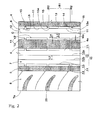
- FIG. 2 is an enlarged view of a left side portion of the tread portion shown in FIG. 1 .
- the pneumatic tire (hereinafter, also referred to simply as a "tire") of the present embodiment is advantageously used as, for example, a pneumatic tire for passenger cars.
- the tread portion 2 has at least one main groove 3 that continuously extends in the tire circumferential direction.
- the main groove 3 of the present embodiment includes a pair of center main grooves 4 that extend along and bilaterally to the tire equator C, and a pair of shoulder main grooves 5 that extend in regions outward of the center main grooves 4 in the tire axial direction.
- both the main grooves 4, 5 extend linearly along the tire circumferential direction.
- the main grooves 4, 5 thus formed enable water in the grooves to be smoothly drained backward in the tire rotating direction.
- the main groove 3 may extend zigzag or extend in a corrugated manner.
- a groove width W1 of each of the main grooves 4, 5 may be variously defined in a conventional manner.
- the groove width W1 for each main groove 3 preferably ranges, for example, from 2.0% of a tread contact width TW to 8.0% thereof.
- the land portions include a center land portion 6, a pair of middle land portions 7, and a pair of shoulder land portions 8.
- the center land portion 6 is defined between the pair of center main grooves 4.
- the middle land portions 7 are defined between the center main grooves 4 and the shoulder main grooves 5, respectively.
- the shoulder land portions 8 are defined between the shoulder main grooves 5 and ground contact ends Te, respectively.
- the shapes of the land portions of the tread portion 2 are not limited to such shapes, and the land portions may have various shapes.
- the "ground contact ends” are defined as outermost ground contact positions, in the tire axial direction, of the tire in a normal load state.
- the normal load state represents a state where, in a normal state where the tire is mounted to a normal rim, is inflated with air to a normal internal pressure, and is under no load, a normal load is applied to the tire and the tire is contacted with a flat ground surface with a camber angle of 0°.
- a distance, in the tire axial direction, between the ground contact ends Te, Te is defined as the tread contact width TW. Unless otherwise specified, dimensions of components of the tire and the like represent values measured in the normal state.
- the "normal rim” represents a rim that is defined, in a standard system including a standard with which the tire complies, by the standard for each tire, and is the "standard rim” in the JATMA standard, the "Design Rim” in the TRA standard, or the “Measuring Rim” in the ETRTO standard.
- the "normal internal pressure” represents an air pressure that is defined, in a standard system including a standard with which the tire complies, by the standard for each tire, and is the “maximum air pressure” in the JATMA standard, the maximum value recited in the table "TIRE LOAD LIMITS AT VARIOUS COLD INFLATION PRESSURES" in the TRA standard, or the “INFLATION PRESSURE” in the ETRTO standard.
- the normal internal pressure is 180 kPa.
- the "normal load” represents a load that is defined, in a standard system including a standard with which the tire complies, by the standard for each tire, and is the "maximum load capacity" in the JATMA standard, the "maximum value” recited in the table "TIRE LOAD LIMITS AT VARIOUS COLD INFLATION PRESSURES" in the TRA standard, or the "LOAD CAPACITY” in the ETRTO standard.
- the normal load is a load corresponding to 88% of the load described above.
- the center land portion 6 includes a sipe 10 that is obtained by cutting.
- the sipe 10 includes, for example, first sipes 11 and a second sipe 12.
- the first sipes 11 are disposed, for example, bilaterally to the tire equator C.
- the number of the first sipes 11 is plural, and the plurality of the first sipes 11 are spaced from each other in the tire circumferential direction.
- Each first sipe 11 includes a circumferential portion 13 and axial portions 14.
- the circumferential portion 13 linearly extends along the tire circumferential direction.
- stiffness of a pattern near the circumferential portions 13 of the center land portion 6 becomes uniform along the tire circumferential direction.
- the center land portion 6 includes regions R1, having a low stiffness, in which the first sipes 11 are formed, and regions R2 each of which is disposed between the first sipes 11 spaced from each other and has a high stiffness. Therefore, when the center land portion 6 contacts with a ground, for example, temporary shock wave is applied to air in the center main grooves 4 due to the regions R2 having a high stiffness, to prevent generation of standing wave in the center main grooves 4, thereby reducing pipe resonance. Accordingly, the pneumatic tire of the present invention has improved noise performance. In a case where each first sipe 11 is formed merely by the circumferential portion 13, a difference in stiffness between the regions R1 and the regions R2 is reduced, and an effect of allowing the temporary shock wave to prevent generation of the standing wave is reduced.
- the first sipes 11 are spaced from each other in the tire circumferential direction, thereby improving noise performance. Accordingly, since a groove volume of each center main groove 4 is not reduced, the tire of the present invention maintains advantageous drainage performance.
- a distance La, in the tire axial direction, between the circumferential portion 13 of each first sipe 11 and a groove edge 4e of the corresponding center main groove 4 preferably ranges from 2 mm to 6 mm.
- stiffness, in the tire axial direction, of a first outer portion which is positioned outward of the circumferential portion 13 of each first sipe 11 in the tire axial direction is excessively reduced, and a starting point of uneven wear may be generated.
- stiffness of the first outer portion, that is, stiffness of the regions R1 is enhanced, and a difference in stiffness between the regions R1 and the regions R2 is reduced.
- the distance La, in the tire axial direction, between the circumferential portion 13 and the groove edge 4e of the corresponding center main groove 4 more preferably ranges from 3 mm to 5 mm.
- the axial portions 14 are formed at the end portions 13e, 13e on both sides, respectively, of each circumferential portion 13. Thus, great shock wave can be temporarily applied to air in each center main groove 4 at the end portions 13e, 13e on both the sides of each circumferential portion 13.
- the axial portions 14 communicate with the center main grooves 4 in the present embodiment.
- the above-described effect can be more advantageously exerted.
- the axial portions 14 linearly extend along the tire axial direction. Due to the axial portions 14 thus formed, stiffness in the tire axial direction is assuredly maintained high in the regions R1. Therefore, generation of standing wave can be more assuredly prevented.
- an interruption portion 15 which does not have the sipe 10 is formed between the first sipes 11, 11 that are adjacent to each other in the tire circumferential direction.
- the interruption portion 15 allows stiffness of a pattern of the center land portion 6 to be assuredly maintained high.
- a length Lb, in the tire circumferential direction, of the interruption portion 15 preferably ranges from 2 mm to 10 mm.
- the length Lb of the interruption portion 15 is less than 2 mm, application of temporary shock wave to air flowing in the center main grooves 4 is reduced, whereby an effect of improving noise performance may be insufficient.
- the length Lb of the interruption portion 15 is greater than 10 mm, the application of the shock wave described above may continue for a long time, and standing wave may be generated due to the shock wave, whereby noise performance may be deteriorated. Therefore, the length Lb of the interruption portion 15 more preferably ranges from 3 mm to 9 mm.
- FIG. 3 shows an example of a ground contact surface Se under a normal load, and the ground contact surface Se is indicated by an imaginary line.
- the at least one interruption portion 15 always appears, in the tire circumferential direction, on the ground contact surface Se of the tread portion 2 in the land portion having the first sipes 11.
- the region R2 having a high stiffness in the tire circumferential direction and the region R1 having a stiffness less than the region R2 are always positioned on the ground contact surface Se. Therefore, the above-described effect is advantageously exerted, to further reduce noise.
- the number of the interruption portions 15 on the ground contact surface Se under the normal load is greater than five, the region R2 having a high stiffness is increased, and standing wave may be generated due to temporary shock wave. Accordingly, the number of the interruption portions 15 on the ground contact surface Se under the normal load is preferably less than or equal to four, and more preferably two.
- At least one interruption portion 15 is preferably positioned in at least one of the land portions bilaterally to each of the main grooves 4, 5.
- the second sipe 12 is formed, in the center land portion 6, inward of the first sipes 11 in the tire axial direction.
- the second sipe 12 linearly extends continuously in the tire circumferential direction.
- the second sipe 12 thus formed enables stiffness, in the tire axial direction, of the center land portion 6 to be reduced along the tire circumferential direction, to reduce exciting force applied from a road surface. Accordingly, noise performance is further improved.
- the second sipe 12 does not intersect the first sipes 11. Namely, in the present embodiment, the second sipe 12 is spaced from the first sipes 11 in the tire axial direction.
- the second sipe 12 thus formed prevents excessive reduction of the stiffness of the center land portion 6. Therefore, steering stability and wear resistance are assuredly maintained high.
- the second sipe 12 is disposed in the mid-position, in the tire axial direction, of the center land portion 6.
- stiffness in the tire axial direction is equally reduced on both sides, in the tire axial direction, of the center land portion 6. Therefore, exciting force applied from a road surface is equally dispersed, thereby improving noise performance.
- the second sipe 12 is disposed on the tire equator C.
- a distance L1 in the tire axial direction, between the first sipe 11 and the second sipe 12 preferably ranges from 4 mm to 10 mm.
- the distance L1 between the first sipe 11 and the second sipe 12 is greater than 10 mm, the stiffness, in the tire axial direction, of the center land portion 6 cannot be effectively reduced, and noise performance may not be improved.
- the distance L1 between the first sipe 11 and the second sipe 12 is less than 4 mm, wear resistance or steering stability may be deteriorated.
- each sipe 10 preferably ranges from 1.5 mm to 5.0 mm.
- the depth of each sipe 10 is less than 1.5 mm, for example, the stiffness of the regions R1 in the center land portion 6 cannot be reduced, and shock wave may be continuously applied to air in the center main grooves 4 to generate standing wave.
- the depth of each sipe 10 is greater than 5.0 mm, the stiffness of the center land portion 6 is excessively reduced, whereby steering stability may be deteriorated. Therefore, the depth of each sipe 10 more preferably ranges from 2.0 mm to 4.5 mm.
- the depth of each sipe 10 is preferably less than the depth (not shown) of the main groove 3 adjacent to the sipe 10, and more preferably ranges from 15% of the depth of the adjacent main groove 3 to 65% thereof.
- a width Wa of each sipe 10 is preferably less than or equal to 1.0 mm. Namely, when the width Wa of each sipe 10 is greater than 1.0 mm, the stiffness of the center land portion 6 is excessively reduced, and steering stability or wear resistance may be deteriorated. Therefore, the width Wa of each sipe 10 is more preferably less than or equal to 0.8 mm.
- the center land portion 6 does not include a groove that has one end connected to the center main groove 4, and has a groove width which is greater than 2 mm.
- the center land portion 6 has a groove having a groove width that is greater than 2 mm, pipe resonance in the center main grooves 4 may be excited due to pumping sound being generated in the grooves by contact with a road surface, and noise performance may be deteriorated.
- the center land portion 6 has the groove, the stiffness of the center land portion 6 is excessively reduced, whereby steering stability may be deteriorated. Therefore, when the center land portion 6 does not have a groove having a groove width that is greater than 2 mm, as in the present embodiment, noise performance and steering stability are assuredly maintained high.
- each middle land portion 7 also has the sipe 10 that includes the first sipes 11 and the second sipes 12.
- the first sipes 11 are formed on both sides, in the tire axial direction, of each middle land portion 7. Namely, the first sipes 11 are formed so as to be adjacent to the center main grooves 4 and the shoulder main grooves 5.
- temporary shock wave can be applied from both sides, in the tire axial direction, of each center main groove 4. Further, temporary shock wave can be applied to air in the shoulder main grooves 5. Therefore, noise performance is further improved.
- the sipes 10 of the middle land portions 7 will be described focusing on difference from the sipes 10 of the center land portion 6.
- the number of the second sipes 12 in each middle land portion 7 is two.
- the two second sipes 12 are an inner second sipe 12a, and an outer second sipe 12b disposed outward of the inner second sipe 12a in the tire axial direction.
- each middle land portion 7 has a width, in the tire axial direction, which is greater than the center land portion 6. Therefore, the number of the second sipes 12 in each middle land portion 7 is greater than the number of the second sipes 12 in the center land portion 6, whereby stiffness of the middle land portions 7 is reduced, and exciting force from a road surface is effectively reduced, to improve noise performance.
- a distance L2 in the tire axial direction, between the inner second sipe 12a and the outer second sipe 12b preferably ranges from 4 mm to 10 mm. Further, a pitch between the sipes 10, 10 adjacent to each other is more preferably uniform.
- Each shoulder land portion 8 has a plurality of shoulder transverse grooves 20 in order to enhance drainage performance, and the plurality of shoulder transverse grooves 20 extend from the ground contact ends Te inward in the tire axial direction and are arranged in the tire circumferential direction.
- each shoulder land portion 8 has a region having a high stiffness and a region having a low stiffness, which are formed along the tire circumferential direction. Namely, an effect obtained when the first sipes 11 are formed in the shoulder land portions 8, is small. Therefore, the shoulder land portions 8 do not have the first sipes 11.
- a contact pressure applied to each shoulder land portion 8 is less than a contact pressure applied to the center land portion 6 during straight running. Namely, exciting force applied to each shoulder land portion 8 from a road surface is less than exciting force applied to the center land portion 6 from the road surface. Therefore, in the present embodiment, the shoulder land portions 8 do not have the second sipe 12. Thus, the stiffness of the shoulder land portions 8 is assuredly maintained high, to improve wear resistance or steering stability. Thus, in the present embodiment, the shoulder land portions 8 do not have the first sipes 11 and the second sipes 12.
- the shoulder land portions 8 are not limited to those as described above.
- the shoulder land portions 8 may have the first sipes 11 and the second sipes 12.
- Pneumatic tires each having a fundamental pattern shown in FIG. 1 and the size of 235/45R18 were produced as sample tires according to the specifications indicated in Table 1. Noise performance, drainage performance, and steering stability of each of the sample tires were tested. Common specifications among the sample tires and test methods are as described below. In Comparative example 2 indicated in Table 1, depths of the center main grooves and the shoulder main grooves were less than depths of the center main grooves and the shoulder main grooves in other comparative examples and examples. All the grooves had the same groove width.
- the sample tires of each of examples and comparative examples were mounted to all the wheels of a passenger car having an engine displacement of 2000 cc, under the following conditions.
- the test vehicle was driven between A and B by one test driver so as to be coasted in a state where an engine was stopped and a gear was in a neutral position, in compliance with the ECE R117.
- a maximum noise level between A and B was calculated.
- Noise measurement tools S were mounted, at positions that were higher than the ground level by 1.2 ⁇ 0.02 m, bilaterally to the vehicle running center C-C, so as to be spaced from each other by 7.5 ⁇ 0.05 m.
- the results were evaluated based on a difference (dB (A)) from a noise level of Comparative example 1. The greater the value is, the better the performance is.
- a test driver drove the test vehicle at 80 km/h so as to run over a puddle, having a water depth of 10 mm and a length of 20 m, which was formed in a test course with an asphalt road surface and with a radius of 100 m.
- an average lateral acceleration (lateral G) applied to front wheels was calculated.
- the results are each indicated as an index that is obtained based on a value of Comparative example 1 being 100. The greater the index is, the better the performance is.
- a test driver drove the test vehicle so as to run on a test course with a dry asphalt road surface.
- sensory evaluation by the test driver was made for running characteristics associated with handling responsiveness, stiffness, grip performance, and the like, during cornering.
- the results are each indicated as a score that is obtained based on a value of Comparative example 1 being 100. The greater the score is, the better the steering stability is.
Landscapes
- Engineering & Computer Science (AREA)
- Mechanical Engineering (AREA)
- Tires In General (AREA)
Abstract
Description
- The present invention relates to pneumatic tires that enable improvement of noise performance without deteriorating drainage performance.
- In general, a tread portion of a pneumatic tire has main grooves that extend continuously in the tire circumferential direction in order to smoothly drain water on a road surface backward in the tire rotating direction. However, during running on a dry road surface, standing wave is generated in air that flows in the main grooves, to generate pipe resonance (see, for example, Japanese Laid-Open Patent Publication No.
2003-300403 - However, when the groove volume of the main groove is reduced, a problem arises that drainage performance is deteriorated. Thus, noise performance and drainage performance conflict with each other, and improvement of both the performances in a balanced manner is difficult.
- The present invention is made in view of the aforementioned situations, and a main object of the present invention is to provide a pneumatic tire that has a fundamental structure in which a land portion adjacent to a main groove includes an improved sipe and enables improvement of noise performance without deteriorating drainage performance.
- The present invention is directed to a pneumatic tire having a tread portion in which at least one main groove continuously extends in a tire circumferential direction, and at least one land portion is adjacent to the main groove. In the pneumatic tire, the land portion includes a sipe. The sipe includes a plurality of first sipes that are spaced from each other in the tire circumferential direction. Each of the first sipes includes: a circumferential portion that extends along the tire circumferential direction; and an axial portion that extends from at least one of end portions of the circumferential portion toward the main groove.
- In the pneumatic tire of the present invention, the axial portion preferably communicates with the main groove.
- In the pneumatic tire of the present invention, the axial portion is preferably formed on each of both the end portions of the circumferential portion in each first sipe.
- In the pneumatic tire of the present invention, it is preferable that the land portion has an interruption portion formed between the first sipes adjacent to each other in the tire circumferential direction, and the interruption portion has no sipes, and when, in a normal state where the tire is mounted to a normal rim, is inflated with air to a normal internal pressure, and is under no load, a normal load is applied to the tire, and the tire is contacted with a flat ground surface with a camber angle of 0° and is rotated once, at least one interruption portion always appears on a ground contact surface of the tread portion.
- In the pneumatic tire of the present invention, the sipe preferably includes a second sipe that continuously extends in the tire circumferential direction, and the second sipe is preferably formed so as not to intersect the first sipes.
- In the pneumatic tire of the present invention, a depth of the sipe preferably ranges from 1.5 mm to 5.0 mm.
- In the pneumatic tire of the present invention, a length, in the tire circumferential direction, of the interruption portion preferably ranges from 2 mm to 10 mm.
- In the pneumatic tire of the present invention, a distance, in a tire axial direction, between a groove edge of the main groove and the circumferential portion of each first sipe preferably ranges from 2 mm to 6 mm.
- In the pneumatic tire of the present invention, it is preferable that the land portion does not include a groove that has one end connected to the main groove, and has a groove width which is greater than 2 mm.
- In the pneumatic tire of the present invention, the land portion adjacent to the main groove includes a sipe. The sipe includes a plurality of first sipes spaced from each other in the tire circumferential direction. Each first sipe includes the circumferential portion that extends along the tire circumferential direction, and the axial portion that extends from at least one of end portions of the circumferential portion toward the main groove. Namely, the land portion includes regions which are disposed between the first sipes spaced from each other and have a high stiffness, and regions, having a low stiffness, in which the first sipes are formed. Therefore, when the land portion contacts with a ground, for example, temporary shock wave is applied to air in the main grooves due to the regions having a high stiffness, to prevent generation of standing wave in the main grooves, thereby reducing pipe resonance. Accordingly, in the pneumatic tire of the present invention, noise performance is improved.
-
-
FIG. 1 is a development of a tread portion according to one embodiment of the present invention; -
FIG. 2 is an enlarged view of a left side portion of the tread portion shown inFIG. 1 ; -
FIG. 3 is a plan view illustrating a ground contact surface of the tire under a normal load; -
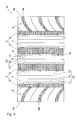
FIG. 4 is a development of a tread portion according to another embodiment of the present invention; -
FIG. 5 is a development of a tread portion of a tire according to a comparative example; -
FIG. 6 is a development of a tread portion of a tire according to still another comparative example; and -
FIG. 7 is a plan view schematically illustrating noise test conducted by an actually running car. - Hereinafter, an embodiment of the present invention will be described with reference to the drawings.
-
FIG. 1 is a development of atread portion 2 of a pneumatic tire according to one embodiment of the present invention.FIG. 2 is an enlarged view of a left side portion of the tread portion shown inFIG. 1 . The pneumatic tire (hereinafter, also referred to simply as a "tire") of the present embodiment is advantageously used as, for example, a pneumatic tire for passenger cars. - As shown in
FIG. 1 , thetread portion 2 has at least onemain groove 3 that continuously extends in the tire circumferential direction. Themain groove 3 of the present embodiment includes a pair of centermain grooves 4 that extend along and bilaterally to the tire equator C, and a pair of shouldermain grooves 5 that extend in regions outward of the centermain grooves 4 in the tire axial direction. - In the present embodiment, both the
main grooves main grooves main groove 3 may extend zigzag or extend in a corrugated manner. - A groove width W1 of each of the
main grooves tread portion 2, the groove width W1 for eachmain groove 3 preferably ranges, for example, from 2.0% of a tread contact width TW to 8.0% thereof. - In the
tread portion 2, a plurality of land portions are formed by themain grooves 3. In the present embodiment, the land portions include acenter land portion 6, a pair ofmiddle land portions 7, and a pair ofshoulder land portions 8. - The
center land portion 6 is defined between the pair of centermain grooves 4. Themiddle land portions 7 are defined between the centermain grooves 4 and the shouldermain grooves 5, respectively. Theshoulder land portions 8 are defined between the shouldermain grooves 5 and ground contact ends Te, respectively. The shapes of the land portions of thetread portion 2 are not limited to such shapes, and the land portions may have various shapes. - The "ground contact ends" are defined as outermost ground contact positions, in the tire axial direction, of the tire in a normal load state. The normal load state represents a state where, in a normal state where the tire is mounted to a normal rim, is inflated with air to a normal internal pressure, and is under no load, a normal load is applied to the tire and the tire is contacted with a flat ground surface with a camber angle of 0°. In the normal state, a distance, in the tire axial direction, between the ground contact ends Te, Te, is defined as the tread contact width TW. Unless otherwise specified, dimensions of components of the tire and the like represent values measured in the normal state.
- The "normal rim" represents a rim that is defined, in a standard system including a standard with which the tire complies, by the standard for each tire, and is the "standard rim" in the JATMA standard, the "Design Rim" in the TRA standard, or the "Measuring Rim" in the ETRTO standard. The "normal internal pressure" represents an air pressure that is defined, in a standard system including a standard with which the tire complies, by the standard for each tire, and is the "maximum air pressure" in the JATMA standard, the maximum value recited in the table "TIRE LOAD LIMITS AT VARIOUS COLD INFLATION PRESSURES" in the TRA standard, or the "INFLATION PRESSURE" in the ETRTO standard. When the tire is for passenger cars, the normal internal pressure is 180 kPa.
- The "normal load" represents a load that is defined, in a standard system including a standard with which the tire complies, by the standard for each tire, and is the "maximum load capacity" in the JATMA standard, the "maximum value" recited in the table "TIRE LOAD LIMITS AT VARIOUS COLD INFLATION PRESSURES" in the TRA standard, or the "LOAD CAPACITY" in the ETRTO standard. When the tire is for passenger cars, the normal load is a load corresponding to 88% of the load described above.
- In the present embodiment, the
center land portion 6 includes asipe 10 that is obtained by cutting. Thesipe 10 includes, for example,first sipes 11 and asecond sipe 12. - The
first sipes 11 are disposed, for example, bilaterally to the tire equator C. - As shown in
FIG. 2 , the number of thefirst sipes 11 is plural, and the plurality of thefirst sipes 11 are spaced from each other in the tire circumferential direction. - Each
first sipe 11 includes acircumferential portion 13 andaxial portions 14. - The
circumferential portion 13 linearly extends along the tire circumferential direction. Thus, stiffness of a pattern near thecircumferential portions 13 of thecenter land portion 6 becomes uniform along the tire circumferential direction. - In the present embodiment, the
axial portions 14 extend fromend portions 13e of thecircumferential portion 13 toward the centermain groove 4. Thus, thecenter land portion 6 includes regions R1, having a low stiffness, in which thefirst sipes 11 are formed, and regions R2 each of which is disposed between thefirst sipes 11 spaced from each other and has a high stiffness. Therefore, when thecenter land portion 6 contacts with a ground, for example, temporary shock wave is applied to air in the centermain grooves 4 due to the regions R2 having a high stiffness, to prevent generation of standing wave in the centermain grooves 4, thereby reducing pipe resonance. Accordingly, the pneumatic tire of the present invention has improved noise performance. In a case where eachfirst sipe 11 is formed merely by thecircumferential portion 13, a difference in stiffness between the regions R1 and the regions R2 is reduced, and an effect of allowing the temporary shock wave to prevent generation of the standing wave is reduced. - Thus, in the present invention, the
first sipes 11 are spaced from each other in the tire circumferential direction, thereby improving noise performance. Accordingly, since a groove volume of each centermain groove 4 is not reduced, the tire of the present invention maintains advantageous drainage performance. - A distance La, in the tire axial direction, between the
circumferential portion 13 of eachfirst sipe 11 and agroove edge 4e of the corresponding centermain groove 4 preferably ranges from 2 mm to 6 mm. In a case where the distance La is less than 2 mm, stiffness, in the tire axial direction, of a first outer portion which is positioned outward of thecircumferential portion 13 of eachfirst sipe 11 in the tire axial direction is excessively reduced, and a starting point of uneven wear may be generated. When the distance La is greater than 6 mm, stiffness of the first outer portion, that is, stiffness of the regions R1, is enhanced, and a difference in stiffness between the regions R1 and the regions R2 is reduced. Therefore, temporary shock wave is reduced, to reduce an effect of preventing generation of standing wave. Therefore, the distance La, in the tire axial direction, between thecircumferential portion 13 and thegroove edge 4e of the corresponding centermain groove 4 more preferably ranges from 3 mm to 5 mm. - The
axial portions 14 are formed at theend portions circumferential portion 13. Thus, great shock wave can be temporarily applied to air in each centermain groove 4 at theend portions circumferential portion 13. - The
axial portions 14 communicate with the centermain grooves 4 in the present embodiment. Thus, the above-described effect can be more advantageously exerted. - The
axial portions 14 linearly extend along the tire axial direction. Due to theaxial portions 14 thus formed, stiffness in the tire axial direction is assuredly maintained high in the regions R1. Therefore, generation of standing wave can be more assuredly prevented. - In the present embodiment, an
interruption portion 15 which does not have thesipe 10 is formed between thefirst sipes interruption portion 15 allows stiffness of a pattern of thecenter land portion 6 to be assuredly maintained high. - A length Lb, in the tire circumferential direction, of the
interruption portion 15 preferably ranges from 2 mm to 10 mm. When the length Lb of theinterruption portion 15 is less than 2 mm, application of temporary shock wave to air flowing in the centermain grooves 4 is reduced, whereby an effect of improving noise performance may be insufficient. When the length Lb of theinterruption portion 15 is greater than 10 mm, the application of the shock wave described above may continue for a long time, and standing wave may be generated due to the shock wave, whereby noise performance may be deteriorated. Therefore, the length Lb of theinterruption portion 15 more preferably ranges from 3 mm to 9 mm. -
FIG. 3 shows an example of a ground contact surface Se under a normal load, and the ground contact surface Se is indicated by an imaginary line. As shown inFIG. 3 , when the tire is rotated once under the normal load, the at least oneinterruption portion 15 always appears, in the tire circumferential direction, on the ground contact surface Se of thetread portion 2 in the land portion having thefirst sipes 11. Namely, in the land portion having thefirst sipes 11, the region R2 having a high stiffness in the tire circumferential direction and the region R1 having a stiffness less than the region R2 are always positioned on the ground contact surface Se. Therefore, the above-described effect is advantageously exerted, to further reduce noise. When the number of theinterruption portions 15 on the ground contact surface Se under the normal load, is greater than five, the region R2 having a high stiffness is increased, and standing wave may be generated due to temporary shock wave. Accordingly, the number of theinterruption portions 15 on the ground contact surface Se under the normal load is preferably less than or equal to four, and more preferably two. - On the ground contact surface Se under the normal load, at least one
interruption portion 15 is preferably positioned in at least one of the land portions bilaterally to each of themain grooves - As shown in
FIG. 2 , thesecond sipe 12 is formed, in thecenter land portion 6, inward of thefirst sipes 11 in the tire axial direction. - The
second sipe 12 linearly extends continuously in the tire circumferential direction. Thesecond sipe 12 thus formed enables stiffness, in the tire axial direction, of thecenter land portion 6 to be reduced along the tire circumferential direction, to reduce exciting force applied from a road surface. Accordingly, noise performance is further improved. - The
second sipe 12 does not intersect thefirst sipes 11. Namely, in the present embodiment, thesecond sipe 12 is spaced from thefirst sipes 11 in the tire axial direction. Thesecond sipe 12 thus formed prevents excessive reduction of the stiffness of thecenter land portion 6. Therefore, steering stability and wear resistance are assuredly maintained high. - The
second sipe 12 is disposed in the mid-position, in the tire axial direction, of thecenter land portion 6. Thus, stiffness in the tire axial direction is equally reduced on both sides, in the tire axial direction, of thecenter land portion 6. Therefore, exciting force applied from a road surface is equally dispersed, thereby improving noise performance. In the present embodiment, thesecond sipe 12 is disposed on the tire equator C. - A distance L1, in the tire axial direction, between the
first sipe 11 and thesecond sipe 12 preferably ranges from 4 mm to 10 mm. When the distance L1 between thefirst sipe 11 and thesecond sipe 12 is greater than 10 mm, the stiffness, in the tire axial direction, of thecenter land portion 6 cannot be effectively reduced, and noise performance may not be improved. When the distance L1 between thefirst sipe 11 and thesecond sipe 12 is less than 4 mm, wear resistance or steering stability may be deteriorated. - The depth (not shown) of each
sipe 10 preferably ranges from 1.5 mm to 5.0 mm. When the depth of eachsipe 10 is less than 1.5 mm, for example, the stiffness of the regions R1 in thecenter land portion 6 cannot be reduced, and shock wave may be continuously applied to air in the centermain grooves 4 to generate standing wave. When the depth of eachsipe 10 is greater than 5.0 mm, the stiffness of thecenter land portion 6 is excessively reduced, whereby steering stability may be deteriorated. Therefore, the depth of eachsipe 10 more preferably ranges from 2.0 mm to 4.5 mm. Further, the depth of eachsipe 10 is preferably less than the depth (not shown) of themain groove 3 adjacent to thesipe 10, and more preferably ranges from 15% of the depth of the adjacentmain groove 3 to 65% thereof. - A width Wa of each
sipe 10 is preferably less than or equal to 1.0 mm. Namely, when the width Wa of eachsipe 10 is greater than 1.0 mm, the stiffness of thecenter land portion 6 is excessively reduced, and steering stability or wear resistance may be deteriorated. Therefore, the width Wa of eachsipe 10 is more preferably less than or equal to 0.8 mm. - In the present embodiment, the
center land portion 6 does not include a groove that has one end connected to the centermain groove 4, and has a groove width which is greater than 2 mm. When thecenter land portion 6 has a groove having a groove width that is greater than 2 mm, pipe resonance in the centermain grooves 4 may be excited due to pumping sound being generated in the grooves by contact with a road surface, and noise performance may be deteriorated. Further, when thecenter land portion 6 has the groove, the stiffness of thecenter land portion 6 is excessively reduced, whereby steering stability may be deteriorated. Therefore, when thecenter land portion 6 does not have a groove having a groove width that is greater than 2 mm, as in the present embodiment, noise performance and steering stability are assuredly maintained high. - In the present embodiment, each
middle land portion 7 also has thesipe 10 that includes thefirst sipes 11 and thesecond sipes 12. Thefirst sipes 11 are formed on both sides, in the tire axial direction, of eachmiddle land portion 7. Namely, thefirst sipes 11 are formed so as to be adjacent to the centermain grooves 4 and the shouldermain grooves 5. Thus, temporary shock wave can be applied from both sides, in the tire axial direction, of each centermain groove 4. Further, temporary shock wave can be applied to air in the shouldermain grooves 5. Therefore, noise performance is further improved. Hereinafter, thesipes 10 of themiddle land portions 7 will be described focusing on difference from thesipes 10 of thecenter land portion 6. - The number of the
second sipes 12 in eachmiddle land portion 7 is two. In the present embodiment, the twosecond sipes 12 are an innersecond sipe 12a, and an outersecond sipe 12b disposed outward of the innersecond sipe 12a in the tire axial direction. In the present embodiment, eachmiddle land portion 7 has a width, in the tire axial direction, which is greater than thecenter land portion 6. Therefore, the number of thesecond sipes 12 in eachmiddle land portion 7 is greater than the number of thesecond sipes 12 in thecenter land portion 6, whereby stiffness of themiddle land portions 7 is reduced, and exciting force from a road surface is effectively reduced, to improve noise performance. - In order to advantageously exert such an effect, a distance L2, in the tire axial direction, between the inner
second sipe 12a and the outersecond sipe 12b preferably ranges from 4 mm to 10 mm. Further, a pitch between thesipes - Each
shoulder land portion 8 has a plurality of shouldertransverse grooves 20 in order to enhance drainage performance, and the plurality of shouldertransverse grooves 20 extend from the ground contact ends Te inward in the tire axial direction and are arranged in the tire circumferential direction. Thus, eachshoulder land portion 8 has a region having a high stiffness and a region having a low stiffness, which are formed along the tire circumferential direction. Namely, an effect obtained when thefirst sipes 11 are formed in theshoulder land portions 8, is small. Therefore, theshoulder land portions 8 do not have thefirst sipes 11. - A contact pressure applied to each
shoulder land portion 8 is less than a contact pressure applied to thecenter land portion 6 during straight running. Namely, exciting force applied to eachshoulder land portion 8 from a road surface is less than exciting force applied to thecenter land portion 6 from the road surface. Therefore, in the present embodiment, theshoulder land portions 8 do not have thesecond sipe 12. Thus, the stiffness of theshoulder land portions 8 is assuredly maintained high, to improve wear resistance or steering stability. Thus, in the present embodiment, theshoulder land portions 8 do not have thefirst sipes 11 and thesecond sipes 12. Theshoulder land portions 8 are not limited to those as described above. Theshoulder land portions 8 may have thefirst sipes 11 and thesecond sipes 12. - Although the pneumatic tire according to the present invention has been described above in detail, the present invention is not limited to the specific embodiment described above and various modifications can be made to implement the present invention.
- Pneumatic tires each having a fundamental pattern shown in
FIG. 1 and the size of 235/45R18 were produced as sample tires according to the specifications indicated in Table 1. Noise performance, drainage performance, and steering stability of each of the sample tires were tested. Common specifications among the sample tires and test methods are as described below. In Comparative example 2 indicated in Table 1, depths of the center main grooves and the shoulder main grooves were less than depths of the center main grooves and the shoulder main grooves in other comparative examples and examples. All the grooves had the same groove width. - Tread contact width TW: 19.0 mm
- Depth of center main groove: 8.2 mm (except for Comparative example 2)
- Depth of center main groove: 5.0 mm (for Comparative example 2)
- Depth of shoulder main groove: 8.2 mm (except for Comparative example 2)
- Depth of shoulder main groove: 5.0 mm (for Comparative example 2)
- Depth of shoulder transverse groove: 8.2 mm
- Width of sipe: 0.8 mm
- The sample tires of each of examples and comparative examples were mounted to all the wheels of a passenger car having an engine displacement of 2000 cc, under the following conditions. As shown in
FIG. 7 , the test vehicle was driven between A and B by one test driver so as to be coasted in a state where an engine was stopped and a gear was in a neutral position, in compliance with the ECE R117. A maximum noise level between A and B was calculated. Noise measurement tools S were mounted, at positions that were higher than the ground level by 1.2±0.02 m, bilaterally to the vehicle running center C-C, so as to be spaced from each other by 7.5±0.05 m. The results were evaluated based on a difference (dB (A)) from a noise level of Comparative example 1. The greater the value is, the better the performance is. - Rim: 8.0J×18
- Internal pressure: 176 kPa (average)
- Load: 4.60 kN (average)
- Speed between A and B: 70 km/h to 90 km/h
- A test driver drove the test vehicle at 80 km/h so as to run over a puddle, having a water depth of 10 mm and a length of 20 m, which was formed in a test course with an asphalt road surface and with a radius of 100 m. At this time, an average lateral acceleration (lateral G) applied to front wheels was calculated. The results are each indicated as an index that is obtained based on a value of Comparative example 1 being 100. The greater the index is, the better the performance is.
- A test driver drove the test vehicle so as to run on a test course with a dry asphalt road surface. At this time, sensory evaluation by the test driver was made for running characteristics associated with handling responsiveness, stiffness, grip performance, and the like, during cornering. The results are each indicated as a score that is obtained based on a value of Comparative example 1 being 100. The greater the score is, the better the steering stability is.
- The results of the test are indicated in Table 1.


- The results of the test indicate that the tires of examples are significantly improved as compared to the tires of comparative examples.
Claims (9)
- A pneumatic tire having a tread portion (2) in which at least one main groove (3) continuously extends in a tire circumferential direction, and at least one land portion (6, 7, 8) is adjacent to the main groove (3), wherein
the land portion (6, 7, 8) includes a sipe (10),
the sipe (10) includes a plurality of first sipes (11) that are spaced from each other in the tire circumferential direction, and
each of the first sipes (11) includes: a circumferential portion (13) that extends along the tire circumferential direction; and an axial portion (14) that extends from at least one of end portions (13e) of the circumferential portion (13) toward the main groove (3). - The pneumatic tire according to claim 1, wherein the axial portion (14) communicates with the main groove (3).
- The pneumatic tire according to claim 1 or 2, wherein the axial portion (14) is formed on each of both the end portions (13e) of the circumferential portion (13) in each first sipe (11).
- The pneumatic tire according to one of claims 1 to 3, wherein
the land portion (6, 7, 8) has an interruption portion (15) formed between the first sipes (11) adjacent to each other in the tire circumferential direction, and the interruption portion (15) has no sipes (10), and
when, in a normal state where the tire is mounted to a normal rim, is inflated with air to a normal internal pressure, and is under no load, a normal load is applied to the tire, and the tire is contacted with a flat ground surface with a camber angle of 0° and is rotated once, at least one interruption portion (15) always appears on a ground contact surface (Se) of the tread portion (2). - The pneumatic tire according to one of claims 1 to 4, wherein
the sipe (10) includes a second sipe (12) that continuously extends in the tire circumferential direction, and
the second sipe (12) is formed so as not to intersect the first sipes (11). - The pneumatic tire according to one of claims 1 to 5, wherein a depth of the sipe (10) ranges from 1.5 mm to 5.0 mm.
- The pneumatic tire according to one of claims 4 to 6, wherein a length (Lb), in the tire circumferential direction, of the interruption portion (15) ranges from 2 mm to 10 mm.
- The pneumatic tire according to one of claims 1 to 7, wherein a distance (La), in a tire axial direction, between a groove edge (4e) of the main groove (3) and the circumferential portion (13) of each first sipe (11) ranges from 2 mm to 6 mm.
- The pneumatic tire according to one of claims 1 to 8, wherein the land portion (6, 7, 8) does not include a groove that has one end connected to the main groove (3), and has a groove width which is greater than 2 mm.
Applications Claiming Priority (1)
| Application Number | Priority Date | Filing Date | Title |
|---|---|---|---|
| JP2013188652A JP6130760B2 (en) | 2013-09-11 | 2013-09-11 | Pneumatic tire |
Publications (2)
| Publication Number | Publication Date |
|---|---|
| EP2848433A1 true EP2848433A1 (en) | 2015-03-18 |
| EP2848433B1 EP2848433B1 (en) | 2016-07-27 |
Family
ID=51301147
Family Applications (1)
| Application Number | Title | Priority Date | Filing Date |
|---|---|---|---|
| EP14180460.9A Active EP2848433B1 (en) | 2013-09-11 | 2014-08-11 | Pneumatic tire |
Country Status (3)
| Country | Link |
|---|---|
| EP (1) | EP2848433B1 (en) |
| JP (1) | JP6130760B2 (en) |
| CN (1) | CN104417283B (en) |
Citations (5)
| Publication number | Priority date | Publication date | Assignee | Title |
|---|---|---|---|---|
| JP2003300403A (en) | 2002-04-10 | 2003-10-21 | Toyo Tire & Rubber Co Ltd | Pneumatic tire |
| EP2014485A1 (en) * | 2006-03-31 | 2009-01-14 | Bridgestone Corporation | Pneumatic tire |
| FR2926037A1 (en) * | 2008-01-09 | 2009-07-10 | Michelin Soc Tech | DEVICE FOR ROLLING BAND. |
| WO2012049274A1 (en) * | 2010-10-14 | 2012-04-19 | Societe De Technologie Michelin | Improvement to noise attentuator devices for tyres |
| EP2463120A1 (en) * | 2009-08-07 | 2012-06-13 | Bridgestone Corporation | Tire |
Family Cites Families (7)
| Publication number | Priority date | Publication date | Assignee | Title |
|---|---|---|---|---|
| JPS5244901A (en) * | 1975-10-04 | 1977-04-08 | Bridgestone Corp | High durable tread pattern of two grooves rip type pneumtic tire |
| JPS61200008A (en) * | 1985-03-01 | 1986-09-04 | Sumitomo Rubber Ind Ltd | Low noise bias tire |
| JP3391690B2 (en) * | 1998-03-30 | 2003-03-31 | 住友ゴム工業株式会社 | Pneumatic tire |
| EP1372988B1 (en) * | 2001-03-30 | 2005-12-07 | PIRELLI PNEUMATICI S.p.A. | Tread pattern for car tire |
| JP4713785B2 (en) * | 2001-08-23 | 2011-06-29 | 株式会社ブリヂストン | Pneumatic tire |
| JP4873988B2 (en) * | 2006-05-11 | 2012-02-08 | 株式会社ブリヂストン | Pneumatic tire |
| JP5513082B2 (en) * | 2009-11-13 | 2014-06-04 | 株式会社ブリヂストン | Pneumatic tire |
-
2013
- 2013-09-11 JP JP2013188652A patent/JP6130760B2/en active Active
-
2014
- 2014-08-11 EP EP14180460.9A patent/EP2848433B1/en active Active
- 2014-09-03 CN CN201410446850.4A patent/CN104417283B/en active Active
Patent Citations (5)
| Publication number | Priority date | Publication date | Assignee | Title |
|---|---|---|---|---|
| JP2003300403A (en) | 2002-04-10 | 2003-10-21 | Toyo Tire & Rubber Co Ltd | Pneumatic tire |
| EP2014485A1 (en) * | 2006-03-31 | 2009-01-14 | Bridgestone Corporation | Pneumatic tire |
| FR2926037A1 (en) * | 2008-01-09 | 2009-07-10 | Michelin Soc Tech | DEVICE FOR ROLLING BAND. |
| EP2463120A1 (en) * | 2009-08-07 | 2012-06-13 | Bridgestone Corporation | Tire |
| WO2012049274A1 (en) * | 2010-10-14 | 2012-04-19 | Societe De Technologie Michelin | Improvement to noise attentuator devices for tyres |
Also Published As
| Publication number | Publication date |
|---|---|
| EP2848433B1 (en) | 2016-07-27 |
| JP2015054601A (en) | 2015-03-23 |
| CN104417283B (en) | 2018-06-05 |
| CN104417283A (en) | 2015-03-18 |
| JP6130760B2 (en) | 2017-05-17 |
Similar Documents
| Publication | Publication Date | Title |
|---|---|---|
| US9994077B2 (en) | Pneumatic tire | |
| US9452642B2 (en) | Pneumatic tire | |
| JP6420547B2 (en) | Pneumatic tire | |
| EP3000622B1 (en) | Pneumatic tire | |
| JP6674414B2 (en) | Pneumatic tire | |
| RU2655242C2 (en) | Pneumatic tyre | |
| US9096099B2 (en) | Pneumatic tire | |
| EP3078506B1 (en) | Pneumatic tire | |
| US10272725B2 (en) | Pneumatic tire | |
| CN108688411B (en) | Pneumatic tire | |
| JP6819133B2 (en) | tire | |
| US9056530B2 (en) | Pneumatic tire | |
| JP6769280B2 (en) | tire | |
| JP2017170939A (en) | Pneumatic tire | |
| JP7547863B2 (en) | tire | |
| US20180339557A1 (en) | Tire | |
| JP6097261B2 (en) | Pneumatic tire | |
| JP5830079B2 (en) | Pneumatic tire | |
| JP2013079006A (en) | Pneumatic tire | |
| JP2010247549A (en) | Pneumatic tire | |
| JP2018076001A (en) | tire | |
| CN112829520B (en) | Tire with a tire body | |
| EP3388254A1 (en) | Tire | |
| JP2017030639A (en) | Pneumatic tire | |
| CN110588249B (en) | Tire with a tire body |
Legal Events
| Date | Code | Title | Description |
|---|---|---|---|
| PUAI | Public reference made under article 153(3) epc to a published international application that has entered the european phase |
Free format text: ORIGINAL CODE: 0009012 |
|
| 17P | Request for examination filed |
Effective date: 20140811 |
|
| AK | Designated contracting states |
Kind code of ref document: A1 Designated state(s): AL AT BE BG CH CY CZ DE DK EE ES FI FR GB GR HR HU IE IS IT LI LT LU LV MC MK MT NL NO PL PT RO RS SE SI SK SM TR |
|
| AX | Request for extension of the european patent |
Extension state: BA ME |
|
| R17P | Request for examination filed (corrected) |
Effective date: 20150723 |
|
| RBV | Designated contracting states (corrected) |
Designated state(s): AL AT BE BG CH CY CZ DE DK EE ES FI FR GB GR HR HU IE IS IT LI LT LU LV MC MK MT NL NO PL PT RO RS SE SI SK SM TR |
|
| GRAP | Despatch of communication of intention to grant a patent |
Free format text: ORIGINAL CODE: EPIDOSNIGR1 |
|
| INTG | Intention to grant announced |
Effective date: 20160309 |
|
| GRAS | Grant fee paid |
Free format text: ORIGINAL CODE: EPIDOSNIGR3 |
|
| GRAA | (expected) grant |
Free format text: ORIGINAL CODE: 0009210 |
|
| AK | Designated contracting states |
Kind code of ref document: B1 Designated state(s): AL AT BE BG CH CY CZ DE DK EE ES FI FR GB GR HR HU IE IS IT LI LT LU LV MC MK MT NL NO PL PT RO RS SE SI SK SM TR |
|
| REG | Reference to a national code |
Ref country code: GB Ref legal event code: FG4D |
|
| REG | Reference to a national code |
Ref country code: CH Ref legal event code: EP |
|
| REG | Reference to a national code |
Ref country code: AT Ref legal event code: REF Ref document number: 815487 Country of ref document: AT Kind code of ref document: T Effective date: 20160815 |
|
| REG | Reference to a national code |
Ref country code: FR Ref legal event code: PLFP Year of fee payment: 3 |
|
| REG | Reference to a national code |
Ref country code: IE Ref legal event code: FG4D |
|
| REG | Reference to a national code |
Ref country code: DE Ref legal event code: R096 Ref document number: 602014002852 Country of ref document: DE |
|
| REG | Reference to a national code |
Ref country code: LT Ref legal event code: MG4D |
|
| REG | Reference to a national code |
Ref country code: NL Ref legal event code: MP Effective date: 20160727 |
|
| REG | Reference to a national code |
Ref country code: AT Ref legal event code: MK05 Ref document number: 815487 Country of ref document: AT Kind code of ref document: T Effective date: 20160727 |
|
| PG25 | Lapsed in a contracting state [announced via postgrant information from national office to epo] |
Ref country code: BE Free format text: LAPSE BECAUSE OF NON-PAYMENT OF DUE FEES Effective date: 20160831 |
|
| PG25 | Lapsed in a contracting state [announced via postgrant information from national office to epo] |
Ref country code: HR Free format text: LAPSE BECAUSE OF FAILURE TO SUBMIT A TRANSLATION OF THE DESCRIPTION OR TO PAY THE FEE WITHIN THE PRESCRIBED TIME-LIMIT Effective date: 20160727 Ref country code: RS Free format text: LAPSE BECAUSE OF FAILURE TO SUBMIT A TRANSLATION OF THE DESCRIPTION OR TO PAY THE FEE WITHIN THE PRESCRIBED TIME-LIMIT Effective date: 20160727 Ref country code: IT Free format text: LAPSE BECAUSE OF FAILURE TO SUBMIT A TRANSLATION OF THE DESCRIPTION OR TO PAY THE FEE WITHIN THE PRESCRIBED TIME-LIMIT Effective date: 20160727 Ref country code: FI Free format text: LAPSE BECAUSE OF FAILURE TO SUBMIT A TRANSLATION OF THE DESCRIPTION OR TO PAY THE FEE WITHIN THE PRESCRIBED TIME-LIMIT Effective date: 20160727 Ref country code: NO Free format text: LAPSE BECAUSE OF FAILURE TO SUBMIT A TRANSLATION OF THE DESCRIPTION OR TO PAY THE FEE WITHIN THE PRESCRIBED TIME-LIMIT Effective date: 20161027 Ref country code: NL Free format text: LAPSE BECAUSE OF FAILURE TO SUBMIT A TRANSLATION OF THE DESCRIPTION OR TO PAY THE FEE WITHIN THE PRESCRIBED TIME-LIMIT Effective date: 20160727 Ref country code: LT Free format text: LAPSE BECAUSE OF FAILURE TO SUBMIT A TRANSLATION OF THE DESCRIPTION OR TO PAY THE FEE WITHIN THE PRESCRIBED TIME-LIMIT Effective date: 20160727 Ref country code: IS Free format text: LAPSE BECAUSE OF FAILURE TO SUBMIT A TRANSLATION OF THE DESCRIPTION OR TO PAY THE FEE WITHIN THE PRESCRIBED TIME-LIMIT Effective date: 20161127 |
|
| PG25 | Lapsed in a contracting state [announced via postgrant information from national office to epo] |
Ref country code: SE Free format text: LAPSE BECAUSE OF FAILURE TO SUBMIT A TRANSLATION OF THE DESCRIPTION OR TO PAY THE FEE WITHIN THE PRESCRIBED TIME-LIMIT Effective date: 20160727 Ref country code: AT Free format text: LAPSE BECAUSE OF FAILURE TO SUBMIT A TRANSLATION OF THE DESCRIPTION OR TO PAY THE FEE WITHIN THE PRESCRIBED TIME-LIMIT Effective date: 20160727 Ref country code: ES Free format text: LAPSE BECAUSE OF FAILURE TO SUBMIT A TRANSLATION OF THE DESCRIPTION OR TO PAY THE FEE WITHIN THE PRESCRIBED TIME-LIMIT Effective date: 20160727 Ref country code: BE Free format text: LAPSE BECAUSE OF FAILURE TO SUBMIT A TRANSLATION OF THE DESCRIPTION OR TO PAY THE FEE WITHIN THE PRESCRIBED TIME-LIMIT Effective date: 20160727 Ref country code: LV Free format text: LAPSE BECAUSE OF FAILURE TO SUBMIT A TRANSLATION OF THE DESCRIPTION OR TO PAY THE FEE WITHIN THE PRESCRIBED TIME-LIMIT Effective date: 20160727 Ref country code: PT Free format text: LAPSE BECAUSE OF FAILURE TO SUBMIT A TRANSLATION OF THE DESCRIPTION OR TO PAY THE FEE WITHIN THE PRESCRIBED TIME-LIMIT Effective date: 20161128 Ref country code: PL Free format text: LAPSE BECAUSE OF FAILURE TO SUBMIT A TRANSLATION OF THE DESCRIPTION OR TO PAY THE FEE WITHIN THE PRESCRIBED TIME-LIMIT Effective date: 20160727 Ref country code: GR Free format text: LAPSE BECAUSE OF FAILURE TO SUBMIT A TRANSLATION OF THE DESCRIPTION OR TO PAY THE FEE WITHIN THE PRESCRIBED TIME-LIMIT Effective date: 20161028 |
|
| PG25 | Lapsed in a contracting state [announced via postgrant information from national office to epo] |
Ref country code: EE Free format text: LAPSE BECAUSE OF FAILURE TO SUBMIT A TRANSLATION OF THE DESCRIPTION OR TO PAY THE FEE WITHIN THE PRESCRIBED TIME-LIMIT Effective date: 20160727 Ref country code: MC Free format text: LAPSE BECAUSE OF FAILURE TO SUBMIT A TRANSLATION OF THE DESCRIPTION OR TO PAY THE FEE WITHIN THE PRESCRIBED TIME-LIMIT Effective date: 20160727 Ref country code: RO Free format text: LAPSE BECAUSE OF FAILURE TO SUBMIT A TRANSLATION OF THE DESCRIPTION OR TO PAY THE FEE WITHIN THE PRESCRIBED TIME-LIMIT Effective date: 20160727 |
|
| REG | Reference to a national code |
Ref country code: DE Ref legal event code: R097 Ref document number: 602014002852 Country of ref document: DE |
|
| PG25 | Lapsed in a contracting state [announced via postgrant information from national office to epo] |
Ref country code: SK Free format text: LAPSE BECAUSE OF FAILURE TO SUBMIT A TRANSLATION OF THE DESCRIPTION OR TO PAY THE FEE WITHIN THE PRESCRIBED TIME-LIMIT Effective date: 20160727 Ref country code: BG Free format text: LAPSE BECAUSE OF FAILURE TO SUBMIT A TRANSLATION OF THE DESCRIPTION OR TO PAY THE FEE WITHIN THE PRESCRIBED TIME-LIMIT Effective date: 20161027 Ref country code: SM Free format text: LAPSE BECAUSE OF FAILURE TO SUBMIT A TRANSLATION OF THE DESCRIPTION OR TO PAY THE FEE WITHIN THE PRESCRIBED TIME-LIMIT Effective date: 20160727 Ref country code: DK Free format text: LAPSE BECAUSE OF FAILURE TO SUBMIT A TRANSLATION OF THE DESCRIPTION OR TO PAY THE FEE WITHIN THE PRESCRIBED TIME-LIMIT Effective date: 20160727 Ref country code: CZ Free format text: LAPSE BECAUSE OF FAILURE TO SUBMIT A TRANSLATION OF THE DESCRIPTION OR TO PAY THE FEE WITHIN THE PRESCRIBED TIME-LIMIT Effective date: 20160727 |
|
| REG | Reference to a national code |
Ref country code: IE Ref legal event code: MM4A |
|
| PLBE | No opposition filed within time limit |
Free format text: ORIGINAL CODE: 0009261 |
|
| STAA | Information on the status of an ep patent application or granted ep patent |
Free format text: STATUS: NO OPPOSITION FILED WITHIN TIME LIMIT |
|
| 26N | No opposition filed |
Effective date: 20170502 |
|
| PG25 | Lapsed in a contracting state [announced via postgrant information from national office to epo] |
Ref country code: IE Free format text: LAPSE BECAUSE OF NON-PAYMENT OF DUE FEES Effective date: 20160811 |
|
| REG | Reference to a national code |
Ref country code: FR Ref legal event code: PLFP Year of fee payment: 4 |
|
| PG25 | Lapsed in a contracting state [announced via postgrant information from national office to epo] |
Ref country code: SI Free format text: LAPSE BECAUSE OF FAILURE TO SUBMIT A TRANSLATION OF THE DESCRIPTION OR TO PAY THE FEE WITHIN THE PRESCRIBED TIME-LIMIT Effective date: 20160727 Ref country code: LU Free format text: LAPSE BECAUSE OF NON-PAYMENT OF DUE FEES Effective date: 20160811 |
|
| REG | Reference to a national code |
Ref country code: CH Ref legal event code: PL |
|
| PG25 | Lapsed in a contracting state [announced via postgrant information from national office to epo] |
Ref country code: LI Free format text: LAPSE BECAUSE OF NON-PAYMENT OF DUE FEES Effective date: 20170831 Ref country code: CH Free format text: LAPSE BECAUSE OF NON-PAYMENT OF DUE FEES Effective date: 20170831 |
|
| PG25 | Lapsed in a contracting state [announced via postgrant information from national office to epo] |
Ref country code: HU Free format text: LAPSE BECAUSE OF FAILURE TO SUBMIT A TRANSLATION OF THE DESCRIPTION OR TO PAY THE FEE WITHIN THE PRESCRIBED TIME-LIMIT; INVALID AB INITIO Effective date: 20140811 |
|
| PG25 | Lapsed in a contracting state [announced via postgrant information from national office to epo] |
Ref country code: CY Free format text: LAPSE BECAUSE OF FAILURE TO SUBMIT A TRANSLATION OF THE DESCRIPTION OR TO PAY THE FEE WITHIN THE PRESCRIBED TIME-LIMIT Effective date: 20160727 Ref country code: MT Free format text: LAPSE BECAUSE OF NON-PAYMENT OF DUE FEES Effective date: 20160831 Ref country code: MK Free format text: LAPSE BECAUSE OF FAILURE TO SUBMIT A TRANSLATION OF THE DESCRIPTION OR TO PAY THE FEE WITHIN THE PRESCRIBED TIME-LIMIT Effective date: 20160727 |
|
| REG | Reference to a national code |
Ref country code: FR Ref legal event code: PLFP Year of fee payment: 5 |
|
| PG25 | Lapsed in a contracting state [announced via postgrant information from national office to epo] |
Ref country code: AL Free format text: LAPSE BECAUSE OF FAILURE TO SUBMIT A TRANSLATION OF THE DESCRIPTION OR TO PAY THE FEE WITHIN THE PRESCRIBED TIME-LIMIT Effective date: 20160727 Ref country code: TR Free format text: LAPSE BECAUSE OF FAILURE TO SUBMIT A TRANSLATION OF THE DESCRIPTION OR TO PAY THE FEE WITHIN THE PRESCRIBED TIME-LIMIT Effective date: 20160727 |
|
| GBPC | Gb: european patent ceased through non-payment of renewal fee |
Effective date: 20180811 |
|
| PG25 | Lapsed in a contracting state [announced via postgrant information from national office to epo] |
Ref country code: GB Free format text: LAPSE BECAUSE OF NON-PAYMENT OF DUE FEES Effective date: 20180811 |
|
| P01 | Opt-out of the competence of the unified patent court (upc) registered |
Effective date: 20230510 |
|
| PGFP | Annual fee paid to national office [announced via postgrant information from national office to epo] |
Ref country code: DE Payment date: 20250702 Year of fee payment: 12 |
|
| PGFP | Annual fee paid to national office [announced via postgrant information from national office to epo] |
Ref country code: FR Payment date: 20250703 Year of fee payment: 12 |