EP2848406A2 - Rotary screen printing press - Google Patents
Rotary screen printing press Download PDFInfo
- Publication number
- EP2848406A2 EP2848406A2 EP14184605.5A EP14184605A EP2848406A2 EP 2848406 A2 EP2848406 A2 EP 2848406A2 EP 14184605 A EP14184605 A EP 14184605A EP 2848406 A2 EP2848406 A2 EP 2848406A2
- Authority
- EP
- European Patent Office
- Prior art keywords
- squeegee
- screen
- rotary
- supporting
- plate
- Prior art date
- Legal status (The legal status is an assumption and is not a legal conclusion. Google has not performed a legal analysis and makes no representation as to the accuracy of the status listed.)
- Withdrawn
Links
Images


Classifications
-
- B—PERFORMING OPERATIONS; TRANSPORTING
- B41—PRINTING; LINING MACHINES; TYPEWRITERS; STAMPS
- B41F—PRINTING MACHINES OR PRESSES
- B41F15/00—Screen printers
- B41F15/14—Details
- B41F15/44—Squeegees or doctors
- B41F15/46—Squeegees or doctors with two or more operative parts
-
- B—PERFORMING OPERATIONS; TRANSPORTING
- B41—PRINTING; LINING MACHINES; TYPEWRITERS; STAMPS
- B41F—PRINTING MACHINES OR PRESSES
- B41F15/00—Screen printers
- B41F15/08—Machines
- B41F15/0804—Machines for printing sheets
- B41F15/0809—Machines for printing sheets with cylindrical or belt-like screens
-
- B—PERFORMING OPERATIONS; TRANSPORTING
- B41—PRINTING; LINING MACHINES; TYPEWRITERS; STAMPS
- B41F—PRINTING MACHINES OR PRESSES
- B41F15/00—Screen printers
- B41F15/14—Details
- B41F15/34—Screens, Frames; Holders therefor
- B41F15/38—Screens, Frames; Holders therefor curved
-
- B—PERFORMING OPERATIONS; TRANSPORTING
- B41—PRINTING; LINING MACHINES; TYPEWRITERS; STAMPS
- B41F—PRINTING MACHINES OR PRESSES
- B41F15/00—Screen printers
- B41F15/14—Details
- B41F15/44—Squeegees or doctors
-
- B—PERFORMING OPERATIONS; TRANSPORTING
- B41—PRINTING; LINING MACHINES; TYPEWRITERS; STAMPS
- B41F—PRINTING MACHINES OR PRESSES
- B41F15/00—Screen printers
- B41F15/08—Machines
-
- B—PERFORMING OPERATIONS; TRANSPORTING
- B41—PRINTING; LINING MACHINES; TYPEWRITERS; STAMPS
- B41F—PRINTING MACHINES OR PRESSES
- B41F15/00—Screen printers
- B41F15/14—Details
Definitions
- the present invention relates to a rotary screen printing press which performs screen printing by using a cylindrical screen plate.
- Rotary screen printing presses utilizing a rotary screen unit have heretofore been known as high-speed printing apparatuses for printing objects made from a wide range of materials such as cloth and paper.
- the rotary screen printing presses employ a printing method involving pushing ink with a squeegee through through-holes formed in the plate surface of a screen plate formed in a cylindrical shape to transfer the forced ink onto a printing object.
- the squeegee in such a rotary screen printing press, includes a squeegee body (blade) configured to push ink, and a support (squeegee bar) supporting the blade.
- a squeegee body configured to push ink
- a support squeegee bar
- the squeegee is positioned inside a rotary screen, and opposite end portions of the squeegee bar are fixed to squeegee supporting means.
- the rotary screen refers to a screen plate formed in a cylindrical shape and having end rings attached to the opposite ends thereof as supporting members.
- a conventional rotary screen printing press as described above includes screen-plate supporting means for supporting a rotary screen in such a way that the rotary screen can be engaged with and disengaged from an impression cylinder, and squeegee supporting means for supporting the opposite ends of a squeegee bar in such a way that a blade can be engaged with and disengaged from the inner peripheral surface of the rotary screen (see Patent Literature 1, for example).
- Patent Literature 1 Japanese Patent Application Publication No. 2008-201119
- Patent Literature 2 Japanese Patent Application Publication No. Hei 7-241977
- rotary screen printing presses are also required to adjust the angles of their squeegees.
- a printing object comes into contact with the peripheral surface of the rotary screen, or a cylindrical body.
- a problem may occur in that the adjustment of the squeegee angle displaces the tip of the squeegee from the contact position and deteriorates the print quality.
- an object of the present invention is to provide a rotary screen printing press capable of squeegee angle adjustment and capable of high quality printing.
- a rotary screen printing press for solving the above-mentioned problem includes: a screen plate formed in a cylindrical shape; a squeegee; squeegee supporting means for supporting the squeegee; and an angle adjustment unit configured to adjust an angle of the squeegee, in which the squeegee supporting means includes an arm swingably supported and supporting the angle adjustment unit, a squeegee position adjustment unit configured to adjust a position of a center of swinging movement of the arm, and a stopper part configured to limit a direction of the movement of the arm, and the squeegee position adjustment unit and the stopper part cooperate with each other to move a tip of the squeegee along a tangent line of an impression cylinder at a position at which the screen plate and the squeegee contact each other.
- the stopper part includes a contact surface formed as a flat surface, and a contact member configured to contact the contact surface, and the center of the swinging movement of the arm and the contact surface are arranged on the tangent line of the impression cylinder at the position at which the screen plate and the squeegee contact each other.
- the rotary screen printing press According to the rotary screen printing press according to the present invention, it is possible to adjust the angle of the squeegee in accordance with printing conditions while maintaining the print quality. Thus, high quality printing can be performed constantly.
- the rotary screen printing press includes an impression cylinder 100 and a rotary screen unit 200.
- the impression cylinder 100 is rotatably supported between left and right machine frames 101, 101.
- a notched portion is formed in the outer peripheral surface of the impression cylinder 100 along the axial direction of the impression cylinder 100.
- There are multiple notched portions (e.g. two in this embodiment) formed at an equal interval in the circumferential direction of the impression cylinder 100.
- the impression cylinder 100 includes gripper units (holding portions) not shown configured to grip and hold a tip of a sheet which is a printing object.
- the rotary screen unit 200 includes a rotary screen 201 and a squeegee 213.
- the rotary screen 201 includes a screen plate 201A and annular end rings 201B, 201B fixed to opposite ends (left and right ends in Fig. 2 ) of the screen plate 201A, respectively.
- the screen plate 201A is a cylindrical body being a cylindrical thin plate material through which fine holes are etched in a given pattern.
- Each end ring 201B is a member for reinforcing the screen plate 201A.
- a protruding portion not shown (hereinafter, “end-ring protruding portion"), multiple (two in this embodiment) notched portions not shown (hereinafter, “end-ring notched portions), and a pin groove not shown are formed on and in each end ring 201B.
- the end-ring protruding portion is a flange protruding radially outward from the outer peripheral surface of an end portion on the opposite side from the screen plate 201A in the axial direction of the end ring 201B.
- the multiple end-ring notched portions are provided in this end-ring protruding portion at an equal interval in the circumferential direction.
- the pin groove is provided in the end-ring protruding portion between the adjacent end-ring notched portions and formed by cutting the outer peripheral surface of the end-ring protruding portion in a U-shape toward the axis.
- These end rings 201B are supported on bearing members 202.
- bearing-member protruding portions multiple (two in this embodiment) protruding portions not shown (hereinafter, "bearing-member protruding portions") are formed on each bearing member 202, and a pin not shown is provided thereon as well.
- the bearing-member protruding portions protrude radially inward from the inner peripheral surface of the bearing member 202 on the end ring 201B side in the axial direction thereof and provided at an equal interval in the circumferential direction (the same interval as that of the end-ring notched portions).
- the shape of the bearing-member protruding portions is designed such that the bearing-member protruding portions can pass through the end-ring notched portions in the radial direction.
- the pin is fixed to one of the bearing-member protruding portions in such a way as to be engaged with the pin groove in the end ring 201B when the end ring 201B is attached to the bearing member 202.
- the rotary screen 201 is moved in the axial direction with the end-ring notched portions of the end ring 201B and the bearing-member protruding portions of the bearing member 202 aligned with each other in the circumferential direction, to thereby insert the end ring 201B into the hollow portion of the bearing member 202 to such an extent that the bearing-member protruding portions and the pin are positioned inside the end-ring protruding portion in the axial direction.
- the rotary screen 201 is turned relative to the bearing member 202 to align the pin groove of the end ring 201B and the pin of the bearing member 202 with each other in the circumferential direction.
- the rotary screen 201 is moved in the axial direction relative to the bearing member 202 to bring the pin of the bearing member 202 into engagement with the pin groove of the end ring 201B.
- the end-ring protruding portion and the bearing-member protruding portions overlap each other in the circumferential direction. Accordingly, the rotary screen 201 can be prevented from falling from the bearing member 202.
- the rotary screen 201 can be supported on the bearing member 202 with circumferential movement of the rotary screen 201 relative to the bearing member 202 restricted in a state where the phase of the rotary screen 201 accurately coincides with that of the bearing member 202 (in register in the top-bottom direction).
- the rotary screen 201 is moved outward in the axial direction (toward the bearing member 202) to release the engagement between the pin groove of the end ring 201B and the pin of the bearing member 202, and position the bearing-member protruding portions and the pin of the bearing member 202 inside the end-ring protruding portion in the axial direction.
- the rotary screen 201 is turned relative to the bearing member 202, and the rotary screen 201 is moved in the axial direction with the end-ring notched portions and the bearing-member protruding portions aligned with each other in the circumferential direction.
- the end ring 201B (rotary screen 201) is removed from the bearing member 202.
- the rotary screen 201 includes rotary-screen rotationally driving means, rotary-screen left-right registration adjusting means, and rotary-screen engaging-disengaging means.
- the rotary-screen rotationally driving means for rotationally driving the rotary screen 201 at the opposite ends thereof includes a drive motor 209, gears 209a, 205a, 206a, 208, 202a, rotary shafts 205, 206, a coupling member 207, and a clutch 210, all of which are shown in Figs. 1 and 2 .
- the rotary-screen left-right registration adjusting means includes two rotary-screen brackets 203, the rotary shafts 205, 206, a rotary-screen position adjustment motor 211, and a tension cylinder 212.
- the rotary-screen brackets 203 are provided to a sub-frame 204 to which the drive motor 209 is fixed and which is swingably supported on the machine frames 101, 101 of the impression cylinder 100. Moreover, the rotary-screen brackets 203 are supported on the sub-frame 204 in such a way as to be slidable in the axial direction of the rotary screen 201, and support the axially opposite ends of the rotary screen 201 in a rotatable manner.
- the rotary shafts 205, 206 are rotatably supported on the rotary-screen brackets 203.
- the rotary-screen position adjustment motor 211 and the tension cylinder 212 are arranged inside the sub-frame 204.
- the sub-frame 204 is formed in a box shape, and its longitudinal direction extends in the axial direction of the rotary screen 201. This sub-frame 204 is disposed in the vicinity of the rotary screen 201 and the impression cylinder 100.
- first coupling brackets 204a are formed at base end portions of the sub-frame 204 on the axially opposite sides thereof, and the first coupling brackets 204a are coupled to coupling brackets 101a provided to the machine frames 101 supporting the impression cylinder 100, the first coupling brackets 204a being swingably coupled to the coupling brackets 101a with pins 214 interposed therebetween.
- each rotary-screen bracket 203 forms a rotary-screen supporting portion 203a, while a base end portion forms a rotary-shaft supporting portion 203b.
- the rotary-screen supporting portion 203a has a through-hole, and the bearing member 202 described above is rotatably supported in this through-hole.
- the rotary-shaft supporting portion 203b is formed in a frame shape, and a through-hole is formed in a surface thereof expanding perpendicularly to the axial direction.
- each rotary-shaft supporting portion 203b is slidably supported on a rail not shown extending in the axial direction of the rotary screen 201 inside the sub-frame 204.
- the rotary shaft 205 and the rotary shaft 206 are coupled to each other by a tubular coupling member 207 in such a way as to capable of rotating together and moving relative to each other in the axial direction.
- one end of the rotary shaft 205 is inserted in and fixed to one end side of the coupling member 207.
- splines are formed on the inner peripheral surface of the other end side of the coupling member 207 and on the outer peripheral surface of one end side of the rotary shaft 206.
- the one end side of the rotary shaft 206 is inserted in the other end side of the coupling member 207 such that the splines formed on the coupling member 207 and the splines formed on the one end side of the rotary shaft 206 mesh with each other.
- the gear 205a is formed on the other end of the rotary shaft 205
- the gear 202a is formed on the outer peripheral surface of one of the bearing members 202 (the right one in Fig. 2 ).
- the gear 205a of the rotary shaft 205 and the gear 202a of the one bearing member 202 are in mesh with each other with the intermediate gear 208 interposed therebetween, and the gear 205a of the rotary shaft 205 and the gear 209a of the drive motor 209 are also in mesh with each other (see Fig. 1 ).
- the gear 206a is formed on the other end of the rotary shaft 206 with the clutch 210 interposed therebetween, and another gear 202a is formed on the outer peripheral surface of the other bearing member 202 (the left one in Fig. 2 ). Also, the gear 206a of the rotary shaft 206 and the gear 202a of the other bearing member 202 are in mesh with each other with another intermediate gear 208 interposed therebetween.
- the rotary-shaft supporting portion 203b of one of the rotary-screen brackets 203 (the right one in Fig. 2 ) is configured to be movable in the axial direction with the assistance of the rotary-screen position adjustment motor 211.
- a screw 211b is formed at the tip of a drive rod 211a configured to rotate with the drive of the rotary-screen position adjustment motor 211.
- a block 239 in which a female screw threadedly engageable with the screw 211b is formed is fixed to the one rotary-shaft supporting portion 203b, and the screw 211b is threadedly attached to this block 239.
- the one rotary-shaft supporting portion 203b moves in the axial direction along the above-mentioned rail not shown extending inside the sub-frame 204 as the screw 211b rotates with the drive of the rotary-screen position adjustment motor 211.
- the rotary-screen position adjustment motor 211 adjusts the left-right (axial) position of the screen plate 201A by being driven in response to operation of a screen-plate left-right position adjustment switch 308 (see Fig. 5 ).
- the screen-plate left-right position adjustment switch 308 may be of a type which includes a left button and a right button and adjusts the left-right (axial) position of the screen plate 201A according to operation of these buttons, a type which involves inputting a moving direction and a moving amount, or the like, for example.
- the tip of the tension cylinder 212 is in contact with a surface of the rotary-shaft supporting portion 203b of the other rotary-screen bracket 203 (the left one in Fig. 2 ), the surface expanding perpendicularly to the axial direction.
- the tension cylinder 212 is provided to apply force to and tension the rotary screen 201 in such a way as to stretch the rotary screen 201 in the axial direction thereof, and configured to push the other rotary-screen bracket 203 in the opposite direction from the one rotary-screen bracket 203.
- the rotary screen 201 is constantly subjected to tension in the axial direction thereof.
- the rotary-screen engaging-disengaging means includes the above-described sub-frame 204 and rotary-screen brackets 203, as well as a screen-plate engagement-disengagement cylinder 228 coupled to the sub-frame 204 with first, second, and third link members 222, 224, 227 interposed therebetween.
- the first link members 222 are coupled to second coupling brackets 204b formed at the axially opposite ends of the sub-frame 204, the first link members 222 being swingably coupled to the second coupling brackets 204b with pins 223 interposed therebetween.
- the first link members 222 are swingably coupled also to free end portions of the second link members 224 with pins 225 interposed therebetween.
- Base end portions of the second link members 224 are fixed to a rotary shaft 226.
- first link members 222 and the second link members 224 are arranged at the inner side of the left and right machine frames 101.
- the rotary shaft 226 is arranged with its axial direction in parallel with the axial direction of the rotary screen 201 and penetrates the machine frames 101 in such a way that at least one end thereof (the left end in Fig. 3 ) protrudes to the outer side of the corresponding machine frame 101.
- a base end portion of the third link member 227 is fixed to the one end of the rotary shaft 226 at the outer side of the machine frame 101.
- a free end portion of the third link member 227 is swingably coupled to a drive rod 228a of the screen-plate engagement-disengagement cylinder 228 with a pin 229 interposed therebetween.
- the body of the screen-plate engagement-disengagement cylinder 228 is swingably coupled to the machine frame 101 with a pin 230 interposed therebetween.
- a stopper 237 configured to limit swinging movement of the sub-frame 204 toward the impression cylinder 101 is disposed on and faces a side surface of the third link member 227.
- the squeegee 213 includes a blade 213A and a squeegee bar 213B and is inserted in the rotary screen 201 as shown in Figs. 1 and 2 .
- the blade 213A is a member configured to supply ink on the inner side of the screen plate 201A toward the impression cylinder 100 through the fine holes in the screen plate 201A, i.e. a squeegee body.
- the squeegee bar 213B is a support supporting the blade 213A and has a rectangular portion having a rectangular cross-sectional shape. In the rotary screen printing press, the tip of the blade 213A slides on the inner peripheral surface of the screen plate 201A, so that the ink supplied into the screen plate 201A is transferred onto the printing surface of a printing object through the fine holes.
- the rotary screen printing press in this embodiment with such a structure includes squeegee position adjusting means and squeegee replacement assisting means.
- the squeegee position adjusting means in this embodiment will be described with reference to Figs. 1 , 2 , 4 , and 6 .
- the squeegee position adjusting means includes, at each side in the axial direction: a squeegee engagement-disengagement cylinder 215 swingably supported on the sub-frame 204; a supporting plate 217 as an arm swingably supported on the sub-frame 204 and the squeegee engagement-disengagement cylinder 215; a squeegee supporting member 219 turnably supported on the supporting plate 217; an eccentric sleeve 221 as a squeegee position adjustment unit also turnably supported on the supporting plate 217; and a squeegee angle adjustment motor 238 fixed to the supporting plate 217.
- the squeegee engagement-disengagement cylinder 215 is a two-stage cylinder, and a base end portion thereof is swingably supported on a third coupling bracket 204c formed at each axial end of the sub-frame 204. More specifically, the third coupling bracket 204c has a pin 216 fixed thereto, and the base end portion of the squeegee engagement-disengagement cylinder 215 is swingably supported on this pin 216.
- the supporting plate 217 is a plate-shaped body, and a region thereof is notched in an arc shape, so that an arc-shaped notched portion is formed in the region.
- the squeegee supporting member 219 is turnably supported on this arc-shaped notched portion.
- the above-mentioned squeegee engagement-disengagement cylinder 215 is swingably coupled to another region of the supporting plate 217 with a pin 218 interposed therebetween.
- the eccentric sleeve 221 is turnably supported on another region of the supporting plate 217, and a contact surface 217a which comes into contact with a screw 236 is formed in this another region as well.
- the screw 236 serves as a stopper (contact member) configured to limit turning movement of the supporting plate 217 toward the impression cylinder 100.
- the squeegee supporting member 219 is a member configured to detachably hold the squeegee bar 213B, and includes a squeegee supporting portion 219A formed in a substantially semi-circular shape having a curved portion and a flat portion, a locking plate 219B disposed in such a way as to face the flat portion of the squeegee supporting portion 219A, and a handle 219C fixed to one end of the locking plate 219B.
- a worm wheel 235 (see Fig. 4 ) is provided on the curved portion of the squeegee supporting portion 219A, and a worm 234 configured to mesh with this worm wheel 235 is supported on the supporting plate 217.
- the squeegee angle adjustment motor 238 is coupled to this worm 234. As the squeegee angle adjustment motor 238 is driven, the worm 234 is rotated, and the squeegee supporting member 219 is thereby turned via the worm gear along the arc-shaped notched portion about a center P2 of turning movement.
- the squeegee angle adjustment motor 238 adjusts the angle at which the squeegee 213 contacts the screen plate 201A (hereinbelow, referred to as "squeegee angle") during printing via a squeegee angle adjustment switch 311 (see Fig. 5 ) . Moreover, to detach the squeegee 213 for replacement or the like, the squeegee angle adjustment motor 238 is automatically driven along with the squeegee engagement-disengagement cylinder 215 to position the squeegee supporting member 219 at a preset angle suitable for replacement of the squeegee 213 (replacement angle).
- the squeegee angle adjustment switch 311 may be of a type which includes a plus button and a minus button and works according to operation of these buttons, a type which involves inputting a numeral value as an angle, or the like, for example.
- the worm 234 may be rotated manually to turn the squeegee supporting member 219 through the worm gear along the arc-shaped notched portion about the center P 2 of turning movement.
- a rectangular groove having a rectangular cross-sectional shape (rectangular recessed portion) which can be fitted to the squeegee bar 213B is formed in the center of the flat portion of the squeegee supporting portion 219A.
- a base end portion of the locking plate 219B is turnably supported on a pin 219D fixed to the squeegee supporting portion 219A.
- the locking plate 219B can be positioned at a fixing position at which the locking plate 219B covers an opening portion of the rectangular groove as illustrated in Fig. 4 with a solid line, and an opening position at which the rectangular groove is opened as illustrated in Fig. 4 with a two-dot chain line.
- a pin 219E to one end of which the handle 219C is fixed and on the other end of which a screw is formed, is threadedly engaged with the squeegee supporting portion 219A, and a notch 219Ba engageable with the pin 219E is formed in a free end portion of the locking plate 219B.
- the screw of the pin 219E operates in such a way that the locking plate 219B can be sandwiched and fixed between the flat portion of the squeegee supporting portion 219A and the lower end surface of the handle 219C or released from this sandwiched state.
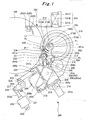
- the arrangement of the supporting plate 217 and the angle of the squeegee supporting member 219 are determined such that, as shown in Fig. 1 , a center P 1 of the rotary screen 201, the center P 2 of turning movement of the squeegee 213 (squeegee supporting member 219), and a point P 3 of contact between the tip of the blade 213A and the screen plate 201A are all located along a straight line (L 1 shown in Fig. 1 ) during printing.
- the eccentric sleeve 221 is swingably supported on a pin 220 fixed to a fourth coupling bracket 204d formed at each axial end of the sub-frame 204 and turnably supported on the supporting plate 217. Moreover, a slotted hole 221a is formed in a flange portion of the eccentric sleeve 221, and a pin 221b fixed to the supporting plate 217 is fitted in this slotted hole 221a.
- This eccentric sleeve 221 is given an eccentric design so that, during printing, the tip of the blade 213A can be moved via the supporting plate 217 along a tangent line L 2 of the impression cylinder 100 at the above-mentioned contact point P 3 , in other words, the position of the supporting plate 217 can be adjusted relative to a center P 4 of turning movement of the eccentric sleeve 221 in parallel with the tangent line L 2 .
- the eccentricity effect of the eccentric sleeve 221 moves the supporting plate 217 in parallel with the tangent line L 2 , which in turn moves the tip of the blade 213A supported on the supporting plate 217 along the tangent line L 2 .
- the axis of the pin 220 i.e. the center P 4 of turning movement of the eccentric sleeve 221
- the above-mentioned contact surface 217a of the supporting plate 217 which comes into contact with the screw 236 is arranged at a position at which the contact surface 217a is flush with the tangent line L 2 .
- the contact surface 217a does not necessarily have to be provided at this position at which it is flush with the tangent line L 2 .
- the contact surface 217a only needs to be a surface which comes into contact with the screw 236 and is parallel with the tangent line L 2 .
- the above-mentioned screw 236 is threadedly engaged with a fifth coupling bracket 204e fixed to the sub-frame 204.
- the tip of the screw 236 protrudes from the fifth coupling bracket 204e toward the contact surface 217a.
- the pressing force of the blade 213A against the impression cylinder 100 during printing is adjusted based on the amount of protrusion of the screw 236.
- the operator may directly turn the screw 236 to adjust the amount of protrusion of the screw 236, or a gear of a motor not shown may be engaged with the screw 236 and the screw 236 may be turned via a remote operation to adjust the amount of protrusion thereof.
- the supporting plate 217, the squeegee supporting member 219, the eccentric sleeve 221, and the screw 236 form squeegee supporting means, and the worm 234 and the worm wheel 235 form an angle adjustment unit.
- the screw 236 and the contact surface 217a form a stopper part.
- the squeegee replacement assisting means includes a slide rail 231 and a hoist 232 turnably supported on this slide rail 231 with a hinge 233 interposed therebetween.
- the slide rail 231 extends in the axial direction of the rotary screen 201 and is supported on the left and right machine frames 101 above the rotary screen 201.
- This slide rail 231 includes a fixed rail 231A, an intermediate rail 231B, and a movable rail 231C.
- the fixed rail 231A is fixed to the left and right machine frames 101.
- the intermediate rail 231B is supported on the fixed rail 231A in such a way as to be slidable in the axial direction of the rotary screen 201.
- the movable rail 231C is supported on the intermediate rail 231B in such a way as to be slidable in the axial direction of the rotary screen 201.
- the intermediate rail 231B is slidably coupled to both the fixed rail 231A and the movable rail 231C, so that the slide rail 231 functions as an extendable guide capable of extension and retraction.
- this slide rail 231 is a guide rail having a similar structure to that of the slide rail disclosed in Patent Literature 2, for example, and configured to extend and retract in the longitudinal direction. Thus, detailed description thereof is omitted here.
- a base end portion of the hoist 232 is supported on one end (the left end in Fig. 2 ) of the movable rail 231C with the hinge 233 interposed therebetween such that the hoist 232 can be turned along the side surface of the corresponding frame 101.
- this hoist 232 is provided at a free end portion thereof with a squeegee bearing portion 232A, a locking plate 232B, a handle 232C, squeegee raising-lowering means not shown, and a grip 232D.
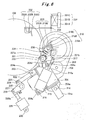
- the squeegee bearing portion 232A is formed in an L-shape so that the squeegee bearing portion 232A at a hoist work position illustrated in Fig. 6 with two-dot chain lines can be fitted to a side surface and the lower surface of the squeegee bar 213B which has a rectangular shape in cross section.
- the locking plate 232B is configured to fix the squeegee bar 213B housed in the squeegee bearing portion 232A by closing an opening portion of the squeegee bearing portion 232A. Note that the locking plate 232B is coupled to the squeegee bearing portion 232A with a screw not shown, and the locking plate 232B can be turned when the fastening of the squeegee bearing portion 232A and the locking plate 232B is loosened by turning the handle 232C fixed to the tip of the screw.
- the squeegee bar 213B can be detached from the squeegee bearing portion 232A or the squeegee bar 213B can be attached to the squeegee bearing portion 232A by turning the locking plate 232B to open the opening portion.
- the squeegee raising-lowering means is means for moving the squeegee bearing portion 232A and the locking plate 232B together in the longitudinal direction of the hoist 232.
- the squeegee raising-lowering means vertically moves the squeegee bar 213B supported on the squeegee bearing portion 232A with the bottom surface of the rectangular portion thereof held substantially horizontally.
- the squeegee raising-lowering means may be one supporting the squeegee bearing portion 232A on the hoist 232 with a feed screw interposed therebetween, and using a manually turned handle or a motor to rotate this feed screw.
- the squeegee raising-lowering means may be an air cylinder coupling the squeegee bearing portion 232A and the hoist 232. Note that the grip 232D is used to move the hoist 232, for example.
- a control unit 300 of the rotary screen printing press receives operation signals from a plate replacement switch 301, a plate mount completion switch 302, the screen-plate left-right position adjustment switch 308, a rotary encoder 303, a print start switch 304, a counter 305, and a print stop switch 306, a squeegee replacement switch 309, a squeegee mount completion switch 310, and a squeegee angle adjustment switch 311, and also receives a detection signal from a timer 307.
- control unit 300 is configured to control drive of the clutch 210, the rotary-screen position adjustment motor 211, the tension cylinder 212, the drive motor 209, the squeegee engagement-disengagement cylinder 215, the screen-plate engagement-disengagement cylinder 228, the squeegee angle adjustment motor 238, and the timer 307.
- control unit 300 receives an operation signal from the print start switch 304, and the rotary encoder 303 detects a print start phase for the first sheet (printing object). In response, the control unit 300 outputs a command to the squeegee engagement-disengagement cylinders 215 to extend their drive rods 215a, and also outputs a command to the screen-plate engagement-disengagement cylinder 228 to retract its drive rod 228a.
- the whole sub-frame 204 is swung via the third link member 227, the second link members 224, and the first link members 222 about the pins 214 in such a direction (counterclockwise in Fig. 1 ) as to approach the impression cylinder 100.
- the supporting plates 217 are swung about the pins 220 in such a direction (counterclockwise in Fig. 1 ) that the blade 213A approaches the inner peripheral surface of the screen plate 201A.
- the rotary screen 201 is positioned from a rotary-screen disengagement position at which the screen plate 201A is separated from the impression cylinder 100, to a rotary-screen engagement position (the position illustrated in Fig. 1 ) at which the screen plate 201A is in contact with the impression cylinder 100.
- the squeegee 213 is positioned from a squeegee disengagement position at which the tip of the blade 213A is near the inner peripheral surface of the screen plate 201A but separated from the inner peripheral surface, to a squeegee engagement position (the position illustrated in Fig.
- the squeegee 213 is positioned by the squeegee supporting members 219 at an initial angle (the angle of the squeegee supporting members 219 at the squeegee engagement position--a preset angle with which a new squeegee 213 can be set at an optimal squeegee angle).
- the contact surfaces 217a of the supporting plates 217 come into contact with the tips of the screws 236 and pushed by the biasing force of the squeegee engagement-disengagement cylinders 215.
- each squeegee angle adjustment motor 238 via a remote operation and turn each squeegee supporting member 219 along the corresponding arc-shaped notched portion.
- the displacement of the tip of the blade 213A in the direction of the tangent line L 2 caused by this step is corrected by turning each eccentric sleeve 221 to move the tip of the blade 213A in the direction of the tangent line L 2 and slide each contact surface 217a, which is in parallel with the tangent line L 2 (or, in this embodiment, formed at such a position as to be flush with the tangent line L 2 ), in the direction of the tangent line L 2 while maintaining the contact with the corresponding screw 236.
- the pressing force of the blade 213A against the screen plate 201A is adjusted by adjusting the amount of protrusion of each screw 236.
- the operator operates the screen-plate left-right position adjustment switch 308.
- the control unit 300 outputs a command to the rotary-screen position adjustment motor 211 to rotate its drive rod 211a in according with the request from the screen-plate left-right position adjustment switch 308.
- the rotary screen 201 is moved together in the axial direction, and the other rotary-screen bracket 203 is moved in the axial direction against the biasing force of the tension cylinder 212 to follow the movement of the one rotary-screen bracket 203 via the rotary screen 201.
- the rotary-screen position adjustment motor 211 is driven in the opposite direction from that in the above case, the one rotary-screen bracket 203 is moved in a direction toward the other rotary-screen bracket 203.
- the rotary screen 201 is moved together in the axial direction, and the other rotary-screen bracket 203 is moved in the axial direction by the biasing force of the tension cylinder 212 to follow the movement of the one rotary-screen bracket 203.
- the rotary screen 201 is put in register in the left-right direction. Note that the left-right registration can be performed while printing is performed and after printing is finished.
- the control unit 300 outputs a command to the squeegee engagement-disengagement cylinders 215 to retract their drive rods 215a, and also outputs a command to the screen-plate engagement-disengagement cylinder 228 to extend its drive rod 228a.
- the supporting plates 217 are swung about the pins 220 in such a direction (clockwise in Fig.
- the whole sub-frame 204 is swung via the third link member 227, the second link members 224, and the first link members 222 about the pins 214 in such a direction (clockwise in Fig. 1 ) as to move away from the impression cylinder 100, thereby positioning the rotary screen 201 from the rotary-screen engagement position to the rotary-screen disengagement position via the rotary-screen brackets 203 and the supporting plates 217.
- the rotary screen printing press is now in a print finished state.
- the operator operates the squeegee replacement switch 309 in the above-mentioned print finished state (a state in which the rotary screen unit 200 is positioned at the rotary-screen disengagement position and the squeegee disengagement position).
- the control unit 300 outputs a command to the squeegee engagement-disengagement cylinders 215 to retract their drive rods 215a, and also outputs a command to the squeegee angle adjustment motors 238 to set their squeegee supporting members 219 at the replacement angle.
- the supporting plates 217 are swung about the pins 220 in such a direction (clockwise in Fig.
- the squeegee 213 is positioned from the squeegee disengagement position to a squeegee replacement position (position illustrated in Fig. 6 with two-dot chain lines) to which the squeegee 213 is retreated toward the axis of the rotary screen 201, and also the squeegee 213 is positioned by the squeegee supporting members 219 from the initial angle to the replacement angle.
- the handles 219C of the squeegee supporting members 219 are turned to loosen the screws of the pins 219E and thereby release the locking plates 219B from the state of being sandwiched between the flat portions of the squeegee supporting portions 219A and the lower end surfaces of the handles 219C.
- the locking plates 219B are turned to open the upper openings of the rectangular grooves in the left and right squeegee supporting members 219.
- the hoist 232 is positioned from a hoist retreat position (a position at which the hoist 232 is disposed in such a way as not to overlap the opening portion of the rotary screen 201 in the radial direction; e.g. a position illustrated in Fig.
- the hoist work position (more specifically, a hoist nearby position at which the slide rail 231 is retracted and the hoist 232 is set near the frame 101 in the axial direction, and at which the hoist 232 is disposed with its squeegee bearing portion 232A substantially overlapping, in the radial direction, the squeegee supporting members 219 positioned at the squeegee replacement position) .
- the squeegee bearing portion 232A is positioned lower than the squeegee 213 supported on the squeegee holding members 219 (squeegee mount position).
- the squeegee bearing portion 232A is, for example, raised vertically with the squeegee raising-lowering means from the squeegee mount position (the state in which the squeegee bearing portion 232A is positioned lower than the squeegee 213 supported on the squeegee supporting members 219) to a squeegee dismount position (a state in which the squeegee bearing portion 232A is positioned higher than the squeegee 213 supported on the squeegee supporting members 219).
- the squeegee bar 213B is detached from the rectangular grooves in the squeegee holding members 219.
- the squeegee bar 213B is transferred from the left and right squeegee supporting members 219 onto the squeegee bearing portion 232A.
- the raising of the squeegee 213 is stopped, and the hoist 232 is moved from the hoist nearby position to a hoist separated position (a position at which the hoist 232 is separated from the frame 101 in the axial direction of the rotary screen 201 as a result of extending the slide rail 231).
- a hoist separated position a position at which the hoist 232 is separated from the frame 101 in the axial direction of the rotary screen 201 as a result of extending the slide rail 231).
- the control unit 300 outputs a command to the clutch 210 to release its connection to the rotary shaft 226, and also outputs a command to the tension cylinder 212 to retract its drive rod.
- the connection between the clutch 210 and the rotary shaft 206 is released, and the pressing force of the tension cylinder 212 against the corresponding rotary-screen bracket 203 is released.
- the end rings 201B are attached to the opposite ends of a new screen plate 201A.
- the drive-side end ring 201B on the new screen plate 201A is attached to the drive-side bearing member 202.
- the work-side bearing member 202 is moved axially inward, the new screen plate 201A is turned for phase alignment with the work-side end ring 201B on the new screen plate 201A, and the end ring 201B is attached to the bearing member 202.
- the method of attaching the end rings 201 (rotary screen 201) to the bearing members 202 is as described above, and detailed description thereof is omitted here.
- the hoist 232 is moved to the hoist nearby position.
- the slide rail 231 retracts to guide the hoist 232.
- the squeegee 213 is lowered with the squeegee raising-lowering means.
- the squeegee bar 213B is fitted into the rectangular grooves in the left and right squeegee supporting members 219, the lowering of the squeegee 213 with the squeegee raising-lowering means is temporarily stopped.
- the handle 232C of the hoist 232 is then operated to release the squeegee bar 213 from the state of being sandwiched by the locking plate 232B, and the opening portion of the squeegee bearing portion 232A is opened.
- the lowering of the squeegee 213 with the squeegee raising-lowering means is resumed.
- the squeegee bearing portion 232A is lowered, and the squeegee bar 213B is detached from the squeegee bearing portion 232A.
- the squeegee bar 213B is transferred from the squeegee bearing portion 232A onto the left and right squeegee supporting members 219.
- the locking plates 219B of the left and right squeegee supporting members 219 are turned to such a position that the bottom surfaces of the notches 219Ba of the locking plates 219B come into contact with the pins 219E.
- the opening portions of the rectangular grooves are closed by the locking plates 219B.
- the handles 219C are then turned to fix the squeegee bar 213B inside the rectangular grooves in the left and right squeegee supporting members 219.
- the hoist 232 is positioned to the hoist retreat position. Thereafter, when the squeegee mount completion switch 310 is operated, the control unit 300 outputs a command to the squeegee engagement-disengagement cylinders 215 to extend their drive rods 215a, and also outputs a command to the squeegee angle adjustment motors 238 to set their squeegee supporting members 219 at the initial angle. As a result, the supporting plates 217 are swung about the pins 220 in such a direction (counterclockwise in Fig.
- the squeegee 213 is positioned at the squeegee disengagement position, and also the squeegee 213 is positioned at the initial angle by the squeegee supporting members 219.
- the control unit 300 When the plate mount completion switch 302 is operated, the control unit 300 outputs a command to the tension cylinder 212 to extend its drive rod 212a, and also outputs a command to the drive motor 209 to turn on and a command to the timer 307 to start timing.
- the rotary screen 201 is set to a tensioned state, and the drive of the drive motor 209 is transmitted to one end of the rotary screen 201 through the gear 209a of the drive motor 209, the gear 205a of the rotary shaft 205, one of the intermediate gears 208, the gear 202a of the one bearing members 202, and the one bearing member 202.
- the gear 206a of the rotary shaft 206 is rotated via the other bearing member 202 provided at the other end of the rotary screen 201, the gear 202a of the other bearing member 202, and the other intermediate gear 208.
- the rotary shaft 205 is rotated, the rotary shaft 206 is rotated as well.
- the gear 206a of the rotary shaft 206 can be rotated freely relative to the rotary shaft 206.
- the control unit 300 outputs a command to the clutch 210 to connect to the rotary shaft 206.
- the gear 206a is drivably connected so that the gear 206a can rotate together with the rotary shaft 206.
- the drive of the drive motor 209 is transmitted also to the other end of the rotary screen 201 through the gear 209a of the drive motor 209, the gear 205a of the rotary shaft 205, the rotary shaft 205, the coupling member 207, the rotary shaft 206, the clutch 210, the gear 206a of the rotary shaft 206, the other intermediate gear 208, the gear 202a of the other bearing member 202, and the other bearing member 202.
- the opposite ends of the rotary screen 201 are now rotationally driven by the drive motor 209.
- the control unit 300 outputs a command to the drive motor 209 to stop. By this step, the replacement of the screen plate 201A is completed.
- the operator For replacement of the squeegee 213, the operator operates the squeegee replacement switch 309.
- the control unit 300 outputs a command to the squeegee engagement-disengagement cylinders 215 to retract their drive rods 215a, and also outputs a command to the squeegee angle adjustment motors 238 to set their squeegee supporting members 219 at the replacement angle.
- the supporting plates 217 are swung about the pins 220 in such a direction (clockwise in Fig.
- the squeegee 213 is positioned from the squeegee disengagement position to the squeegee replacement position to which the squeegee 213 is retreated toward the axis of the rotary screen 201, and also the squeegee 213 is positioned at the replacement angle by the squeegee supporting members 219.
- the handles 219C of the squeegee supporting members 219 are turned to loosen the screws of the pins 219E and thereby release the locking plates 219B from the state of being sandwiched between the flat portions of the squeegee supporting portions 219A and the lower end surfaces of the handles 219C.
- the locking plates 219B are turned to open the upper openings of the rectangular grooves in the left and right squeegee supporting members 219.
- the hoist 232 is positioned from the hoist retreat position to the hoist work position.
- the squeegee bearing portion 232A is positioned lower than the squeegee 213 supported on the squeegee holding members 219 (mount position).
- the squeegee bearing portion 232A is, for example, raised vertically with the squeegee raising-lowering means from the squeegee mount position to the squeegee dismount position.
- the squeegee bar 213B is fitted into the squeegee bearing portion 232A, the raising of the squeegee bearing portion 232A (squeegee 213) with the squeegee raising-lowering means is temporarily stopped.
- the locking plate 232B is turned to close the opening portion, and the handle 232C is turned to fix the squeegee bar 213B to the squeegee bearing portion 232A in the sandwiching manner.
- the raising of the squeegee bearing portion 232A with the squeegee raising-lowering means is resumed.
- the squeegee bar 213B is detached from the rectangular grooves in the squeegee holding members 219.
- the squeegee bar 213B is transferred from the left and right squeegee supporting members 219 onto the squeegee bearing portion 232A.
- the raising of the squeegee 213 is stopped, and the hoist 232 is moved from the hoist nearby position to the hoist separated position.
- the slide rail 231 extends to guide the hoist 232.
- the handle 232C of the hoist 232 is turned.
- the screw of the pin not shown operates in such a way as to release the squeegee bar 213B from the state of being sandwiched between the locking plate 232B and a flat portion of the squeegee bearing portion 232A.
- the locking plate 232B is turned to open the upper opening of the rectangular groove in the squeegee bearing portion 232A, and the used squeegee 213 is removed.
- the squeegee bar 213B of the new squeegee 213 is fitted into the rectangular groove in the squeegee bearing portion 232A, and the locking plate 232B is turned to close the opening portion.
- the handle 232C is then turned.
- the screw of the pin not shown operates in such a way as to sandwich and fix the squeegee bar 213B between the locking plate 232B and the flat portion of the squeegee bearing portion 232A, so that the squeegee 213 is supported at one end.
- the squeegee 213 is raised with the squeegee raising-lowering means via the squeegee bearing portion 232A and the locking plate 232B, and the hoist 232 is moved to the hoist nearby position.
- the slide rail 231 retracts to guide the hoist 232.
- the squeegee 213 is lowered with the squeegee raising-lowering means.
- the squeegee bar 213B is fitted into the rectangular grooves in the left and right squeegee supporting members 219, the lowering of the squeegee 213 with the squeegee raising-lowering means is temporarily stopped.
- the locking plate 232B is then operated to open the opening portion, and the lowering of the squeegee 213 with the squeegee raising-lowering means is resumed.
- the squeegee bearing portion 232A is lowered, and the squeegee bar 213B is detached from the squeegee bearing portion 232A.
- the squeegee bar 213B is transferred from the squeegee bearing portion 232A onto the left and right squeegee supporting members 219.
- the locking plates 219B of the left and right squeegee supporting members 219 are turned to such a position that the bottom surfaces of the notches 219Ba of the locking plates 219B come into contact with the pins 219E.
- the opening portions of the rectangular grooves are closed by the locking plates 219B.
- the handles 219C are then turned.
- the screws of the pins not shown operate in such a way as to fix the squeegee bar 213B inside the rectangular grooves in the left and right squeegee supporting members 219.
- the hoist 232 is positioned to the hoist retreat position.
- the control unit 300 outputs a command to the squeegee engagement-disengagement cylinders 215 to extend their drive rods 215a, and also outputs a command to the squeegee angle adjustment motors 238 to set their squeegee supporting members 219 at the initial angle.
- the supporting plates 217 are swung about the pins 220 in such a direction (counterclockwise in Fig. 1 ) that the blade 213A approaches the inner peripheral surface of the screen plate 201A, and also the squeegee supporting members 219 are turned along the arc-shaped notched portions of the supporting plates 217.
- the squeegee 213 is positioned from the squeegee replacement position to which the squeegee 213 has been retreated toward the axis of the rotary screen 201, to the squeegee disengagement position, and also the squeegee 213 is positioned at the initial angle by the squeegee supporting members 219. By this step, the replacement of the squeegee 213 is completed.
- the rotary screen printing press according to this embodiment described above brings about the following advantageous effects.
- the squeegee supporting members 219, the squeegee angle adjustment motors 238, and the eccentric sleeves 221 are supported on the supporting plates 217, and the eccentric sleeves 221 are given an eccentric design so that the tip of the blade 213A can be moved along the tangent line L 2 of the impression cylinder 100 at the point P 3 of contact between the tip of the blade 213A and the screen plate 201A.
- the squeegee angle is adjusted by operating the squeegee angle adjustment switch 311 to turn the squeegee supporting members 219 with the squeegee angle adjustment motors 238, this angle adjustment displaces the tip of the blade 213A from the contact point P 3 .
- the displacement can be corrected by turning the eccentric sleeves 221 to move the supporting plates 217 in parallel with the tangent line L 2 .
- the contact surfaces 217a which come into contact with the screws 236 of the supporting plates 217 are arranged at such a position as to be parallel with (in this embodiment, to be flush with) the tangent line L 2 .
- the contact surfaces 217a and the screws 236 can make the supporting plates 217 move in parallel with the tangent line L 2 in cooperation with the eccentric sleeves 221.
- the squeegee angle is adjusted by turning the squeegee supporting members 219 with the worms 234.
- the rotary screen printing press according to this embodiment is configured such that the above-mentioned three points P 1 , P 2 , P 3 are all located along a straight line.
- the squeegee angle adjustment motors 238 are provided so that the squeegee supporting portions 219A can be adjusted automatically to the replacement angle when the squeegee 213 is positioned to the hoist work position.
- the rectangular grooves in the squeegee supporting portions 219A are oriented always at the replacement angle suitable for replacement, when the squeegee bar 213B is transferred from the squeegee supporting portions 219A onto the squeegee bearing portion 232A or when the squeegee bar 213B is transferred from the squeegee bearing portion 232A onto the squeegee supporting portions 219A for replacement of the squeegee 213 or the like.
- the transferring work can be done smoothly. Accordingly, the burden on the operator is reduced.
- the left and right (axial) positions at which the supporting plates 217 support the squeegee 213 can be closer to each other. In this way, it is possible to minimize the length of the squeegee 213 and therefore reduce the weight of the squeegee 213. Accordingly, the burden on the operator can be reduced significantly.
- the squeegee 213 and the rotary screen 201 can be moved at the same time to the rotary screen disengagement position, for example, when printing starts or when printing ends.
- the time taken to move the rotary screen 201 and the squeegee 213 can be shortened as compared to conventional cases. Accordingly, the efficiency during printing can be improved.
- means for engaging and disengaging the rotary screen 201 to and from the impression cylinder 100 and means for engaging and disengaging the squeegee 213 to and from the rotary screen 201 are configured to be driven independently of each other.
- the squeegee 213 when printing ends, it is necessary to firstly move the squeegee 213 toward the axis of the rotary screen 201 to protect the screen plate 201A from the blade 201A, and then separate the rotary screen 201 from the impression cylinder 100, and therefore the rotary screen 201 is not separated immediately. Moreover, since the rotary screen 201 needs to be separated from the impression cylinder 100 immediately after the end of printing, the squeegee 213 is moved toward the axis of the rotary screen 201 in the middle of the printing of the last sheet so that the rotary screen 201 can be separated from the impression cylinder 100 immediately after the end of printing. This causes defective printing of the last sheet.
- the supporting plates 217 are supported on the sub-frame 204, and therefore the squeegee 213 and the rotary screen 201 can be moved at the same time to the rotary screen disengagement position immediately after the last sheet is printed.
- the rotary screen printing press according to this embodiment has the advantage that printing can be performed without wasting the last sheet.
- the axially opposite ends of the rotary screen 201 are rotationally driven.
- the positions of the bearing members 202 relative to the rotary-screen brackets 203 in the circumferential direction are fixed.
- the screen plate 201A will be twisted across the left and right sides (the two sides in the axial direction) when the left and right end rings 201B are attached to their bearing members 202.
- the rotary-screen rotationally driving means includes the clutch 210.
- the opposite ends of the rotary screen 201 can be attached to the bearing members 202 firstly with the clutch 210 and the rotary shaft 206 disconnected from each other.
- the screen plate 201A can be attached to the bearing members 202 without being twisted, thereby preventing misregistration on the drive side and the work side of the rotary screen 201. Accordingly, the print quality can be improved.
- the clutch 210 is connected after one side of the rotary screen 201 is driven for a given period of time by the drive motor 209, the states of the gears on the left and right sides (axially opposite sides) of the rotary screen 201 (the phases of the gear 202a of the one bearing member 202, the one intermediate gear 208, and the gear 205a of the rotary shaft 205, and the phases of the gear 202a of the other bearing member 202, the other intermediate gear 208, and the gear 206a of the rotary shaft 206) coincide with each other. Accordingly, misregistration on the left and right sides due to backlash can also be prevented.
- the hoist 232 is provided which is supported and moved by the slide rail 231 between the hoist nearby position near the frame 101 and the hoist separated position separated from the frame 101. Also, the axis of swinging movement of the hoist 232 is in parallel with the axial direction of the rotary screen 201. In this way, the hoist 232 can be swung along the side surface of the frame 101, and does not greatlyprotrude from the side surface of the frame 101 even when positioned at the hoist retreat position. Thus, the hoist 232 does not obstruct the operator.
- the hoist 232 does not obstruct visual check on the state of the ink on the rotary screen 201 through the opening at the end of the rotary screen 201 or access to the inside of the rotary screen 201. Accordingly, check, adjustment, and maintenance work can be performed easily.
- the squeegee 213 is passed through the inside of the rotary screen 201.
- the squeegee 213 does not contact the end rings 201B.
- the squeegee 213 does not contact any of the squeegee supporting members 219 (worm wheels 235) positioned at the replacement position. Accordingly, the squeegee 213, the end rings 201B, and the squeegee supporting members 219 do not get damaged.
- the slide rail 231 capable of supporting the hoist 232 at one end, neither the hoist 232 nor the slide rail 231 hardly protrudes to the outer side of the frame 101 when the hoist 232 is positioned at the hoist nearby position. Accordingly, the hoist 232 and the slide rail 231 do not obstruct work. Further, with the hoist 232 and the slide rail 231 having the above-described structure, replacement work of the squeegee can be done by a single operator.
- motors may be used instead of the cylinders, namely the squeegee engagement-disengagement cylinder 215 provided to move the squeegee 213 to the engagement and disengagement positions and the hoist retreat position, and the screen-plate engagement-disengagement cylinder 228 provided to move the rotary screen 201 and the squeegee 213 between the print position and the hoist retreat position.
- the present invention is preferably applicable to a rotary screen printing press which performs screen printing by using a cylindrical screen plate.
Landscapes
- Engineering & Computer Science (AREA)
- Mechanical Engineering (AREA)
- Screen Printers (AREA)
Abstract
Description
- The present invention relates to a rotary screen printing press which performs screen printing by using a cylindrical screen plate.
- Rotary screen printing presses utilizing a rotary screen unit have heretofore been known as high-speed printing apparatuses for printing objects made from a wide range of materials such as cloth and paper. The rotary screen printing presses employ a printing method involving pushing ink with a squeegee through through-holes formed in the plate surface of a screen plate formed in a cylindrical shape to transfer the forced ink onto a printing object.
- In general, in such a rotary screen printing press, the squeegee includes a squeegee body (blade) configured to push ink, and a support (squeegee bar) supporting the blade. To mount the squeegee on the rotary screen printing press, the squeegee is positioned inside a rotary screen, and opposite end portions of the squeegee bar are fixed to squeegee supporting means. Note that the rotary screen refers to a screen plate formed in a cylindrical shape and having end rings attached to the opposite ends thereof as supporting members.
- There has been known a structure in which a conventional rotary screen printing press as described above includes screen-plate supporting means for supporting a rotary screen in such a way that the rotary screen can be engaged with and disengaged from an impression cylinder, and squeegee supporting means for supporting the opposite ends of a squeegee bar in such a way that a blade can be engaged with and disengaged from the inner peripheral surface of the rotary screen (see Patent Literature 1, for example).
- Moreover, there has been known a technique for a screen printing press using a flat screen plate to perform screen printing, in which the angle of the squeegee is adjusted based on printing conditions such as the viscosity of the ink, the diameter of the print pattern holes, and the pitch of the holes (see Patent Literature 2, for example).
- {Patent Literature 1}Japanese Patent Application Publication No.
2008-201119 Hei 7-241977 - Like Patent Literature 2 mentioned above, rotary screen printing presses are also required to adjust the angles of their squeegees. However, in a rotary screen printing press, a printing object comes into contact with the peripheral surface of the rotary screen, or a cylindrical body. Thus, a problem may occur in that the adjustment of the squeegee angle displaces the tip of the squeegee from the contact position and deteriorates the print quality.
- In view of the above, an object of the present invention is to provide a rotary screen printing press capable of squeegee angle adjustment and capable of high quality printing.
- A rotary screen printing press according to the present invention for solving the above-mentioned problem includes: a screen plate formed in a cylindrical shape; a squeegee; squeegee supporting means for supporting the squeegee; and an angle adjustment unit configured to adjust an angle of the squeegee, in which the squeegee supporting means includes an arm swingably supported and supporting the angle adjustment unit, a squeegee position adjustment unit configured to adjust a position of a center of swinging movement of the arm, and a stopper part configured to limit a direction of the movement of the arm, and the squeegee position adjustment unit and the stopper part cooperate with each other to move a tip of the squeegee along a tangent line of an impression cylinder at a position at which the screen plate and the squeegee contact each other.
- Moreover, the stopper part includes a contact surface formed as a flat surface, and a contact member configured to contact the contact surface, and the center of the swinging movement of the arm and the contact surface are arranged on the tangent line of the impression cylinder at the position at which the screen plate and the squeegee contact each other.
- According to the rotary screen printing press according to the present invention, it is possible to adjust the angle of the squeegee in accordance with printing conditions while maintaining the print quality. Thus, high quality printing can be performed constantly.
-
- {
Fig. 1}Fig. 1 is an explanatory view showing a rotary screen printing press according to an embodiment of the present invention. - {
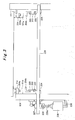
Fig. 2}Fig. 2 is a developed plan view ofFig. 1 . - {
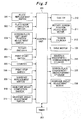
Fig. 3} Fig. 3 is an explanatory view showing the relationship between frames and a sub-frame in the rotary screen printing press according to the embodiment of the present invention. - {
Fig. 4}Fig. 4 is an explanatory view showing a squeegee supporting member of the rotary screen printing press according to the embodiment of the present invention. - {
Fig. 5}Fig. 5 is a block diagram showing the configuration of the rotary screen printing press according to the embodiment of the present invention. - {
Fig. 6}Fig. 6 is an explanatory view describing movement of a squeegee and movement of a hoist in the rotary screen printing press according to the embodiment of the present invention. - Hereinbelow, a rotary screen printing press according to an embodiment of the present invention will be described in detail with reference to the drawings. Here, it is needless to say that the rotary screen printing press according to this embodiment is not limited to the structure to be described below, and various changes can be made without departing from the gist of the present invention.
- As shown in
Figs. 1 and2 , the rotary screen printing press according to this embodiment includes animpression cylinder 100 and arotary screen unit 200. - The
impression cylinder 100 is rotatably supported between left and right machine frames 101, 101. Though not illustrated, a notched portion is formed in the outer peripheral surface of theimpression cylinder 100 along the axial direction of theimpression cylinder 100. There are multiple notched portions (e.g. two in this embodiment) formed at an equal interval in the circumferential direction of theimpression cylinder 100. Moreover, inside these notched portions, theimpression cylinder 100 includes gripper units (holding portions) not shown configured to grip and hold a tip of a sheet which is a printing object. - On the other hand, the
rotary screen unit 200 includes arotary screen 201 and asqueegee 213. - As shown in
Fig. 2 , therotary screen 201 includes ascreen plate 201A and annular end rings 201B, 201B fixed to opposite ends (left and right ends inFig. 2 ) of thescreen plate 201A, respectively. Thescreen plate 201A is a cylindrical body being a cylindrical thin plate material through which fine holes are etched in a given pattern. Eachend ring 201B is a member for reinforcing thescreen plate 201A. - Here, a protruding portion not shown (hereinafter, "end-ring protruding portion"), multiple (two in this embodiment) notched portions not shown (hereinafter, "end-ring notched portions), and a pin groove not shown are formed on and in each
end ring 201B. The end-ring protruding portion is a flange protruding radially outward from the outer peripheral surface of an end portion on the opposite side from thescreen plate 201A in the axial direction of theend ring 201B. The multiple end-ring notched portions are provided in this end-ring protruding portion at an equal interval in the circumferential direction. The pin groove is provided in the end-ring protruding portion between the adjacent end-ring notched portions and formed by cutting the outer peripheral surface of the end-ring protruding portion in a U-shape toward the axis. These end rings 201B are supported on bearingmembers 202. - Meanwhile, multiple (two in this embodiment) protruding portions not shown (hereinafter, "bearing-member protruding portions") are formed on each bearing
member 202, and a pin not shown is provided thereon as well. The bearing-member protruding portions protrude radially inward from the inner peripheral surface of the bearingmember 202 on theend ring 201B side in the axial direction thereof and provided at an equal interval in the circumferential direction (the same interval as that of the end-ring notched portions). Note that the shape of the bearing-member protruding portions is designed such that the bearing-member protruding portions can pass through the end-ring notched portions in the radial direction. Moreover, the pin is fixed to one of the bearing-member protruding portions in such a way as to be engaged with the pin groove in theend ring 201B when theend ring 201B is attached to the bearingmember 202. - To attach each
end ring 201B to the corresponding bearingmember 202, therotary screen 201 is moved in the axial direction with the end-ring notched portions of theend ring 201B and the bearing-member protruding portions of the bearingmember 202 aligned with each other in the circumferential direction, to thereby insert theend ring 201B into the hollow portion of the bearingmember 202 to such an extent that the bearing-member protruding portions and the pin are positioned inside the end-ring protruding portion in the axial direction. Thereafter, therotary screen 201 is turned relative to the bearingmember 202 to align the pin groove of theend ring 201B and the pin of the bearingmember 202 with each other in the circumferential direction. Then, therotary screen 201 is moved in the axial direction relative to the bearingmember 202 to bring the pin of the bearingmember 202 into engagement with the pin groove of theend ring 201B. As a result, the end-ring protruding portion and the bearing-member protruding portions overlap each other in the circumferential direction. Accordingly, therotary screen 201 can be prevented from falling from the bearingmember 202. In addition, by the engagement between the pin groove of theend ring 201B and the pin of the bearingmember 202, therotary screen 201 can be supported on the bearingmember 202 with circumferential movement of therotary screen 201 relative to the bearingmember 202 restricted in a state where the phase of therotary screen 201 accurately coincides with that of the bearing member 202 (in register in the top-bottom direction). - Morever, to detach each
end ring 201B from the corresponding bearingmember 202, therotary screen 201 is moved outward in the axial direction (toward the bearing member 202) to release the engagement between the pin groove of theend ring 201B and the pin of the bearingmember 202, and position the bearing-member protruding portions and the pin of the bearingmember 202 inside the end-ring protruding portion in the axial direction. Then, since the end-ring protruding portion and the bearing-member protruding portions overlap each other in the circumferential direction, therotary screen 201 is turned relative to the bearingmember 202, and therotary screen 201 is moved in the axial direction with the end-ring notched portions and the bearing-member protruding portions aligned with each other in the circumferential direction. As a result, theend ring 201B (rotary screen 201) is removed from the bearingmember 202. - The
rotary screen 201 according to this embodiment having the above-described structure includes rotary-screen rotationally driving means, rotary-screen left-right registration adjusting means, and rotary-screen engaging-disengaging means. - Hereinbelow, the rotary-screen rotationally driving means and the rotary-screen left-right registration adjusting means in this embodiment will be described with reference to
Figs. 1 to 3 . - In this embodiment, the rotary-screen rotationally driving means for rotationally driving the
rotary screen 201 at the opposite ends thereof includes adrive motor 209,gears rotary shafts coupling member 207, and a clutch 210, all of which are shown inFigs. 1 and2 . Moreover, the rotary-screen left-right registration adjusting means includes two rotary-screen brackets 203, therotary shafts position adjustment motor 211, and atension cylinder 212. The rotary-screen brackets 203 are provided to asub-frame 204 to which thedrive motor 209 is fixed and which is swingably supported on the machine frames 101, 101 of theimpression cylinder 100. Moreover, the rotary-screen brackets 203 are supported on thesub-frame 204 in such a way as to be slidable in the axial direction of therotary screen 201, and support the axially opposite ends of therotary screen 201 in a rotatable manner. Therotary shafts screen brackets 203. The rotary-screenposition adjustment motor 211 and thetension cylinder 212 are arranged inside thesub-frame 204. - To describe this structure more specifically with reference to
Fig. 2 , thesub-frame 204 is formed in a box shape, and its longitudinal direction extends in the axial direction of therotary screen 201. Thissub-frame 204 is disposed in the vicinity of therotary screen 201 and theimpression cylinder 100. - Note that as shown in
Fig. 3 ,first coupling brackets 204a are formed at base end portions of thesub-frame 204 on the axially opposite sides thereof, and thefirst coupling brackets 204a are coupled tocoupling brackets 101a provided to the machine frames 101 supporting theimpression cylinder 100, thefirst coupling brackets 204a being swingably coupled to thecoupling brackets 101a withpins 214 interposed therebetween. - Moreover, as shown in
Fig. 2 , a tip portion of each rotary-screen bracket 203 forms a rotary-screen supporting portion 203a, while a base end portion forms a rotary-shaft supporting portion 203b. The rotary-screen supporting portion 203a has a through-hole, and the bearingmember 202 described above is rotatably supported in this through-hole. On the other hand, the rotary-shaft supporting portion 203b is formed in a frame shape, and a through-hole is formed in a surface thereof expanding perpendicularly to the axial direction. Moreover, therotary shafts shaft supporting portions 203b of the rotary-screen brackets 203 on both sides in the axial direction, respectively. Further, each rotary-shaft supporting portion 203b is slidably supported on a rail not shown extending in the axial direction of therotary screen 201 inside thesub-frame 204. - Here, the
rotary shaft 205 and therotary shaft 206 are coupled to each other by atubular coupling member 207 in such a way as to capable of rotating together and moving relative to each other in the axial direction. Specifically, one end of therotary shaft 205 is inserted in and fixed to one end side of thecoupling member 207. On the other hand, splines are formed on the inner peripheral surface of the other end side of thecoupling member 207 and on the outer peripheral surface of one end side of therotary shaft 206. The one end side of therotary shaft 206 is inserted in the other end side of thecoupling member 207 such that the splines formed on thecoupling member 207 and the splines formed on the one end side of therotary shaft 206 mesh with each other. - Moreover, the
gear 205a is formed on the other end of therotary shaft 205, and thegear 202a is formed on the outer peripheral surface of one of the bearing members 202 (the right one inFig. 2 ). Moreover, thegear 205a of therotary shaft 205 and thegear 202a of the onebearing member 202 are in mesh with each other with theintermediate gear 208 interposed therebetween, and thegear 205a of therotary shaft 205 and thegear 209a of thedrive motor 209 are also in mesh with each other (seeFig. 1 ). - Further, the
gear 206a is formed on the other end of therotary shaft 206 with the clutch 210 interposed therebetween, and anothergear 202a is formed on the outer peripheral surface of the other bearing member 202 (the left one inFig. 2 ). Also, thegear 206a of therotary shaft 206 and thegear 202a of the other bearingmember 202 are in mesh with each other with anotherintermediate gear 208 interposed therebetween. - Furthermore, the rotary-
shaft supporting portion 203b of one of the rotary-screen brackets 203 (the right one inFig. 2 ) is configured to be movable in the axial direction with the assistance of the rotary-screenposition adjustment motor 211. Specifically, ascrew 211b is formed at the tip of adrive rod 211a configured to rotate with the drive of the rotary-screenposition adjustment motor 211. On the other hand, ablock 239 in which a female screw threadedly engageable with thescrew 211b is formed is fixed to the one rotary-shaft supporting portion 203b, and thescrew 211b is threadedly attached to thisblock 239. Thus, the one rotary-shaft supporting portion 203b (rotary-screen bracket 203) moves in the axial direction along the above-mentioned rail not shown extending inside thesub-frame 204 as thescrew 211b rotates with the drive of the rotary-screenposition adjustment motor 211. Note that the rotary-screenposition adjustment motor 211 adjusts the left-right (axial) position of thescreen plate 201A by being driven in response to operation of a screen-plate left-right position adjustment switch 308 (seeFig. 5 ). The screen-plate left-rightposition adjustment switch 308 may be of a type which includes a left button and a right button and adjusts the left-right (axial) position of thescreen plate 201A according to operation of these buttons, a type which involves inputting a moving direction and a moving amount, or the like, for example. - In addition, the tip of the
tension cylinder 212 is in contact with a surface of the rotary-shaft supporting portion 203b of the other rotary-screen bracket 203 (the left one inFig. 2 ), the surface expanding perpendicularly to the axial direction. Thetension cylinder 212 is provided to apply force to and tension therotary screen 201 in such a way as to stretch therotary screen 201 in the axial direction thereof, and configured to push the other rotary-screen bracket 203 in the opposite direction from the one rotary-screen bracket 203. Thus, therotary screen 201 is constantly subjected to tension in the axial direction thereof. - Next, the rotary-screen engaging-disengaging means in this embodiment will be described with reference to
Figs. 1 and3 . - As shown in
Fig. 1 , in this embodiment, the rotary-screen engaging-disengaging means includes the above-describedsub-frame 204 and rotary-screen brackets 203, as well as a screen-plate engagement-disengagement cylinder 228 coupled to thesub-frame 204 with first, second, andthird link members - To describe this structure more specifically with reference to
Figs. 1 and3 , thefirst link members 222 are coupled tosecond coupling brackets 204b formed at the axially opposite ends of thesub-frame 204, thefirst link members 222 being swingably coupled to thesecond coupling brackets 204b withpins 223 interposed therebetween. Thefirst link members 222 are swingably coupled also to free end portions of thesecond link members 224 withpins 225 interposed therebetween. Base end portions of thesecond link members 224 are fixed to arotary shaft 226. - Here, the
first link members 222 and thesecond link members 224 are arranged at the inner side of the left and right machine frames 101. Therotary shaft 226 is arranged with its axial direction in parallel with the axial direction of therotary screen 201 and penetrates the machine frames 101 in such a way that at least one end thereof (the left end inFig. 3 ) protrudes to the outer side of thecorresponding machine frame 101. - Moreover, a base end portion of the
third link member 227 is fixed to the one end of therotary shaft 226 at the outer side of themachine frame 101. A free end portion of thethird link member 227 is swingably coupled to adrive rod 228a of the screen-plate engagement-disengagement cylinder 228 with apin 229 interposed therebetween. The body of the screen-plate engagement-disengagement cylinder 228 is swingably coupled to themachine frame 101 with apin 230 interposed therebetween. Moreover, astopper 237 configured to limit swinging movement of thesub-frame 204 toward theimpression cylinder 101 is disposed on and faces a side surface of thethird link member 227. - While the
rotary screen 201 is as described above, thesqueegee 213 includes ablade 213A and asqueegee bar 213B and is inserted in therotary screen 201 as shown inFigs. 1 and2 . Theblade 213A is a member configured to supply ink on the inner side of thescreen plate 201A toward theimpression cylinder 100 through the fine holes in thescreen plate 201A, i.e. a squeegee body. Thesqueegee bar 213B is a support supporting theblade 213A and has a rectangular portion having a rectangular cross-sectional shape. In the rotary screen printing press, the tip of theblade 213A slides on the inner peripheral surface of thescreen plate 201A, so that the ink supplied into thescreen plate 201A is transferred onto the printing surface of a printing object through the fine holes. - The rotary screen printing press in this embodiment with such a structure includes squeegee position adjusting means and squeegee replacement assisting means.
- The squeegee position adjusting means in this embodiment will be described with reference to
Figs. 1 ,2 ,4 , and6 . - As shown in
Figs. 1 and2 , in this embodiment, the squeegee position adjusting means includes, at each side in the axial direction: a squeegee engagement-disengagement cylinder 215 swingably supported on thesub-frame 204; a supportingplate 217 as an arm swingably supported on thesub-frame 204 and the squeegee engagement-disengagement cylinder 215; asqueegee supporting member 219 turnably supported on the supportingplate 217; aneccentric sleeve 221 as a squeegee position adjustment unit also turnably supported on the supportingplate 217; and a squeegeeangle adjustment motor 238 fixed to the supportingplate 217. - The squeegee engagement-
disengagement cylinder 215 is a two-stage cylinder, and a base end portion thereof is swingably supported on athird coupling bracket 204c formed at each axial end of thesub-frame 204. More specifically, thethird coupling bracket 204c has apin 216 fixed thereto, and the base end portion of the squeegee engagement-disengagement cylinder 215 is swingably supported on thispin 216. - The supporting
plate 217 is a plate-shaped body, and a region thereof is notched in an arc shape, so that an arc-shaped notched portion is formed in the region. Thesqueegee supporting member 219 is turnably supported on this arc-shaped notched portion. Moreover, the above-mentioned squeegee engagement-disengagement cylinder 215 is swingably coupled to another region of the supportingplate 217 with apin 218 interposed therebetween. Furthermore, theeccentric sleeve 221 is turnably supported on another region of the supportingplate 217, and acontact surface 217a which comes into contact with ascrew 236 is formed in this another region as well. Thescrew 236 serves as a stopper (contact member) configured to limit turning movement of the supportingplate 217 toward theimpression cylinder 100. - The
squeegee supporting member 219 is a member configured to detachably hold thesqueegee bar 213B, and includes asqueegee supporting portion 219A formed in a substantially semi-circular shape having a curved portion and a flat portion, alocking plate 219B disposed in such a way as to face the flat portion of thesqueegee supporting portion 219A, and ahandle 219C fixed to one end of thelocking plate 219B. - A worm wheel 235 (see
Fig. 4 ) is provided on the curved portion of thesqueegee supporting portion 219A, and aworm 234 configured to mesh with thisworm wheel 235 is supported on the supportingplate 217. The squeegeeangle adjustment motor 238 is coupled to thisworm 234. As the squeegeeangle adjustment motor 238 is driven, theworm 234 is rotated, and thesqueegee supporting member 219 is thereby turned via the worm gear along the arc-shaped notched portion about a center P2 of turning movement. - The squeegee
angle adjustment motor 238 adjusts the angle at which thesqueegee 213 contacts thescreen plate 201A (hereinbelow, referred to as "squeegee angle") during printing via a squeegee angle adjustment switch 311 (seeFig. 5 ) . Moreover, to detach thesqueegee 213 for replacement or the like, the squeegeeangle adjustment motor 238 is automatically driven along with the squeegee engagement-disengagement cylinder 215 to position thesqueegee supporting member 219 at a preset angle suitable for replacement of the squeegee 213 (replacement angle). - Here, the squeegee
angle adjustment switch 311 may be of a type which includes a plus button and a minus button and works according to operation of these buttons, a type which involves inputting a numeral value as an angle, or the like, for example. Moreover, while the example in which the squeegeeangle adjustment motor 238 is used to rotate theworm 234 is described in this embodiment, theworm 234 may be rotated manually to turn thesqueegee supporting member 219 through the worm gear along the arc-shaped notched portion about the center P2 of turning movement. - A rectangular groove having a rectangular cross-sectional shape (rectangular recessed portion) which can be fitted to the
squeegee bar 213B is formed in the center of the flat portion of thesqueegee supporting portion 219A. Moreover, as shown inFig. 4 , a base end portion of thelocking plate 219B is turnably supported on apin 219D fixed to thesqueegee supporting portion 219A. Thus, the lockingplate 219B can be positioned at a fixing position at which thelocking plate 219B covers an opening portion of the rectangular groove as illustrated inFig. 4 with a solid line, and an opening position at which the rectangular groove is opened as illustrated inFig. 4 with a two-dot chain line. Further, apin 219E, to one end of which thehandle 219C is fixed and on the other end of which a screw is formed, is threadedly engaged with thesqueegee supporting portion 219A, and a notch 219Ba engageable with thepin 219E is formed in a free end portion of thelocking plate 219B. According to this structure, by turning thehandle 219C, the screw of thepin 219E operates in such a way that the lockingplate 219B can be sandwiched and fixed between the flat portion of thesqueegee supporting portion 219A and the lower end surface of thehandle 219C or released from this sandwiched state. - Note that in this embodiment, the arrangement of the supporting
plate 217 and the angle of thesqueegee supporting member 219 are determined such that, as shown inFig. 1 , a center P1 of therotary screen 201, the center P2 of turning movement of the squeegee 213 (squeegee supporting member 219), and a point P3 of contact between the tip of theblade 213A and thescreen plate 201A are all located along a straight line (L1 shown inFig. 1 ) during printing. - The
eccentric sleeve 221 is swingably supported on apin 220 fixed to afourth coupling bracket 204d formed at each axial end of thesub-frame 204 and turnably supported on the supportingplate 217. Moreover, a slottedhole 221a is formed in a flange portion of theeccentric sleeve 221, and apin 221b fixed to the supportingplate 217 is fitted in this slottedhole 221a. - This
eccentric sleeve 221 is given an eccentric design so that, during printing, the tip of theblade 213A can be moved via the supportingplate 217 along a tangent line L2 of theimpression cylinder 100 at the above-mentioned contact point P3, in other words, the position of the supportingplate 217 can be adjusted relative to a center P4 of turning movement of theeccentric sleeve 221 in parallel with the tangent line L2. Thus, as theeccentric sleeve 221 is turned, the eccentricity effect of theeccentric sleeve 221 moves the supportingplate 217 in parallel with the tangent line L2, which in turn moves the tip of theblade 213A supported on the supportingplate 217 along the tangent line L2. - Here, in this embodiment, the axis of the
pin 220, i.e. the center P4 of turning movement of theeccentric sleeve 221, is arranged on the tangent line L2, and the above-mentionedcontact surface 217a of the supportingplate 217 which comes into contact with thescrew 236 is arranged at a position at which thecontact surface 217a is flush with the tangent line L2. However, thecontact surface 217a does not necessarily have to be provided at this position at which it is flush with the tangent line L2. Thecontact surface 217a only needs to be a surface which comes into contact with thescrew 236 and is parallel with the tangent line L2. - The above-mentioned
screw 236 is threadedly engaged with afifth coupling bracket 204e fixed to thesub-frame 204. The tip of thescrew 236 protrudes from thefifth coupling bracket 204e toward thecontact surface 217a. The pressing force of theblade 213A against theimpression cylinder 100 during printing is adjusted based on the amount of protrusion of thescrew 236. Here, the operator may directly turn thescrew 236 to adjust the amount of protrusion of thescrew 236, or a gear of a motor not shown may be engaged with thescrew 236 and thescrew 236 may be turned via a remote operation to adjust the amount of protrusion thereof. - In the rotary screen printing press according to this embodiment, the supporting
plate 217, thesqueegee supporting member 219, theeccentric sleeve 221, and thescrew 236 form squeegee supporting means, and theworm 234 and theworm wheel 235 form an angle adjustment unit. Moreover, thescrew 236 and thecontact surface 217a form a stopper part. - Next, the squeegee replacement assisting means according to this embodiment will be described with reference to
Figs. 1 ,2 , and6 . - As shown in
Figs. 1 and2 , the squeegee replacement assisting means according to this embodiment includes aslide rail 231 and a hoist 232 turnably supported on thisslide rail 231 with ahinge 233 interposed therebetween. - The
slide rail 231 extends in the axial direction of therotary screen 201 and is supported on the left and right machine frames 101 above therotary screen 201. Thisslide rail 231 includes a fixedrail 231A, anintermediate rail 231B, and amovable rail 231C. - The fixed
rail 231A is fixed to the left and right machine frames 101. Theintermediate rail 231B is supported on the fixedrail 231A in such a way as to be slidable in the axial direction of therotary screen 201. Themovable rail 231C is supported on theintermediate rail 231B in such a way as to be slidable in the axial direction of therotary screen 201. In other words, theintermediate rail 231B is slidably coupled to both the fixedrail 231A and themovable rail 231C, so that theslide rail 231 functions as an extendable guide capable of extension and retraction. Moreover, the length to which thisslide rail 231 extended by moving theintermediate rail 231B and themovable rail 231C is set to be greater than the axial length of thesqueegee bar 213B. Note that thisslide rail 231 is a guide rail having a similar structure to that of the slide rail disclosed in Patent Literature 2, for example, and configured to extend and retract in the longitudinal direction. Thus, detailed description thereof is omitted here. - Further, a base end portion of the hoist 232 is supported on one end (the left end in
Fig. 2 ) of themovable rail 231C with thehinge 233 interposed therebetween such that the hoist 232 can be turned along the side surface of thecorresponding frame 101. Moreover, this hoist 232 is provided at a free end portion thereof with asqueegee bearing portion 232A, alocking plate 232B, ahandle 232C, squeegee raising-lowering means not shown, and agrip 232D. - The
squeegee bearing portion 232A is formed in an L-shape so that thesqueegee bearing portion 232A at a hoist work position illustrated inFig. 6 with two-dot chain lines can be fitted to a side surface and the lower surface of thesqueegee bar 213B which has a rectangular shape in cross section. - The locking
plate 232B is configured to fix thesqueegee bar 213B housed in thesqueegee bearing portion 232A by closing an opening portion of thesqueegee bearing portion 232A. Note that the lockingplate 232B is coupled to thesqueegee bearing portion 232A with a screw not shown, and thelocking plate 232B can be turned when the fastening of thesqueegee bearing portion 232A and thelocking plate 232B is loosened by turning thehandle 232C fixed to the tip of the screw. Thus, thesqueegee bar 213B can be detached from thesqueegee bearing portion 232A or thesqueegee bar 213B can be attached to thesqueegee bearing portion 232A by turning thelocking plate 232B to open the opening portion. - The squeegee raising-lowering means is means for moving the
squeegee bearing portion 232A and thelocking plate 232B together in the longitudinal direction of the hoist 232. For example, the squeegee raising-lowering means vertically moves thesqueegee bar 213B supported on thesqueegee bearing portion 232A with the bottom surface of the rectangular portion thereof held substantially horizontally. The squeegee raising-lowering means may be one supporting thesqueegee bearing portion 232A on the hoist 232 with a feed screw interposed therebetween, and using a manually turned handle or a motor to rotate this feed screw. Alternatively, the squeegee raising-lowering means may be an air cylinder coupling thesqueegee bearing portion 232A and the hoist 232. Note that thegrip 232D is used to move the hoist 232, for example. - Next, control by the rotary screen printing press according to this embodiment will be described with reference to
Fig. 5 . - As shown in
Fig. 5 , acontrol unit 300 of the rotary screen printing press according to this embodiment receives operation signals from aplate replacement switch 301, a platemount completion switch 302, the screen-plate left-rightposition adjustment switch 308, arotary encoder 303, aprint start switch 304, acounter 305, and aprint stop switch 306, asqueegee replacement switch 309, a squeegeemount completion switch 310, and a squeegeeangle adjustment switch 311, and also receives a detection signal from atimer 307. - Moreover, the
control unit 300 is configured to control drive of the clutch 210, the rotary-screenposition adjustment motor 211, thetension cylinder 212, thedrive motor 209, the squeegee engagement-disengagement cylinder 215, the screen-plate engagement-disengagement cylinder 228, the squeegeeangle adjustment motor 238, and thetimer 307. - First, the flow of control by the
control unit 300 during printing will be described. In a case of performing printing, thecontrol unit 300 receives an operation signal from theprint start switch 304, and therotary encoder 303 detects a print start phase for the first sheet (printing object). In response, thecontrol unit 300 outputs a command to the squeegee engagement-disengagement cylinders 215 to extend theirdrive rods 215a, and also outputs a command to the screen-plate engagement-disengagement cylinder 228 to retract itsdrive rod 228a. As a result, thewhole sub-frame 204 is swung via thethird link member 227, thesecond link members 224, and thefirst link members 222 about thepins 214 in such a direction (counterclockwise inFig. 1 ) as to approach theimpression cylinder 100. Also, the supportingplates 217 are swung about thepins 220 in such a direction (counterclockwise inFig. 1 ) that theblade 213A approaches the inner peripheral surface of thescreen plate 201A. Accordingly, via the rotary-screen brackets 203 and the supportingplates 217, therotary screen 201 is positioned from a rotary-screen disengagement position at which thescreen plate 201A is separated from theimpression cylinder 100, to a rotary-screen engagement position (the position illustrated inFig. 1 ) at which thescreen plate 201A is in contact with theimpression cylinder 100. Also, inside therotary screen 201, thesqueegee 213 is positioned from a squeegee disengagement position at which the tip of theblade 213A is near the inner peripheral surface of thescreen plate 201A but separated from the inner peripheral surface, to a squeegee engagement position (the position illustrated inFig. 6 with solid lines) at which the tip of theblade 213A is in contact with the inner peripheral surface of thescreen plate 201A. Note that thesqueegee 213 is positioned by thesqueegee supporting members 219 at an initial angle (the angle of thesqueegee supporting members 219 at the squeegee engagement position--a preset angle with which anew squeegee 213 can be set at an optimal squeegee angle). In this step, the contact surfaces 217a of the supportingplates 217 come into contact with the tips of thescrews 236 and pushed by the biasing force of the squeegee engagement-disengagement cylinders 215. - Here, for adjustment of the squeegee angle, it is done by operating the squeegee
angle adjustment switch 311 to thereby drive each squeegeeangle adjustment motor 238 via a remote operation and turn eachsqueegee supporting member 219 along the corresponding arc-shaped notched portion. Moreover, the displacement of the tip of theblade 213A in the direction of the tangent line L2 caused by this step is corrected by turning eacheccentric sleeve 221 to move the tip of theblade 213A in the direction of the tangent line L2 and slide eachcontact surface 217a, which is in parallel with the tangent line L2 (or, in this embodiment, formed at such a position as to be flush with the tangent line L2), in the direction of the tangent line L2 while maintaining the contact with thecorresponding screw 236. Meanwhile, as described above, the pressing force of theblade 213A against thescreen plate 201A is adjusted by adjusting the amount of protrusion of eachscrew 236. - Moreover, for registration of the
screen plate 201A in the left-right direction (axial direction), the operator operates the screen-plate left-rightposition adjustment switch 308. When the screen-plate left-rightposition adjustment switch 308 is operated, thecontrol unit 300 outputs a command to the rotary-screenposition adjustment motor 211 to rotate itsdrive rod 211a in according with the request from the screen-plate left-rightposition adjustment switch 308. Here, in a case where the one rotary-screen bracket 203 is moved in a direction away from the other rotary-screen bracket 203, therotary screen 201 is moved together in the axial direction, and the other rotary-screen bracket 203 is moved in the axial direction against the biasing force of thetension cylinder 212 to follow the movement of the one rotary-screen bracket 203 via therotary screen 201. On the other hand, in a case where the rotary-screenposition adjustment motor 211 is driven in the opposite direction from that in the above case, the one rotary-screen bracket 203 is moved in a direction toward the other rotary-screen bracket 203. By this movement of the one rotary-screen bracket 203, therotary screen 201 is moved together in the axial direction, and the other rotary-screen bracket 203 is moved in the axial direction by the biasing force of thetension cylinder 212 to follow the movement of the one rotary-screen bracket 203. As a result, therotary screen 201 is put in register in the left-right direction. Note that the left-right registration can be performed while printing is performed and after printing is finished. - Thereafter, when the
print stop switch 306 is operated or the number of fed sheets counted by thecounter 305 reaches a predetermined number, and therotary encoder 303 detects a last-sheet print completion phase, thecontrol unit 300 outputs a command to the squeegee engagement-disengagement cylinders 215 to retract theirdrive rods 215a, and also outputs a command to the screen-plate engagement-disengagement cylinder 228 to extend itsdrive rod 228a. As a result, the supportingplates 217 are swung about thepins 220 in such a direction (clockwise inFig. 1 ) that theblade 213A moves away from the inner peripheral surface of thescreen plate 201A, thereby moving theblade 213A from the squeegee engagement position to the squeegee disengagement position. Also, thewhole sub-frame 204 is swung via thethird link member 227, thesecond link members 224, and thefirst link members 222 about thepins 214 in such a direction (clockwise inFig. 1 ) as to move away from theimpression cylinder 100, thereby positioning therotary screen 201 from the rotary-screen engagement position to the rotary-screen disengagement position via the rotary-screen brackets 203 and the supportingplates 217. The rotary screen printing press is now in a print finished state. - Thereafter, for plate replacement, first, the operator operates the
squeegee replacement switch 309 in the above-mentioned print finished state (a state in which therotary screen unit 200 is positioned at the rotary-screen disengagement position and the squeegee disengagement position). In response, thecontrol unit 300 outputs a command to the squeegee engagement-disengagement cylinders 215 to retract theirdrive rods 215a, and also outputs a command to the squeegeeangle adjustment motors 238 to set theirsqueegee supporting members 219 at the replacement angle. As a result, the supportingplates 217 are swung about thepins 220 in such a direction (clockwise inFig. 1 ) that theblade 213A moves away from the inner peripheral surface of thescreen plate 201A, and also thesqueegee supporting members 219 are turned along the arc-shaped notched portions of the supportingplates 217. Accordingly, inside therotary screen 201, thesqueegee 213 is positioned from the squeegee disengagement position to a squeegee replacement position (position illustrated inFig. 6 with two-dot chain lines) to which thesqueegee 213 is retreated toward the axis of therotary screen 201, and also thesqueegee 213 is positioned by thesqueegee supporting members 219 from the initial angle to the replacement angle. - Thereafter, the
handles 219C of thesqueegee supporting members 219 are turned to loosen the screws of thepins 219E and thereby release the lockingplates 219B from the state of being sandwiched between the flat portions of thesqueegee supporting portions 219A and the lower end surfaces of thehandles 219C. Moreover, the lockingplates 219B are turned to open the upper openings of the rectangular grooves in the left and rightsqueegee supporting members 219. Then, the hoist 232 is positioned from a hoist retreat position (a position at which the hoist 232 is disposed in such a way as not to overlap the opening portion of therotary screen 201 in the radial direction; e.g. a position illustrated inFig. 6 with solid lines), to the above-mentioned hoist work position (more specifically, a hoist nearby position at which theslide rail 231 is retracted and the hoist 232 is set near theframe 101 in the axial direction, and at which the hoist 232 is disposed with itssqueegee bearing portion 232A substantially overlapping, in the radial direction, thesqueegee supporting members 219 positioned at the squeegee replacement position) . In this step, thesqueegee bearing portion 232A is positioned lower than thesqueegee 213 supported on the squeegee holding members 219 (squeegee mount position). Then, thesqueegee bearing portion 232A is, for example, raised vertically with the squeegee raising-lowering means from the squeegee mount position (the state in which thesqueegee bearing portion 232A is positioned lower than thesqueegee 213 supported on the squeegee supporting members 219) to a squeegee dismount position (a state in which thesqueegee bearing portion 232A is positioned higher than thesqueegee 213 supported on the squeegee supporting members 219). When thesqueegee bar 213B is fitted into thesqueegee bearing portion 232A, the raising of thesqueegee bearing portion 232A (squeegee 213) with the squeegee raising-lowering means is temporarily stopped. Then, the lockingplate 232B is turned to close the opening portion, and thehandle 232C is turned to fix thesqueegee bar 213B to thesqueegee bearing portion 232A in a sandwiching manner. Thereafter, the raising of thesqueegee bearing portion 232A with the squeegee raising-lowering means is resumed. As a result, thesqueegee bar 213B is detached from the rectangular grooves in thesqueegee holding members 219. By the above steps, thesqueegee bar 213B is transferred from the left and rightsqueegee supporting members 219 onto thesqueegee bearing portion 232A. - Then, after the
squeegee bar 213B is raised with the squeegee raising-lowering means to a position separated from thesqueegee holding members 219, the raising of thesqueegee 213 is stopped, and the hoist 232 is moved from the hoist nearby position to a hoist separated position (a position at which the hoist 232 is separated from theframe 101 in the axial direction of therotary screen 201 as a result of extending the slide rail 231). When the hoist 232 is moved toward the hoist separated position, theslide rail 231 extends to guide the hoist 232. - Thereafter, when the
plate replacement switch 301 is operated, thecontrol unit 300 outputs a command to the clutch 210 to release its connection to therotary shaft 226, and also outputs a command to thetension cylinder 212 to retract its drive rod. As a result, the connection between the clutch 210 and therotary shaft 206 is released, and the pressing force of thetension cylinder 212 against the corresponding rotary-screen bracket 203 is released. - When the pressing force of the
tension cylinder 212 against the rotary-screen bracket 203 is released in response to the command from thecontrol unit 300, the operator releases the engagement of the work-side (left inFig. 2 ) bearingmember 202 andend ring 201B and also the engagement of the drive-side (right inFig. 2 ) bearingmember 202 andend ring 201B to remove the used plate. Note that the method of detaching the end rings 201 (rotary screen 201) from the bearingmembers 202 is as described above, and detailed description thereof is omitted here. - Thereafter, the end rings 201B are attached to the opposite ends of a
new screen plate 201A. Then, the drive-side end ring 201B on thenew screen plate 201A is attached to the drive-side bearing member 202. Thereafter, the work-side bearing member 202 is moved axially inward, thenew screen plate 201A is turned for phase alignment with the work-side end ring 201B on thenew screen plate 201A, and theend ring 201B is attached to the bearingmember 202. The method of attaching the end rings 201 (rotary screen 201) to the bearingmembers 202 is as described above, and detailed description thereof is omitted here. - After the end rings 201B are attached to the bearing
members 202, the hoist 232 is moved to the hoist nearby position. When the hoist 232 is moved to the hoist nearby position, theslide rail 231 retracts to guide the hoist 232. - After the hoist 232 is positioned to the hoist nearby position, the
squeegee 213 is lowered with the squeegee raising-lowering means. When thesqueegee bar 213B is fitted into the rectangular grooves in the left and rightsqueegee supporting members 219, the lowering of thesqueegee 213 with the squeegee raising-lowering means is temporarily stopped. Thehandle 232C of the hoist 232 is then operated to release thesqueegee bar 213 from the state of being sandwiched by the lockingplate 232B, and the opening portion of thesqueegee bearing portion 232A is opened. Thereafter, the lowering of thesqueegee 213 with the squeegee raising-lowering means is resumed. As a result, thesqueegee bearing portion 232A is lowered, and thesqueegee bar 213B is detached from thesqueegee bearing portion 232A. By the above steps, thesqueegee bar 213B is transferred from thesqueegee bearing portion 232A onto the left and rightsqueegee supporting members 219. Thereafter, the lockingplates 219B of the left and rightsqueegee supporting members 219 are turned to such a position that the bottom surfaces of the notches 219Ba of the lockingplates 219B come into contact with thepins 219E. Thus, the opening portions of the rectangular grooves are closed by the lockingplates 219B. Thehandles 219C are then turned to fix thesqueegee bar 213B inside the rectangular grooves in the left and rightsqueegee supporting members 219. - After the
squeegee bar 213B is fixed to thesqueegee supporting members 219, the hoist 232 is positioned to the hoist retreat position. Thereafter, when the squeegeemount completion switch 310 is operated, thecontrol unit 300 outputs a command to the squeegee engagement-disengagement cylinders 215 to extend theirdrive rods 215a, and also outputs a command to the squeegeeangle adjustment motors 238 to set theirsqueegee supporting members 219 at the initial angle. As a result, the supportingplates 217 are swung about thepins 220 in such a direction (counterclockwise inFig. 1 ) that theblade 213A approaches the inner peripheral surface of thescreen plate 201A, and also thesqueegee supporting members 219 are turned along the arc-shaped notched portions of the supportingplates 217. Accordingly, inside therotary screen 201, thesqueegee 213 is positioned at the squeegee disengagement position, and also thesqueegee 213 is positioned at the initial angle by thesqueegee supporting members 219. - Then, the operator turns on the plate
mount completion switch 302. When the platemount completion switch 302 is operated, thecontrol unit 300 outputs a command to thetension cylinder 212 to extend itsdrive rod 212a, and also outputs a command to thedrive motor 209 to turn on and a command to thetimer 307 to start timing. As a result, therotary screen 201 is set to a tensioned state, and the drive of thedrive motor 209 is transmitted to one end of therotary screen 201 through thegear 209a of thedrive motor 209, thegear 205a of therotary shaft 205, one of theintermediate gears 208, thegear 202a of the one bearingmembers 202, and the onebearing member 202. Further, as therotary screen 201 is rotated, thegear 206a of therotary shaft 206 is rotated via the other bearingmember 202 provided at the other end of therotary screen 201, thegear 202a of the other bearingmember 202, and the otherintermediate gear 208. On the other hand, as therotary shaft 205 is rotated, therotary shaft 206 is rotated as well. Here, since the connection of the clutch 210 to therotary shaft 206 has been released, thegear 206a of therotary shaft 206 can be rotated freely relative to therotary shaft 206. - Thereafter, after the
timer 307 measures a first set period of time which is set in advance, thecontrol unit 300 outputs a command to the clutch 210 to connect to therotary shaft 206. As a result, thegear 206a is drivably connected so that thegear 206a can rotate together with therotary shaft 206. Accordingly, the drive of thedrive motor 209 is transmitted also to the other end of therotary screen 201 through thegear 209a of thedrive motor 209, thegear 205a of therotary shaft 205, therotary shaft 205, thecoupling member 207, therotary shaft 206, the clutch 210, thegear 206a of therotary shaft 206, the otherintermediate gear 208, thegear 202a of the other bearingmember 202, and the other bearingmember 202. The opposite ends of therotary screen 201 are now rotationally driven by thedrive motor 209. - Then, after the
timer 307 measures a second set period of time, thecontrol unit 300 outputs a command to thedrive motor 209 to stop. By this step, the replacement of thescreen plate 201A is completed. - For replacement of the
squeegee 213, the operator operates thesqueegee replacement switch 309. In response, thecontrol unit 300 outputs a command to the squeegee engagement-disengagement cylinders 215 to retract theirdrive rods 215a, and also outputs a command to the squeegeeangle adjustment motors 238 to set theirsqueegee supporting members 219 at the replacement angle. As a result, the supportingplates 217 are swung about thepins 220 in such a direction (clockwise inFig. 1 ) that theblade 213A moves away from the inner peripheral surface of thescreen plate 201A, and also thesqueegee supporting members 219 are turned along the arc-shaped notched portions of the supportingplates 217. Accordingly, inside therotary screen 201, thesqueegee 213 is positioned from the squeegee disengagement position to the squeegee replacement position to which thesqueegee 213 is retreated toward the axis of therotary screen 201, and also thesqueegee 213 is positioned at the replacement angle by thesqueegee supporting members 219. - Thereafter, the
handles 219C of thesqueegee supporting members 219 are turned to loosen the screws of thepins 219E and thereby release the lockingplates 219B from the state of being sandwiched between the flat portions of thesqueegee supporting portions 219A and the lower end surfaces of thehandles 219C. Moreover, the lockingplates 219B are turned to open the upper openings of the rectangular grooves in the left and rightsqueegee supporting members 219. Then, the hoist 232 is positioned from the hoist retreat position to the hoist work position. In this step, thesqueegee bearing portion 232A is positioned lower than thesqueegee 213 supported on the squeegee holding members 219 (mount position). Then, thesqueegee bearing portion 232A is, for example, raised vertically with the squeegee raising-lowering means from the squeegee mount position to the squeegee dismount position. When thesqueegee bar 213B is fitted into thesqueegee bearing portion 232A, the raising of thesqueegee bearing portion 232A (squeegee 213) with the squeegee raising-lowering means is temporarily stopped. Then, the lockingplate 232B is turned to close the opening portion, and thehandle 232C is turned to fix thesqueegee bar 213B to thesqueegee bearing portion 232A in the sandwiching manner. Thereafter, the raising of thesqueegee bearing portion 232A with the squeegee raising-lowering means is resumed. As a result, thesqueegee bar 213B is detached from the rectangular grooves in thesqueegee holding members 219. By the above steps, thesqueegee bar 213B is transferred from the left and rightsqueegee supporting members 219 onto thesqueegee bearing portion 232A. - Then, after the
squeegee bar 213B is raised with the squeegee raising-lowering means to a position separated from thesqueegee holding members 219, the raising of thesqueegee 213 is stopped, and the hoist 232 is moved from the hoist nearby position to the hoist separated position. When the hoist 232 is moved toward the hoist separated position, theslide rail 231 extends to guide the hoist 232. - Thereafter, the
handle 232C of the hoist 232 is turned. As a result, the screw of the pin not shown operates in such a way as to release thesqueegee bar 213B from the state of being sandwiched between the lockingplate 232B and a flat portion of thesqueegee bearing portion 232A. Then, the lockingplate 232B is turned to open the upper opening of the rectangular groove in thesqueegee bearing portion 232A, and the usedsqueegee 213 is removed. - Thereafter, for attachment of a
new squeegee 213, thesqueegee bar 213B of thenew squeegee 213 is fitted into the rectangular groove in thesqueegee bearing portion 232A, and thelocking plate 232B is turned to close the opening portion. Thehandle 232C is then turned. As a result, the screw of the pin not shown operates in such a way as to sandwich and fix thesqueegee bar 213B between the lockingplate 232B and the flat portion of thesqueegee bearing portion 232A, so that thesqueegee 213 is supported at one end. - Thereafter, the
squeegee 213 is raised with the squeegee raising-lowering means via thesqueegee bearing portion 232A and thelocking plate 232B, and the hoist 232 is moved to the hoist nearby position. When the hoist 232 is moved to the hoist nearby position, theslide rail 231 retracts to guide the hoist 232. - After the hoist 232 is positioned to the hoist nearby position, the
squeegee 213 is lowered with the squeegee raising-lowering means. When thesqueegee bar 213B is fitted into the rectangular grooves in the left and rightsqueegee supporting members 219, the lowering of thesqueegee 213 with the squeegee raising-lowering means is temporarily stopped. The lockingplate 232B is then operated to open the opening portion, and the lowering of thesqueegee 213 with the squeegee raising-lowering means is resumed. As a result, thesqueegee bearing portion 232A is lowered, and thesqueegee bar 213B is detached from thesqueegee bearing portion 232A. By the above steps, thesqueegee bar 213B is transferred from thesqueegee bearing portion 232A onto the left and rightsqueegee supporting members 219. Thereafter, the lockingplates 219B of the left and rightsqueegee supporting members 219 are turned to such a position that the bottom surfaces of the notches 219Ba of the lockingplates 219B come into contact with thepins 219E. Thus, the opening portions of the rectangular grooves are closed by the lockingplates 219B. Thehandles 219C are then turned. As a result, the screws of the pins not shown operate in such a way as to fix thesqueegee bar 213B inside the rectangular grooves in the left and rightsqueegee supporting members 219. - After the
squeegee bar 213B is fixed to thesqueegee supporting members 219, the hoist 232 is positioned to the hoist retreat position. - Thereafter, when the squeegee
mount completion switch 310 is operated, thecontrol unit 300 outputs a command to the squeegee engagement-disengagement cylinders 215 to extend theirdrive rods 215a, and also outputs a command to the squeegeeangle adjustment motors 238 to set theirsqueegee supporting members 219 at the initial angle. As a result, the supportingplates 217 are swung about thepins 220 in such a direction (counterclockwise inFig. 1 ) that theblade 213A approaches the inner peripheral surface of thescreen plate 201A, and also thesqueegee supporting members 219 are turned along the arc-shaped notched portions of the supportingplates 217. Accordingly, inside therotary screen 201, thesqueegee 213 is positioned from the squeegee replacement position to which thesqueegee 213 has been retreated toward the axis of therotary screen 201, to the squeegee disengagement position, and also thesqueegee 213 is positioned at the initial angle by thesqueegee supporting members 219. By this step, the replacement of thesqueegee 213 is completed. - The rotary screen printing press according to this embodiment described above brings about the following advantageous effects.
- First, the
squeegee supporting members 219, the squeegeeangle adjustment motors 238, and theeccentric sleeves 221 are supported on the supportingplates 217, and theeccentric sleeves 221 are given an eccentric design so that the tip of theblade 213A can be moved along the tangent line L2 of theimpression cylinder 100 at the point P3 of contact between the tip of theblade 213A and thescreen plate 201A. When the squeegee angle is adjusted by operating the squeegeeangle adjustment switch 311 to turn thesqueegee supporting members 219 with the squeegeeangle adjustment motors 238, this angle adjustment displaces the tip of theblade 213A from the contact point P3. However, the displacement can be corrected by turning theeccentric sleeves 221 to move the supportingplates 217 in parallel with the tangent line L2. - Moreover, the contact surfaces 217a which come into contact with the
screws 236 of the supportingplates 217 are arranged at such a position as to be parallel with (in this embodiment, to be flush with) the tangent line L2. In this way, when theeccentric sleeves 221 move theblade 213A along the tangent line L2, the contact surfaces 217a and thescrews 236 can make the supportingplates 217 move in parallel with the tangent line L2 in cooperation with theeccentric sleeves 221. In addition, since thecontact surfaces 217a move in parallel with the tangent line L2 when theeccentric sleeves 221 move theblade 213A, the pressing force of theblade 213A applied to thescreen plate 201A in the state where thesqueegee 213 is disposed at the squeegee engagement position can be maintained constant. - Moreover, in a case of adjusting the squeegee angle based on the type of ink or the like, the squeegee angle is adjusted by turning the
squeegee supporting members 219 with theworms 234. Here, the rotary screen printing press according to this embodiment is configured such that the above-mentioned three points P1, P2, P3 are all located along a straight line. Thus, when thesqueegee supporting members 219 are turned for the angle adjustment of theblade 213A, the tip of theblade 213A is moved away from the inner peripheral surface of thescreen plate 201A. In this way, it is possible to prevent a situation where the tip of theblade 213A is moved toward thescreen plate 201A and excessively large pressing force is applied from theblade 213A onto thescreen plate 201A. Accordingly, thescreen plate 201A will never be damaged when the squeegee angle is adjusted. - Further, the squeegee
angle adjustment motors 238 are provided so that thesqueegee supporting portions 219A can be adjusted automatically to the replacement angle when thesqueegee 213 is positioned to the hoist work position. In this way, the rectangular grooves in thesqueegee supporting portions 219A are oriented always at the replacement angle suitable for replacement, when thesqueegee bar 213B is transferred from thesqueegee supporting portions 219A onto thesqueegee bearing portion 232A or when thesqueegee bar 213B is transferred from thesqueegee bearing portion 232A onto thesqueegee supporting portions 219A for replacement of thesqueegee 213 or the like. Thus, the transferring work can be done smoothly. Accordingly, the burden on the operator is reduced. - Moreover, since the supporting
plates 217 are supported on thesub-frame 204, the left and right (axial) positions at which the supportingplates 217 support thesqueegee 213 can be closer to each other. In this way, it is possible to minimize the length of thesqueegee 213 and therefore reduce the weight of thesqueegee 213. Accordingly, the burden on the operator can be reduced significantly. - Moreover, the
squeegee 213 and therotary screen 201 can be moved at the same time to the rotary screen disengagement position, for example, when printing starts or when printing ends. Thus, the time taken to move therotary screen 201 and thesqueegee 213 can be shortened as compared to conventional cases. Accordingly, the efficiency during printing can be improved. Specifically, in conventional rotary screen units, means for engaging and disengaging therotary screen 201 to and from theimpression cylinder 100 and means for engaging and disengaging thesqueegee 213 to and from therotary screen 201 are configured to be driven independently of each other. For example, when printing ends, it is necessary to firstly move thesqueegee 213 toward the axis of therotary screen 201 to protect thescreen plate 201A from theblade 201A, and then separate therotary screen 201 from theimpression cylinder 100, and therefore therotary screen 201 is not separated immediately. Moreover, since therotary screen 201 needs to be separated from theimpression cylinder 100 immediately after the end of printing, thesqueegee 213 is moved toward the axis of therotary screen 201 in the middle of the printing of the last sheet so that therotary screen 201 can be separated from theimpression cylinder 100 immediately after the end of printing. This causes defective printing of the last sheet. On the other hand, in the rotary screen printing press according to this embodiment, the supportingplates 217 are supported on thesub-frame 204, and therefore thesqueegee 213 and therotary screen 201 can be moved at the same time to the rotary screen disengagement position immediately after the last sheet is printed. Thus, the rotary screen printing press according to this embodiment has the advantage that printing can be performed without wasting the last sheet. - Moreover, the axially opposite ends of the
rotary screen 201 are rotationally driven. Thus, unlike a case where one end of therotary screen 201 is rotationally driven, it is possible to prevent a situation where the rotations of therotary screen 201 on the left and right sides (the two axial sides) shift relative to each other when theblade 201A is pressed against the inner peripheral surface of thescreen plate 201A during printing, thereby causing misregistration on the left and right sides. Accordingly, the print quality can be improved. - Moreover, in conventional structures in which the opposite ends of the rotary screen are rotationally driven, the positions of the bearing
members 202 relative to the rotary-screen brackets 203 in the circumferential direction are fixed. Thus, if the reference positions of the end rings 201B in the circumferential direction are offset from each other when they are attached to thescreen plate 201A, thescreen plate 201A will be twisted across the left and right sides (the two sides in the axial direction) when the left and right end rings 201B are attached to their bearingmembers 202. If the reference positions of the end rings 201B and thescreen plate 201A in the circumferential direction are somewhat offset from each other when they are attached to each other, thescreen plate 201A will be twisted across the left and right sides (the two axial sides) when the left and right end rings 201B are attached to their bearingmembers 202. This can possibly result in misregistration on the left and right sides. On the other hand, in the rotary screen printing press according to this embodiment, the rotary-screen rotationally driving means includes the clutch 210. Thus, when therotary screen 201 is to be rotationally driven, the opposite ends of therotary screen 201 can be attached to the bearingmembers 202 firstly with the clutch 210 and therotary shaft 206 disconnected from each other. In this way, even if the reference positions of the end rings 201B and thescreen plate 201A in the circumferential direction are somewhat offset from each other when they are attached to each other, thescreen plate 201A can be attached to the bearingmembers 202 without being twisted, thereby preventing misregistration on the drive side and the work side of therotary screen 201. Accordingly, the print quality can be improved. - Furthermore, since the clutch 210 is connected after one side of the
rotary screen 201 is driven for a given period of time by thedrive motor 209, the states of the gears on the left and right sides (axially opposite sides) of the rotary screen 201 (the phases of thegear 202a of the onebearing member 202, the oneintermediate gear 208, and thegear 205a of therotary shaft 205, and the phases of thegear 202a of the other bearingmember 202, the otherintermediate gear 208, and thegear 206a of the rotary shaft 206) coincide with each other. Accordingly, misregistration on the left and right sides due to backlash can also be prevented. - In addition, in this embodiment, it is possible to select between a state where the
gear 206a of therotary shaft 206 and therotary shaft 206 can rotate freely relative to each other and a state where they can rotate together. - Moreover, the hoist 232 is provided which is supported and moved by the
slide rail 231 between the hoist nearby position near theframe 101 and the hoist separated position separated from theframe 101. Also, the axis of swinging movement of the hoist 232 is in parallel with the axial direction of therotary screen 201. In this way, the hoist 232 can be swung along the side surface of theframe 101, and does not greatlyprotrude from the side surface of theframe 101 even when positioned at the hoist retreat position. Thus, the hoist 232 does not obstruct the operator. Moreover, the hoist 232 does not obstruct visual check on the state of the ink on therotary screen 201 through the opening at the end of therotary screen 201 or access to the inside of therotary screen 201. Accordingly, check, adjustment, and maintenance work can be performed easily. - Moreover, during the movement of the hoist 232 to the hoist nearby position or the hoist separated position, the
squeegee 213 is passed through the inside of therotary screen 201. Here, since the openings of the end rings 201B of therotary screen 201 have a large diameter, thesqueegee 213 does not contact the end rings 201B. Moreover, since raised by the squeegee raising-lowering means, thesqueegee 213 does not contact any of the squeegee supporting members 219 (worm wheels 235) positioned at the replacement position. Accordingly, thesqueegee 213, the end rings 201B, and thesqueegee supporting members 219 do not get damaged. - Moreover, by using the
slide rail 231 capable of supporting the hoist 232 at one end, neither the hoist 232 nor theslide rail 231 hardly protrudes to the outer side of theframe 101 when the hoist 232 is positioned at the hoist nearby position. Accordingly, the hoist 232 and theslide rail 231 do not obstruct work. Further, with the hoist 232 and theslide rail 231 having the above-described structure, replacement work of the squeegee can be done by a single operator. - Note that in the rotary screen printing press according to this embodiment described above, motors may be used instead of the cylinders, namely the squeegee engagement-
disengagement cylinder 215 provided to move thesqueegee 213 to the engagement and disengagement positions and the hoist retreat position, and the screen-plate engagement-disengagement cylinder 228 provided to move therotary screen 201 and thesqueegee 213 between the print position and the hoist retreat position. - The present invention is preferably applicable to a rotary screen printing press which performs screen printing by using a cylindrical screen plate.
-
- 100
- IMPRESSION CYLINDER
- 101
- FRAME
- 200
- ROTARY SCREEN UNIT
- 201
- ROTARY SCREEN
- 201A
- SCREEN PLATE
- 201B
- END RING
- 202
- BEARING MEMBER
- 202a
- GEAR OF BEARING MEMBER
- 203
- ROTARY-SCREEN BRACKET
- 203a
- ROTARY-SCREEN SUPPORTING PORTION
- 203b
- ROTARY-SHAFT SUPPORTING PORTION
- 204
- SUB-FRAME
- 204a
- FIRST COUPLING BRACKET
- 204b
- SECOND COUPLING BRACKET
- 204c
- THIRD COUPLING BRACKET
- 204d
- FOURTH COUPLING BRACKET
- 204e
- FIFTH COUPLING BRACKET
- 205, 206
- ROTARY SHAFT
- 205a, 206b
- GEAR OF ROTARY SHAFT
- 207
- COUPLING MEMBER
- 208
- INTERMEDIATE GEAR
- 209
- DRIVE MOTOR
- 209a
- GEAR OF DRIVE MOTOR
- 210
- CLUTCH
- 211
- ROTARY-SCREEN POSITION ADJUSTMENT MOTOR
- 211a
- DRIVE ROD OF ROTARY-SCREEN POSITION ADJUSTMENT MOTOR
- 211b
- SCREW
- 212
- TENSION CYLINDER
- 213
- SQUEEGEE
- 213A
- BLADE
- 213B
- SQUEEGEE BAR
- 214, 216, 218, 220, 223, 225, 229, 230
- PIN
- 215
- SQUEEGEE ENGAGEMENT-DISENGAGEMENT CYLINDER
- 215a
- DRIVE ROD OF SQUEEGEE ENGAGEMENT-DISENGAGEMENT CYLINDER
- 217
- SUPPORTING PLATE
- 217a
- CONTACT SURFACE
- 219
- SQUEEGEE SUPPORTING MEMBER
- 219A
- SQUEEGEE SUPPORTING PORTION
- 219B
- LOCKING PLATE
- 219Ba
- NOTCH
- 219C
- HANDLE
- 219D
- PIN
- 219E
- PIN
- 221
- ECCENTRIC SLEEVE
- 221a
- SLOTTED HOLE
- 221b
- PIN
- 222
- FIRST LINK MEMBER
- 224
- SECOND LINK MEMBER
- 226
- ROTARY SHAFT
- 227
- THIRD LINK MEMBER
- 228
- SCREEN-PLATE ENGAGEMENT-DISENGAGEMENT CYLINDER
- 228a
- DRIVE ROD OF SCREEN-PLATE ENGAGEMENT-DISENGAGEMENT CYLINDER
- 231
- SLIDE RAIL
- 231a
- FIXED RAIL
- 231b
- INTERMEDIATE RAIL
- 231c
- MOVABLE RAIL
- 232
- HOIST
- 232A
- SQUEEGEE BEARING PORTION
- 232B
- LOCKING PLATE
- 232C
- HANDLE
- 233
- HINGE
- 234
- WORM
- 235
- WORM GEAR
- 236
- SCREW
- 237
- STOPPER
- 238
- SQUEEGEE ANGLE ADJUSTMENT MOTOR
- 239
- BLOCK
- 300
- CONTROL UNIT
- 301
- PLATE REPLACEMENT SWITCH
- 302
- PLATE MOUNT COMPLETION SWITCH
- 303
- ROTARY ENCODER
- 304
- PRINT START SWITCH
- 305
- COUNTER
- 306
- PRINT STOP SWITCH
- 307
- TIMER
- 308
- SCREEN-PLATE LEFT-RIGHT POSITION ADJUSTMENT SWITCH
- 309
- SQUEEGEE REPLACEMENT SWITCH
- 310
- SQUEEGEE MOUNT COMPLETION SWITCH
- 311
- SQUEEGEE ANGLE ADJUSTMENT SWITCH
Claims (2)
- A rotary screen printing press, comprising:a screen plate (201A) formed in a cylindrical shape;a squeegee (213);squeegee supporting means for supporting the squeegee (213); andan angle adjustment unit (234 and 235) configured to adjust an angle of the squeegee (213), characterized in thatthe squeegee supporting means includes
an arm (217) swingably supported and supporting the angle adjustment unit (234 and 235),
a squeegee position adjustment unit (221) configured to adjust a position of a center of swinging movement of the arm (217), and
a stopper part (236 and 217a) configured to limit a direction of the movement of the arm (217), andthe squeegee position adjustment unit (221) and the stopper part (236 and 217a) cooperate with each other to move a tip of the squeegee (213) along a tangent line of an impression cylinder (100) at a position at which the screen plate (201A) and the squeegee (213) contact each other. - The rotary screen printing press according to claim 1, characterized in that the stopper part includes a contact surface (217a) formed as a flat surface, and a contact member (236) configured to contact the contact surface, and the center of the swinging movement of the arm (217) and the contact surface (217a) are arranged on the tangent line of the impression cylinder (100) at the position at which the screen plate (201A) and the squeegee (213) contact each other.
Applications Claiming Priority (1)
| Application Number | Priority Date | Filing Date | Title |
|---|---|---|---|
| JP2013190087A JP6233799B2 (en) | 2013-09-13 | 2013-09-13 | Rotary screen printer |
Publications (2)
| Publication Number | Publication Date |
|---|---|
| EP2848406A2 true EP2848406A2 (en) | 2015-03-18 |
| EP2848406A3 EP2848406A3 (en) | 2015-03-25 |
Family
ID=51584941
Family Applications (1)
| Application Number | Title | Priority Date | Filing Date |
|---|---|---|---|
| EP14184605.5A Withdrawn EP2848406A3 (en) | 2013-09-13 | 2014-09-12 | Rotary screen printing press |
Country Status (4)
| Country | Link |
|---|---|
| US (1) | US9579881B2 (en) |
| EP (1) | EP2848406A3 (en) |
| JP (1) | JP6233799B2 (en) |
| CN (1) | CN104441938B (en) |
Cited By (9)
| Publication number | Priority date | Publication date | Assignee | Title |
|---|---|---|---|---|
| DE102015208918A1 (en) | 2015-05-13 | 2016-11-17 | Koenig & Bauer Ag | Doctor device, printing unit and method for operating a squeegee device |
| DE102015208916A1 (en) | 2015-05-13 | 2016-11-17 | Koenig & Bauer Ag | Doctor device, printing unit and method for operating a squeegee device |
| DE102015208915A1 (en) | 2015-05-13 | 2016-11-17 | Koenig & Bauer Ag | Machine for multi-stage processing and / or processing of sheet-shaped substrates as well as equipment and method for the production of printed products |
| DE102015208919A1 (en) | 2015-05-13 | 2016-11-17 | Koenig & Bauer Ag | Doctor device, printing unit and method for operating a squeegee device |
| DE102015208921A1 (en) | 2015-05-13 | 2016-11-17 | Koenig & Bauer Ag | printing unit |
| DE102016206840A1 (en) | 2016-04-22 | 2017-10-26 | Koenig & Bauer Ag | Printing unit of a printing machine that prints a sheet-shaped substrate |
| EP3210777A4 (en) * | 2014-10-23 | 2018-04-11 | Komori Corporation | Rotary screen printer |
| CN112689563A (en) * | 2018-09-26 | 2021-04-20 | 微技术株式会社 | Screen printing apparatus and screen printing method |
| CN115107347A (en) * | 2022-08-04 | 2022-09-27 | 浙江海印数码科技有限公司 | Single-pass automatic online sizing digital printing machine |
Families Citing this family (6)
| Publication number | Priority date | Publication date | Assignee | Title |
|---|---|---|---|---|
| DE102014226869B4 (en) * | 2014-12-22 | 2022-03-17 | Koenig & Bauer Ag | Squeegee device for a screen printing machine and screen printing machine |
| CN105691017B (en) * | 2016-02-03 | 2017-12-05 | 广州丽盈塑料有限公司 | A kind of printing process of antarafacial cone bottle in conventional screen printing machine |
| DE102021105636A1 (en) | 2021-03-09 | 2022-09-15 | Koenig & Bauer Ag | Screen printing unit and a sheet-fed printing unit designed as a screen printing unit |
| DE102021105634A1 (en) * | 2021-03-09 | 2022-09-15 | Koenig & Bauer Ag | Screen printing unit and a method for operating a sheet-fed printing unit designed as a screen printing unit |
| DE102021105640A1 (en) * | 2021-03-09 | 2022-09-15 | Koenig & Bauer Ag | Screen printing unit with two basic modules |
| CN114379206B (en) * | 2022-03-04 | 2025-05-02 | 新乡李印机械科技有限公司 | Rotary screen printing machine scraper device |
Citations (3)
| Publication number | Priority date | Publication date | Assignee | Title |
|---|---|---|---|---|
| JPH07241977A (en) | 1994-03-07 | 1995-09-19 | Sanyo Electric Co Ltd | Screen printing machine |
| JP2008201119A (en) | 2007-01-22 | 2008-09-04 | Komori Corp | Ink transfer member position adjusting method and apparatus for rotary stencil printing press |
| EP2835258A2 (en) * | 2013-08-06 | 2015-02-11 | Komori Corporation | Rotary screen printing press |
Family Cites Families (17)
| Publication number | Priority date | Publication date | Assignee | Title |
|---|---|---|---|---|
| US2730043A (en) * | 1951-08-27 | 1956-01-10 | Louft Nathan | Squeegees |
| US2928340A (en) * | 1957-03-21 | 1960-03-15 | Stein | Textile printing machine |
| OA02975A (en) * | 1967-09-26 | 1970-12-15 | Buser Ag Maschf Fritz | Rotary machine for printing on film. |
| CH550664A (en) * | 1973-02-27 | 1974-06-28 | Buser Ag Maschf Fritz | ROTARY FILM PRINTING MACHINE. |
| IT1071357B (en) * | 1975-09-12 | 1985-04-02 | Zimmer Johannes | SIDE LIMITER FOR SPATULA DEVICES..PARTICULARLY FOR SCREEN PRINTING MACHINES |
| SE460110B (en) * | 1986-04-15 | 1989-09-11 | Svecia Silkscreen Maskiner Ab | RAKELAR ARRANGEMENTS FOR A STONE PRINTING MACHINE |
| BR8807742A (en) * | 1987-10-10 | 1990-08-07 | Johannes Zimmer | APPLIANCE FOR APPLYING MATERIALS |
| ATE104211T1 (en) * | 1990-01-17 | 1994-04-15 | Johannes Zimmer | MAGNETICALLY PRESSED SQUEEGEE AND SQUEEGEE DEVICE, IN PARTICULAR WITH ROUND TEMPLATE (SCREEN CYLINDER). |
| JPH07164614A (en) * | 1993-12-16 | 1995-06-27 | Matsushita Electric Ind Co Ltd | Screen printer |
| US6062135A (en) * | 1998-12-07 | 2000-05-16 | International Business Machines Corporation | Screening apparatus including a dual reservoir dispensing assembly |
| CN2587637Y (en) * | 2002-12-05 | 2003-11-26 | 上海奇正印花机械有限公司 | Scraper assembly for textile printer |
| CN2925879Y (en) * | 2006-06-13 | 2007-07-25 | 郑永坚 | Mechanism against ink leakage of ink scraper for screen printer |
| EP1946925A3 (en) * | 2007-01-22 | 2010-12-22 | Komori Corporation | Ink transfer member position adjusting method and apparatus of rotary stencil printing press |
| CN101574862A (en) * | 2009-05-27 | 2009-11-11 | 周林 | Angle-adjustable scraper device for printing and dyeing mechanism of flat screen printing machine |
| DE102009037332A1 (en) * | 2009-08-14 | 2011-02-17 | Zyrus Beteiligungsgesellschaft Mbh & Co. Patente I Kg | Rotary screen printing apparatus and method |
| CN201736511U (en) * | 2010-07-20 | 2011-02-09 | 福源兴业股份有限公司 | Scraper fine adjustment device |
| EP2698254B1 (en) * | 2012-08-17 | 2016-09-21 | Komori Corporation | Screen printing apparatus and combination printing press including the screen printing apparatus |
-
2013
- 2013-09-13 JP JP2013190087A patent/JP6233799B2/en active Active
-
2014
- 2014-09-09 CN CN201410455201.0A patent/CN104441938B/en not_active Expired - Fee Related
- 2014-09-12 US US14/485,297 patent/US9579881B2/en not_active Expired - Fee Related
- 2014-09-12 EP EP14184605.5A patent/EP2848406A3/en not_active Withdrawn
Patent Citations (3)
| Publication number | Priority date | Publication date | Assignee | Title |
|---|---|---|---|---|
| JPH07241977A (en) | 1994-03-07 | 1995-09-19 | Sanyo Electric Co Ltd | Screen printing machine |
| JP2008201119A (en) | 2007-01-22 | 2008-09-04 | Komori Corp | Ink transfer member position adjusting method and apparatus for rotary stencil printing press |
| EP2835258A2 (en) * | 2013-08-06 | 2015-02-11 | Komori Corporation | Rotary screen printing press |
Cited By (19)
| Publication number | Priority date | Publication date | Assignee | Title |
|---|---|---|---|---|
| EP3210777A4 (en) * | 2014-10-23 | 2018-04-11 | Komori Corporation | Rotary screen printer |
| US10040276B2 (en) | 2014-10-23 | 2018-08-07 | Komori Corporation | Rotary screen printer |
| DE102015208919A1 (en) | 2015-05-13 | 2016-11-17 | Koenig & Bauer Ag | Doctor device, printing unit and method for operating a squeegee device |
| DE102015208921B4 (en) | 2015-05-13 | 2021-11-04 | Koenig & Bauer Ag | Printing unit |
| DE102015208921A1 (en) | 2015-05-13 | 2016-11-17 | Koenig & Bauer Ag | printing unit |
| WO2016180615A1 (en) | 2015-05-13 | 2016-11-17 | Koenig & Bauer Ag | Machine for the multistage machining and/or processing of sheet printing materials and system and method for producing printed products from sheet printing materials |
| WO2016180616A1 (en) | 2015-05-13 | 2016-11-17 | Koenig & Bauer Ag | Printing unit, and method for operating a squeegee device in a printing unit |
| WO2016180617A1 (en) | 2015-05-13 | 2016-11-17 | Koenig & Bauer Ag | Printing press and method for operating a squeegee device in a printing press |
| DE102015208918A1 (en) | 2015-05-13 | 2016-11-17 | Koenig & Bauer Ag | Doctor device, printing unit and method for operating a squeegee device |
| DE102015208915A1 (en) | 2015-05-13 | 2016-11-17 | Koenig & Bauer Ag | Machine for multi-stage processing and / or processing of sheet-shaped substrates as well as equipment and method for the production of printed products |
| DE102015208916A1 (en) | 2015-05-13 | 2016-11-17 | Koenig & Bauer Ag | Doctor device, printing unit and method for operating a squeegee device |
| DE102015208915B4 (en) | 2015-05-13 | 2018-10-31 | Koenig & Bauer Ag | Machine for multi-stage processing and / or processing of sheet-shaped substrates as well as equipment and method for the production of printed products |
| DE102015208916B4 (en) | 2015-05-13 | 2022-03-24 | Koenig & Bauer Ag | printing unit |
| DE102016206840A1 (en) | 2016-04-22 | 2017-10-26 | Koenig & Bauer Ag | Printing unit of a printing machine that prints a sheet-shaped substrate |
| DE102016206840B4 (en) | 2016-04-22 | 2019-01-17 | Koenig & Bauer Ag | Printing unit of a printing machine that prints a sheet-shaped substrate |
| CN112689563A (en) * | 2018-09-26 | 2021-04-20 | 微技术株式会社 | Screen printing apparatus and screen printing method |
| CN112689563B (en) * | 2018-09-26 | 2022-06-14 | 微技术株式会社 | Screen printing apparatus and screen printing method |
| CN115107347A (en) * | 2022-08-04 | 2022-09-27 | 浙江海印数码科技有限公司 | Single-pass automatic online sizing digital printing machine |
| CN115107347B (en) * | 2022-08-04 | 2024-01-19 | 浙江海印数码科技有限公司 | Single-pass automatic online sizing digital printing machine |
Also Published As
| Publication number | Publication date |
|---|---|
| JP6233799B2 (en) | 2017-11-22 |
| CN104441938B (en) | 2019-05-10 |
| EP2848406A3 (en) | 2015-03-25 |
| US9579881B2 (en) | 2017-02-28 |
| JP2015054475A (en) | 2015-03-23 |
| US20150075396A1 (en) | 2015-03-19 |
| CN104441938A (en) | 2015-03-25 |
Similar Documents
| Publication | Publication Date | Title |
|---|---|---|
| US9579881B2 (en) | Rotary screen printing press | |
| JP5183332B2 (en) | Apparatus and method for exchanging printing plates in a printing press | |
| US20120312179A1 (en) | Intaglio printing press with ink-collecting cylinder | |
| EP2461975B1 (en) | Coupling device of a cylinder of a printing machine | |
| JPS62257847A (en) | Regulator for five cylinder printer of offset rotary press | |
| EP2461976B1 (en) | Bearing receptacle of a bearing of a cylinder journal and a method for closing and locking a bearing receptacle | |
| EP3132935B1 (en) | Rotary screen printing press | |
| KR102282379B1 (en) | Printing apparatus | |
| JP2006521941A (en) | Printing with flexographic ink and lacquer | |
| JP6368076B2 (en) | Rotary screen printer | |
| EP2461978A2 (en) | Positioning device and method for positioning at least two cylinders | |
| JP2019064202A5 (en) | ||
| JP6161032B2 (en) | Squeegee exchange assist device for rotary screen printer | |
| JP6485902B2 (en) | Rotary screen printer | |
| JP2015030251A (en) | Rotary screen printing apparatus | |
| JP5816190B2 (en) | Apparatus for printing a sheet-like printed material with printing ink or varnish and method for operating the apparatus | |
| DE19538322C2 (en) | Device for the axial adjustment of guide elements | |
| EP1193058B1 (en) | Device for transmitting rotary motion to a plate-holding impression cylinder of a plate mounting machine for flexographic printing | |
| CN115816992A (en) | High-speed circular screen printer | |
| JP2007296856A (en) | Rotary press | |
| JP2005053050A (en) | Rotary press | |
| JP2018187781A (en) | Plate, plate cylinder and printing unit | |
| WO2011015479A1 (en) | Printing machine and a method for handling at least two cylinders of a printing mechanism of a printing machine | |
| JP2006218878A (en) | Rotary press |
Legal Events
| Date | Code | Title | Description |
|---|---|---|---|
| PUAL | Search report despatched |
Free format text: ORIGINAL CODE: 0009013 |
|
| PUAI | Public reference made under article 153(3) epc to a published international application that has entered the european phase |
Free format text: ORIGINAL CODE: 0009012 |
|
| 17P | Request for examination filed |
Effective date: 20140912 |
|
| AK | Designated contracting states |
Kind code of ref document: A2 Designated state(s): AL AT BE BG CH CY CZ DE DK EE ES FI FR GB GR HR HU IE IS IT LI LT LU LV MC MK MT NL NO PL PT RO RS SE SI SK SM TR |
|
| AX | Request for extension of the european patent |
Extension state: BA ME |
|
| AK | Designated contracting states |
Kind code of ref document: A3 Designated state(s): AL AT BE BG CH CY CZ DE DK EE ES FI FR GB GR HR HU IE IS IT LI LT LU LV MC MK MT NL NO PL PT RO RS SE SI SK SM TR |
|
| AX | Request for extension of the european patent |
Extension state: BA ME |
|
| RIC1 | Information provided on ipc code assigned before grant |
Ipc: B41F 15/44 20060101AFI20150213BHEP Ipc: B41F 15/08 20060101ALI20150213BHEP |
|
| TPAC | Observations filed by third parties |
Free format text: ORIGINAL CODE: EPIDOSNTIPA |
|
| R17P | Request for examination filed (corrected) |
Effective date: 20150925 |
|
| RBV | Designated contracting states (corrected) |
Designated state(s): AL AT BE BG CH CY CZ DE DK EE ES FI FR GB GR HR HU IE IS IT LI LT LU LV MC MK MT NL NO PL PT RO RS SE SI SK SM TR |
|
| 17Q | First examination report despatched |
Effective date: 20160211 |
|
| TPAC | Observations filed by third parties |
Free format text: ORIGINAL CODE: EPIDOSNTIPA |
|
| STAA | Information on the status of an ep patent application or granted ep patent |
Free format text: STATUS: THE APPLICATION IS DEEMED TO BE WITHDRAWN |
|
| 18D | Application deemed to be withdrawn |
Effective date: 20170503 |