EP2848298A1 - Composite amine absorbing solution, and device and method for removing co2, h2s, or both - Google Patents
Composite amine absorbing solution, and device and method for removing co2, h2s, or both Download PDFInfo
- Publication number
- EP2848298A1 EP2848298A1 EP13788078.7A EP13788078A EP2848298A1 EP 2848298 A1 EP2848298 A1 EP 2848298A1 EP 13788078 A EP13788078 A EP 13788078A EP 2848298 A1 EP2848298 A1 EP 2848298A1
- Authority
- EP
- European Patent Office
- Prior art keywords
- absorbent
- amine
- amino
- regenerator
- complex
- Prior art date
- Legal status (The legal status is an assumption and is not a legal conclusion. Google has not performed a legal analysis and makes no representation as to the accuracy of the status listed.)
- Granted
Links
Images




Classifications
-
- B—PERFORMING OPERATIONS; TRANSPORTING
- B01—PHYSICAL OR CHEMICAL PROCESSES OR APPARATUS IN GENERAL
- B01D—SEPARATION
- B01D53/00—Separation of gases or vapours; Recovering vapours of volatile solvents from gases; Chemical or biological purification of waste gases, e.g. engine exhaust gases, smoke, fumes, flue gases, aerosols
- B01D53/34—Chemical or biological purification of waste gases
- B01D53/46—Removing components of defined structure
- B01D53/48—Sulfur compounds
- B01D53/52—Hydrogen sulfide
- B01D53/526—Mixtures of hydrogen sulfide and carbon dioxide
-
- B—PERFORMING OPERATIONS; TRANSPORTING
- B01—PHYSICAL OR CHEMICAL PROCESSES OR APPARATUS IN GENERAL
- B01D—SEPARATION
- B01D53/00—Separation of gases or vapours; Recovering vapours of volatile solvents from gases; Chemical or biological purification of waste gases, e.g. engine exhaust gases, smoke, fumes, flue gases, aerosols
- B01D53/14—Separation of gases or vapours; Recovering vapours of volatile solvents from gases; Chemical or biological purification of waste gases, e.g. engine exhaust gases, smoke, fumes, flue gases, aerosols by absorption
- B01D53/1425—Regeneration of liquid absorbents
-
- B—PERFORMING OPERATIONS; TRANSPORTING
- B01—PHYSICAL OR CHEMICAL PROCESSES OR APPARATUS IN GENERAL
- B01D—SEPARATION
- B01D53/00—Separation of gases or vapours; Recovering vapours of volatile solvents from gases; Chemical or biological purification of waste gases, e.g. engine exhaust gases, smoke, fumes, flue gases, aerosols
- B01D53/14—Separation of gases or vapours; Recovering vapours of volatile solvents from gases; Chemical or biological purification of waste gases, e.g. engine exhaust gases, smoke, fumes, flue gases, aerosols by absorption
- B01D53/1456—Removing acid components
- B01D53/1462—Removing mixtures of hydrogen sulfide and carbon dioxide
-
- B—PERFORMING OPERATIONS; TRANSPORTING
- B01—PHYSICAL OR CHEMICAL PROCESSES OR APPARATUS IN GENERAL
- B01D—SEPARATION
- B01D53/00—Separation of gases or vapours; Recovering vapours of volatile solvents from gases; Chemical or biological purification of waste gases, e.g. engine exhaust gases, smoke, fumes, flue gases, aerosols
- B01D53/14—Separation of gases or vapours; Recovering vapours of volatile solvents from gases; Chemical or biological purification of waste gases, e.g. engine exhaust gases, smoke, fumes, flue gases, aerosols by absorption
- B01D53/1493—Selection of liquid materials for use as absorbents
-
- B—PERFORMING OPERATIONS; TRANSPORTING
- B01—PHYSICAL OR CHEMICAL PROCESSES OR APPARATUS IN GENERAL
- B01D—SEPARATION
- B01D53/00—Separation of gases or vapours; Recovering vapours of volatile solvents from gases; Chemical or biological purification of waste gases, e.g. engine exhaust gases, smoke, fumes, flue gases, aerosols
- B01D53/34—Chemical or biological purification of waste gases
- B01D53/74—General processes for purification of waste gases; Apparatus or devices specially adapted therefor
- B01D53/77—Liquid phase processes
- B01D53/78—Liquid phase processes with gas-liquid contact
-
- B—PERFORMING OPERATIONS; TRANSPORTING
- B01—PHYSICAL OR CHEMICAL PROCESSES OR APPARATUS IN GENERAL
- B01J—CHEMICAL OR PHYSICAL PROCESSES, e.g. CATALYSIS OR COLLOID CHEMISTRY; THEIR RELEVANT APPARATUS
- B01J20/00—Solid sorbent compositions or filter aid compositions; Sorbents for chromatography; Processes for preparing, regenerating or reactivating thereof
- B01J20/22—Solid sorbent compositions or filter aid compositions; Sorbents for chromatography; Processes for preparing, regenerating or reactivating thereof comprising organic material
-
- B—PERFORMING OPERATIONS; TRANSPORTING
- B01—PHYSICAL OR CHEMICAL PROCESSES OR APPARATUS IN GENERAL
- B01D—SEPARATION
- B01D2252/00—Absorbents, i.e. solvents and liquid materials for gas absorption
- B01D2252/20—Organic absorbents
- B01D2252/204—Amines
- B01D2252/20405—Monoamines
-
- B—PERFORMING OPERATIONS; TRANSPORTING
- B01—PHYSICAL OR CHEMICAL PROCESSES OR APPARATUS IN GENERAL
- B01D—SEPARATION
- B01D2252/00—Absorbents, i.e. solvents and liquid materials for gas absorption
- B01D2252/20—Organic absorbents
- B01D2252/204—Amines
- B01D2252/2041—Diamines
-
- B—PERFORMING OPERATIONS; TRANSPORTING
- B01—PHYSICAL OR CHEMICAL PROCESSES OR APPARATUS IN GENERAL
- B01D—SEPARATION
- B01D2252/00—Absorbents, i.e. solvents and liquid materials for gas absorption
- B01D2252/20—Organic absorbents
- B01D2252/204—Amines
- B01D2252/20421—Primary amines
-
- B—PERFORMING OPERATIONS; TRANSPORTING
- B01—PHYSICAL OR CHEMICAL PROCESSES OR APPARATUS IN GENERAL
- B01D—SEPARATION
- B01D2252/00—Absorbents, i.e. solvents and liquid materials for gas absorption
- B01D2252/20—Organic absorbents
- B01D2252/204—Amines
- B01D2252/20426—Secondary amines
-
- B—PERFORMING OPERATIONS; TRANSPORTING
- B01—PHYSICAL OR CHEMICAL PROCESSES OR APPARATUS IN GENERAL
- B01D—SEPARATION
- B01D2252/00—Absorbents, i.e. solvents and liquid materials for gas absorption
- B01D2252/20—Organic absorbents
- B01D2252/204—Amines
- B01D2252/20436—Cyclic amines
- B01D2252/20447—Cyclic amines containing a piperazine-ring
-
- B—PERFORMING OPERATIONS; TRANSPORTING
- B01—PHYSICAL OR CHEMICAL PROCESSES OR APPARATUS IN GENERAL
- B01D—SEPARATION
- B01D2252/00—Absorbents, i.e. solvents and liquid materials for gas absorption
- B01D2252/20—Organic absorbents
- B01D2252/204—Amines
- B01D2252/20478—Alkanolamines
- B01D2252/20484—Alkanolamines with one hydroxyl group
-
- B—PERFORMING OPERATIONS; TRANSPORTING
- B01—PHYSICAL OR CHEMICAL PROCESSES OR APPARATUS IN GENERAL
- B01D—SEPARATION
- B01D2252/00—Absorbents, i.e. solvents and liquid materials for gas absorption
- B01D2252/50—Combinations of absorbents
- B01D2252/504—Mixtures of two or more absorbents
-
- B—PERFORMING OPERATIONS; TRANSPORTING
- B01—PHYSICAL OR CHEMICAL PROCESSES OR APPARATUS IN GENERAL
- B01D—SEPARATION
- B01D2257/00—Components to be removed
- B01D2257/30—Sulfur compounds
- B01D2257/304—Hydrogen sulfide
-
- B—PERFORMING OPERATIONS; TRANSPORTING
- B01—PHYSICAL OR CHEMICAL PROCESSES OR APPARATUS IN GENERAL
- B01D—SEPARATION
- B01D2257/00—Components to be removed
- B01D2257/50—Carbon oxides
- B01D2257/504—Carbon dioxide
-
- B—PERFORMING OPERATIONS; TRANSPORTING
- B01—PHYSICAL OR CHEMICAL PROCESSES OR APPARATUS IN GENERAL
- B01D—SEPARATION
- B01D2258/00—Sources of waste gases
- B01D2258/02—Other waste gases
- B01D2258/0283—Flue gases
-
- Y—GENERAL TAGGING OF NEW TECHNOLOGICAL DEVELOPMENTS; GENERAL TAGGING OF CROSS-SECTIONAL TECHNOLOGIES SPANNING OVER SEVERAL SECTIONS OF THE IPC; TECHNICAL SUBJECTS COVERED BY FORMER USPC CROSS-REFERENCE ART COLLECTIONS [XRACs] AND DIGESTS
- Y02—TECHNOLOGIES OR APPLICATIONS FOR MITIGATION OR ADAPTATION AGAINST CLIMATE CHANGE
- Y02C—CAPTURE, STORAGE, SEQUESTRATION OR DISPOSAL OF GREENHOUSE GASES [GHG]
- Y02C20/00—Capture or disposal of greenhouse gases
- Y02C20/40—Capture or disposal of greenhouse gases of CO2
Definitions
- the present invention relates to a complex amine absorbent and to a device and a method for removing one or both of CO 2 and H 2 S.
- the greenhouse effect due to CO 2 has recently been pointed out as a cause of global warming, and international measures to address the greenhouse effect are urgently needed to protect the global environment.
- Sources of CO 2 emissions are present in all areas of human activity in which fossil fuel is combusted, and the demand for reducing CO 2 emissions tends to further increase.
- intensive research has been conducted on a method of removing and recovering CO 2 in flue gas from a boiler by bringing the flue gas into contact with an amine-based CO 2 absorbent and on a method of storing recovered CO 2 with no emissions to the air.
- One process used to remove and recover CO 2 in flue gas using such a CO 2 absorbent described above includes the steps of bringing the flue gas into contact with the CO 2 absorbent in an absorber, heating the absorbent containing CO 2 absorbed therein in a regenerator to release CO 2 and regenerate the absorbent, and recirculating the regenerated absorbent into the absorber to reuse the absorbent (see, for example, Patent Literature 1).
- part of a semi-lean solution is drawn off from a regenerator to the outside.
- the drawn semi-lean solution exchanges heat with a lean solution in a heat exchanger and then exchanges heat with steam-condensed water in another heat exchanger.
- the resultant semi-lean solution is returned to a position downward of the drawn-off position.
- the temperature of the semi-lean solution supplied to the lower side of the regenerator is increased, and the amount of steam consumed is thereby reduced (see, for example, Patent Literature 2 (embodiment 8, FIG. 17)).
- Important performance of a CO 2 absorbent includes not only its absorption performance but also its releasing ability when the absorbent is regenerated.
- One current task is to propose an absorbent having good regeneration performance as well as improved absorption performance that has been extensively studied.
- a complex amine absorbent for absorbing one or both of CO 2 and H 2 S in a gas
- the complex amine absorbent including: 1) monoethanolamine (MEA), and 2) a primary amine represented by the following formula (1) and having high steric hindrance, with the monoethanolamine and the primary amine being dissolved in water, R 1 to R 3 : H or a hydrocarbon group having 1 to 3 carbon atoms, at least one of R 1 to R 3 being a hydrocarbon wherein R 1 to R 3 are each hydrogen or a hydrocarbon group having 1 to 3 carbon atoms, and at least one of the functional groups R 1 to R 3 is a hydrocarbon.
- the complex amine absorbent according to the first aspect wherein the primary amine having high steric hindrance is at least one of 2-amino-1-propanol, 2-amino-1-butanol, 2-amino-3-methyl-1-butanol, 1-amino-2-propanol, 1-amino-2-butanol, and 2-amino-2-methyl-1-propanol.
- the complex amine absorbent according to the first or second aspect further including any one of at least one amine selected from linear poly primary and secondary amines and at least one amine selected from cyclic polyamines.
- the complex amine absorbent according to the third aspect, wherein the linear poly primary and secondary amines are ethylenediamine, N,N'-dimethylethylenediamine, N,N'-diethylethylenediamine, propanediamine, and N,N'-dimethylpropanediamine, and the cyclic polyamines are piperazine, 1-methylpiperazine, 2-methylpiperazine, 2,5-dimethylpiperazine, 1-(2-aminoethyl)piperazine, and 1-(2-hydroxyethyl)piperazine.
- the complex amine absorbent according to any one of the first to fourth aspects, wherein the complex amine absorbent is circulated and reused in an absorbing-removing facility including an absorber for absorbing one or both of CO 2 and H 2 S in the gas and a regenerator in which the one or both of CO 2 and H 2 S absorbed are released to regenerate the absorbent, a pressure inside the regenerator is 130 to 200 kPa (absolute pressure), an absorption temperature in the absorber is 30 to 80°C, and a regeneration temperature in the regenerator is 110°C or higher.
- an absorbing-removing facility including an absorber for absorbing one or both of CO 2 and H 2 S in the gas and a regenerator in which the one or both of CO 2 and H 2 S absorbed are released to regenerate the absorbent, a pressure inside the regenerator is 130 to 200 kPa (absolute pressure), an absorption temperature in the absorber is 30 to 80°C, and a regeneration temperature in the regenerator is 110°C or higher.
- the device for removing one or both of CO 2 and H 2 S comprising: an absorber for removing one or both of CO 2 and H 2 S by bringing a gas containing one or both of CO 2 and H 2 S in contact with an absorbent; and a regenerator for regenerating a solution containing the one or both of CO 2 and H 2 S absorbed therein, the solution regenerated by removing the one or both of CO 2 and H 2 S in the regenerator being reused in the absorber, wherein the complex amine absorbent according to any one of the first to fifth aspects is used.
- a method of removing one or both of CO 2 and H 2 S comprising: bringing a gas containing one or both of CO 2 and H 2 S in contact with an absorbent to remove the one or both of CO 2 and H 2 S; regenerating a solution containing one or both of CO 2 and H 2 S absorbed therein; and reusing, in an absorber, the solution regenerated by removing the one or both of CO 2 and H 2 S in a regenerator, wherein the complex amine absorbent according to any one of the first to fifth aspects is used to remove the one or both of CO 2 and H 2 S.
- 1) monoethanolamine (MEA) and 2) a primary amine represented by the following formula (1) and having high steric hindrance are dissolved in water to prepare an absorbent.
- This absorbent has a high ability to release CO 2 or H 2 S during regeneration of the absorbent, and therefore the amount of water vapor used in a facility for recovering CO 2 or H 2 S during regeneration of the absorbent can be reduced.
- R 1 to R 3 H or a hydrocarbon group having 1 to 3 carbon atoms, at least one of R 1 to R 3 being a hydrocarbon.
- a complex amine absorbent according to an embodiment of the present invention is an absorbent that absorbs one or both of CO 2 and H 2 S in gas and is obtained by dissolving 1) monoethanolamine (MEA) and 2) a primary amine represented by the following formula (1) and having high steric hindrance, in water.
- R 1 to R 3 H or a hydrocarbon group having 1 to 3 carbon atoms, at least one of R 1 to R 3 being a hydrocarbon.
- R 1 to R 3 are each hydrogen or a hydrocarbon group having 1 to 3 carbon atoms, and at least one of the functional groups R 1 to R 3 is a hydrocarbon.
- the total concentration of amine absorbents in the complex amine absorbent is preferably 30 to 70% by weight and more preferably 40 to 70% by weight.
- 1) monoethanolamine (MEA) and 2) the primary amine represented by the above-mentioned formula (1) and having high steric hindrance are dissolved in water to prepare the absorbent.
- These amines are entangled in a complex manner, and the synergistic effect of these amines provides high ability to absorb one or both of CO 2 and H 2 S and high ability to release absorbed CO 2 or H 2 S during regeneration of the absorbent, so that the amount of water vapor used in a CO 2 recovery facility during regeneration of the absorbent can be reduced.
- the primary amine represented by the above-mentioned formula (1) and having high steric hindrance may be, for example, any one of 2-amino-1-propanol (2A1P), 2-amino-1-butanol (2A1B), 2-amino-3-methyl-1-butanol (AMB), 1-amino-2-propanol (1A2P), 1-amino-2-butanol (1A2B), and 2-amino-2-methyl-1-propanol (AMP).
- a combination of the above amines may be used.
- AMP 2-amino-2-methyl-1-propanol
- the total concentration of amines in the complex amine absorbent is preferably 30 to 70% by weight. This is because, when the total concentration of amines falls outside this range, the complex amine absorbent does not favorably function as an absorbent.
- the weight ratio of 2) the primary amine having high steric hindrance to 1) monoethanolamine (MEA) is within the range of 0.3 to 2.5, preferably within the range of 0.3 to 1.2, and more preferably within the range of 0.3 to 0.7.
- absorption performance becomes lower than reference absorption performance, i.e., the absorption performance when the concentration of MEA is 30% by weight, which is a concentration generally used in conventional absorbents.
- the above ratio is changed according to the total amine concentration.
- the ratio is a value close to 0.3.
- Any one of at least one amine selected from linear poly primary and secondary amines and at least one selected from cyclic polyamines may be further contained as an assistant.
- the addition of the assistant improves the rate of reaction, so that energy saving can be achieved.
- the linear poly primary and secondary amines are ethylenediamine (EDA), N,N'-dimethylethylenediamine (DMEDA), N,N'-diethylethylenediamine (DEEDA), propanediamine (PDA), and N,N'-dimethylpropanediamine (DMPDA), and the cyclic polyamines are piperazine (PZ), 1-methylpiperazine (1MPZ), 2-methylpiperazine (2MPZ), 2,5-dimethylpiperazine (DMPZ), 1-(2-aminoethyl)piperazine (AEPRZ), and 1-(2-hydroxyethyl)piperazine (HEP).
- EDA ethylenediamine
- DMEDA N,N'-dimethylethylenediamine
- DEEDA N,N'-diethylethylenediamine
- PDA N,N'-dimethylpropanediamine
- the cyclic polyamines are piperazine (PZ), 1-methylpiperazine (1MPZ), 2-methylpiperaz
- the weight ratio of "at least one amine selected from the linear poly primary and secondary amines or at least one amine selected from the cyclic polyamines" to "the complex primary amine absorbent containing monoethanolamine and at least one amine selected from primary amines having high steric hindrance" is 1 or less.
- absorption temperature in an absorber during contact with flue gas containing CO 2 etc. is generally within the range of preferably 30 to 80°C. If necessary, an anti-corrosive agent, an anti-degradant, etc. are added to the absorbent used in the present invention.
- regeneration temperature in a regenerator in which CO 2 etc. are released from the absorbent containing CO 2 etc. absorbed therein is preferably 110°C or higher when the pressure inside the regenerator is 130 to 200 kPa (absolute pressure). This is because, when regeneration is performed below 110°C, the amount of the absorbent circulating in the system must be increased, and this is not preferred in terms of regeneration efficiency.
- regeneration is performed at 120°C or higher.
- Examples of the gas treated by the present invention include coal gasification gases, synthesis gases, coke-oven gases, petroleum gases, and natural gases, but the gas treated is not limited thereto. Any gas may be used so long as it contains an acid gas such as CO 2 or H 2 S.
- FIG. 1 is a schematic diagram illustrating the configuration of a CO 2 recovery unit according to embodiment 1.
- a CO 2 recovery unit 12 includes: a flue gas cooling unit 16 for cooling, with cooling water 15, flue gas 14 containing CO 2 and O 2 discharged from an industrial combustion facility 13 such as a boiler or a gas turbine; a CO 2 absorber 18 including a CO 2 recovery section 18A for removing CO 2 from the flue gas 14 by bringing the cooled flue gas 14 containing CO 2 into contact with a CO 2 absorbent 17 (hereinafter may be referred to as an "absorbent") that absorbs CO 2 ; and an absorbent regenerator 20 for regenerating the CO 2 absorbent by causing the CO 2 absorbent 19 containing CO 2 absorbed therein (hereinafter, this absorbent may also be referred to as a "rich solution”) to release CO 2 .
- absorbent CO 2 absorbent 17
- an absorbent regenerator 20 for regenerating the CO 2 absorbent by causing the CO 2 absorbent 19 containing
- the regenerated CO 2 absorbent 17 from which CO 2 has been removed in the absorbent regenerator 20 (hereinafter, this absorbent may also be referred to as a "lean solution”) is reused in the CO 2 absorber 18 as the CO 2 absorbent.
- reference numeral 13a represents a flue gas duct
- 13b represents a stack
- 34 represents steam-condensed water.
- the CO 2 recovery unit may be retrofitted to an existing flue gas source to recover CO 2 therefrom or may be installed together with a new flue gas source.
- An open-close damper is disposed in a line for the flue gas 14 and is opened during operation of the CO 2 recovery unit 12. When the flue gas source is in operation but the operation of the CO 2 recovery unit 12 is stopped, the damper is set to be closed.
- the flue gas 14 containing CO 2 and supplied from the industrial combustion facility 13 such as a boiler or a gas turbine is first increased in pressure by a flue gas blower 22, then supplied to the flue gas cooling unit 16, cooled with the cooling water 15 in the flue gas cooling unit 16, and then supplied to the CO 2 absorber 18.
- the flue gas 14 comes into countercurrent contact with the CO 2 absorbent 17 serving as an amine absorbent according to this embodiment, and the CO 2 in the flue gas 14 is absorbed by the CO 2 absorbent 17 through a chemical reaction.
- the CO 2 -removed flue gas from which CO 2 has been removed in the CO 2 recovery section 18A comes into gas-liquid contact with circulating wash water 21 containing the CO 2 absorbent and supplied from a nozzle in a water washing section 18B in the CO 2 absorber 18, and the CO 2 absorbent 17 entrained in the CO 2 -removed flue gas is thereby recovered. Then a flue gas 23 from which CO 2 has been removed is discharged to the outside of the system.
- the rich solution which is the CO 2 absorbent 19 containing CO 2 absorbed therein, is increased in presser by a rich solution pump 24, heated by the lean solution, which is the CO 2 absorbent 17 regenerated in the absorbent regenerator 20, in a rich-lean solution heat exchanger 25, and then supplied to the absorbent regenerator 20.
- the CO 2 absorbent that has released part or most of CO 2 in the absorbent regenerator 20 is referred to as a semi-lean solution.
- the semi-lean solution becomes the CO 2 absorbent (lean solution) 17 from which almost all CO 2 has been removed when the semi-lean solution reaches the bottom of the absorbent regenerator 20.
- Part of the lean solution 17 is superheated by water vapor 27 in a regeneration superheater 26 to supply water vapor to the inside of the regenerator 20.
- CO 2 -entrained gas 28 accompanied by water vapor produced from the rich solution 19 and semi-lean solution in the absorbent regenerator 20 is discharged from the vertex portion of the absorbent regenerator 20.
- the water vapor is condensed in a condenser 29, and water is separated by a separation drum 30.
- CO 2 gas 40 is discharged to the outside of the system, compressed by a separate compressor 41, and then recovered.
- a compressed and recovered CO 2 gas 42 passes through a separation drum 43 and then injected into an oil field using Enhanced Oil Recovery (EOR) or reserved in an aquifer to address global warming.
- EOR Enhanced Oil Recovery
- a reflux water 31 separated from the CO 2 -entrained gas 28 accompanied by water vapor in the separation drum 30 and refluxed therethrough is supplied to the upper portion of the absorbent regenerator 20 through a reflux water circulation pump 35 and also supplied as the circulating wash water 21.
- the regenerated CO 2 absorbent (lean solution) 17 is cooled by the rich solution 19 in the rich-lean solution heat exchanger 25, then increased in pressure by a lean solution pump 32, cooled in a lean solution cooler 33, and then supplied to the CO 2 absorber 18.
- lean solution pump 32 cooled in a lean solution heat exchanger 25
- lean solution cooler 33 cooled in a lean solution cooler 33
- FIGS. 2 and 3 are graphs showing the relation between relative saturated CO 2 absorption capacity and the weight ratio of a sterically hindered primary amine to MEA in Test Example 1.
- a Comparative Example is a conventionally used absorbent containing monoethanolamine (MEA) alone.
- An absorbent containing MEA at a concentration of 30% by weight was used as a reference absorbent, and a relative saturated CO 2 absorption capacity was shown.
- Test Example 1 one of 2-amino-1-propanol (2A1P), 2-amino-1-butanol (2A1B), 2-amino-3-methyl-1-butanol (AMB), 1-amino-2-propanol (1A2P), and 2-amino-2-methyl-1-propanol (AMP) was used as the primary amine having high steric hindrance at a mixing ratio shown in a lower part of FIG. 2 .
- the amines were dissolved in water and mixed to prepare respective absorbents.
- Test Example 1 The total amine concentration in Test Example 1 was 45% by weight.
- the absorption conditions in this test were 40°C and 10 kPa CO 2 .
- AMP 2-amino-2-methyl-1-propanol
- a Comparative Example is a conventionally used absorbent containing monoethanolamine (MEA) alone.
- An absorbent containing MEA at a concentration of 30% by weight was used as a reference absorbent, and a relative saturated CO 2 concentration difference was shown.
- the saturated CO 2 concentration difference is determined as follows.
- Test Example 2-1 The total amine concentration in Test Example 2-1 was 35% by weight (see FIG. 4 ).
- Test Example 2-2 The total amine concentration in Test Example 2-2 was 40% by weight (see FIG. 5 ).
- the total amine concentration in Test Example 2-3 was 45% by weight (see FIG. 6 ).
- the absorption conditions in the test were 40°C and 10 kPa CO 2 .
- the recovery conditions were 120°C and 10 kPa CO 2 .
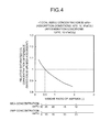
- FIG. 4 is a graph showing the relation between the relative saturated CO 2 concentration difference and the weight ratio of AMP to MEA in Test Example 2-1 in which the total amine concentration is 35% by weight.
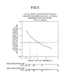
- FIG. 5 is a graph showing the relation between the relative saturated CO 2 concentration difference and the weight ratio of AMP to MEA in Test Example 2-2 in which the total amine concentration is 40% by weight.
- FIG. 6 is a graph showing the relation between the relative saturated CO 2 concentration difference and the weight ratio of AMP to MEA in Test Example 2-3 in which the total amine concentration is 45% by weight.
- a Comparative Example is a conventionally used absorbent containing monoethanolamine (MEA) alone.
- An absorbent containing MEA at a concentration of 30% by weight was used as a reference absorbent, and a reaction rate indicator was shown.
- reaction rate indicator reaction rate index of an absorbent in the subject application at a concentration in the Test Example / reaction rate index of the MEA absorbent 30 % by weight
- reaction rate index reaction rate constant ⁇ amine concentration ⁇ diffusion coefficient of CO 2 0.5
- Ethylenediamine (EDA), N,N'-dimethylethylenediamine (DMEDA), N,N'-diethylethylenediamine (DEEDA), propanediamine (PDA), N,N'-dimethylpropanediamine (DMPDA), piperazine (PZ), 1-methylpiperazine (1MPZ), 2-methylpiperazine (2MPZ), 2,5-dimethylpiperazine (DMPZ), 1-(2-aminoethyl)piperazine (AEPRZ), and 1-(2-hydroxyethyl)piperazine (HEP) were used as the assistant added.
- Ethylenediamine (EDA), N,N'-dimethylethylenediamine (DMEDA), N,N'-diethylethylenediamine (DEEDA), propanediamine (PDA), N,N'-dimethylpropanediamine (DMPDA), piperazine (PZ), 1-methylpiperazine (1MPZ), 2-methylpiperazine (2MPZ), 2,5-
- Test Example 3 the total amine concentration was 40% by weight.
- the absorption conditions in this test were 40°C and 10 kPa CO 2 .
- FIG. 7 is a graph showing the relation between the reaction rate indicator and the weight ratio of a polyamine to the primary amine in Test Example 3.
- reaction rate index of the 30 wt% MEA absorbent was used as a reference vale of "1," and the reaction rate indicator of each absorbent was shown.
- EDA ethylenediamine
- DMEDA N,N'-dimethylethylenediamine
- DEEDA propanediamine
- DMPDA N,N'-dimethylpropanediamine
- PZ 1-methylpiperazine (1MPZ), 2-methylpiperazine (2MPZ), 2,5-dimethylpiperazine (DMPZ), 1-(2-aminoethyl)piperazine (AEPRZ), and 1-(2-hydroxyethyl)piperazine (HEP)
- MEA monoethanolamine
- AMP 2-amino-2-methyl-1-propanol
- HEP 1-(2-hydroxyethyl)piperazine
Landscapes
- Chemical & Material Sciences (AREA)
- Engineering & Computer Science (AREA)
- Analytical Chemistry (AREA)
- Chemical Kinetics & Catalysis (AREA)
- General Chemical & Material Sciences (AREA)
- Oil, Petroleum & Natural Gas (AREA)
- Environmental & Geological Engineering (AREA)
- Health & Medical Sciences (AREA)
- Biomedical Technology (AREA)
- Organic Chemistry (AREA)
- Gas Separation By Absorption (AREA)
- Treating Waste Gases (AREA)
Abstract

Description
- The present invention relates to a complex amine absorbent and to a device and a method for removing one or both of CO2 and H2S.
- The greenhouse effect due to CO2 has recently been pointed out as a cause of global warming, and international measures to address the greenhouse effect are urgently needed to protect the global environment. Sources of CO2 emissions are present in all areas of human activity in which fossil fuel is combusted, and the demand for reducing CO2 emissions tends to further increase. To meet the demand in power generation facilities such as thermal power plants that use a large amount of fossil fuel, intensive research has been conducted on a method of removing and recovering CO2 in flue gas from a boiler by bringing the flue gas into contact with an amine-based CO2 absorbent and on a method of storing recovered CO2 with no emissions to the air. One process used to remove and recover CO2 in flue gas using such a CO2 absorbent described above includes the steps of bringing the flue gas into contact with the CO2 absorbent in an absorber, heating the absorbent containing CO2 absorbed therein in a regenerator to release CO2 and regenerate the absorbent, and recirculating the regenerated absorbent into the absorber to reuse the absorbent (see, for example, Patent Literature 1).
- With the method of absorbing, removing, and recovering CO2 in CO2-containing gas such as flue gas using the above-described CO2 absorbent and process, since the process is installed additionally in a combustion facility, it is necessary to reduce the operating cost of the process as much as possible. Particularly, the regeneration step in the above process consumes a large amount of thermal energy, and therefore the energy used in the process must be reduced as much as possible.
- In one prior proposal, part of a semi-lean solution is drawn off from a regenerator to the outside. The drawn semi-lean solution exchanges heat with a lean solution in a heat exchanger and then exchanges heat with steam-condensed water in another heat exchanger. The resultant semi-lean solution is returned to a position downward of the drawn-off position. The temperature of the semi-lean solution supplied to the lower side of the regenerator is increased, and the amount of steam consumed is thereby reduced (see, for example, Patent Literature 2 (
embodiment 8, FIG. 17)). - Regarding CO2 absorbents, in order to improve the performance thereof, absorbents contributing the improvement in their absorption performance have been proposed (
Patent Literatures 3 and 4). -
- Patent Literature 1: Japanese Laid-open Patent Publication No.
7-51537 - Patent Literature 2: Japanese Patent No.
4690659 - Patent Literature 3: Japanese Laid-open Patent Publication No.
2008-13400 - Patent Literature 4: Japanese Laid-open Patent Publication No.
2008-307519 - Important performance of a CO2 absorbent includes not only its absorption performance but also its releasing ability when the absorbent is regenerated. One current task is to propose an absorbent having good regeneration performance as well as improved absorption performance that has been extensively studied.
- As described above, steam is necessary to recover CO2 from flue gas. Therefore, to achieve energy saving by using a small amount of water vapor while a desired amount of CO2 is recovered, there is a strong demand for an absorbent having not only an absorption ability but also a regeneration ability, for the purpose of reducing operating cost.
- In view of the foregoing problems, it is an object of the present invention to provide a complex amine absorbent having not only an absorption ability but also a regeneration ability and a device and a method for removing one or both of CO2 and H2S.
- According to a first aspect of the present invention in order to solve the above-problems, there is provided a complex amine absorbent for absorbing one or both of CO2 and H2S in a gas, the complex amine absorbent including: 1) monoethanolamine (MEA), and 2) a primary amine represented by the following formula (1) and having high steric hindrance, with the monoethanolamine and the primary amine being dissolved in

R1 to R3: H or a hydrocarbon group having 1 to 3 carbon atoms, at least one of R1 to R3 being a hydrocarbon wherein R1 to R3 are each hydrogen or a hydrocarbon group having 1 to 3 carbon atoms, and at least one of the functional groups R1 to R3 is a hydrocarbon. - According to a second aspect of the present invention, there is provided the complex amine absorbent according to the first aspect, wherein the primary amine having high steric hindrance is at least one of 2-amino-1-propanol, 2-amino-1-butanol, 2-amino-3-methyl-1-butanol, 1-amino-2-propanol, 1-amino-2-butanol, and 2-amino-2-methyl-1-propanol.
- According to a third aspect of the present invention, there is provided the complex amine absorbent according to the first or second aspect, further including any one of at least one amine selected from linear poly primary and secondary amines and at least one amine selected from cyclic polyamines.
- According to a fourth aspect of the present invention, there is provided the complex amine absorbent according to the third aspect, wherein the linear poly primary and secondary amines are ethylenediamine, N,N'-dimethylethylenediamine, N,N'-diethylethylenediamine, propanediamine, and N,N'-dimethylpropanediamine, and
the cyclic polyamines are piperazine, 1-methylpiperazine, 2-methylpiperazine, 2,5-dimethylpiperazine, 1-(2-aminoethyl)piperazine, and 1-(2-hydroxyethyl)piperazine. - According to a fifth aspect of the present invention, there is provided the complex amine absorbent according to any one of the first to fourth aspects, wherein the complex amine absorbent is circulated and reused in an absorbing-removing facility including an absorber for absorbing one or both of CO2 and H2S in the gas and a regenerator in which the one or both of CO2 and H2S absorbed are released to regenerate the absorbent, a pressure inside the regenerator is 130 to 200 kPa (absolute pressure), an absorption temperature in the absorber is 30 to 80°C, and a regeneration temperature in the regenerator is 110°C or higher.
- According to a sixth aspect of the present invention, there is provided the device for removing one or both of CO2 and H2S, the device comprising: an absorber for removing one or both of CO2 and H2S by bringing a gas containing one or both of CO2 and H2S in contact with an absorbent; and a regenerator for regenerating a solution containing the one or both of CO2 and H2S absorbed therein, the solution regenerated by removing the one or both of CO2 and H2S in the regenerator being reused in the absorber, wherein the complex amine absorbent according to any one of the first to fifth aspects is used.
- According to a seventh aspect of the present invention, there is provided a method of removing one or both of CO2 and H2S, the method comprising: bringing a gas containing one or both of CO2 and H2S in contact with an absorbent to remove the one or both of CO2 and H2S; regenerating a solution containing one or both of CO2 and H2S absorbed therein; and reusing, in an absorber, the solution regenerated by removing the one or both of CO2 and H2S in a regenerator, wherein
the complex amine absorbent according to any one of the first to fifth aspects is used to remove the one or both of CO2 and H2S. - In the present invention, 1) monoethanolamine (MEA) and 2) a primary amine represented by the following formula (1) and having high steric hindrance are dissolved in water to prepare an absorbent. This absorbent has a high ability to release CO2 or H2S during regeneration of the absorbent, and therefore the amount of water vapor used in a facility for recovering CO2 or H2S during regeneration of the absorbent can be reduced.

-
-
FIG. 1 is a schematic diagram illustrating the configuration of a CO2 recovery unit according to a first embodiment. -
FIG. 2 is a graph showing the relation between relative saturated CO2 absorption capacity and the weight ratio of a sterically hindered primary amine to MEA in Test Example 1 when the total concentration of amines is 45% by weight. -
FIG. 3 is a graph showing the relation between relative saturated CO2 absorption capacity and the weight ratio of a sterically hindered primary amine to MEA in Test Example 1 when the total concentration of amines is 35% by weight. -
FIG. 4 is a graph showing the relation between relative saturated CO2 concentration difference and the weight ratio of AMP to MEA in Test Example 2 when the total concentration of amines is 35% by weight. -
FIG. 5 is a graph showing the relation between relative saturated CO2 concentration difference and the weight ratio of AMP to MEA in Test Example 2 when the total concentration of amines is 40% by weight. -
FIG. 6 is a graph showing the relation between relative saturated CO2 concentration difference and the weight ratio of AMP to MEA in Test Example 2 when the total concentration of amines is 45% by weight. -
FIG. 7 is a graph showing the relation between reaction rate indicator and the weight ratio of a polyamine to a primary amine in Test Example 3. - The present invention will next be described in detail with reference to the drawings. However, the present invention is not limited by this embodiment. When there are a plurality of embodiments, any combinations of the embodiments are included in the invention. Components in the following embodiments include those that can be easily devised by persons skilled in the art or that are substantially the same.
- A complex amine absorbent according to an embodiment of the present invention is an absorbent that absorbs one or both of CO2 and H2S in gas and is obtained by dissolving 1) monoethanolamine (MEA) and 2) a primary amine represented by the following formula (1) and having high steric hindrance, in water.

- Herein, R1 to R3 are each hydrogen or a hydrocarbon group having 1 to 3 carbon atoms, and at least one of the functional groups R1 to R3 is a hydrocarbon.
- The total concentration of amine absorbents in the complex amine absorbent is preferably 30 to 70% by weight and more preferably 40 to 70% by weight.
- In the present invention, 1) monoethanolamine (MEA) and 2) the primary amine represented by the above-mentioned formula (1) and having high steric hindrance are dissolved in water to prepare the absorbent. These amines are entangled in a complex manner, and the synergistic effect of these amines provides high ability to absorb one or both of CO2 and H2S and high ability to release absorbed CO2 or H2S during regeneration of the absorbent, so that the amount of water vapor used in a CO2 recovery facility during regeneration of the absorbent can be reduced.
- The primary amine represented by the above-mentioned formula (1) and having high steric hindrance may be, for example, any one of 2-amino-1-propanol (2A1P), 2-amino-1-butanol (2A1B), 2-amino-3-methyl-1-butanol (AMB), 1-amino-2-propanol (1A2P), 1-amino-2-butanol (1A2B), and 2-amino-2-methyl-1-propanol (AMP).
- A combination of the above amines may be used.
- When a combination of amines is used, it is preferable to use an absorbent containing 2-amino-2-methyl-1-propanol (AMP) as a base amine and another amine added thereto.
- The total concentration of amines in the complex amine absorbent is preferably 30 to 70% by weight. This is because, when the total concentration of amines falls outside this range, the complex amine absorbent does not favorably function as an absorbent.
- The weight ratio of 2) the primary amine having high steric hindrance to 1) monoethanolamine (MEA) is within the range of 0.3 to 2.5, preferably within the range of 0.3 to 1.2, and more preferably within the range of 0.3 to 0.7.
- This is because, as described in Test Examples later, absorption performance becomes lower than reference absorption performance, i.e., the absorption performance when the concentration of MEA is 30% by weight, which is a concentration generally used in conventional absorbents.
- The above ratio is changed according to the total amine concentration. When the total amine concentration is 30% by weight, the ratio is a value close to 0.3.
- Any one of at least one amine selected from linear poly primary and secondary amines and at least one selected from cyclic polyamines may be further contained as an assistant.
The addition of the assistant improves the rate of reaction, so that energy saving can be achieved. - Preferably, the linear poly primary and secondary amines are ethylenediamine (EDA), N,N'-dimethylethylenediamine (DMEDA), N,N'-diethylethylenediamine (DEEDA), propanediamine (PDA), and N,N'-dimethylpropanediamine (DMPDA), and the cyclic polyamines are piperazine (PZ), 1-methylpiperazine (1MPZ), 2-methylpiperazine (2MPZ), 2,5-dimethylpiperazine (DMPZ), 1-(2-aminoethyl)piperazine (AEPRZ), and 1-(2-hydroxyethyl)piperazine (HEP).
- Preferably, the weight ratio of "at least one amine selected from the linear poly primary and secondary amines or at least one amine selected from the cyclic polyamines" to "the complex primary amine absorbent containing monoethanolamine and at least one amine selected from primary amines having high steric hindrance" (the weight ratio of the polyamine / the complex primary amine) is 1 or less.
- In the present invention, absorption temperature in an absorber during contact with flue gas containing CO2 etc. is generally within the range of preferably 30 to 80°C. If necessary, an anti-corrosive agent, an anti-degradant, etc. are added to the absorbent used in the present invention.
- In the present invention, regeneration temperature in a regenerator in which CO2 etc. are released from the absorbent containing CO2 etc. absorbed therein is preferably 110°C or higher when the pressure inside the regenerator is 130 to 200 kPa (absolute pressure). This is because, when regeneration is performed below 110°C, the amount of the absorbent circulating in the system must be increased, and this is not preferred in terms of regeneration efficiency.
- More preferably, regeneration is performed at 120°C or higher.
- Examples of the gas treated by the present invention include coal gasification gases, synthesis gases, coke-oven gases, petroleum gases, and natural gases, but the gas treated is not limited thereto. Any gas may be used so long as it contains an acid gas such as CO2 or H2S.
- No particular limitation is imposed on a process that can be used in a method of removing one or both of CO2 and H2S in the gas in the present invention. An example of a removing device for removing CO2 will be described with reference to
FIG. 1 . -
FIG. 1 is a schematic diagram illustrating the configuration of a CO2 recovery unit according toembodiment 1. As shown inFIG. 1 , a CO2 recovery unit 12 according toembodiment 1 includes: a fluegas cooling unit 16 for cooling, with coolingwater 15,flue gas 14 containing CO2 and O2 discharged from anindustrial combustion facility 13 such as a boiler or a gas turbine; a CO2 absorber 18 including a CO2 recovery section 18A for removing CO2 from theflue gas 14 by bringing the cooledflue gas 14 containing CO2 into contact with a CO2 absorbent 17 (hereinafter may be referred to as an "absorbent") that absorbs CO2; and anabsorbent regenerator 20 for regenerating the CO2 absorbent by causing the CO2 absorbent 19 containing CO2 absorbed therein (hereinafter, this absorbent may also be referred to as a "rich solution") to release CO2. In the CO2 recovery unit 12, the regenerated CO2 absorbent 17 from which CO2 has been removed in the absorbent regenerator 20 (hereinafter, this absorbent may also be referred to as a "lean solution") is reused in the CO2 absorber 18 as the CO2 absorbent. - In
FIG. 1 ,reference numeral 13a represents a flue gas duct, 13b represents a stack, and 34 represents steam-condensed water. The CO2 recovery unit may be retrofitted to an existing flue gas source to recover CO2 therefrom or may be installed together with a new flue gas source. An open-close damper is disposed in a line for theflue gas 14 and is opened during operation of the CO2 recovery unit 12. When the flue gas source is in operation but the operation of the CO2 recovery unit 12 is stopped, the damper is set to be closed. - In a CO2 recovery method using the CO2 recovery unit 12, the
flue gas 14 containing CO2 and supplied from theindustrial combustion facility 13 such as a boiler or a gas turbine is first increased in pressure by aflue gas blower 22, then supplied to the fluegas cooling unit 16, cooled with the coolingwater 15 in the fluegas cooling unit 16, and then supplied to the CO2 absorber 18. - In the CO2 absorber 18, the
flue gas 14 comes into countercurrent contact with the CO2 absorbent 17 serving as an amine absorbent according to this embodiment, and the CO2 in theflue gas 14 is absorbed by the CO2 absorbent 17 through a chemical reaction. - The CO2-removed flue gas from which CO2 has been removed in the CO2 recovery section 18A comes into gas-liquid contact with circulating
wash water 21 containing the CO2 absorbent and supplied from a nozzle in awater washing section 18B in the CO2 absorber 18, and the CO2 absorbent 17 entrained in the CO2-removed flue gas is thereby recovered. Then aflue gas 23 from which CO2 has been removed is discharged to the outside of the system. - The rich solution, which is the CO2 absorbent 19 containing CO2 absorbed therein, is increased in presser by a
rich solution pump 24, heated by the lean solution, which is the CO2 absorbent 17 regenerated in theabsorbent regenerator 20, in a rich-leansolution heat exchanger 25, and then supplied to theabsorbent regenerator 20. - The
rich solution 19 released into theabsorbent regenerator 20 from its upper portion undergoes an endothermic reaction due to water vapor supplied from the bottom portion, and most CO2 is released. The CO2 absorbent that has released part or most of CO2 in theabsorbent regenerator 20 is referred to as a semi-lean solution. The semi-lean solution becomes the CO2 absorbent (lean solution) 17 from which almost all CO2 has been removed when the semi-lean solution reaches the bottom of theabsorbent regenerator 20. Part of thelean solution 17 is superheated bywater vapor 27 in aregeneration superheater 26 to supply water vapor to the inside of theregenerator 20. - CO2-entrained gas 28 accompanied by water vapor produced from the
rich solution 19 and semi-lean solution in theabsorbent regenerator 20 is discharged from the vertex portion of theabsorbent regenerator 20. The water vapor is condensed in acondenser 29, and water is separated by aseparation drum 30. CO2 gas 40 is discharged to the outside of the system, compressed by aseparate compressor 41, and then recovered. A compressed and recovered CO2 gas 42 passes through aseparation drum 43 and then injected into an oil field using Enhanced Oil Recovery (EOR) or reserved in an aquifer to address global warming. - A
reflux water 31 separated from the CO2-entrained gas 28 accompanied by water vapor in theseparation drum 30 and refluxed therethrough is supplied to the upper portion of theabsorbent regenerator 20 through a refluxwater circulation pump 35 and also supplied as the circulatingwash water 21. - The regenerated CO2 absorbent (lean solution) 17 is cooled by the
rich solution 19 in the rich-leansolution heat exchanger 25, then increased in pressure by alean solution pump 32, cooled in a lean solution cooler 33, and then supplied to the CO2 absorber 18. In the embodiment, their outlines have been described, and part of attachments is omitted in the description. - Preferred Test Examples showing the effects of the present invention will next be described, but the present invention is not limited thereto.
- An unillustrated absorption device was used for absorption of CO2.
FIGS. 2 and3 are graphs showing the relation between relative saturated CO2 absorption capacity and the weight ratio of a sterically hindered primary amine to MEA in Test Example 1. - A Comparative Example is a conventionally used absorbent containing monoethanolamine (MEA) alone.
- An absorbent containing MEA at a concentration of 30% by weight was used as a reference absorbent, and a relative saturated CO2 absorption capacity was shown.
- The relative saturated CO2 absorption capacity is determined as follows.

- In Test Example 1, one of 2-amino-1-propanol (2A1P), 2-amino-1-butanol (2A1B), 2-amino-3-methyl-1-butanol (AMB), 1-amino-2-propanol (1A2P), and 2-amino-2-methyl-1-propanol (AMP) was used as the primary amine having high steric hindrance at a mixing ratio shown in a lower part of
FIG. 2 . The amines were dissolved in water and mixed to prepare respective absorbents. - The total amine concentration in Test Example 1 was 45% by weight.
- The absorption conditions in this test were 40°C and 10 kPa CO2.
- In
FIG. 2 , the saturated CO2 absorption capacity of the 30 wt% MEA absorbent was used as a reference value of "1," and the relative saturated CO2 absorption capacity of each absorbent was shown. - As shown in
FIG. 2 , for all the four primary amines having high steric hindrance (2-amino-1-propanol (2A1P), 2-amino-1-butanol (2A1B), 2-amino-3-methyl-1-butanol (AMB), 1-amino-2-propanol (1A2P), and 2-amino-2-methyl-1-propanol (AMP)), the relative saturated CO2 absorption capacity was higher than the reference value "1," and the absorption performance was found to be good. - Of these, 2-amino-2-methyl-1-propanol (AMP), in particular, showed a very high value for the absorption performance.
- As shown in
FIG. 3 , even when the total amine concentration was changed from 45% by weight to 35% by weight, the relative saturated CO2 absorption capacity of the amine solution using a combination of monoethanolamine (MEA) and 2-amino-2-methyl-1-propanol (AMP) was higher than a reference value of "1," and the absorption performance was found to be good. - A Comparative Example is a conventionally used absorbent containing monoethanolamine (MEA) alone.
- An absorbent containing MEA at a concentration of 30% by weight was used as a reference absorbent, and a relative saturated CO2 concentration difference was shown.
- The relative saturated CO2 concentration difference is determined as follows.

- The saturated CO2 concentration difference is determined as follows.
- Saturated CO2 concentration difference = saturated CO2 concentration under absorption conditions - saturated CO2 concentration under recovery conditions
- In Test Example 2, 2-amino-2-methyl-1-propanol (AMP) was used as the primary amine having high steric hindrance at a mixing ratio shown in a lower part of each of
FIGS. 3 and4 . The amines were dissolved in water and mixed to prepare respective absorbents. - The total amine concentration in Test Example 2-1 was 35% by weight (see
FIG. 4 ). - The total amine concentration in Test Example 2-2 was 40% by weight (see
FIG. 5 ). - The total amine concentration in Test Example 2-3 was 45% by weight (see
FIG. 6 ). - The absorption conditions in the test were 40°C and 10 kPa CO2.
- The recovery conditions were 120°C and 10 kPa CO2.
-
FIG. 4 is a graph showing the relation between the relative saturated CO2 concentration difference and the weight ratio of AMP to MEA in Test Example 2-1 in which the total amine concentration is 35% by weight.FIG. 5 is a graph showing the relation between the relative saturated CO2 concentration difference and the weight ratio of AMP to MEA in Test Example 2-2 in which the total amine concentration is 40% by weight.FIG. 6 is a graph showing the relation between the relative saturated CO2 concentration difference and the weight ratio of AMP to MEA in Test Example 2-3 in which the total amine concentration is 45% by weight. - In
FIG. 4 to FIG. 6 , the saturated CO2 absorption capacity of the 30 wt% MEA absorbent was used as a reference value of "1," and the relative saturated CO2 absorption capacity of each absorbent was shown. - As shown in
FIG. 4 , in Test Example 2-1 in which 2-amino-2-methyl-1-propanol (AMP)) was used as the primary amine having high steric hindrance, the relative saturated CO2 concentration difference was higher than a reference value of "1" when the weight ratio was about 0.5 or less, and the absorption performance was found to be good. - As shown in
FIG. 5 , in Test Example 2-2 in which 2-amino-2-methyl-1-propanol (AMP) was used as the primary amine having high steric hindrance, the relative saturated CO2 concentration difference was higher than a reference value of "1" when the weight ratio was about 1.2 or less, and the absorption performance was found to be good. - When the weight ratio was about 0.7 or less, the relative saturated CO2 concentration difference was significantly higher than a reference value of "1" (an improvement of about 10%), and the absorption performance was found to be better.
- As shown in
FIG. 6 , in Test Example 2-3 in which 2-amino-2-methyl-1-propanol (AMP) was used as the primary amine having high steric hindrance, the relative saturated CO2 concentration difference was higher than a reference value of "1" when the weight ratio was about 2.5 or less, and the absorption performance was found to be good. - A Comparative Example is a conventionally used absorbent containing monoethanolamine (MEA) alone.
- An absorbent containing MEA at a concentration of 30% by weight was used as a reference absorbent, and a reaction rate indicator was shown.
- The reaction rate indicator is determined as follows.

- The reaction rate index is determined as follows.

- In Test Example 3, 2-amino-2-methyl-1-propanol (AMP) was used as the primary amine having high steric hindrance, and a polyamine used as an assistant was added at a mixing ratio shown in a lower part of
FIG. 7 . These were dissolved in water and mixed to prepare an absorbent. - Ethylenediamine (EDA), N,N'-dimethylethylenediamine (DMEDA), N,N'-diethylethylenediamine (DEEDA), propanediamine (PDA), N,N'-dimethylpropanediamine (DMPDA), piperazine (PZ), 1-methylpiperazine (1MPZ), 2-methylpiperazine (2MPZ), 2,5-dimethylpiperazine (DMPZ), 1-(2-aminoethyl)piperazine (AEPRZ), and 1-(2-hydroxyethyl)piperazine (HEP) were used as the assistant added.
- In Test Example 3, the total amine concentration was 40% by weight.
- The absorption conditions in this test were 40°C and 10 kPa CO2.
- The results are shown in
FIG. 7. FIG. 7 is a graph showing the relation between the reaction rate indicator and the weight ratio of a polyamine to the primary amine in Test Example 3. - In
FIG. 7 , the reaction rate index of the 30 wt% MEA absorbent was used as a reference vale of "1," and the reaction rate indicator of each absorbent was shown. - As shown in
FIG. 7 , when any of the assistants (ethylenediamine (EDA), N,N'-dimethylethylenediamine (DMEDA), N,N'-diethylethylenediamine (DEEDA), propanediamine (PDA), N,N'-dimethylpropanediamine (DMPDA), piperazine (PZ), 1-methylpiperazine (1MPZ), 2-methylpiperazine (2MPZ), 2,5-dimethylpiperazine (DMPZ), 1-(2-aminoethyl)piperazine (AEPRZ), and 1-(2-hydroxyethyl)piperazine (HEP)) was added to the complex primary amine composed of monoethanolamine (MEA) and the primary amine having high steric hindrance (2-amino-2-methyl-1-propanol (AMP)), the reaction rate indicator was higher than a reference value of "1," and the absorption performance was found to be good. - Of these, N,N'-dimethylethylenediamine (DMEDA) and N,N'-dimethylpropanediamine (DMPDA), in particular, showed high reaction rate values.
-
- 12
- CO2 recovery unit
- 13
- Industrial combustion facility
- 14
- Flue gas
- 16
- Flue gas cooling unit
- 17
- CO2 absorbent (lean solution)
- 18
- CO2 absorber
- 19
- CO2 absorbent containing CO2 absorbed therein (rich solution)
- 20
- Absorbent regenerator
- 21
- Wash water
Claims (7)
- A complex amine absorbent for absorbing one or both of CO2 and H2S in a gas, the complex amine absorbent comprising1) monoethanolamine (MEA), and2) a primary amine represented by the following formula (1) and having high steric hindrance, with the monoethanolamine and the primary amine being dissolved in water,

wherein R1 to R3 are each hydrogen or a hydrocarbon group having 1 to 3 carbon atoms, and at least one of the functional groups R1 to R3 is a hydrocarbon. - The complex amine absorbent according to claim 1, wherein the primary amine having high steric hindrance is at least one of 2-amino-1-propanol, 2-amino-1-butanol, 2-amino-3-methyl-1-butanol, 1-amino-2-propanol, 1-amino-2-butanol, and 2-amino-2-methyl-1-propanol.
- The complex amine absorbent according to claim 1 or 2, further comprising any one of at least one amine selected from linear poly primary and secondary amines and at least one amine selected from cyclic polyamines.
- The complex amine absorbent according to claim 3,
wherein
the linear poly primary and secondary amines are ethylenediamine, N,N'-dimethylethylenediamine, N,N'-diethylethylenediamine, propanediamine, and N,N'-dimethylpropanediamine, and
the cyclic polyamines are piperazine, 1-methylpiperazine, 2-methylpiperazine, 2,5-dimethylpiperazine, 1-(2-aminoethyl)piperazine, and 1-(2-hydroxyethyl)piperazine. - The complex amine absorbent according to any one of claims 1 to 4, wherein
the complex amine absorbent is circulated and reused in an absorbing-removing facility including an absorber for absorbing one or both of CO2 and H2S in the gas and a regenerator in which the one or both of CO2 and H2S absorbed are released to regenerate the absorbent,
a pressure inside the regenerator is 130 to 200 kPa (absolute pressure),
an absorption temperature in the absorber is 30 to 80°C, and
a regeneration temperature in the regenerator is 110°C or higher. - A device for removing one or both of CO2 and H2S, the device comprising: an absorber for removing one or both of CO2 and H2S by bringing a gas containing one or both of CO2 and H2S in contact with an absorbent; and a regenerator for regenerating a solution containing the one or both of CO2 and H2S absorbed therein, the solution regenerated by removing the one or both of CO2 and H2S in the regenerator being reused in the absorber, wherein
the complex amine absorbent according to any one of claims 1 to 5 is used. - A method of removing one or both of CO2 and H2S, the method comprising: bringing a gas containing one or both of CO2 and H2S in contact with an absorbent to remove the one or both of CO2 and H2S; regenerating a solution containing one or both of CO2 and H2S absorbed therein; and reusing, in an absorber, the solution regenerated by removing the one or both of CO2 and H2S in a regenerator, wherein
the complex amine absorbent according to any one of claims 1 to 5 is used to remove the one or both of CO2 and H2S.
Applications Claiming Priority (2)
| Application Number | Priority Date | Filing Date | Title |
|---|---|---|---|
| JP2012109948A JP5986796B2 (en) | 2012-05-11 | 2012-05-11 | Apparatus and method for removing complex amine absorbing liquid, CO2 and / or H2S |
| PCT/JP2013/062259 WO2013168588A1 (en) | 2012-05-11 | 2013-04-25 | Composite amine absorbing solution, and device and method for removing co2, h2s, or both |
Publications (3)
| Publication Number | Publication Date |
|---|---|
| EP2848298A1 true EP2848298A1 (en) | 2015-03-18 |
| EP2848298A4 EP2848298A4 (en) | 2016-02-17 |
| EP2848298B1 EP2848298B1 (en) | 2018-12-26 |
Family
ID=49550634
Family Applications (1)
| Application Number | Title | Priority Date | Filing Date |
|---|---|---|---|
| EP13788078.7A Active EP2848298B1 (en) | 2012-05-11 | 2013-04-25 | Composite amine absorbing solution and method for removing co2, h2s, or both |
Country Status (6)
| Country | Link |
|---|---|
| US (1) | US10137407B2 (en) |
| EP (1) | EP2848298B1 (en) |
| JP (1) | JP5986796B2 (en) |
| AU (1) | AU2013258901B2 (en) |
| CA (1) | CA2872593C (en) |
| WO (1) | WO2013168588A1 (en) |
Families Citing this family (6)
| Publication number | Priority date | Publication date | Assignee | Title |
|---|---|---|---|---|
| JP6841676B2 (en) | 2017-01-31 | 2021-03-10 | 三菱重工エンジニアリング株式会社 | Complex amine absorber, CO2 and / or H2S removal device and method |
| GB201813839D0 (en) * | 2018-06-26 | 2018-10-10 | Carbon Clean Solutions Ltd | System and process of capturing carbon dioxide from flue gases |
| CN113457382A (en) * | 2021-07-22 | 2021-10-01 | 浙江天地环保科技股份有限公司 | Low-viscosity CO2Trapping mixed absorbent formulation |
| CA3230405A1 (en) | 2021-08-31 | 2023-03-09 | Dean TAKAHASHI | Systems and methods for carbon sequestration using enhanced weathering |
| CN116371146B (en) * | 2023-02-24 | 2026-02-13 | 国家能源集团新能源技术研究院有限公司 | Carbon dioxide absorbent and preparation method and application thereof |
| CN116272262A (en) * | 2023-05-11 | 2023-06-23 | 上海交通大学 | A kind of ternary mixed amine type carbon dioxide absorber and its preparation method and application |
Family Cites Families (26)
| Publication number | Priority date | Publication date | Assignee | Title |
|---|---|---|---|---|
| AU506199B2 (en) | 1975-06-26 | 1979-12-20 | Exxon Research And Engineering Company | Absorbtion of co2 from gaseous feeds |
| DE2551717C3 (en) * | 1975-11-18 | 1980-11-13 | Basf Ag, 6700 Ludwigshafen | and possibly COS from gases |
| CA1091429A (en) * | 1977-01-06 | 1980-12-16 | Guido Sartori | Process for removing carbon dioxide containing acidic gases from gaseous mixtures |
| US4100257A (en) * | 1977-02-14 | 1978-07-11 | Exxon Research & Engineering Co. | Process and amine-solvent absorbent for removing acidic gases from gaseous mixtures |
| US4100099A (en) * | 1977-03-28 | 1978-07-11 | The Dow Chemical Company | Quaternary salt-polyamine inhibitor for sour gas conditioning solutions |
| JPH0644972B2 (en) * | 1988-03-11 | 1994-06-15 | ユニオン・カーバイド・コーポレーション | Tertiary alkanolamine absorbers containing ethylene amine promoters and methods of use thereof |
| JPH04349921A (en) * | 1991-05-27 | 1992-12-04 | Mitsubishi Heavy Ind Ltd | Exhaust gas decarbonizing absorbent |
| JP2809368B2 (en) * | 1993-04-05 | 1998-10-08 | 関西電力株式会社 | Method for recovering carbon dioxide from flue gas |
| JPH06343858A (en) * | 1993-06-08 | 1994-12-20 | Mitsubishi Heavy Ind Ltd | Carbon dioxide absorbent |
| JPH0751537A (en) | 1993-06-30 | 1995-02-28 | Mitsubishi Heavy Ind Ltd | Removal of co2 in co2-containing gas |
| DE19828977A1 (en) * | 1998-06-29 | 1999-12-30 | Basf Ag | Absorbent for removing acidic components from gases |
| US6165433A (en) * | 1999-06-10 | 2000-12-26 | Praxair Technology, Inc. | Carbon dioxide recovery with composite amine blends |
| JP4690659B2 (en) | 2004-03-15 | 2011-06-01 | 三菱重工業株式会社 | CO2 recovery device |
| US7368476B2 (en) * | 2004-04-07 | 2008-05-06 | Pharmacyclics, Inc. | Hydroxamates as therapeutic agents |
| DE112007000375B4 (en) * | 2006-02-14 | 2021-01-07 | Basf Se | Process for removing acidic gases and processes for retrofitting plants for removing acidic gases |
| WO2007104800A1 (en) * | 2006-03-16 | 2007-09-20 | Basf Se | Process for contacting two phases whose contact is accompanied by heat evolution |
| JP5230080B2 (en) | 2006-06-06 | 2013-07-10 | 三菱重工業株式会社 | Absorption liquid, CO2 removal apparatus and method |
| JP2008013400A (en) | 2006-07-05 | 2008-01-24 | Research Institute Of Innovative Technology For The Earth | Method for absorbing and desorbing carbon dioxide in exhaust gas |
| US7901488B2 (en) * | 2006-10-04 | 2011-03-08 | Board Of Regents, The University Of Texas System | Regeneration of an aqueous solution from an acid gas absorption process by matrix stripping |
| JP5215595B2 (en) | 2007-06-18 | 2013-06-19 | 三菱重工業株式会社 | Absorbing liquid, CO2 or H2S removing apparatus and method using absorbing liquid |
| DK2300127T3 (en) * | 2008-06-23 | 2015-07-06 | Basf Se | ABSORPENT AND PROCEDURE FOR THE REMOVAL OF ACID GASES FROM LIQUID FLOWS, PARTICULARLY FROM Flue gases |
| KR101035148B1 (en) * | 2008-10-28 | 2011-05-17 | 한국전력공사 | Absorbent for acid gas separation |
| CA2761895C (en) * | 2009-05-26 | 2018-08-28 | Basf Se | Process for recovery of carbon dioxide from a fluid stream, in particular from syngas |
| DE102010004073A1 (en) * | 2010-01-05 | 2011-07-07 | Uhde GmbH, 44141 | CO2 removal from gases with low CO2 partial pressures by means of 1,2 diaminopropane |
| WO2011121635A1 (en) * | 2010-03-29 | 2011-10-06 | 株式会社 東芝 | Acidic gas absorbent, acidic gas removal device, and acidic gas removal method |
| US9266102B2 (en) * | 2013-03-29 | 2016-02-23 | The University Of Kentucky Research Foundation | Catalysts and methods of increasing mass transfer rate of acid gas scrubbing solvents |
-
2012
- 2012-05-11 JP JP2012109948A patent/JP5986796B2/en active Active
-
2013
- 2013-04-25 WO PCT/JP2013/062259 patent/WO2013168588A1/en not_active Ceased
- 2013-04-25 AU AU2013258901A patent/AU2013258901B2/en active Active
- 2013-04-25 EP EP13788078.7A patent/EP2848298B1/en active Active
- 2013-04-25 US US14/399,107 patent/US10137407B2/en active Active
- 2013-04-25 CA CA2872593A patent/CA2872593C/en active Active
Also Published As
| Publication number | Publication date |
|---|---|
| AU2013258901A1 (en) | 2014-11-27 |
| AU2013258901B2 (en) | 2016-07-14 |
| JP5986796B2 (en) | 2016-09-06 |
| US20150132207A1 (en) | 2015-05-14 |
| EP2848298A4 (en) | 2016-02-17 |
| US10137407B2 (en) | 2018-11-27 |
| CA2872593A1 (en) | 2013-11-14 |
| CA2872593C (en) | 2017-12-12 |
| EP2848298B1 (en) | 2018-12-26 |
| WO2013168588A1 (en) | 2013-11-14 |
| JP2013236987A (en) | 2013-11-28 |
Similar Documents
| Publication | Publication Date | Title |
|---|---|---|
| JP6172884B2 (en) | Three-component absorbent, CO2 and / or H2S removal device and method | |
| EP2848298B1 (en) | Composite amine absorbing solution and method for removing co2, h2s, or both | |
| JP2013086079A5 (en) | ||
| US8147593B2 (en) | Absorbing solution, method and device for absorbing CO2 or H2S or both | |
| AU2019423879B2 (en) | Composite amine absorption solution, and device and method both for removing CO2 or H2S or both of them | |
| AU2018214922B2 (en) | Composite amine absorbing solution, and device and method for removing CO2 or H2S or both | |
| JP5737916B2 (en) | CO2 recovery system | |
| JP2013236987A5 (en) | ||
| AU2014335384B2 (en) | Composite amine absorption solution, and method and device for removing CO2 and/or H2S | |
| KR102844542B1 (en) | Complex amine absorbent, removal device and removal method | |
| AU2020270596A1 (en) | Absorbing liquid for CO2, H2S, or both, and device and method for removing CO2, H2S, or both | |
| AU2012327104B9 (en) | 3-component absorbent solution, and CO2 and/or H2S removal device and method | |
| KR20260037133A (en) | Complex amine absorption solution | |
| AU2022335124A1 (en) | Composite amine absorbing liquid, removal apparatus, and removal method |
Legal Events
| Date | Code | Title | Description |
|---|---|---|---|
| PUAI | Public reference made under article 153(3) epc to a published international application that has entered the european phase |
Free format text: ORIGINAL CODE: 0009012 |
|
| 17P | Request for examination filed |
Effective date: 20141110 |
|
| AK | Designated contracting states |
Kind code of ref document: A1 Designated state(s): AL AT BE BG CH CY CZ DE DK EE ES FI FR GB GR HR HU IE IS IT LI LT LU LV MC MK MT NL NO PL PT RO RS SE SI SK SM TR |
|
| AX | Request for extension of the european patent |
Extension state: BA ME |
|
| DAX | Request for extension of the european patent (deleted) | ||
| RA4 | Supplementary search report drawn up and despatched (corrected) |
Effective date: 20160119 |
|
| RIC1 | Information provided on ipc code assigned before grant |
Ipc: B01D 53/14 20060101AFI20160113BHEP Ipc: B01D 53/62 20060101ALI20160113BHEP Ipc: B01D 53/77 20060101ALI20160113BHEP Ipc: B01D 53/52 20060101ALI20160113BHEP Ipc: B01D 53/34 20060101ALI20160113BHEP |
|
| STAA | Information on the status of an ep patent application or granted ep patent |
Free format text: STATUS: EXAMINATION IS IN PROGRESS |
|
| 17Q | First examination report despatched |
Effective date: 20170510 |
|
| GRAP | Despatch of communication of intention to grant a patent |
Free format text: ORIGINAL CODE: EPIDOSNIGR1 |
|
| STAA | Information on the status of an ep patent application or granted ep patent |
Free format text: STATUS: GRANT OF PATENT IS INTENDED |
|
| INTG | Intention to grant announced |
Effective date: 20180710 |
|
| RAP1 | Party data changed (applicant data changed or rights of an application transferred) |
Owner name: MITSUBISHI HEAVY INDUSTRIES ENGINEERING, LTD. Owner name: THE KANSAI ELECTRIC POWER CO., INC. |
|
| GRAS | Grant fee paid |
Free format text: ORIGINAL CODE: EPIDOSNIGR3 |
|
| GRAA | (expected) grant |
Free format text: ORIGINAL CODE: 0009210 |
|
| STAA | Information on the status of an ep patent application or granted ep patent |
Free format text: STATUS: THE PATENT HAS BEEN GRANTED |
|
| AK | Designated contracting states |
Kind code of ref document: B1 Designated state(s): AL AT BE BG CH CY CZ DE DK EE ES FI FR GB GR HR HU IE IS IT LI LT LU LV MC MK MT NL NO PL PT RO RS SE SI SK SM TR |
|
| REG | Reference to a national code |
Ref country code: GB Ref legal event code: FG4D |
|
| REG | Reference to a national code |
Ref country code: CH Ref legal event code: EP |
|
| REG | Reference to a national code |
Ref country code: AT Ref legal event code: REF Ref document number: 1080632 Country of ref document: AT Kind code of ref document: T Effective date: 20190115 |
|
| REG | Reference to a national code |
Ref country code: DE Ref legal event code: R096 Ref document number: 602013048865 Country of ref document: DE |
|
| REG | Reference to a national code |
Ref country code: IE Ref legal event code: FG4D |
|
| REG | Reference to a national code |
Ref country code: NL Ref legal event code: FP |
|
| PG25 | Lapsed in a contracting state [announced via postgrant information from national office to epo] |
Ref country code: LV Free format text: LAPSE BECAUSE OF FAILURE TO SUBMIT A TRANSLATION OF THE DESCRIPTION OR TO PAY THE FEE WITHIN THE PRESCRIBED TIME-LIMIT Effective date: 20181226 Ref country code: FI Free format text: LAPSE BECAUSE OF FAILURE TO SUBMIT A TRANSLATION OF THE DESCRIPTION OR TO PAY THE FEE WITHIN THE PRESCRIBED TIME-LIMIT Effective date: 20181226 Ref country code: HR Free format text: LAPSE BECAUSE OF FAILURE TO SUBMIT A TRANSLATION OF THE DESCRIPTION OR TO PAY THE FEE WITHIN THE PRESCRIBED TIME-LIMIT Effective date: 20181226 Ref country code: BG Free format text: LAPSE BECAUSE OF FAILURE TO SUBMIT A TRANSLATION OF THE DESCRIPTION OR TO PAY THE FEE WITHIN THE PRESCRIBED TIME-LIMIT Effective date: 20190326 Ref country code: LT Free format text: LAPSE BECAUSE OF FAILURE TO SUBMIT A TRANSLATION OF THE DESCRIPTION OR TO PAY THE FEE WITHIN THE PRESCRIBED TIME-LIMIT Effective date: 20181226 |
|
| REG | Reference to a national code |
Ref country code: LT Ref legal event code: MG4D |
|
| REG | Reference to a national code |
Ref country code: NO Ref legal event code: T2 Effective date: 20181226 |
|
| PG25 | Lapsed in a contracting state [announced via postgrant information from national office to epo] |
Ref country code: RS Free format text: LAPSE BECAUSE OF FAILURE TO SUBMIT A TRANSLATION OF THE DESCRIPTION OR TO PAY THE FEE WITHIN THE PRESCRIBED TIME-LIMIT Effective date: 20181226 Ref country code: SE Free format text: LAPSE BECAUSE OF FAILURE TO SUBMIT A TRANSLATION OF THE DESCRIPTION OR TO PAY THE FEE WITHIN THE PRESCRIBED TIME-LIMIT Effective date: 20181226 Ref country code: GR Free format text: LAPSE BECAUSE OF FAILURE TO SUBMIT A TRANSLATION OF THE DESCRIPTION OR TO PAY THE FEE WITHIN THE PRESCRIBED TIME-LIMIT Effective date: 20190327 Ref country code: AL Free format text: LAPSE BECAUSE OF FAILURE TO SUBMIT A TRANSLATION OF THE DESCRIPTION OR TO PAY THE FEE WITHIN THE PRESCRIBED TIME-LIMIT Effective date: 20181226 |
|
| REG | Reference to a national code |
Ref country code: AT Ref legal event code: MK05 Ref document number: 1080632 Country of ref document: AT Kind code of ref document: T Effective date: 20181226 |
|
| PG25 | Lapsed in a contracting state [announced via postgrant information from national office to epo] |
Ref country code: CZ Free format text: LAPSE BECAUSE OF FAILURE TO SUBMIT A TRANSLATION OF THE DESCRIPTION OR TO PAY THE FEE WITHIN THE PRESCRIBED TIME-LIMIT Effective date: 20181226 Ref country code: PT Free format text: LAPSE BECAUSE OF FAILURE TO SUBMIT A TRANSLATION OF THE DESCRIPTION OR TO PAY THE FEE WITHIN THE PRESCRIBED TIME-LIMIT Effective date: 20190426 Ref country code: PL Free format text: LAPSE BECAUSE OF FAILURE TO SUBMIT A TRANSLATION OF THE DESCRIPTION OR TO PAY THE FEE WITHIN THE PRESCRIBED TIME-LIMIT Effective date: 20181226 Ref country code: ES Free format text: LAPSE BECAUSE OF FAILURE TO SUBMIT A TRANSLATION OF THE DESCRIPTION OR TO PAY THE FEE WITHIN THE PRESCRIBED TIME-LIMIT Effective date: 20181226 |
|
| PG25 | Lapsed in a contracting state [announced via postgrant information from national office to epo] |
Ref country code: RO Free format text: LAPSE BECAUSE OF FAILURE TO SUBMIT A TRANSLATION OF THE DESCRIPTION OR TO PAY THE FEE WITHIN THE PRESCRIBED TIME-LIMIT Effective date: 20181226 Ref country code: IS Free format text: LAPSE BECAUSE OF FAILURE TO SUBMIT A TRANSLATION OF THE DESCRIPTION OR TO PAY THE FEE WITHIN THE PRESCRIBED TIME-LIMIT Effective date: 20190426 Ref country code: SK Free format text: LAPSE BECAUSE OF FAILURE TO SUBMIT A TRANSLATION OF THE DESCRIPTION OR TO PAY THE FEE WITHIN THE PRESCRIBED TIME-LIMIT Effective date: 20181226 Ref country code: SM Free format text: LAPSE BECAUSE OF FAILURE TO SUBMIT A TRANSLATION OF THE DESCRIPTION OR TO PAY THE FEE WITHIN THE PRESCRIBED TIME-LIMIT Effective date: 20181226 Ref country code: EE Free format text: LAPSE BECAUSE OF FAILURE TO SUBMIT A TRANSLATION OF THE DESCRIPTION OR TO PAY THE FEE WITHIN THE PRESCRIBED TIME-LIMIT Effective date: 20181226 |
|
| REG | Reference to a national code |
Ref country code: DE Ref legal event code: R097 Ref document number: 602013048865 Country of ref document: DE |
|
| PG25 | Lapsed in a contracting state [announced via postgrant information from national office to epo] |
Ref country code: DK Free format text: LAPSE BECAUSE OF FAILURE TO SUBMIT A TRANSLATION OF THE DESCRIPTION OR TO PAY THE FEE WITHIN THE PRESCRIBED TIME-LIMIT Effective date: 20181226 Ref country code: AT Free format text: LAPSE BECAUSE OF FAILURE TO SUBMIT A TRANSLATION OF THE DESCRIPTION OR TO PAY THE FEE WITHIN THE PRESCRIBED TIME-LIMIT Effective date: 20181226 |
|
| PLBE | No opposition filed within time limit |
Free format text: ORIGINAL CODE: 0009261 |
|
| STAA | Information on the status of an ep patent application or granted ep patent |
Free format text: STATUS: NO OPPOSITION FILED WITHIN TIME LIMIT |
|
| REG | Reference to a national code |
Ref country code: CH Ref legal event code: PL |
|
| 26N | No opposition filed |
Effective date: 20190927 |
|
| REG | Reference to a national code |
Ref country code: BE Ref legal event code: MM Effective date: 20190430 |
|
| PG25 | Lapsed in a contracting state [announced via postgrant information from national office to epo] |
Ref country code: MC Free format text: LAPSE BECAUSE OF FAILURE TO SUBMIT A TRANSLATION OF THE DESCRIPTION OR TO PAY THE FEE WITHIN THE PRESCRIBED TIME-LIMIT Effective date: 20181226 Ref country code: LU Free format text: LAPSE BECAUSE OF NON-PAYMENT OF DUE FEES Effective date: 20190425 |
|
| PG25 | Lapsed in a contracting state [announced via postgrant information from national office to epo] |
Ref country code: LI Free format text: LAPSE BECAUSE OF NON-PAYMENT OF DUE FEES Effective date: 20190430 Ref country code: CH Free format text: LAPSE BECAUSE OF NON-PAYMENT OF DUE FEES Effective date: 20190430 |
|
| PG25 | Lapsed in a contracting state [announced via postgrant information from national office to epo] |
Ref country code: SI Free format text: LAPSE BECAUSE OF FAILURE TO SUBMIT A TRANSLATION OF THE DESCRIPTION OR TO PAY THE FEE WITHIN THE PRESCRIBED TIME-LIMIT Effective date: 20181226 Ref country code: BE Free format text: LAPSE BECAUSE OF NON-PAYMENT OF DUE FEES Effective date: 20190430 Ref country code: FR Free format text: LAPSE BECAUSE OF NON-PAYMENT OF DUE FEES Effective date: 20190430 |
|
| PG25 | Lapsed in a contracting state [announced via postgrant information from national office to epo] |
Ref country code: TR Free format text: LAPSE BECAUSE OF FAILURE TO SUBMIT A TRANSLATION OF THE DESCRIPTION OR TO PAY THE FEE WITHIN THE PRESCRIBED TIME-LIMIT Effective date: 20181226 |
|
| PG25 | Lapsed in a contracting state [announced via postgrant information from national office to epo] |
Ref country code: IE Free format text: LAPSE BECAUSE OF NON-PAYMENT OF DUE FEES Effective date: 20190425 |
|
| PG25 | Lapsed in a contracting state [announced via postgrant information from national office to epo] |
Ref country code: CY Free format text: LAPSE BECAUSE OF FAILURE TO SUBMIT A TRANSLATION OF THE DESCRIPTION OR TO PAY THE FEE WITHIN THE PRESCRIBED TIME-LIMIT Effective date: 20181226 |
|
| PG25 | Lapsed in a contracting state [announced via postgrant information from national office to epo] |
Ref country code: HU Free format text: LAPSE BECAUSE OF FAILURE TO SUBMIT A TRANSLATION OF THE DESCRIPTION OR TO PAY THE FEE WITHIN THE PRESCRIBED TIME-LIMIT; INVALID AB INITIO Effective date: 20130425 Ref country code: MT Free format text: LAPSE BECAUSE OF FAILURE TO SUBMIT A TRANSLATION OF THE DESCRIPTION OR TO PAY THE FEE WITHIN THE PRESCRIBED TIME-LIMIT Effective date: 20181226 |
|
| PG25 | Lapsed in a contracting state [announced via postgrant information from national office to epo] |
Ref country code: MK Free format text: LAPSE BECAUSE OF FAILURE TO SUBMIT A TRANSLATION OF THE DESCRIPTION OR TO PAY THE FEE WITHIN THE PRESCRIBED TIME-LIMIT Effective date: 20181226 |
|
| P01 | Opt-out of the competence of the unified patent court (upc) registered |
Effective date: 20230522 |
|
| REG | Reference to a national code |
Ref country code: DE Ref legal event code: R081 Ref document number: 602013048865 Country of ref document: DE Owner name: THE KANSAI ELECTRIC POWER CO., INC., OSAKA-SHI, JP Free format text: FORMER OWNERS: MITSUBISHI HEAVY INDUSTRIES ENGINEERING, LTD., YOKOHAMA-SHI, KANAGAWA, JP; THE KANSAI ELECTRIC POWER CO., INC., OSAKA-SHI, OSAKA, JP Ref country code: DE Ref legal event code: R081 Ref document number: 602013048865 Country of ref document: DE Owner name: MHI ENGINEERING, LTD., YOKOHAMA-SHI, JP Free format text: FORMER OWNERS: MITSUBISHI HEAVY INDUSTRIES ENGINEERING, LTD., YOKOHAMA-SHI, KANAGAWA, JP; THE KANSAI ELECTRIC POWER CO., INC., OSAKA-SHI, OSAKA, JP |
|
| REG | Reference to a national code |
Ref country code: NL Ref legal event code: PD Owner name: THE KANSAI ELECTRIC POWER CO., INC.; JP Free format text: DETAILS ASSIGNMENT: CHANGE OF OWNER(S), ASSIGNMENT; FORMER OWNER NAME: THE KANSAI ELECTRIC POWER CO., INC. Effective date: 20231206 Ref country code: NL Ref legal event code: HC Owner name: THE KANSAI ELECTRIC POWER CO., INC.; JP Free format text: DETAILS ASSIGNMENT: CHANGE OF OWNER(S), CHANGE OF OWNER(S) NAME; FORMER OWNER NAME: THE KANSAI ELECTRIC POWER CO., INC. Effective date: 20231206 |
|
| REG | Reference to a national code |
Ref country code: GB Ref legal event code: 732E Free format text: REGISTERED BETWEEN 20240404 AND 20240410 |
|
| PGFP | Annual fee paid to national office [announced via postgrant information from national office to epo] |
Ref country code: DE Payment date: 20250305 Year of fee payment: 13 |
|
| PGFP | Annual fee paid to national office [announced via postgrant information from national office to epo] |
Ref country code: NO Payment date: 20250409 Year of fee payment: 13 |
|
| PGFP | Annual fee paid to national office [announced via postgrant information from national office to epo] |
Ref country code: GB Payment date: 20260313 Year of fee payment: 14 |
|
| PGFP | Annual fee paid to national office [announced via postgrant information from national office to epo] |
Ref country code: IT Payment date: 20260320 Year of fee payment: 14 |
|
| PGFP | Annual fee paid to national office [announced via postgrant information from national office to epo] |
Ref country code: NL Payment date: 20260317 Year of fee payment: 14 |