EP2848188A1 - Scanning endoscope system - Google Patents
Scanning endoscope system Download PDFInfo
- Publication number
- EP2848188A1 EP2848188A1 EP13849728.4A EP13849728A EP2848188A1 EP 2848188 A1 EP2848188 A1 EP 2848188A1 EP 13849728 A EP13849728 A EP 13849728A EP 2848188 A1 EP2848188 A1 EP 2848188A1
- Authority
- EP
- European Patent Office
- Prior art keywords
- light
- section
- drive signal
- driving
- voltage value
- Prior art date
- Legal status (The legal status is an assumption and is not a legal conclusion. Google has not performed a legal analysis and makes no representation as to the accuracy of the status listed.)
- Granted
Links
Images

Classifications
-
- A—HUMAN NECESSITIES
- A61—MEDICAL OR VETERINARY SCIENCE; HYGIENE
- A61B—DIAGNOSIS; SURGERY; IDENTIFICATION
- A61B1/00—Instruments for performing medical examinations of the interior of cavities or tubes of the body by visual or photographical inspection, e.g. endoscopes; Illuminating arrangements therefor
- A61B1/06—Instruments for performing medical examinations of the interior of cavities or tubes of the body by visual or photographical inspection, e.g. endoscopes; Illuminating arrangements therefor with illuminating arrangements
- A61B1/0655—Control therefor
-
- A—HUMAN NECESSITIES
- A61—MEDICAL OR VETERINARY SCIENCE; HYGIENE
- A61B—DIAGNOSIS; SURGERY; IDENTIFICATION
- A61B1/00—Instruments for performing medical examinations of the interior of cavities or tubes of the body by visual or photographical inspection, e.g. endoscopes; Illuminating arrangements therefor
- A61B1/00002—Operational features of endoscopes
- A61B1/00011—Operational features of endoscopes characterised by signal transmission
- A61B1/00013—Operational features of endoscopes characterised by signal transmission using optical means
-
- A—HUMAN NECESSITIES
- A61—MEDICAL OR VETERINARY SCIENCE; HYGIENE
- A61B—DIAGNOSIS; SURGERY; IDENTIFICATION
- A61B1/00—Instruments for performing medical examinations of the interior of cavities or tubes of the body by visual or photographical inspection, e.g. endoscopes; Illuminating arrangements therefor
- A61B1/00064—Constructional details of the endoscope body
- A61B1/00071—Insertion part of the endoscope body
- A61B1/0008—Insertion part of the endoscope body characterised by distal tip features
- A61B1/00098—Deflecting means for inserted tools
-
- A—HUMAN NECESSITIES
- A61—MEDICAL OR VETERINARY SCIENCE; HYGIENE
- A61B—DIAGNOSIS; SURGERY; IDENTIFICATION
- A61B1/00—Instruments for performing medical examinations of the interior of cavities or tubes of the body by visual or photographical inspection, e.g. endoscopes; Illuminating arrangements therefor
- A61B1/00163—Optical arrangements
- A61B1/00165—Optical arrangements with light-conductive means, e.g. fibre optics
-
- A—HUMAN NECESSITIES
- A61—MEDICAL OR VETERINARY SCIENCE; HYGIENE
- A61B—DIAGNOSIS; SURGERY; IDENTIFICATION
- A61B1/00—Instruments for performing medical examinations of the interior of cavities or tubes of the body by visual or photographical inspection, e.g. endoscopes; Illuminating arrangements therefor
- A61B1/00163—Optical arrangements
- A61B1/00172—Optical arrangements with means for scanning
-
- A—HUMAN NECESSITIES
- A61—MEDICAL OR VETERINARY SCIENCE; HYGIENE
- A61B—DIAGNOSIS; SURGERY; IDENTIFICATION
- A61B1/00—Instruments for performing medical examinations of the interior of cavities or tubes of the body by visual or photographical inspection, e.g. endoscopes; Illuminating arrangements therefor
- A61B1/06—Instruments for performing medical examinations of the interior of cavities or tubes of the body by visual or photographical inspection, e.g. endoscopes; Illuminating arrangements therefor with illuminating arrangements
- A61B1/07—Instruments for performing medical examinations of the interior of cavities or tubes of the body by visual or photographical inspection, e.g. endoscopes; Illuminating arrangements therefor with illuminating arrangements using light-conductive means, e.g. optical fibres
-
- G—PHYSICS
- G02—OPTICS
- G02B—OPTICAL ELEMENTS, SYSTEMS OR APPARATUS
- G02B23/00—Telescopes, e.g. binoculars; Periscopes; Instruments for viewing the inside of hollow bodies; Viewfinders; Optical aiming or sighting devices
- G02B23/24—Instruments or systems for viewing the inside of hollow bodies, e.g. fibrescopes
- G02B23/2407—Optical details
- G02B23/2461—Illumination
- G02B23/2469—Illumination using optical fibres
-
- G—PHYSICS
- G02—OPTICS
- G02B—OPTICAL ELEMENTS, SYSTEMS OR APPARATUS
- G02B23/00—Telescopes, e.g. binoculars; Periscopes; Instruments for viewing the inside of hollow bodies; Viewfinders; Optical aiming or sighting devices
- G02B23/24—Instruments or systems for viewing the inside of hollow bodies, e.g. fibrescopes
- G02B23/26—Instruments or systems for viewing the inside of hollow bodies, e.g. fibrescopes using light guides
-
- G—PHYSICS
- G02—OPTICS
- G02B—OPTICAL ELEMENTS, SYSTEMS OR APPARATUS
- G02B26/00—Optical devices or arrangements for the control of light using movable or deformable optical elements
- G02B26/08—Optical devices or arrangements for the control of light using movable or deformable optical elements for controlling the direction of light
- G02B26/10—Scanning systems
- G02B26/103—Scanning systems having movable or deformable optical fibres, light guides or waveguides as scanning elements
-
- A—HUMAN NECESSITIES
- A61—MEDICAL OR VETERINARY SCIENCE; HYGIENE
- A61B—DIAGNOSIS; SURGERY; IDENTIFICATION
- A61B1/00—Instruments for performing medical examinations of the interior of cavities or tubes of the body by visual or photographical inspection, e.g. endoscopes; Illuminating arrangements therefor
- A61B1/04—Instruments for performing medical examinations of the interior of cavities or tubes of the body by visual or photographical inspection, e.g. endoscopes; Illuminating arrangements therefor combined with photographic or television appliances
- A61B1/042—Instruments for performing medical examinations of the interior of cavities or tubes of the body by visual or photographical inspection, e.g. endoscopes; Illuminating arrangements therefor combined with photographic or television appliances characterised by a proximal camera, e.g. a CCD camera
Definitions
- the present invention relates to a scanning endoscope system, and specifically relates to a scanning endoscope system for scanning an object to obtain an image.
- the system including the scanning endoscope is configured to, for example, swing a distal end portion of an illumination fiber that guides illuminating light emitted from a light source section to two-dimensionally scan an object according to a pre-set scanning pattern, receive return light from the object via light-reception fibers disposed in the periphery of the illumination fiber and generate an image of the object based on the return light received via the light-reception fibers.
- the scanning beam system disclosed in U.S. Patent Application Publication No. 2008/0218824 is known.
- the conventional scanning endoscope as described above, it is configured such that the illumination fiber is swung by applying, to an actuator configured to include a piezoelectric element subjected to polarization processing in advance, a voltage not exceeding magnitude of a coercive electric field in accordance with a thickness of the piezoelectric element in a polarization direction.
- the present invention has been made in view of the foregoing circumstances and an object of the present invention is to provide a scanning endoscope capable of broadening a scanning range of a subject as compared with a conventional one.
- a scanning endoscope system includes: a light-guiding section that guides illuminating light emitted from a light source; an optical scanning section that includes at least one pair of driving sections arranged at positions to face each other across the light-guiding section, and is capable of swinging the light-guiding section so that a position in an object illuminated by the illuminating light forms a trajectory according to a predetermined scanning pattern by driving the driving sections; and a drive signal outputting section configured to output a first drive signal which has a waveform with a predetermined positive voltage value as a center to one driving section in the at least one pair of driving sections which are arranged along a predetermined axial direction in the optical scanning section, and to output a second drive signal which has a waveform with a predetermined negative voltage value as a center to other driving section in the at least one pair of driving sections.
- Figs. 1 to 4 relate to an embodiment of the present invention.
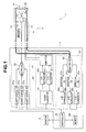
- Fig. 1 is a diagram illustrating a configuration of a main part of a scanning endoscope system according to the embodiment.
- a scanning endoscope system 1 includes, for example, as illustrated in Fig. 1 , a scanning endoscope 2 to be inserted into a body cavity of a subject, a body apparatus 3 to be connected to the scanning endoscope 2 and a monitor 4 to be connected to the body apparatus 3.
- the scanning endoscope 2 includes an insertion portion 11 formed so as to have an elongated shape and flexibility that enable the insertion portion 11 to be inserted into a body cavity of a subject. Note that in a proximal end portion of the insertion portion 11, e.g., a non-illustrated connector for detachably connecting the scanning endoscope 2 to the body apparatus 3 is provided.
- an illumination fiber 12 having a function as a light-guiding section that guides illuminating light supplied from a light source unit 21 of the body apparatus 3 to a light collection optical system 14, and light-reception fibers 13 that receive return light from an object and guide the return light to a detection unit 23 of the body apparatus 3 are inserted, respectively.
- An end portion of the illumination fiber 12 that includes a light entrance surface is disposed in a multiplexer 32 provided inside the body apparatus 3. Also, an end portion of the illumination fiber 12 that includes a light exit surface is disposed in the vicinity of a light entrance surface of a lens 14a provided in the distal end portion of the insertion portion 11 in such a manner that the end portion is not fixed via, e.g., a fixing member.
- each light-reception fiber 13 that includes a light entrance surface is fixedly disposed in the periphery of a light exit surface of a lens 14b in a distal end face of the distal end portion of the insertion portion 11. Also, an end portion of each light-reception fiber 13 that includes a light exit surface is disposed in a demultiplexer 36 provided inside the body apparatus 3.
- the light collection optical system 14 includes the lens 14a and the lens 14b, and is configured to collect illuminating light entered from the illumination fiber 12 and make the resulting illuminating light exit to the object.
- an actuator section 15 that is driven based on drive signals outputted from a driver unit 22 of the body apparatus 3 is provided.
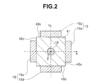
- the illumination fiber 12 and the actuator section 15 are each disposed so as to have, for example, the positional relationship illustrated in Fig. 2 in a cross-section perpendicular to a longitudinal axis direction of the insertion portion 11.
- Fig. 2 is a cross-sectional diagram for describing a configuration of the actuator section provided in the scanning endoscope.
- a ferrule 41 which serves as a joining member, is disposed between the illumination fiber 12 and the actuator section 15. More specifically, the ferrule 41 is formed of, for example, zirconia (ceramic) or nickel.
- the ferrule 41 is formed in the shape of a quadrangular prism, and includes side faces 42a and 42c perpendicular to an X-axis direction (transverse direction in the sheet) and side faces 42b and 42d perpendicular to a Y-axis direction (vertical direction in the sheet). Also, at a center of the ferrule 41, the illumination fiber 12 is fixedly disposed. Note that the ferrule 41 may be formed in another shape other than a quadrangular prism as long as such shape is a prism.
- the actuator section 15 includes an actuator 15a disposed along the side face 42a, an actuator 15b disposed along the side face 42b, an actuator 15c disposed along the side face 42c and an actuator 15d disposed along the side face 42d.
- the actuator section 15, which has a function as an optical scanning section, includes a pair of actuators 15a and 15c disposed at respective positions that face the Y-axis (or are symmetrical with respect to the Y-axis) across the illumination fiber 12, along the X-axis direction, and a pair of actuators 15b and 15d disposed at respective positions that face the X-axis (or are symmetrical with respect to the X-axis) across the illumination fiber 12, along the Y-axis direction.
- Each of the actuators 15a, 15b, 15c and 15d is configured to be driven according to a drive signal outputted from the driver unit 22.
- the actuator 15a includes, for example, a piezoelectric element subjected to polarization processing in advance so that a polarization direction thereof agrees with a negative direction of the X-axis (direction from the right to the left in the sheet of Fig.
- the actuator 15b includes, for example, a piezoelectric element subjected to polarization processing in advance so that a polarization direction thereof agrees with a negative direction of the Y-axis (direction from the top to the bottom in the sheet of Fig. 2 ), and is configured to, upon application of a voltage of a positive value according to a drive signal outputted from the driver unit 22, contract along the Z-axis direction, and upon application of a voltage of a negative value according to a drive signal outputted from the driver unit 22, expand along the Z-axis direction.
- the actuator 15c includes, for example, a piezoelectric element subjected to polarization processing in advance so that a polarization direction thereof agrees with the negative direction of the X-axis, and is configured to, upon application of a voltage of a negative value according to a drive signal outputted from the driver unit 22, contract along the Z-axis direction, and upon application of a voltage of a positive value according to a drive signal outputted from the driver unit 22, expand along the Z-axis direction.
- the actuator 15d includes, for example, a piezoelectric element subjected to polarization processing in advance so that a polarization direction thereof agrees with the negative direction of the Y-axis, and is configured to, upon application of a voltage of a negative value according to a drive signal outputted from the driver unit 22, contract in the Z-axis direction, and upon application of a voltage of a positive value according to a drive signal outputted from the driver unit 22, expand along the Z-axis direction.
- the actuator section 15 is not limited to one configured using the actuators 15a to 15d having such polarization directions and expansion/contraction directions as described above, and may be configured using actuators 15a to 15d having other polarization directions and expansion/contraction directions.
- the endoscope information stored in the memory 16 is read from a controller 25 in the body apparatus 3.
- the body apparatus 3 includes the light source unit 21, the driver unit 22, the detection unit 23, a memory 24 and the controller 25.
- the light source unit 21 includes a light source 31a, a light source 31b, a light source 31c and the multiplexer 32.
- the light source 31a includes, for example, a laser light source, and is configured to, when the light source 31a is controlled to be turned on by the controller 25, emit light of a red wavelength band (hereinafter also referred to as "R light") to the multiplexer 32.
- R light a red wavelength band
- the light source 31b includes, for example, a laser light source, and is configured to, when the light source 31b is controlled to be turned on by the controller 25, emit light of a green wavelength band (hereinafter also referred to as "G light") to the multiplexer 32.
- G light a green wavelength band
- the light source 31c includes, for example, a laser light source, and is configured to, when the light source 31c is controlled to be turned on by the controller 25, emit light of a blue wavelength band (hereinafter referred to as "B light") to the multiplexer 32.
- B light a blue wavelength band
- the multiplexer 32 is configured to combine the R light emitted from the light source 31a, the G light emitted from the light source 31b, and the B light emitted from the light source 31 c and supply the resulting light to the light entrance surface of the illumination fiber 12.
- the driver unit 22 has a function as a drive signal output section, and includes a signal generator 33, D/A converters 34a and 34b and an amplifier 35.
- the signal generator 33 is configured to generate respective drive signals for swinging the end portion of the illumination fiber 12 that includes the light exit surface, based on control performed by the controller 25, and output the respective drive signals to the D/A converters 34a and 34b.
- the D/A converters 34a and 34b are configured to convert the respective digital drive signals outputted from the signal generator 33 into analog drive signals and output the analog drive signals to the amplifier 35.
- the amplifier 35 is configured to amplify the respective drive signals outputted from the D/A converters 34a and 34b and output the resulting drive signals to the actuator section 15.
- the detection unit 23 includes the demultiplexer 36, detectors 37a, 37b and 37c, and A/D converters 38a, 38b and 38c.
- the demultiplexer 36 includes, e.g., a dichroic mirror, and is configured to split return light that has exited from the light exit surfaces of the light-reception fibers 13 into light of R (red) components, light of G (green) components and light of B (blue) components and make the light of R (red) components, the light of G (green) components and the light of B (blue) components exit to the respective detectors 37a, 37b and 37c.
- a dichroic mirror is configured to split return light that has exited from the light exit surfaces of the light-reception fibers 13 into light of R (red) components, light of G (green) components and light of B (blue) components and make the light of R (red) components, the light of G (green) components and the light of B (blue) components exit to the respective detectors 37a, 37b and 37c.
- the detector 37a is configured to detect an intensity of the R light outputted from the demultiplexer 36, generate an analog R signal according to the detected intensity of the R light and output the analog R signal to the A/D converter 38a.
- the detector 37b is configured to detect an intensity of the G light outputted from the demultiplexer 36, generate an analog G signal according the detected intensity of the G light and output the analog G signal to the A/D converter 38b.
- the detector 37c is configured to detect an intensity of the B light outputted from the demultiplexer 36, generate an analog B signal according to the detected intensity of the B light and output the analog B signal to the A/D converter 38c.
- the A/D converter 38a is configured to convert the analog R signal outputted from the detector 37a into a digital R signal and output the digital R signal to the controller 25.
- the A/D converter 38b is configured to convert the analog G signal outputted from the detector 37b into a digital G signal and output the digital G signal to the controller 25.
- the A/D converter 38c is configured to convert the analog B signal outputted from the detector 37c into a digital B signal and output the digital B signal to the controller 25.
- a control program for performing control of the body apparatus 3 is stored in advance. Also, in the memory 24, endoscope information read by the controller 25 in the body apparatus 3 is stored.
- the controller 25 includes, e.g., a CPU, and is configured to read the control program stored in the memory 24, and perform control of the light source unit 21 and the driver unit 22 based on the read control program.
- the actuator section 15, which has a function as an optical scanning section can swing the illumination fiber 12 so that positions in an object illuminated by illuminating light form a trajectory according to a predetermined scanning pattern, based on drive signals outputted from the driver unit 22 according to control performed by the controller 25 such as described above.
- the controller 25 operates so as to store the endoscope information outputted from the memory 16 when the insertion portion 11 is connected to the body apparatus 3, in the memory 24.
- the controller 25 is configured to generate an image based on the R signal, the G signal and the B signal outputted from the detection unit 23, and display the generated image on the monitor 4.
- the endoscope information stored in the memory 16 in the insertion portion 11 is read by the controller 25, and the read endoscope information is stored in the memory 24.
- the controller 25 stores the endoscope information read from the memory 16 in the memory 24, and then controls the light source unit 21 to switch the light sources 31a, 31b and 31c from “off” to “on”, and controls the driver unit 22 to output first and second drive signals, which will be described later, from the signal generator 33.
- the signal generator 33 Based on the control performed by the controller 25, the signal generator 33 generates a first drive signal having, for example, the waveform illustrated in Fig. 3 as a drive signal for driving the actuators 15a and 15b and outputs the first drive signal to the D/A converter 34a.
- Fig. 3 is a diagram illustrating an example of a waveform of the first drive signal used for driving the actuator section provided in the scanning endoscope.
- the signal generator 33 Based on the control performed by the controller 25, the signal generator 33 generates, for example, a sine wave having a voltage value periodically varying with a positive voltage value VP1 that is larger than zero as a center and having an amplitude value (peak value) that does not exceed (does not fall below) a negative voltage value VN1 corresponding to a coercive electric field in each of the actuators 15a and 15b, as a first drive signal (see Fig. 3 ).
- the signal generator 33 generates a second drive signal having, for example, the waveform illustrated in Fig. 4 as a drive signal for driving the actuators 15c and 15d and outputs the second drive signal to the D/A converter 34b.
- Fig. 4 is a diagram illustrating an example of a waveform of the second drive signal used for driving the actuator section provided in the scanning endoscope.
- the signal generator 33 Based on the control performed by the controller 25, the signal generator 33 generates, for example, a sine wave having a voltage value periodically varying with a negative voltage value VN2 that is smaller than zero as a center and having an amplitude value (peak value) that does not exceed (is not larger than) a positive voltage value VP2 corresponding to a coercive electric field in each of the actuators 15c and 15d, as a second drive signal (see Fig. 4 ).
- the aforementioned negative voltage value VN1 is a value determined according to a thickness in the polarization direction of the piezoelectric element in each of the actuators 15a and 15b.
- the aforementioned positive voltage value VP2 is a value determined according to a thickness in the polarization direction of the piezoelectric element in each of the actuators 15c and 15d.
- the first drive signal generated by the signal generator 33 is outputted to the actuators 15a and 15b through the D/A converter 34a and the amplifier 35.
- the second drive signal generated by the signal generator 33 is outputted to the actuators 15c and 15d through the D/A converter 34b and the amplifier 35.
- the illumination fiber 12 can be swung while a position in the X-axis direction of the ferrule 41 in a case where no voltage is applied to either of the actuators 15a and 15c (where neither of the actuators 15a and 15c expands/contracts) is maintained.
- the illumination fiber 12 can be swung while a position in the Y-axis direction of the ferrule 41 in a case where no voltage is applied to either of the actuators 15b and 15d (where neither of the actuators 15b and 15d expands/contracts) is maintained.
- the illumination fiber 12 is swung by means of a conventional method in which, for example, an alternating-current voltage according to a drive signal whose voltage value periodically varies with a voltage value of zero as a center is applied to each of the actuators 15a to 15d
- the alternating-current voltage according to the first drive signal whose voltage value periodically varies with the positive voltage value VP1 as a center is applied to the actuators 15a and 15b and the alternating-current voltage according to the second drive signal whose voltage value periodically varies with the negative voltage value VN2 as a center is applied to the actuators 15c and 15d, thereby relaxing the limitations on the amplitude value (peak value) by the negative voltage value VN1 and the positive voltage value VP2.
- the present embodiment enables the illumination fiber 12 to be swung in a wide area compared to the conventional method, that is, enables a scanning area of an object to be widened compared to the conventional method.
Landscapes
- Health & Medical Sciences (AREA)
- Life Sciences & Earth Sciences (AREA)
- Physics & Mathematics (AREA)
- Surgery (AREA)
- Optics & Photonics (AREA)
- Biomedical Technology (AREA)
- Animal Behavior & Ethology (AREA)
- Radiology & Medical Imaging (AREA)
- Nuclear Medicine, Radiotherapy & Molecular Imaging (AREA)
- Engineering & Computer Science (AREA)
- Biophysics (AREA)
- Heart & Thoracic Surgery (AREA)
- Medical Informatics (AREA)
- Molecular Biology (AREA)
- Pathology (AREA)
- General Health & Medical Sciences (AREA)
- Public Health (AREA)
- Veterinary Medicine (AREA)
- General Physics & Mathematics (AREA)
- Astronomy & Astrophysics (AREA)
- Endoscopes (AREA)
- Instruments For Viewing The Inside Of Hollow Bodies (AREA)
Abstract
Description
- The present invention relates to a scanning endoscope system, and specifically relates to a scanning endoscope system for scanning an object to obtain an image.
- In endoscopes in a medical field, in order to reduce a burden on subjects, various techniques for thinning insertion portions to be inserted into body cavities of the subjects have been proposed. As an example of such techniques, a scanning endoscope including no solid image pickup device in a part corresponding to the aforementioned insertion portion and a system including the scanning endoscope are known.
- More specifically, the system including the scanning endoscope is configured to, for example, swing a distal end portion of an illumination fiber that guides illuminating light emitted from a light source section to two-dimensionally scan an object according to a pre-set scanning pattern, receive return light from the object via light-reception fibers disposed in the periphery of the illumination fiber and generate an image of the object based on the return light received via the light-reception fibers. As an example of those having a configuration similar to such system, the scanning beam system disclosed in
U.S. Patent Application Publication No. 2008/0218824 is known. - Incidentally, in the conventional scanning endoscope as described above, it is configured such that the illumination fiber is swung by applying, to an actuator configured to include a piezoelectric element subjected to polarization processing in advance, a voltage not exceeding magnitude of a coercive electric field in accordance with a thickness of the piezoelectric element in a polarization direction.
- However, when configuring the scanning endoscope using the above-mentioned actuator, it is necessary to make thickness of the piezoelectric element in the polarization direction as thin as possible so as to realize reduction of a diameter of the insertion portion. On the other hand, in the above-mentioned actuator, there is a problem that a relatively strict restriction is imposed on a limit value of an applied voltage necessary for maintaining the polarization of the piezoelectric element, due to decrease of the magnitude of the coercive electric field in accordance with decrease of the thickness of the piezoelectric element in the polarization direction.
- In contrast, in
U.S. Patent Application Publication No. 2008/0218824 , there is not any particular reference to a method or the like that is capable of solving the foregoing problem. Therefore, according to the configuration disclosed inU.S. Patent Application Publication No. 2008/0218824 , there arises a problem, for example, that it is impossible to broaden a scanning range of the object by the scanning endoscope to be not less than a predetermined region. - The present invention has been made in view of the foregoing circumstances and an object of the present invention is to provide a scanning endoscope capable of broadening a scanning range of a subject as compared with a conventional one.
- A scanning endoscope system according to an aspect of the present invention includes: a light-guiding section that guides illuminating light emitted from a light source; an optical scanning section that includes at least one pair of driving sections arranged at positions to face each other across the light-guiding section, and is capable of swinging the light-guiding section so that a position in an object illuminated by the illuminating light forms a trajectory according to a predetermined scanning pattern by driving the driving sections; and a drive signal outputting section configured to output a first drive signal which has a waveform with a predetermined positive voltage value as a center to one driving section in the at least one pair of driving sections which are arranged along a predetermined axial direction in the optical scanning section, and to output a second drive signal which has a waveform with a predetermined negative voltage value as a center to other driving section in the at least one pair of driving sections.
-
-
Fig. 1 is a diagram illustrating a configuration of a main part of a scanning endoscope system according to an embodiment; -
Fig. 2 is a cross-sectional diagram for describing a configuration of an actuator section provided in the scanning endoscope; -
Fig. 3 is a diagram illustrating an example of a waveform of a first drive signal, which is used for driving the actuator section provided in the scanning endoscope; and -
Fig. 4 is a diagram illustrating an example of a waveform of a second drive signal, which is used for driving the actuator section provided in the scanning endoscope. - An embodiment of the present invention will be described below with reference to the drawings.
-
Figs. 1 to 4 relate to an embodiment of the present invention.Fig. 1 is a diagram illustrating a configuration of a main part of a scanning endoscope system according to the embodiment. - A scanning endoscope system 1 includes, for example, as illustrated in
Fig. 1 , ascanning endoscope 2 to be inserted into a body cavity of a subject, abody apparatus 3 to be connected to thescanning endoscope 2 and amonitor 4 to be connected to thebody apparatus 3. - The
scanning endoscope 2 includes aninsertion portion 11 formed so as to have an elongated shape and flexibility that enable theinsertion portion 11 to be inserted into a body cavity of a subject. Note that in a proximal end portion of theinsertion portion 11, e.g., a non-illustrated connector for detachably connecting thescanning endoscope 2 to thebody apparatus 3 is provided. - In a part from the proximal end portion to a distal end portion of the inside of the
insertion portion 11, anillumination fiber 12 having a function as a light-guiding section that guides illuminating light supplied from alight source unit 21 of thebody apparatus 3 to a light collectionoptical system 14, and light-reception fibers 13 that receive return light from an object and guide the return light to adetection unit 23 of thebody apparatus 3 are inserted, respectively. - An end portion of the
illumination fiber 12 that includes a light entrance surface is disposed in amultiplexer 32 provided inside thebody apparatus 3. Also, an end portion of theillumination fiber 12 that includes a light exit surface is disposed in the vicinity of a light entrance surface of alens 14a provided in the distal end portion of theinsertion portion 11 in such a manner that the end portion is not fixed via, e.g., a fixing member. - An end portion of each light-
reception fiber 13 that includes a light entrance surface is fixedly disposed in the periphery of a light exit surface of alens 14b in a distal end face of the distal end portion of theinsertion portion 11. Also, an end portion of each light-reception fiber 13 that includes a light exit surface is disposed in ademultiplexer 36 provided inside thebody apparatus 3. - The light collection
optical system 14 includes thelens 14a and thelens 14b, and is configured to collect illuminating light entered from theillumination fiber 12 and make the resulting illuminating light exit to the object. - In a portion partway of the
illumination fiber 12 on the distal end portion side of theinsertion portion 11, anactuator section 15 that is driven based on drive signals outputted from adriver unit 22 of thebody apparatus 3 is provided. - The
illumination fiber 12 and theactuator section 15 are each disposed so as to have, for example, the positional relationship illustrated inFig. 2 in a cross-section perpendicular to a longitudinal axis direction of theinsertion portion 11.Fig. 2 is a cross-sectional diagram for describing a configuration of the actuator section provided in the scanning endoscope. - As illustrated in
Fig. 2 , aferrule 41, which serves as a joining member, is disposed between theillumination fiber 12 and theactuator section 15. More specifically, theferrule 41 is formed of, for example, zirconia (ceramic) or nickel. - As illustrated in
Fig. 2 , theferrule 41 is formed in the shape of a quadrangular prism, and includesside faces side faces ferrule 41, theillumination fiber 12 is fixedly disposed. Note that theferrule 41 may be formed in another shape other than a quadrangular prism as long as such shape is a prism. - As illustrated in
Fig. 2 , theactuator section 15 includes anactuator 15a disposed along theside face 42a, anactuator 15b disposed along theside face 42b, anactuator 15c disposed along theside face 42c and anactuator 15d disposed along theside face 42d. - In other words, the
actuator section 15, which has a function as an optical scanning section, includes a pair ofactuators illumination fiber 12, along the X-axis direction, and a pair ofactuators illumination fiber 12, along the Y-axis direction. - Each of the
actuators driver unit 22. - The
actuator 15a includes, for example, a piezoelectric element subjected to polarization processing in advance so that a polarization direction thereof agrees with a negative direction of the X-axis (direction from the right to the left in the sheet ofFig. 2 ), and is configured to, upon application of a voltage of a positive value according to a drive signal outputted from the driver unit 22 (if a direction of an electric field generated as a result of supply of the drive signal is a forward direction relative to the polarization direction), contract along a Z-axis direction (normal direction in the sheet), and upon application of a voltage of a negative value according to a drive signal outputted from the driver unit 22 (if a direction of an electric field generated as a result of supply of the drive signal is a backward direction relative to the polarization direction), expand along the Z-axis direction. - The
actuator 15b includes, for example, a piezoelectric element subjected to polarization processing in advance so that a polarization direction thereof agrees with a negative direction of the Y-axis (direction from the top to the bottom in the sheet ofFig. 2 ), and is configured to, upon application of a voltage of a positive value according to a drive signal outputted from thedriver unit 22, contract along the Z-axis direction, and upon application of a voltage of a negative value according to a drive signal outputted from thedriver unit 22, expand along the Z-axis direction. - The
actuator 15c includes, for example, a piezoelectric element subjected to polarization processing in advance so that a polarization direction thereof agrees with the negative direction of the X-axis, and is configured to, upon application of a voltage of a negative value according to a drive signal outputted from thedriver unit 22, contract along the Z-axis direction, and upon application of a voltage of a positive value according to a drive signal outputted from thedriver unit 22, expand along the Z-axis direction. - The
actuator 15d includes, for example, a piezoelectric element subjected to polarization processing in advance so that a polarization direction thereof agrees with the negative direction of the Y-axis, and is configured to, upon application of a voltage of a negative value according to a drive signal outputted from thedriver unit 22, contract in the Z-axis direction, and upon application of a voltage of a positive value according to a drive signal outputted from thedriver unit 22, expand along the Z-axis direction. - Note that according to the present embodiment, the
actuator section 15 is not limited to one configured using theactuators 15a to 15d having such polarization directions and expansion/contraction directions as described above, and may be configured usingactuators 15a to 15d having other polarization directions and expansion/contraction directions. - Inside the
insertion portion 11, amemory 16 with endoscope information stored in advance, the endoscope information including various pieces of information such as individual identification information for thescanning endoscope 2, is provided. Upon thescanning endoscope 2 and thebody apparatus 3 being connected, the endoscope information stored in thememory 16 is read from acontroller 25 in thebody apparatus 3. - The
body apparatus 3 includes thelight source unit 21, thedriver unit 22, thedetection unit 23, amemory 24 and thecontroller 25. - The
light source unit 21 includes alight source 31a, alight source 31b, alight source 31c and themultiplexer 32. - The
light source 31a includes, for example, a laser light source, and is configured to, when thelight source 31a is controlled to be turned on by thecontroller 25, emit light of a red wavelength band (hereinafter also referred to as "R light") to themultiplexer 32. - The
light source 31b includes, for example, a laser light source, and is configured to, when thelight source 31b is controlled to be turned on by thecontroller 25, emit light of a green wavelength band (hereinafter also referred to as "G light") to themultiplexer 32. - The
light source 31c includes, for example, a laser light source, and is configured to, when thelight source 31c is controlled to be turned on by thecontroller 25, emit light of a blue wavelength band (hereinafter referred to as "B light") to themultiplexer 32. - The
multiplexer 32 is configured to combine the R light emitted from thelight source 31a, the G light emitted from thelight source 31b, and the B light emitted from thelight source 31 c and supply the resulting light to the light entrance surface of theillumination fiber 12. - The
driver unit 22 has a function as a drive signal output section, and includes asignal generator 33, D/A converters amplifier 35. - The
signal generator 33 is configured to generate respective drive signals for swinging the end portion of theillumination fiber 12 that includes the light exit surface, based on control performed by thecontroller 25, and output the respective drive signals to the D/A converters - The D/
A converters signal generator 33 into analog drive signals and output the analog drive signals to theamplifier 35. - The
amplifier 35 is configured to amplify the respective drive signals outputted from the D/A converters actuator section 15. - The
detection unit 23 includes thedemultiplexer 36,detectors D converters - The
demultiplexer 36 includes, e.g., a dichroic mirror, and is configured to split return light that has exited from the light exit surfaces of the light-reception fibers 13 into light of R (red) components, light of G (green) components and light of B (blue) components and make the light of R (red) components, the light of G (green) components and the light of B (blue) components exit to therespective detectors - The
detector 37a is configured to detect an intensity of the R light outputted from thedemultiplexer 36, generate an analog R signal according to the detected intensity of the R light and output the analog R signal to the A/D converter 38a. - The
detector 37b is configured to detect an intensity of the G light outputted from thedemultiplexer 36, generate an analog G signal according the detected intensity of the G light and output the analog G signal to the A/D converter 38b. - The
detector 37c is configured to detect an intensity of the B light outputted from thedemultiplexer 36, generate an analog B signal according to the detected intensity of the B light and output the analog B signal to the A/D converter 38c. - The A/
D converter 38a is configured to convert the analog R signal outputted from thedetector 37a into a digital R signal and output the digital R signal to thecontroller 25. - The A/
D converter 38b is configured to convert the analog G signal outputted from thedetector 37b into a digital G signal and output the digital G signal to thecontroller 25. - The A/
D converter 38c is configured to convert the analog B signal outputted from thedetector 37c into a digital B signal and output the digital B signal to thecontroller 25. - In the
memory 24, e.g., a control program for performing control of thebody apparatus 3 is stored in advance. Also, in thememory 24, endoscope information read by thecontroller 25 in thebody apparatus 3 is stored. - The
controller 25 includes, e.g., a CPU, and is configured to read the control program stored in thememory 24, and perform control of thelight source unit 21 and thedriver unit 22 based on the read control program. In other words, theactuator section 15, which has a function as an optical scanning section, can swing theillumination fiber 12 so that positions in an object illuminated by illuminating light form a trajectory according to a predetermined scanning pattern, based on drive signals outputted from thedriver unit 22 according to control performed by thecontroller 25 such as described above. - The
controller 25 operates so as to store the endoscope information outputted from thememory 16 when theinsertion portion 11 is connected to thebody apparatus 3, in thememory 24. - The
controller 25 is configured to generate an image based on the R signal, the G signal and the B signal outputted from thedetection unit 23, and display the generated image on themonitor 4. - Next, an operation, etc., of the scanning endoscope system 1 having the above described configuration will be described.
- When power sources of the respective components of the scanning endoscope system 1 are turned on, the endoscope information stored in the
memory 16 in theinsertion portion 11 is read by thecontroller 25, and the read endoscope information is stored in thememory 24. - The
controller 25 stores the endoscope information read from thememory 16 in thememory 24, and then controls thelight source unit 21 to switch thelight sources driver unit 22 to output first and second drive signals, which will be described later, from thesignal generator 33. - Based on the control performed by the
controller 25, thesignal generator 33 generates a first drive signal having, for example, the waveform illustrated inFig. 3 as a drive signal for driving theactuators A converter 34a.Fig. 3 is a diagram illustrating an example of a waveform of the first drive signal used for driving the actuator section provided in the scanning endoscope. - More specifically, based on the control performed by the
controller 25, thesignal generator 33 generates, for example, a sine wave having a voltage value periodically varying with a positive voltage value VP1 that is larger than zero as a center and having an amplitude value (peak value) that does not exceed (does not fall below) a negative voltage value VN1 corresponding to a coercive electric field in each of theactuators Fig. 3 ). - Also, based on the control performed by the
controller 25, thesignal generator 33 generates a second drive signal having, for example, the waveform illustrated inFig. 4 as a drive signal for driving theactuators A converter 34b.Fig. 4 is a diagram illustrating an example of a waveform of the second drive signal used for driving the actuator section provided in the scanning endoscope. - More specifically, based on the control performed by the
controller 25, thesignal generator 33 generates, for example, a sine wave having a voltage value periodically varying with a negative voltage value VN2 that is smaller than zero as a center and having an amplitude value (peak value) that does not exceed (is not larger than) a positive voltage value VP2 corresponding to a coercive electric field in each of theactuators Fig. 4 ). - Note that the aforementioned negative voltage value VN1 is a value determined according to a thickness in the polarization direction of the piezoelectric element in each of the
actuators actuators actuators 15a to 15d are formed by respective piezoelectric elements having a same thickness in the respective polarization directions, a relationship of VN1 = -VP2 holds between the negative voltage value VN1 and the positive voltage value VP2. - The above-described first and second drive signals are generated so as to have a same phase and provide the relationship of VP1 = -VN2 in order to balance among forces applied to the
ferrule 41 as a result of driving of theactuators 15a to 15d. - Then, the first drive signal generated by the
signal generator 33 is outputted to theactuators A converter 34a and theamplifier 35. Also, the second drive signal generated by thesignal generator 33 is outputted to theactuators A converter 34b and theamplifier 35. - Here, where an alternating-current voltage according to the above-described first drive signal is applied to the
actuator 15a, and an alternating-current voltage according to the above-described second drive signal is applied to theactuator 15c, a force applied to theferrule 41 as a result of expansion/contraction of theactuator 15a and a force applied to theferrule 41 as a result of expansion/contraction of the actuator 15c are cancelled out. Thus, as a result of the alternating-current voltage according to the first drive signal being applied to theactuator 15a and the alternating-current voltage according to the second drive signal being applied to theactuator 15c, theillumination fiber 12 can be swung while a position in the X-axis direction of theferrule 41 in a case where no voltage is applied to either of theactuators actuators - Also, where the alternating-current voltage according to the first drive signal is applied to the
actuator 15b and the alternating-current voltage according to the second drive signal is applied to theactuator 15d, a force applied to theferrule 41 as a result of expansion/contraction of theactuator 15b and a force applied to theferrule 41 as a result of expansion/contraction of theactuator 15d are cancelled out. Thus, as a result of the alternating-current voltage according to the first drive signal being applied to theactuator 15b and the alternating-current voltage according to the second drive signal being applied to theactuator 15d, theillumination fiber 12 can be swung while a position in the Y-axis direction of theferrule 41 in a case where no voltage is applied to either of theactuators actuators - In a case where the
illumination fiber 12 is swung by means of a conventional method in which, for example, an alternating-current voltage according to a drive signal whose voltage value periodically varies with a voltage value of zero as a center is applied to each of theactuators 15a to 15d, there is substantially no need to take balancing of forces applied to theferrule 41 into account; however, in order to maintain polarization of theactuators 15a to 15d, there is a need to set an amplitude value within a range between the negative voltage value VN1 corresponding to a coercive electric field in each of theactuators actuators - On the other hand, according to the present embodiment, the alternating-current voltage according to the first drive signal whose voltage value periodically varies with the positive voltage value VP1 as a center is applied to the
actuators actuators illumination fiber 12 to be swung in a wide area compared to the conventional method, that is, enables a scanning area of an object to be widened compared to the conventional method. - It should be understood that the present invention is not limited to the above-described embodiment, and various modifications and applications are possible without departing from the spirit of the invention.
- The present application is filed claiming the priority of Japanese Patent Application No.
2012-233024
Claims (5)
- A scanning endoscope system comprising:a light-guiding section that guides illuminating light emitted from a light source;an optical scanning section that includes at least one pair of driving sections arranged at positions to face each other across the light-guiding section, and is capable of swinging the light-guiding section so that a position in an object illuminated by the illuminating light forms a trajectory according to a predetermined scanning pattern by driving the driving sections; anda drive signal outputting section configured to output a first drive signal which has a waveform with a predetermined positive voltage value as a center to one driving section in the at least one pair of driving sections which are arranged along a predetermined axial direction in the optical scanning section, and to output a second drive signal which has a waveform with a predetermined negative voltage value as a center to other driving section in the at least one pair of driving sections.
- The scanning endoscope system according to claim 1,
wherein each of the one driving section and the other driving section includes a piezoelectric element; and
wherein each of an amplitude value of the first drive signal and an amplitude value of the second drive signal is set so as not to exceed a voltage value corresponding to a coercive electric field in the respective piezoelectric elements. - The scanning endoscope system according to claim 2, wherein the respective piezoelectric elements included in the one driving section and the other driving section are subjected to polarization processing in advance so as to have a same polarization direction along the predetermined axis direction and formed so as to have a same thickness in the polarization direction.
- The scanning endoscope system according to claim 1,
wherein the first drive signal and the second drive signal have a same phase; and
wherein a value resulting from positive/negative reversal of a voltage value of one of the predetermined positive voltage value and the predetermined negative voltage value is equal to a voltage value of the other of the predetermined positive voltage value and the predetermined negative voltage value. - The scanning endoscope system according to claim 1 further comprising:a light-receiving section that receives return light of the illuminating light applied to the object;a light-detecting section configured to generate a signal according to an intensity of the return light received by the light-receiving section and output the signal; andan image-generating section configured to generate an image of the object based on the signal outputted from the light-detecting section.
Applications Claiming Priority (2)
| Application Number | Priority Date | Filing Date | Title |
|---|---|---|---|
| JP2012233024 | 2012-10-22 | ||
| PCT/JP2013/074102 WO2014065025A1 (en) | 2012-10-22 | 2013-09-06 | Scanning endoscope system |
Publications (3)
| Publication Number | Publication Date |
|---|---|
| EP2848188A1 true EP2848188A1 (en) | 2015-03-18 |
| EP2848188A4 EP2848188A4 (en) | 2016-03-02 |
| EP2848188B1 EP2848188B1 (en) | 2019-01-30 |
Family
ID=50544406
Family Applications (1)
| Application Number | Title | Priority Date | Filing Date |
|---|---|---|---|
| EP13849728.4A Not-in-force EP2848188B1 (en) | 2012-10-22 | 2013-09-06 | Scanning endoscope system |
Country Status (5)
| Country | Link |
|---|---|
| US (1) | US9629517B2 (en) |
| EP (1) | EP2848188B1 (en) |
| JP (1) | JP5639310B2 (en) |
| CN (1) | CN104363816B (en) |
| WO (1) | WO2014065025A1 (en) |
Families Citing this family (10)
| Publication number | Priority date | Publication date | Assignee | Title |
|---|---|---|---|---|
| JP6438221B2 (en) * | 2014-06-25 | 2018-12-12 | オリンパス株式会社 | Optical scanning actuator and optical scanning device |
| DE112015006046T5 (en) * | 2015-03-12 | 2017-11-23 | Olympus Corporation | Scanning endoscope system |
| WO2016151627A1 (en) * | 2015-03-24 | 2016-09-29 | オリンパス株式会社 | Scanning-type observation device and image display method of scanning-type observation device |
| JP6522748B2 (en) * | 2015-05-22 | 2019-05-29 | オリンパス株式会社 | Scanning endoscope and control method thereof |
| JPWO2016189627A1 (en) * | 2015-05-25 | 2018-03-08 | オリンパス株式会社 | Optical fiber scanner, illumination device and observation device |
| WO2017029691A1 (en) * | 2015-08-18 | 2017-02-23 | オリンパス株式会社 | Optical scanning method, optical scanning device, and optical scanning observation device |
| EP3451084B1 (en) | 2017-08-29 | 2021-10-20 | Honda Research Institute Europe GmbH | Method for setting parameters in an autonomous working device |
| CN108803006B (en) * | 2017-09-18 | 2021-01-05 | 成都理想境界科技有限公司 | Optical fiber scanning imaging system, optical fiber scanning imaging equipment and distortion detection and correction system of optical fiber scanning imaging equipment |
| US20210033850A1 (en) * | 2018-02-09 | 2021-02-04 | Chengdu Idealsee Technology Co., Ltd. | Optical fiber scanner, optical fiber scanning device and optical fiber scanning apparatus |
| CN108803012A (en) * | 2018-03-26 | 2018-11-13 | 成都理想境界科技有限公司 | Method and fibre optic scanner in optical fiber scanning for correcting image distortion |
Family Cites Families (10)
| Publication number | Priority date | Publication date | Assignee | Title |
|---|---|---|---|---|
| JP2001174744A (en) * | 1999-10-06 | 2001-06-29 | Olympus Optical Co Ltd | Optical scanning probe device |
| US7784697B2 (en) | 2004-12-23 | 2010-08-31 | University Of Washington | Methods of driving a scanning beam device to achieve high frame rates |
| JP2009516568A (en) * | 2005-11-23 | 2009-04-23 | ユニヴァーシティ オブ ワシントン | Scanning a beam with variable sequential framing using interrupted scanning resonances |
| US7608842B2 (en) | 2007-04-26 | 2009-10-27 | University Of Washington | Driving scanning fiber devices with variable frequency drive signals |
| JP2009207584A (en) * | 2008-03-03 | 2009-09-17 | Hoya Corp | Endoscope system |
| JP5235650B2 (en) * | 2008-12-26 | 2013-07-10 | Hoya株式会社 | Optical scanning endoscope apparatus, optical scanning endoscope, and optical scanning endoscope processor |
| US8348829B2 (en) * | 2008-12-26 | 2013-01-08 | Hoya Corporation | Scanning endoscope apparatus, scanning endoscope, and scanning endoscope processor |
| JP2011115252A (en) * | 2009-12-01 | 2011-06-16 | Hoya Corp | Medical probe and medical observation system |
| JP5721406B2 (en) * | 2010-11-24 | 2015-05-20 | Hoya株式会社 | Scanning confocal endoscope system |
| JP2012152244A (en) * | 2011-01-21 | 2012-08-16 | Hoya Corp | Optical fiber scanning device |
-
2013
- 2013-09-06 JP JP2014517297A patent/JP5639310B2/en active Active
- 2013-09-06 WO PCT/JP2013/074102 patent/WO2014065025A1/en not_active Ceased
- 2013-09-06 EP EP13849728.4A patent/EP2848188B1/en not_active Not-in-force
- 2013-09-06 CN CN201380031803.7A patent/CN104363816B/en not_active Expired - Fee Related
-
2014
- 2014-05-05 US US14/269,297 patent/US9629517B2/en active Active
Also Published As
| Publication number | Publication date |
|---|---|
| CN104363816A (en) | 2015-02-18 |
| CN104363816B (en) | 2017-05-24 |
| US20150038786A1 (en) | 2015-02-05 |
| US9629517B2 (en) | 2017-04-25 |
| EP2848188A4 (en) | 2016-03-02 |
| JP5639310B2 (en) | 2014-12-10 |
| WO2014065025A1 (en) | 2014-05-01 |
| EP2848188B1 (en) | 2019-01-30 |
| JPWO2014065025A1 (en) | 2016-09-08 |
Similar Documents
| Publication | Publication Date | Title |
|---|---|---|
| EP2848188B1 (en) | Scanning endoscope system | |
| EP2896351B1 (en) | Scanning endoscope system, and method for operating scanning endoscope system | |
| EP2742848A1 (en) | Endoscope and endoscope device | |
| EP2946717A1 (en) | Scanning endoscope | |
| US9179830B2 (en) | Scanning endoscope apparatus | |
| EP2789289B1 (en) | Endoscope device and treatment device | |
| US20170090181A1 (en) | Optical scanning endoscope apparatus | |
| WO2015163001A1 (en) | Optical scanning device and scanning-type endoscope | |
| US10609297B2 (en) | Optical scanning endoscope apparatus with light amount detector | |
| CN107430270A (en) | Scanning trajectory measurement method of optical scanning device, scanning trajectory measurement device, and image calibration method | |
| EP2989959A1 (en) | Scanning endoscope | |
| US20170065156A1 (en) | Scanning-type endoscope | |
| US9585544B2 (en) | Scanning endoscope system | |
| JPWO2016143160A1 (en) | Scanning endoscope system | |
| EP3114982A1 (en) | Optical scanning observation system | |
| WO2016017199A1 (en) | Optical scanning observation system | |
| JP6081678B1 (en) | Scanning endoscope | |
| CN107427182A (en) | The method for displaying image of sweep type observation device and sweep type observation device |
Legal Events
| Date | Code | Title | Description |
|---|---|---|---|
| PUAI | Public reference made under article 153(3) epc to a published international application that has entered the european phase |
Free format text: ORIGINAL CODE: 0009012 |
|
| 17P | Request for examination filed |
Effective date: 20141202 |
|
| AK | Designated contracting states |
Kind code of ref document: A1 Designated state(s): AL AT BE BG CH CY CZ DE DK EE ES FI FR GB GR HR HU IE IS IT LI LT LU LV MC MK MT NL NO PL PT RO RS SE SI SK SM TR |
|
| AX | Request for extension of the european patent |
Extension state: BA ME |
|
| RAP1 | Party data changed (applicant data changed or rights of an application transferred) |
Owner name: OLYMPUS CORPORATION |
|
| DAX | Request for extension of the european patent (deleted) | ||
| RA4 | Supplementary search report drawn up and despatched (corrected) |
Effective date: 20160129 |
|
| RIC1 | Information provided on ipc code assigned before grant |
Ipc: G02B 23/26 20060101ALI20160125BHEP Ipc: G02B 26/10 20060101ALI20160125BHEP Ipc: G02B 23/24 20060101ALI20160125BHEP Ipc: A61B 1/00 20060101AFI20160125BHEP |
|
| RAP1 | Party data changed (applicant data changed or rights of an application transferred) |
Owner name: OLYMPUS CORPORATION |
|
| RAP1 | Party data changed (applicant data changed or rights of an application transferred) |
Owner name: OLYMPUS CORPORATION |
|
| R17P | Request for examination filed (corrected) |
Effective date: 20141202 |
|
| RIN1 | Information on inventor provided before grant (corrected) |
Inventor name: OKITA, YOSHINARI Inventor name: SAKAI, YUJI |
|
| GRAP | Despatch of communication of intention to grant a patent |
Free format text: ORIGINAL CODE: EPIDOSNIGR1 |
|
| STAA | Information on the status of an ep patent application or granted ep patent |
Free format text: STATUS: GRANT OF PATENT IS INTENDED |
|
| RIC1 | Information provided on ipc code assigned before grant |
Ipc: G02B 23/24 20060101ALI20180810BHEP Ipc: A61B 1/07 20060101ALI20180810BHEP Ipc: G02B 23/26 20060101ALI20180810BHEP Ipc: A61B 1/00 20060101AFI20180810BHEP Ipc: G02B 26/10 20060101ALI20180810BHEP |
|
| INTG | Intention to grant announced |
Effective date: 20180829 |
|
| RIN1 | Information on inventor provided before grant (corrected) |
Inventor name: OKITA, YOSHINARI Inventor name: SAKAI, YUJI |
|
| GRAS | Grant fee paid |
Free format text: ORIGINAL CODE: EPIDOSNIGR3 |
|
| GRAA | (expected) grant |
Free format text: ORIGINAL CODE: 0009210 |
|
| STAA | Information on the status of an ep patent application or granted ep patent |
Free format text: STATUS: THE PATENT HAS BEEN GRANTED |
|
| AK | Designated contracting states |
Kind code of ref document: B1 Designated state(s): AL AT BE BG CH CY CZ DE DK EE ES FI FR GB GR HR HU IE IS IT LI LT LU LV MC MK MT NL NO PL PT RO RS SE SI SK SM TR |
|
| REG | Reference to a national code |
Ref country code: GB Ref legal event code: FG4D |
|
| REG | Reference to a national code |
Ref country code: CH Ref legal event code: EP |
|
| REG | Reference to a national code |
Ref country code: AT Ref legal event code: REF Ref document number: 1092576 Country of ref document: AT Kind code of ref document: T Effective date: 20190215 |
|
| REG | Reference to a national code |
Ref country code: IE Ref legal event code: FG4D |
|
| REG | Reference to a national code |
Ref country code: DE Ref legal event code: R096 Ref document number: 602013050357 Country of ref document: DE |
|
| REG | Reference to a national code |
Ref country code: LT Ref legal event code: MG4D |
|
| REG | Reference to a national code |
Ref country code: NL Ref legal event code: MP Effective date: 20190130 |
|
| PG25 | Lapsed in a contracting state [announced via postgrant information from national office to epo] |
Ref country code: NO Free format text: LAPSE BECAUSE OF FAILURE TO SUBMIT A TRANSLATION OF THE DESCRIPTION OR TO PAY THE FEE WITHIN THE PRESCRIBED TIME-LIMIT Effective date: 20190430 Ref country code: PT Free format text: LAPSE BECAUSE OF FAILURE TO SUBMIT A TRANSLATION OF THE DESCRIPTION OR TO PAY THE FEE WITHIN THE PRESCRIBED TIME-LIMIT Effective date: 20190530 Ref country code: SE Free format text: LAPSE BECAUSE OF FAILURE TO SUBMIT A TRANSLATION OF THE DESCRIPTION OR TO PAY THE FEE WITHIN THE PRESCRIBED TIME-LIMIT Effective date: 20190130 Ref country code: FI Free format text: LAPSE BECAUSE OF FAILURE TO SUBMIT A TRANSLATION OF THE DESCRIPTION OR TO PAY THE FEE WITHIN THE PRESCRIBED TIME-LIMIT Effective date: 20190130 Ref country code: LT Free format text: LAPSE BECAUSE OF FAILURE TO SUBMIT A TRANSLATION OF THE DESCRIPTION OR TO PAY THE FEE WITHIN THE PRESCRIBED TIME-LIMIT Effective date: 20190130 Ref country code: PL Free format text: LAPSE BECAUSE OF FAILURE TO SUBMIT A TRANSLATION OF THE DESCRIPTION OR TO PAY THE FEE WITHIN THE PRESCRIBED TIME-LIMIT Effective date: 20190130 Ref country code: ES Free format text: LAPSE BECAUSE OF FAILURE TO SUBMIT A TRANSLATION OF THE DESCRIPTION OR TO PAY THE FEE WITHIN THE PRESCRIBED TIME-LIMIT Effective date: 20190130 Ref country code: NL Free format text: LAPSE BECAUSE OF FAILURE TO SUBMIT A TRANSLATION OF THE DESCRIPTION OR TO PAY THE FEE WITHIN THE PRESCRIBED TIME-LIMIT Effective date: 20190130 |
|
| REG | Reference to a national code |
Ref country code: AT Ref legal event code: MK05 Ref document number: 1092576 Country of ref document: AT Kind code of ref document: T Effective date: 20190130 |
|
| PG25 | Lapsed in a contracting state [announced via postgrant information from national office to epo] |
Ref country code: HR Free format text: LAPSE BECAUSE OF FAILURE TO SUBMIT A TRANSLATION OF THE DESCRIPTION OR TO PAY THE FEE WITHIN THE PRESCRIBED TIME-LIMIT Effective date: 20190130 Ref country code: GR Free format text: LAPSE BECAUSE OF FAILURE TO SUBMIT A TRANSLATION OF THE DESCRIPTION OR TO PAY THE FEE WITHIN THE PRESCRIBED TIME-LIMIT Effective date: 20190501 Ref country code: LV Free format text: LAPSE BECAUSE OF FAILURE TO SUBMIT A TRANSLATION OF THE DESCRIPTION OR TO PAY THE FEE WITHIN THE PRESCRIBED TIME-LIMIT Effective date: 20190130 Ref country code: IS Free format text: LAPSE BECAUSE OF FAILURE TO SUBMIT A TRANSLATION OF THE DESCRIPTION OR TO PAY THE FEE WITHIN THE PRESCRIBED TIME-LIMIT Effective date: 20190530 Ref country code: BG Free format text: LAPSE BECAUSE OF FAILURE TO SUBMIT A TRANSLATION OF THE DESCRIPTION OR TO PAY THE FEE WITHIN THE PRESCRIBED TIME-LIMIT Effective date: 20190430 Ref country code: RS Free format text: LAPSE BECAUSE OF FAILURE TO SUBMIT A TRANSLATION OF THE DESCRIPTION OR TO PAY THE FEE WITHIN THE PRESCRIBED TIME-LIMIT Effective date: 20190130 |
|
| PG25 | Lapsed in a contracting state [announced via postgrant information from national office to epo] |
Ref country code: SK Free format text: LAPSE BECAUSE OF FAILURE TO SUBMIT A TRANSLATION OF THE DESCRIPTION OR TO PAY THE FEE WITHIN THE PRESCRIBED TIME-LIMIT Effective date: 20190130 Ref country code: DK Free format text: LAPSE BECAUSE OF FAILURE TO SUBMIT A TRANSLATION OF THE DESCRIPTION OR TO PAY THE FEE WITHIN THE PRESCRIBED TIME-LIMIT Effective date: 20190130 Ref country code: CZ Free format text: LAPSE BECAUSE OF FAILURE TO SUBMIT A TRANSLATION OF THE DESCRIPTION OR TO PAY THE FEE WITHIN THE PRESCRIBED TIME-LIMIT Effective date: 20190130 Ref country code: IT Free format text: LAPSE BECAUSE OF FAILURE TO SUBMIT A TRANSLATION OF THE DESCRIPTION OR TO PAY THE FEE WITHIN THE PRESCRIBED TIME-LIMIT Effective date: 20190130 Ref country code: RO Free format text: LAPSE BECAUSE OF FAILURE TO SUBMIT A TRANSLATION OF THE DESCRIPTION OR TO PAY THE FEE WITHIN THE PRESCRIBED TIME-LIMIT Effective date: 20190130 Ref country code: EE Free format text: LAPSE BECAUSE OF FAILURE TO SUBMIT A TRANSLATION OF THE DESCRIPTION OR TO PAY THE FEE WITHIN THE PRESCRIBED TIME-LIMIT Effective date: 20190130 Ref country code: AL Free format text: LAPSE BECAUSE OF FAILURE TO SUBMIT A TRANSLATION OF THE DESCRIPTION OR TO PAY THE FEE WITHIN THE PRESCRIBED TIME-LIMIT Effective date: 20190130 |
|
| REG | Reference to a national code |
Ref country code: DE Ref legal event code: R097 Ref document number: 602013050357 Country of ref document: DE |
|
| PG25 | Lapsed in a contracting state [announced via postgrant information from national office to epo] |
Ref country code: SM Free format text: LAPSE BECAUSE OF FAILURE TO SUBMIT A TRANSLATION OF THE DESCRIPTION OR TO PAY THE FEE WITHIN THE PRESCRIBED TIME-LIMIT Effective date: 20190130 |
|
| PLBE | No opposition filed within time limit |
Free format text: ORIGINAL CODE: 0009261 |
|
| STAA | Information on the status of an ep patent application or granted ep patent |
Free format text: STATUS: NO OPPOSITION FILED WITHIN TIME LIMIT |
|
| PG25 | Lapsed in a contracting state [announced via postgrant information from national office to epo] |
Ref country code: AT Free format text: LAPSE BECAUSE OF FAILURE TO SUBMIT A TRANSLATION OF THE DESCRIPTION OR TO PAY THE FEE WITHIN THE PRESCRIBED TIME-LIMIT Effective date: 20190130 |
|
| 26N | No opposition filed |
Effective date: 20191031 |
|
| PG25 | Lapsed in a contracting state [announced via postgrant information from national office to epo] |
Ref country code: SI Free format text: LAPSE BECAUSE OF FAILURE TO SUBMIT A TRANSLATION OF THE DESCRIPTION OR TO PAY THE FEE WITHIN THE PRESCRIBED TIME-LIMIT Effective date: 20190130 |
|
| PG25 | Lapsed in a contracting state [announced via postgrant information from national office to epo] |
Ref country code: TR Free format text: LAPSE BECAUSE OF FAILURE TO SUBMIT A TRANSLATION OF THE DESCRIPTION OR TO PAY THE FEE WITHIN THE PRESCRIBED TIME-LIMIT Effective date: 20190130 |
|
| REG | Reference to a national code |
Ref country code: DE Ref legal event code: R119 Ref document number: 602013050357 Country of ref document: DE |
|
| PG25 | Lapsed in a contracting state [announced via postgrant information from national office to epo] |
Ref country code: MC Free format text: LAPSE BECAUSE OF FAILURE TO SUBMIT A TRANSLATION OF THE DESCRIPTION OR TO PAY THE FEE WITHIN THE PRESCRIBED TIME-LIMIT Effective date: 20190130 |
|
| REG | Reference to a national code |
Ref country code: CH Ref legal event code: PL |
|
| PG25 | Lapsed in a contracting state [announced via postgrant information from national office to epo] |
Ref country code: LU Free format text: LAPSE BECAUSE OF NON-PAYMENT OF DUE FEES Effective date: 20190906 Ref country code: DE Free format text: LAPSE BECAUSE OF NON-PAYMENT OF DUE FEES Effective date: 20200401 Ref country code: IE Free format text: LAPSE BECAUSE OF NON-PAYMENT OF DUE FEES Effective date: 20190906 Ref country code: LI Free format text: LAPSE BECAUSE OF NON-PAYMENT OF DUE FEES Effective date: 20190930 Ref country code: CH Free format text: LAPSE BECAUSE OF NON-PAYMENT OF DUE FEES Effective date: 20190930 |
|
| REG | Reference to a national code |
Ref country code: BE Ref legal event code: MM Effective date: 20190930 |
|
| PG25 | Lapsed in a contracting state [announced via postgrant information from national office to epo] |
Ref country code: BE Free format text: LAPSE BECAUSE OF NON-PAYMENT OF DUE FEES Effective date: 20190930 |
|
| GBPC | Gb: european patent ceased through non-payment of renewal fee |
Effective date: 20190906 |
|
| PG25 | Lapsed in a contracting state [announced via postgrant information from national office to epo] |
Ref country code: GB Free format text: LAPSE BECAUSE OF NON-PAYMENT OF DUE FEES Effective date: 20190906 Ref country code: FR Free format text: LAPSE BECAUSE OF NON-PAYMENT OF DUE FEES Effective date: 20190930 |
|
| PG25 | Lapsed in a contracting state [announced via postgrant information from national office to epo] |
Ref country code: CY Free format text: LAPSE BECAUSE OF FAILURE TO SUBMIT A TRANSLATION OF THE DESCRIPTION OR TO PAY THE FEE WITHIN THE PRESCRIBED TIME-LIMIT Effective date: 20190130 |
|
| PG25 | Lapsed in a contracting state [announced via postgrant information from national office to epo] |
Ref country code: HU Free format text: LAPSE BECAUSE OF FAILURE TO SUBMIT A TRANSLATION OF THE DESCRIPTION OR TO PAY THE FEE WITHIN THE PRESCRIBED TIME-LIMIT; INVALID AB INITIO Effective date: 20130906 Ref country code: MT Free format text: LAPSE BECAUSE OF FAILURE TO SUBMIT A TRANSLATION OF THE DESCRIPTION OR TO PAY THE FEE WITHIN THE PRESCRIBED TIME-LIMIT Effective date: 20190130 |
|
| PG25 | Lapsed in a contracting state [announced via postgrant information from national office to epo] |
Ref country code: MK Free format text: LAPSE BECAUSE OF FAILURE TO SUBMIT A TRANSLATION OF THE DESCRIPTION OR TO PAY THE FEE WITHIN THE PRESCRIBED TIME-LIMIT Effective date: 20190130 |