EP2846718B1 - Surgical connectors and instrumentation - Google Patents
Surgical connectors and instrumentation Download PDFInfo
- Publication number
- EP2846718B1 EP2846718B1 EP13787031.7A EP13787031A EP2846718B1 EP 2846718 B1 EP2846718 B1 EP 2846718B1 EP 13787031 A EP13787031 A EP 13787031A EP 2846718 B1 EP2846718 B1 EP 2846718B1
- Authority
- EP
- European Patent Office
- Prior art keywords
- finger
- rod
- reduction
- slot
- inner tube
- Prior art date
- Legal status (The legal status is an assumption and is not a legal conclusion. Google has not performed a legal analysis and makes no representation as to the accuracy of the status listed.)
- Active
Links
Images


Classifications
-
- A—HUMAN NECESSITIES
- A61—MEDICAL OR VETERINARY SCIENCE; HYGIENE
- A61B—DIAGNOSIS; SURGERY; IDENTIFICATION
- A61B17/00—Surgical instruments, devices or methods, e.g. tourniquets
- A61B17/56—Surgical instruments or methods for treatment of bones or joints; Devices specially adapted therefor
- A61B17/58—Surgical instruments or methods for treatment of bones or joints; Devices specially adapted therefor for osteosynthesis, e.g. bone plates, screws, setting implements or the like
- A61B17/68—Internal fixation devices, including fasteners and spinal fixators, even if a part thereof projects from the skin
- A61B17/70—Spinal positioners or stabilisers ; Bone stabilisers comprising fluid filler in an implant
- A61B17/7049—Connectors, not bearing on the vertebrae, for linking longitudinal elements together
- A61B17/7052—Connectors, not bearing on the vertebrae, for linking longitudinal elements together of variable angle or length
-
- A—HUMAN NECESSITIES
- A61—MEDICAL OR VETERINARY SCIENCE; HYGIENE
- A61B—DIAGNOSIS; SURGERY; IDENTIFICATION
- A61B17/00—Surgical instruments, devices or methods, e.g. tourniquets
- A61B17/56—Surgical instruments or methods for treatment of bones or joints; Devices specially adapted therefor
- A61B17/58—Surgical instruments or methods for treatment of bones or joints; Devices specially adapted therefor for osteosynthesis, e.g. bone plates, screws, setting implements or the like
- A61B17/68—Internal fixation devices, including fasteners and spinal fixators, even if a part thereof projects from the skin
- A61B17/70—Spinal positioners or stabilisers ; Bone stabilisers comprising fluid filler in an implant
- A61B17/7056—Hooks with specially-designed bone-contacting part
-
- A—HUMAN NECESSITIES
- A61—MEDICAL OR VETERINARY SCIENCE; HYGIENE
- A61B—DIAGNOSIS; SURGERY; IDENTIFICATION
- A61B17/00—Surgical instruments, devices or methods, e.g. tourniquets
- A61B17/56—Surgical instruments or methods for treatment of bones or joints; Devices specially adapted therefor
- A61B17/58—Surgical instruments or methods for treatment of bones or joints; Devices specially adapted therefor for osteosynthesis, e.g. bone plates, screws, setting implements or the like
- A61B17/68—Internal fixation devices, including fasteners and spinal fixators, even if a part thereof projects from the skin
- A61B17/70—Spinal positioners or stabilisers ; Bone stabilisers comprising fluid filler in an implant
- A61B17/7074—Tools specially adapted for spinal fixation operations other than for bone removal or filler handling
- A61B17/7076—Tools specially adapted for spinal fixation operations other than for bone removal or filler handling for driving, positioning or assembling spinal clamps or bone anchors specially adapted for spinal fixation
- A61B17/7077—Tools specially adapted for spinal fixation operations other than for bone removal or filler handling for driving, positioning or assembling spinal clamps or bone anchors specially adapted for spinal fixation for moving bone anchors attached to vertebrae, thereby displacing the vertebrae
- A61B17/708—Tools specially adapted for spinal fixation operations other than for bone removal or filler handling for driving, positioning or assembling spinal clamps or bone anchors specially adapted for spinal fixation for moving bone anchors attached to vertebrae, thereby displacing the vertebrae with tubular extensions coaxially mounted on the bone anchors
-
- A—HUMAN NECESSITIES
- A61—MEDICAL OR VETERINARY SCIENCE; HYGIENE
- A61B—DIAGNOSIS; SURGERY; IDENTIFICATION
- A61B17/00—Surgical instruments, devices or methods, e.g. tourniquets
- A61B17/56—Surgical instruments or methods for treatment of bones or joints; Devices specially adapted therefor
- A61B17/58—Surgical instruments or methods for treatment of bones or joints; Devices specially adapted therefor for osteosynthesis, e.g. bone plates, screws, setting implements or the like
- A61B17/68—Internal fixation devices, including fasteners and spinal fixators, even if a part thereof projects from the skin
- A61B17/70—Spinal positioners or stabilisers ; Bone stabilisers comprising fluid filler in an implant
- A61B17/7074—Tools specially adapted for spinal fixation operations other than for bone removal or filler handling
- A61B17/7076—Tools specially adapted for spinal fixation operations other than for bone removal or filler handling for driving, positioning or assembling spinal clamps or bone anchors specially adapted for spinal fixation
- A61B17/7082—Tools specially adapted for spinal fixation operations other than for bone removal or filler handling for driving, positioning or assembling spinal clamps or bone anchors specially adapted for spinal fixation for driving, i.e. rotating, screws or screw parts specially adapted for spinal fixation, e.g. for driving polyaxial or tulip-headed screws
-
- A—HUMAN NECESSITIES
- A61—MEDICAL OR VETERINARY SCIENCE; HYGIENE
- A61B—DIAGNOSIS; SURGERY; IDENTIFICATION
- A61B17/00—Surgical instruments, devices or methods, e.g. tourniquets
- A61B17/56—Surgical instruments or methods for treatment of bones or joints; Devices specially adapted therefor
- A61B17/58—Surgical instruments or methods for treatment of bones or joints; Devices specially adapted therefor for osteosynthesis, e.g. bone plates, screws, setting implements or the like
- A61B17/68—Internal fixation devices, including fasteners and spinal fixators, even if a part thereof projects from the skin
- A61B17/70—Spinal positioners or stabilisers ; Bone stabilisers comprising fluid filler in an implant
- A61B17/7074—Tools specially adapted for spinal fixation operations other than for bone removal or filler handling
- A61B17/7083—Tools for guidance or insertion of tethers, rod-to-anchor connectors, rod-to-rod connectors, or longitudinal elements
- A61B17/7086—Rod reducers, i.e. devices providing a mechanical advantage to allow a user to force a rod into or onto an anchor head other than by means of a rod-to-bone anchor locking element; rod removers
-
- A—HUMAN NECESSITIES
- A61—MEDICAL OR VETERINARY SCIENCE; HYGIENE
- A61B—DIAGNOSIS; SURGERY; IDENTIFICATION
- A61B17/00—Surgical instruments, devices or methods, e.g. tourniquets
- A61B17/56—Surgical instruments or methods for treatment of bones or joints; Devices specially adapted therefor
- A61B17/58—Surgical instruments or methods for treatment of bones or joints; Devices specially adapted therefor for osteosynthesis, e.g. bone plates, screws, setting implements or the like
- A61B17/68—Internal fixation devices, including fasteners and spinal fixators, even if a part thereof projects from the skin
- A61B17/70—Spinal positioners or stabilisers ; Bone stabilisers comprising fluid filler in an implant
- A61B17/7001—Screws or hooks combined with longitudinal elements which do not contact vertebrae
- A61B17/7035—Screws or hooks, wherein a rod-clamping part and a bone-anchoring part can pivot relative to each other
- A61B17/7037—Screws or hooks, wherein a rod-clamping part and a bone-anchoring part can pivot relative to each other wherein pivoting is blocked when the rod is clamped
Definitions
- the present disclosure relates to a system and technique for spinal surgery.
- Spinal implants including connectors, hooks, screws and rods, are used to correct spinal deformities. Screws and connectors in combination with spinal rods can align and correct deformities in the natural spinal alignment as well as repair traumatic injury. Additionally, instrumentation for reduction of spinal rods into spinal pedicle screws is provided in the present disclosure.
- Spinal fixation systems may be used in surgery to fix, adjust, and/or align the spinal column.
- One type of spinal fixation system employs a spinal rod for supporting the spine and fixing, adjusting, and/or aligning the spinal column into the desired orientation. Attachment of the spinal rod to the spinal column has been achieved using a variety of vertebral anchors. Vertebral anchors include screws, hooks, pins, and bolts used to engage the vertebrae and connect the spinal rod to different vertebrae.
- the length and diameter of the spinal rod depends on the size and number of vertebrae to be held in a desired position by the spinal fixation system.
- the size of the spinal rod also depends on the region of the spine where the spinal fixation system is used. For example, in the cervical region of the spine, where the vertebrae tend to be smaller, a relatively smaller spinal rod is used. Conversely, in the thoracic region, where heavier loads are experienced and the vertebrae tend to be larger, a spinal rod having a relatively larger diameter is used.
- the cervico-thoracic junction of the spine is typically instrumented using spinal rods of two different diameters to accommodate anatomical differences between the cervical and thoracic spine regions.
- a rod connector may be used to join a first spinal rod and a second spinal rod together.
- the rod connector may be a side-by-side connector, where the ends of the two spinal rods are placed side-by-side and connected using a connector that spans the two ends, or an axial connector, which aligns the axes of the two spinal rods and connects the ends of the spinal rods together along the axial direction.
- the plurality of possible spinal rod diameters in combination with the plurality of connector arrangements results in a surgeon typically requiring a vast array of connectors on hand in preparation for a given spinal surgery.
- the spinal rods in a spinal fixation system may necessarily be bent to conform to a desired curvature of the spinal column in one or more of the anatomic planes as part of a spinal fixation or corrective surgery.
- Attachment of spinal rods to vertebral anchors such as screws, hooks, pins, and bolts may be complicated by differing curvature of the untreated spine and the curvature of the spinal rod. Instrumentation to force the spinal rod into engagement with the vertebral anchors may be used.
- WO95/25473 discloses a fixing device for a rigid transverse connection between rods of a spinal osteosynthesis system.
- WO02/09603 discloses a fastener assembly for a spinal fixation system and is particularly useful in treatment of pediatric and small-statured patients.
- the fastener assembly includes a fastener, an attachment member, and a locking member.
- the fastener has a lower portion for contacting a bone and a upper portion integral with the lower portion and having two open channels. Each channel is configured and dimensioned for receiving a portion of the longitudinal member along its circumference.
- the attachment member is positionable on the fastener and at least partially covers the channel that receives the longitudinal member.
- the attachment member is configured and dimensioned for receiving another portion of the longitudinal member along its circumference.
- the locking member is operatively associated with the upper portion of the fastener and secures the attachment member and longitudinal member to the fastener.
- US6217578 discloses a spinal cross connector which connects a pair of longitudinally extending rods anchored to the spine.
- the cross connector has a first element, including a body, a rod gripping portion formed on a first end of the body and a circular arm extending along a first axis from a second end of the body.
- a second element is provided which has a body, a rod gripping portion formed on one end and a flange having a bore on a second end.
- the flange has a bearing surface surrounding the bore and another bearing surface it formed on the inner surface of the bore.
- a pivot element has a head portion, including a bore therethrough for engaging the arm on the first element.
- the pivot element has a threaded portion extending from the head along a second axis and a generally cylindrical bearing surface engageable with the bearing surface inside the bore.
- a lock nut is operatively engageable with the threaded portion on the pivot element to lock the assembly together.
- US5053034 discloses a spinal joint for use in spinal surgery which includes two blocks pivotally connected to each other. One block is secured to a vertebrae with a bone screw, which the other block connects to another spinal joint. The blocks rotate relative to one another, and can be locked relative to one another in various angular positions.
- US6648888 discloses a surgical instrument comprising a first device including an actuatable clamp for clamping on a fastener fixed to a first bone portion and a carriage that is movable relative to the clamp when subjected to a predetermined axial load.
- a second device includes a portion adapted for threaded engagement with the carriage and an end portion for supporting a member for securing a rod connected to a second bone portion to the fastener. Relative rotation between the first and second devices causes relative axial movement between the second device and the carriage of the first-device.
- US2006089651 discloses a surgical tool for anchoring spinal rod, which has set of pivot connections allowing shifting of clamp actuator to shift jaws and generating securing force on clamp actuator to maintain jaws in clamped position.
- the apparatus has a clamping mechanism generating a clamping force applied by clamping jaws to a coupling device.
- a clamp actuator of the clamping mechanism shifts the jaws between a release and clamped positions.
- a set of pivot connections of the mechanism allows shifting of the clamp actuator to shift the jaws, and generates a securing force on the clamp actuator to maintain the jaws in the clamped position.
- a medical instrument having a rod reduction assembly and a pedicle screw engaging assembly
- the rod reduction assembly comprises a rod reduction sleeve, a reduction rod, and an advancing knob.
- the reduction sleeve comprises a hollow, cylindrical shaped body having an internal reduction sleeve channel, reduction rod engagement slots on a first end, and rod engagement radii on a second end.
- the reduction rod comprises external reduction rod threads on a first end and the advancing knob comprises internal threads matched to the external reduction rod threads.
- the reduction rod has first and second extenders extending radial from the outer surface proximal a second end which engage with the reduction rod engagement slots.
- the pedicle screw engaging assembly has fingers for engagement with the head of a pedicle screw, finger cam pins, an inner tube, and a release ring.
- the fingers each comprise a finger hook having a finger hook undercut, a finger slot, and a finger aperture.
- the finger slot have a first end distal the finger hook with a width sufficient to permit finger cam pin to slide through but not enough for substantial lateral movement transverse to the sliding direction and a second end proximal the finger hook with a larger width to form a clearance fit with the finger cam pin.
- the inner tube comprises a hollow, cylindrical body having a first inner tube end and a second inner tube end, a first inner tube slot and a second inner tube slot diametrically opposed across the cylindrical body, and a first finger slot and a second finger slot diametrically opposed across the cylindrical body.
- the first inner tube slot and the second inner tube slot are open toward the second inner tube end and the fingers are disposed in the first finger slot and the second finger slot with the fingers oriented to dispose the finger hooks proximal the second inner tube end and the finger hook undercuts toward the interior of the inner tube.
- Movement of the release ring from a first position to a second position moves the finger cam pins from the second end of the finger slot to the first end of the finger slot thereby positioning the fingers for insertion of the head of a pedicle screw.
- the polyaxial screw 230 comprises a screw saddle 232 for receiving a spinal rod 112, 114 or lateral connector rod 192 for example.
- the rod receiving geometry of the screw saddle 232 is envisioned being configured to match the rod receiving geometry of the open rod receiving saddle 222 of the open laminar hook 220 for acceptance of multiple diameter spinal rods including a 5.5 mm diameter spinal rod 112 or a 4.75 mm diameter spinal rod 114.
- Uniaxial screws with a similar rod receiving geometry for securing multiple diameter spinal rods 112, 114 are also envisioned.
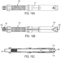
- FIG. 16C is a longitudinal cross sectional view of reduction device 600 taken along section line, N-N.
- reduction device 600 includes an housing tube 501, advancing knob 502, reduction rod 503, cap 504, inner tube 505, retractor sleeve 506, reduction sleeve 507, release ring 508, release ring screw 509, fingers 510, finger springs 511, spring hinge pins 513, finger cam pins 514, finger hinge pins 515, weld sleeve 516, release spring 517, a plurality of ball bearings 518, and finger cover 519.
- reduction device 600 When assembled together, these components form reduction device 600, which comprises a hollow, cylindrical shaped assembly having a first end 602 and a second end 604. First end 602 includes a first assembly opening 606, and second end 604 includes a second assembly opening 608.
- First end 602 includes a first assembly opening 606, and second end 604 includes a second assembly opening 608.
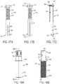
- housing tube 501 of reduction device 600 comprises a hollow, housing tube body 520, having a housing tube first end 522 and a second end 524 opposite housing tube first end 522.
- Housing tube first end 522 is shaped.
- housing tube first end 522 has a hexagonal shape.
- housing tube first end 522 comprises housing tube engagement slots 521.
- housing tube first end 522 includes internal housing tube threads 525.
- Housing tube first end 522 also comprises a first housing tube opening 616, and second end 524 comprises a second housing tube opening 618.
- Housing tube body 520 includes an internal housing tube channel 619 that connects first and second outer tube openings 616/618, respectively.
- Housing tube body 520 includes at second end 524 two diametrically opposed housing tube slots 526, each running from the second end 524 longitudinally along at least a portion of housing tube body 520. Housing tube slots 526 further include a narrow portion 527 connected to a wide portion 528.
- Housing tube body 520 also includes diametrically opposed second housing tube slots 529 disposed at second end 524, but circumferentially offset 90° from housing tube slots 526. Second housing tube slots 529 run from second end 524 longitudinally along at least a portion of housing tube body 520.
- housing tube body 520 includes a gripping section such as a medium diamond knurl 523 etched into a surface of housing tube body 520.
- Advancing knob 502 comprises a hollow, advancing knob body 530, having an advancing knob first end 532 and an advancing knob second end 534 opposite advancing knob first end 532.
- Advancing knob first end 532 is shaped.
- advancing knob first end 532 has a hexagonal shape.
- Advancing knob body 530 also includes an advancing knob annular ring 538 extending therefrom and disposed between a midpoint of advancing knob body 530 and advancing knob first end 532.
- Advancing knob body 530 includes internal advancing knob threading 531 on a portion of its internal surface.
- internal advancing knob threading 531 is disposed from advancing knob second end 534 to just beyond the midpoint of advancing knob body 530 along the internal surface of advancing knob body 530.
- Advancing knob annular ring 538 further includes an advancing knob bearing well 539 that is disposed within advancing knob annular ring 538 annularly about the circumference of advancing knob body 530.
- Advancing knob first end 532 also comprises a first advancing knob opening 626
- advancing knob second end 534 comprises a second advancing knob opening 628.
- Advancing knob body 530 includes an internal advancing knob channel 629 that connects first and second knob openings 626/628, respectively.
- Reduction rod 503 of reduction device 600 comprises a hollow, cylindrical shaped reduction rod body 540, having a first reduction rod end 542 and a second reduction rod end 544 opposite first reduction rod end 542.
- First reduction rod end 542 comprises a first reduction rod opening 543
- second reduction rod end 544 comprises a second reduction rod opening 545.
- Reduction rod body 540 includes an internal reduction rod channel 547 that connects first and second reduction rod openings 543/545, respectively.
- First reduction rod end 542 comprises external reduction rod threads 541 disposed on a portion of the outer surface of reduction rod body 540.
- a first extender 548a extends radially from the outer surface of reduction rod body 540 adjacent second reduction rod end 544.
- a second extender 548b extends radially from the outer surface of reduction rod body 540 adjacent second reduction rod end 544 and diametrically opposed to first extender 548a.
- Reduction rod body 540 also comprises an annular bulbous portion 546 disposed adjacent the midpoint of reduction rod body 540, closer to second reduction rod end 544. Annular bulbous portion 546 has an increased outer diameter compared to the rest of reduction rod body 540.
- Cap 504 of reduction device 600 comprises a hollow, cylindrical-shaped cap body 550, having a first cap end 552 and a second cap end 554 opposite first cap end 552.
- First cap end 552 comprises a first cap opening 556
- second cap end 554 comprises a second cap opening 558
- cap body 550 includes an internal cap channel 557 that connects first cap opening 556 to second cap opening 558.
- second cap end 554 includes external cap threads 551 disposed on the outer surface of cap body 550 and a substantially hemispherical channel disposed around the second cap opening 558 to form a cap bearing well 555.
- Inner tube 505 of reduction device 600 comprises a hollow, cylindrical shaped inner tube body 560, having a first inner tube end 562 and a second inner tube end 564 opposite first inner tube end 562.
- First inner tube end 562 comprises a first inner tube opening 566
- second inner tube end 564 comprises a second inner tube opening 568.
- Inner tube body 560 includes an internal rod channel 567 that connects first and second inner tube openings 566/568, respectively.
- inner tube 505 comprises a first inner tube slot 565a and a second inner tube slot 565b diametrically opposed to first inner tube slot 565a.
- Inner tube body 560 also comprises a first inner tube channel 569a and a second inner tube channel 569b as shown in FIG. 21B .
- Inner tube body 560 comprises a first finger slot 561a and a second finger slot 561b diametrically opposed to first finger slot 561a disposed therein for receiving the fingers 510.
- first left spring pocket 906a and a first right spring pocket 904a are disposed within inner tube body 560, adjacent to and on opposite sides of first finger slot 561a, for receiving finger springs 511.
- second left spring pocket 906b and a second right spring pocket 904b are disposed within inner tube body 560, adjacent to and on opposite sides of second finger slot 561b, for receiving finger springs 511.
- inner tube body 560 comprises finger pin apertures 900 for receiving finger hinge pins 515, and spring pin apertures 902 for receiving spring hinge pins 513.
- Retractor sleeve 506 of reduction device 600 comprises a hollow, cylindrical-shaped retractor sleeve body 570, having a first retractor sleeve end 572 and a second retractor sleeve end 574 opposite first retractor sleeve end 572.
- Retractor sleeve 506 further comprises a first retractor sleeve arm 571 extending longitudinally away from first retractor sleeve end 572 of retractor sleeve body 570 and a second retractor sleeve arm 573 extending longitudinally away from first retractor sleeve end 572, but diametrically opposed to first retractor sleeve arm 571 along the retractor sleeve body 570.
- retractor sleeve 506 comprises a third retractor sleeve arm 575 extending longitudinally away from second retractor sleeve end 574 of retractor sleeve body 570 and a fourth retractor sleeve arm 577 extending longitudinally away from second retractor sleeve end 574, but diametrically opposed to third retractor sleeve arm 575 along retractor sleeve body 570.
- a release spring support ring 578 is formed by a lip disposed around the interior periphery of the retractor sleeve body 570 between the first retractor sleeve end 572 and the second retractor sleeve end 574. The release spring support ring 578 abuts the release spring 517 upon assembly and prevents translation of the release spring.
- Reduction sleeve 507 of reduction device 600 comprises a hollow, cylindrical shaped reduction sleeve body 580, having a first reduction sleeve end 582 and a second reduction sleeve end 584 opposite first reduction sleeve end 582.
- First reduction sleeve end 582 comprises a first reduction sleeve opening 586
- second reduction sleeve end 584 comprises a second reduction sleeve opening 588.
- Reduction sleeve body 580 includes an internal reduction sleeve channel 587 that connects first and second reduction sleeve openings 586 and 588, respectively.
- reduction sleeve 507 comprises reduction rod engagement slots 581 running from first reduction sleeve end 582 longitudinally along a portion of reduction sleeve body 580. It is envisioned in an embodiment that there are two reduction rod engagement slots 581 disposed along reduction sleeve body 580 diametrically opposed to each other.
- Reduction sleeve body 580 also comprises a rod engagement radius 585 disposed therein and at the distal end of second reduction sleeve end 584 and another rod engagement radius 585 disposed therein and at the distal end of second reduction sleeve end 584.
- Reduction sleeve body 580 further comprises reduction sleeve radial reductions 589 disposed therein and at the distal end of second reduction sleeve end 584, offset 90° from rod engagement radii 585.
- Release ring 508 of reduction device 600 comprises a hollow, cylindrical shaped release ring body 590, having a first release ring end 592 and a second release ring end 594 opposite first release ring end 592.
- First release ring end 592 comprises a first release ring opening 596
- second release ring end 594 comprises a second release ring opening 598.
- Release ring body 590 includes an internal release ring channel 597 that connects first and second release ring openings 596/598, respectively.
- release ring 508 may comprise a first release ring feature 591 disposed within release ring body 590 about the circumference of release ring body 590 and a second release ring feature 593 disposed within release ring body 590 about the circumference of release ring body 590, adjacent to first release ring feature 591.
- Release ring 508 may also comprise at least one release ring screw aperture 595 disposed within release ring body 590 for receiving release ring screw 509.
- release ring 508 comprises two diametrically opposed release ring screw apertures 595 for receiving release ring screws 509.
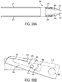
- finger 510 comprises a finger body 660 having a finger first end 662 and a finger second end 664 opposite finger first end 662.
- Finger second end 664 comprises a finger hook 661 having a finger hook undercut 663.
- finger hook undercut 663 may comprise any angle ⁇ above an acute angle.
- finger hook undercut 663 may comprise an angle ⁇ from about 20° to 90°, from about 30° to about 80°, from about 45° to about 75°.
- finger hook undercut 663 may comprise an angle ⁇ from about 40°, about 50°, about 60°, about 70°, about 80°, or about less than 90°.
- Finger body 660 comprises a finger aperture 665 disposed therethrough. Finger body 660 also comprises a first finger extension 670 extending longitudinally from finger body 660 and a second finger extension 672 extending longitudinally from finger body 660 opposite to and spaced apart from first finger extension 670.
- First finger extension 670 comprises a first finger stop 676 disposed at finger first end 662 extending transversely from finger body 660.
- Second finger extension 672 comprises a second finger stop 678 disposed at finger first end 662 extending transversely from finger body 660.
- first and second finger extensions 670 and 672 each comprise a finger slot 680.
- the finger slot 680 comprises three zones: a first zone A, a transition zone B and a third zone C.
- first zone A of the slot comprises a width that is configured and sized such that when finger cam pin 514 is positioned within first zone A, finger cam pin 514 forms a running and sliding fit within first zone A.
- the width of first zone A is defined by upper slot guide 682 and lower slot guide 684 and is sufficient enough to permit finger cam pin 514 to slide within first zone A, but not enough to permit substantial lateral movement transverse to the sliding movement of finger cam pin 514 within first zone A.
- Substantial lateral movement is defined as movement greater than 1/10 th the diameter of the finger cam pin 514.
- Third zone C of finger slot 680 is configured and sized such that it has a width to form a clearance fit with finger cam pin 514.
- third zone C is configured to have a funnel shape such that its shape and size creates a smooth transition from the first zone's width to the maximum width of third zone C.
- Transition zone B provides a smooth transition from the width of the first zone A (i.e., running and sliding fit) to the width of third zone C (i.e., clearance fit).
- finger cam pins 514 are positioned within finger slots 680 such that the finger cam pins engage and run along respective inner finger cam surfaces 688 of finger slots 680. This action will be explained in greater detail below herein.
- finger cam pin 514 are positioned in the third zone C formed by finger cam 686.
- reduction device 600 is moved such that second assembly opening 608 is slid over a tulip head of a polyaxial screw 230 or a uniaxial pedicle screw, the tulip head, when inserted into second assembly opening 608, engages the finger hooks 661 of fingers 510 and forces and/or pushes them outwardly against the force of finger springs 511.
- third zone C provides the clearance to permit the fingers 510 to pivot within rod reduction device 600 in order to permit the tulip head of pedicle screw 230 to insert into second assembly opening 608 of rod reduction device 600.
- weld sleeve 516 comprises a hollow, cylindrical-shaped weld sleeve body 730 having a first weld sleeve end 732 and a second weld sleeve end 734. Disposed at first weld sleeve end 732, body comprises a first weld sleeve opening 736, a second weld sleeve opening 738, and an internal weld sleeve channel 737 connecting the two openings.
- Weld sleeve body 730 comprises diametrically opposed retractor sleeve arm engagement slots 733.
- Second weld sleeve end 734 includes a weld sleeve flange 731.
- finger cover 519 of reduction device 600 is shown having a finger cover body 750.
- Finger cover body 750 includes a finger cover aperture 752 and is curved to closely match the curvature of one or more of the other components.
- first and second finger extensions 670 and 672 of finger 510 are inserted about third retractor sleeve arm 575 of retractor sleeve 506.
- Finger cam pin 514 is inserted through finger slot 680 of first finger extension 670, a third retractor sleeve arm cross pin aperture 1000a disposed within third retractor sleeve arm 575, and through finger slot 680 of second finger extension 672.
- first and second finger extensions 670 and 672 of finger 510 are inserted about fourth retractor sleeve arm 577 of retractor sleeve 506.
- a finger cam pin 514 is also inserted through finger slot 680 of second finger extension 672, a fourth retractor sleeve arm cross pin aperture 1000b disposed within fourth retractor sleeve arm 577, and through finger slot 680 of second finger extension 672.
- the retractor sleeve 506 and finger 510 assembly is inserted over second inner tube end 564 of inner tube body 560 such that fingers 510 slide into first and second finger slots 561a/561b.
- finger springs 511 are placed within first left spring pocket 906a and first right spring pocket 904a.
- One end of finger spring 511 is abutted against a surface of first right spring pocket 904a and the opposite end of finger spring 511 is abutted against first finger stop 676.
- One end of finger spring 511 is abutted against a surface of first left spring pocket 906a and the opposite end of finger spring 511 is abutted against second finger stop 678.
- Finger springs 511 are aligned with spring pin apertures 902 and then spring hinge pins 513 are press fit into the aligned respective spring pin apertures 902 and spring coils. Also, finger aperture 665 is aligned with finger pin aperture 900 and then finger hinge pin 515 is press fit into and through such aligned apertures. The same assembly is performed for the second finger 510. Once assembled, the pins are welded in place using conventional welding processes such as a laser welding process. Pin ends are then polished to be flush with outer surface of inner tube 505.
- finger springs 511 bias fingers 510 radially inward toward a central longitudinal axis of reduction device 600 such that finger hook undercuts 663 of fingers 510 engage tulip head pockets 236 disposed within and on opposite sides of the tulip head 234.
- Tulip head pockets 236 include respective tulip head undercuts 238 that correspond to and engage with finger hook undercuts 163 as shown in FIG. 32B for example.
- Release spring 517 is slid over second inner tube end 564 of inner tube body 560 of inner tube 505 as shown in FIG. 29B .
- Finger cover bodies 750 are fit into respective first and second finger slots 561a/561b as shown in FIGS. 29A and 29B and then may be connected to inner tube body 560 in any number of conventional means such as, for example, welding (e.g., laser welding around periphery of finger cover), snap-fit, etc..
- release ring 508 is slid over housing tube 501.
- Reduction rod 503 is inserted into housing tube 501 as shown in FIG. 30 such that first and second extenders 548a/548b of reduction rod 503 are inserted through and extend from housing tube slots 526 of housing tube 501.
- retractor sleeve 506 /inner tube 505/weld sleeve 516 /fingers 510 assembly shown in FIGS. 29A and 29B is inserted into second end 524 of housing tube 501 such that first and second arms 571/573 of retractor sleeve 506 align with and slide into second housing tube slots 529 of housing tube 501 as shown in FIG. 30 .
- Weld sleeve 516 is connected to housing tube 501 via conventional connection methods, including welding. Additionally, first and second screws 509a/509b are inserted through and threadably engaged with release ring 508, housing tube 501, and respective first and second retractor sleeve arms 571/573. Engagement with first retractor sleeve arm 571 and second retractor sleeve arm 573 is through first retractor sleeve arm screw aperture 579a and second retactor sleeve arm screw aperture 579b respectively.
- reduction sleeve 507 is slid over second end 524 of housing tube 501 such that reduction rod engagement slots 581 abut against and are welded to first and second extenders 548a and 548b of reduction rod 503.
- Advancing knob 502 is inserted into housing tube first end 522 of housing tube 501, a plurality of ball bearings 518 are disposed into advancing knob bearing well 539 of advancing knob annular ring 538 of advancing knob 502, and then cap 504 is threadably engaged to housing tube first end 522 of housing tube 501.
- the cap bearing well 555 interfaces with the ball bearings 518 opposite the advancing knob bearing well 539.
- Reduction adaptor 1100 includes at a first end, an internal hexagonal head (e.g., similar to a socket head), and at a second end, an external hexagonal end, opposite the first end. It is understood that other types, configurations, and shapes of heads can be used.
- the first end can be inserted onto advancing knob first end 532 of advancing knob 502 to engage advancing knob engagement head 536 of advancing knob 502 as shown in FIGS. 33A and 33B .
- an embodiment of pedicle screw 230, size and shape of the pedicle screw 230 and the second assembly opening 608 of the reduction device 600 substantially match.
- the pedicle screw 230 is engaged with minimal freedom of movement.
- the clocking of reduction device 600 to the tulip head 234 of the pedicle screw 230 is from about 0° to about 20°, from about 0° to about 15°, from 0° to about 10°, or from 0° to about 5°.
- the tulip head 234 and corresponding second assembly opening 608 of device 600 has a cross sectional shape that is substantially rectilinear, having rounded corners and curved sidewalls.
- Set screw driver 850 includes a set screw driver body 852 having a set screw engagement head 854 and a driver head 856.
- set screw engagement head 854 includes an external head that has a star-shape which matches and/or corresponds with the internal star-shaped head of the set screw.
- Driver head 856 comprises a substantially square-shaped head.
- the heads of the driver and/or the set screw head can have either internal and/or external heads having any shape, size, and/or configuration.
- FIGS. 32A - 34C are sequential steps in the process of this method for reducing a spinal rod 112/114 into a tulip head 234 of a pedicle screw 230.
- Such a method may be part of a method for correcting or ameliorating spinal aberrations or defects such as, for example, scoliosis, lordosis, and/or kyphosis.
- FIGS. 32A - 34C show the tulip head of pedicle screw 230 fully inserted into second assembly opening 608 of reduction device 600 and in locked engagement, i.e., fingers 510 are fully inserted into respective tulip head pockets 236 on opposite sides of the tulip head 234 such that finger hook undercuts 663 of the fingers 510 are engaged with respective tulip head undercuts 238 of the tulip head pockets 236 of the tulip head 234.
- the tulip head pockets 236 of the tulip head 234 do not extend transversely all the way across the tulip head.
- the tulip head pockets 236 have an upper wall which includes the tulip head undercut 238, a lower wall, and two opposed side walls.
- the tulip head pockets 236 have an upper wall which includes the tulip head undercut 238, a lower wall, and two opposed side walls.
- other configurations may be utilized such as, for example, no side walls and/or bottom wall.
- release ring 508 When release ring 508 is pulled toward first end 602 of device 600, it pulls retractor sleeve 506 respective toward first end 602 which causes finger cam pins 514 to slide along inner finger cam surfaces 688 from third zone C through transition zone B and into first zone A, pulling fingers 510 radially outwardly from the tulip head.
- fingers 510 When the finger cam pins 514 have slide into zone C, fingers 510 are moved into the unlock position, disengaging finger hook undercuts 663 from the corresponding tulip head undercuts 238 of the tulip head pockets 236 of the tulip head 234. In this unlocked position, the tulip head 234 may be removed from the reduction device 600.
- FIGS. 35A and 35B an embodiment of a rod reduction assembly 450 is shown.
- Advancing wheel 456 is in threaded engagement with outer reducer shell 454. Rotation of advancing wheel 456 forces movement of reduction arm 452 relative to the outer reducer shell 454.
- provisional locking instrument 360 is shown.
- the provisional locking instrument 360 is inserted into the central shaft of the rod reduction assembly 450 and provisional locking instrument threads 368 are engaged with internal rod reduction threads 458.
- the threaded engagement advances the provisional locking assembly through the rod reduction assembly 450.
- the provisional locking instrument 360 further comprises a locking sheath 362 which engages the tulip head 234 of a pedicle screw 230 advances the tulip head undercuts 238 against flanged catches of the reduction arm 452.
- the locking sheath 362 engages the tulip head 234 and ceases advancing.
- polyaxial locking tines 364 which engage the screw shaft locking mechanism of the pedicle screw 230.
- the polyaxial locking tines 364 are generally concealed by the locking sheath 362 which is held in a forward position by an advancing spring 366.
- the pedicle screw inserter 380 is used to insert a pedicle screw, for example a polyxial screw 230, into a patient.
- the pedicle screw inserter 380 comprises a central tightening shaft 382, a handle 384, a friction sleeve 386, and a screw head engagement sleeve 388.
- the central tightening shaft 382 has a driver tip 394 shaped to match the drive head of the pedicle screw shaft.
- the driver tip 394 may be a hexalobe.
- the screw head engagement sleeve 388 has screw head engagement threads 390.
- the screw head engagement threads mate with the internal threads of a pedicle screw to secure the screw head engagement sleeve 388 and a pedicle screw together.
- the handle 384 and friction sleeve 386 allow for free rotation of the central tightening shaft 382.
- the screw head engagement sleeve 388 is engaged with the head of a pedicle screw.
- the driver tip 394 of the central tightening shaft 382 is aligned with the mating feature of the pedicle screw.
- the friction sleeve 386 and handle 384 are moved along the central tightening shaft until the friction sleeve interlocks with the head of the pedicle screw as shown in FIG. 38 .
- the central tightening shaft 382 is rotated which rotates the shaft of the pedicle screw through the engagement with the driver tip 394.
- the interlock between the friction sleeve 386 and the head of the pedicle screw helps prevent the screw head engagement sleeve from unthreading during the pedicle screw insertion process.
- the friction sleeve 386 and central tightening shaft 382 rotate in unison as they are both engaged with the head of the pedicle screw.
- a thoracic facetectomy is performed.
- the facet joints are cleaned and rongeurs are used to perform a partial inferior articular process osteotomy. This is done to enhance visualization.
- 3 mm to 5 mm of the inferior facet is removed and the articular cartilage of the superior facets is removed, except for on the lowest vertebra to be instrumented. This allows for the intraoperative localization of the thoracic pedicle screw starting points and enhances fusion.
- the pedicles are subsequently prepared.
- a pedicle awl or burr is used to create a 3 mm deep posterior cortical breach.
- the pedicle awl may be advanced by gently twisting the handle with light pressure.
- a pedicle blush may be visualized suggesting entrance into the cancellous bone at the base of the pedicle but the blush may not be evident when preparing small pedicles due to the limited intrapedicular cancellous bone.
- This procedure should be performed with the tip of the pedicle probe pointed laterally to avoid perforation of the medial cortex. Gripping the sides of the handle to avoid applying too much ventral pressure, the tip of the probe is inserted approximately 2 mm to approximately 25 mm. The probe is oriented so that the flat surface of the probe is in the same plane as the curve of the pedicle, then removed and reinserted with the tip pointed medially. The probe is advanced to the desired depth and rotated approximately 180° to ensure adequate room for a screw. The feeler probe is advanced to the base of the hole, alternatively called the floor, to confirm five distinct bony borders. The five bony borders being a floor and four walls (medial, lateral, superior, and inferior). When necessary, bone wax or other hemostatic agent may be placed in the pedicle hole to limit bleeding, and then the probe may be repositioned with a more appropriate trajectory.
- the pedicle is undertapped for the appropriate screw size.
- a flexible feeler probe may be used to verify presence of threads in the tapped hole.
- a feeler probe is advanced to the floor of the hole and a hemostat is clamped to the feeler probe at the point where it exits the pedicle.
- the appropriate screw diameter and length may subsequently be selected based on both preoperative measurement and intraoperative observation. The same technique is repeated for each of the remaining pedicles that need to be instrumented.
- Roentgenographic assistance using plain radiographs or fluoroscopy may be utilized to ensure proper screw trajectory.
- Pedicle markers are placed into the holes of the pedicles and a lateral view is obtained.
- An anterior-posterior view may also be obtained.
- Pedicle screws 230 are placed in each prepared pedicle. Selection of uniaxial or polyaxial screws 230 is at the discretion of the surgeon with both options being anticipated. The screws should be advanced slowly through the pedicle to ensure proper tracking. The pedicle screws 230 should be placed at every segment that allows free passage of a pedicle screw on the correction side of the spine and every third or fourth level on the supportive side. At the proximal and distal end of the supportive side at least two screws should be inserted. Addition of more screws will result in greater construct rigidity. Upon placement of the screws they should be checked radiographically to ensure intraosseous screw placement. Should it be determined that a pedicle is too narrow to cannulate, alternate fixation methods such as hooks 210, 220, wires or tapes may be used.
- the spinal rods 112, 114 are prepared.
- the spinal rods 112, 114 are measured and contoured in the sagittal and coronal planes. When contouring, the spinal rods 112, 114 may be clamped at both ends with rod grippers to help prevent the rod from rotating.
- the first rod is placed into the previously inserted screws.
- a rocker a rod reduction assembly 450, or a reduction device 600 may be used.
- the rocker method is an effective method for reducing the rod into the implant when only a slight height difference exists between the rod and the implant saddle.
- the sides of the implant are grasped with the rocker cam above the rod.
- the rocker is levered backwards over the rod to seat the rod into the saddle of the implant.
- a set screw is subsequently placed and provisionally tightened to hold the rod in place.
- the rod reduction assembly 450 For reduction of the rod using the rod reduction assembly 450, with the pedicle screw and rod in place the rod reduction assembly is applied over the head of the screw.
- the provisional locking instrument 360 is inserted down the tube of the rod reduction assembly 450 and threaded down to engage the provisional locking feature.
- the provisional locking instrument 360 may be inserted down the tube of the rod reduction assembly 450 and partially threaded down prior to affixing the rod reduction assembly to the screw head.
- the rod is then reduced by turning the advancing wheel 456 of the rod reduction assembly 450. If greater torque is required to reduce the rod, a reduction adaptor 1100 attached to an axial or torque limiting T-handle may interface with the advancing wheel 456 of the rod reduction assembly 450.
- a set screw driver 850 is used to introduce a set screw.
- the set screw is passed down the central cavity of the rod reduction assembly 450 until it bottoms out on the screw threads.
- the set screw is turned counterclockwise until a click is felt and then turned clockwise to tighten.
- the red reduction device is applied over the tulip head 234 of the screw.
- the fingers 510 of the rod reduction device 600 engage the tulip head pockets 236 of the pedicle screw tulip head 234.
- the rod is then reduced by turning the advancing knob 502 of the rod reduction device 600.
- a reduction adaptor 1100 attached to an axial or torque limiting T-handle may interface with the advancing knob 502 of the rod reduction device 600.
- a set screw driver 850 is used to introduce a set screw.
- the set screw is passed through the first assembly opening 606 of the rod reduction device 600 until it bottoms out on the screw threads. To avoid cross threading of the set screw, the set screw is turned counterclockwise until a click is felt and then turned clockwise to tighten.
- the spinal rod 112, 114 While leaving the set screws loose or only locked at one end, the spinal rod 112, 114 is slowly straightened using tubular benders. Fully straightening the spinal rod 112, 114 may require several passes.
- the contoured rod is rotated into its final position.
- the rotation must be done slowly to prevent rapid neurologic changes and/or injury to the spinal cord.
- the contoured rod is rotated into the desired position.
- the apical set screws are tightened and compression or distraction may be performed. During all the correction maneuvers the screw and bone interface should be monitored.
- the second rod and its respective set screws are placed according to the techniques previously outlined. Following placement of the second rod and set screws, convex compressive forces are placed on the segments using a parallel compressor to horizontalize the lowest instrumented vertebra and mildly compress the convexity of the deformity. It is preferred that compression be released just prior to final tightening. This technique helps ensure that the implant head and rod are normalized to one another and allows for the rod to be fully seated in the implant head during the final tightening step.
- the counter torque wrench and the set screw driver 850 are placed onto the open screw, saddle, and set screw.
- a torque limiting T-handle is placed on the set screw driver 850 and turned clockwise while firmly holding the counter torque wrench.
- the torque liming T-handle is preferably set to 70 in-lbs. The T-handle is turned clockwise until an audible click is heard indicating the proper torque has been met.
- cross connectors are placed.
- the cross connector connection provides rotational stability to the construct as a framed construct resists rotational forces.
- the cross connectors should be placed close to the construct extremities but placement at other positions along the construct is also envisioned.
- references herein of a component of the present disclosure being “configured” to embody a particular property, or function in a particular manner, are structural recitations, as opposed to recitations of intended use. More specifically, the references herein to the manner in which a component is “configured” denotes an existing physical condition of the component and, as such, is to be taken as a definite recitation of the structural characteristics of the component.
Description
- This application claims priority to
U.S. Provisional Application Ser. No. 61/646,030 filed May 11, 2012 U.S. Provisional Application Ser. No. 61/798,414 filed March 15, 2013 - The present disclosure relates to a system and technique for spinal surgery. Spinal implants, including connectors, hooks, screws and rods, are used to correct spinal deformities. Screws and connectors in combination with spinal rods can align and correct deformities in the natural spinal alignment as well as repair traumatic injury. Additionally, instrumentation for reduction of spinal rods into spinal pedicle screws is provided in the present disclosure.
- Spinal fixation systems may be used in surgery to fix, adjust, and/or align the spinal column. One type of spinal fixation system employs a spinal rod for supporting the spine and fixing, adjusting, and/or aligning the spinal column into the desired orientation. Attachment of the spinal rod to the spinal column has been achieved using a variety of vertebral anchors. Vertebral anchors include screws, hooks, pins, and bolts used to engage the vertebrae and connect the spinal rod to different vertebrae.
- The length and diameter of the spinal rod depends on the size and number of vertebrae to be held in a desired position by the spinal fixation system. The size of the spinal rod also depends on the region of the spine where the spinal fixation system is used. For example, in the cervical region of the spine, where the vertebrae tend to be smaller, a relatively smaller spinal rod is used. Conversely, in the thoracic region, where heavier loads are experienced and the vertebrae tend to be larger, a spinal rod having a relatively larger diameter is used. The cervico-thoracic junction of the spine is typically instrumented using spinal rods of two different diameters to accommodate anatomical differences between the cervical and thoracic spine regions. To accommodate a spinal fixation system including spinal rods having different sizes and configurations, a rod connector may be used to join a first spinal rod and a second spinal rod together. The rod connector may be a side-by-side connector, where the ends of the two spinal rods are placed side-by-side and connected using a connector that spans the two ends, or an axial connector, which aligns the axes of the two spinal rods and connects the ends of the spinal rods together along the axial direction. The plurality of possible spinal rod diameters in combination with the plurality of connector arrangements results in a surgeon typically requiring a vast array of connectors on hand in preparation for a given spinal surgery.
- The spinal rods in a spinal fixation system may necessarily be bent to conform to a desired curvature of the spinal column in one or more of the anatomic planes as part of a spinal fixation or corrective surgery. Attachment of spinal rods to vertebral anchors such as screws, hooks, pins, and bolts may be complicated by differing curvature of the untreated spine and the curvature of the spinal rod. Instrumentation to force the spinal rod into engagement with the vertebral anchors may be used. Challenges arise in utilizing instrumentation to force the spinal rod into engagement with the vertebral anchors because the instrumentation generally must be releasably affixed to a previously implanted vertebral anchor and the locking mechanism on the vertebral anchor must be engaged while maintaining the spinal rod in the correct position. Simple engagement of the instrumentation with the vertebral anchor is desirable.
-
WO95/25473 WO02/09603 US6217578 discloses a spinal cross connector which connects a pair of longitudinally extending rods anchored to the spine. The cross connector has a first element, including a body, a rod gripping portion formed on a first end of the body and a circular arm extending along a first axis from a second end of the body. A second element is provided which has a body, a rod gripping portion formed on one end and a flange having a bore on a second end. The flange has a bearing surface surrounding the bore and another bearing surface it formed on the inner surface of the bore. A pivot element has a head portion, including a bore therethrough for engaging the arm on the first element. The pivot element has a threaded portion extending from the head along a second axis and a generally cylindrical bearing surface engageable with the bearing surface inside the bore. A lock nut is operatively engageable with the threaded portion on the pivot element to lock the assembly together.US5053034 discloses a spinal joint for use in spinal surgery which includes two blocks pivotally connected to each other. One block is secured to a vertebrae with a bone screw, which the other block connects to another spinal joint. The blocks rotate relative to one another, and can be locked relative to one another in various angular positions. Serrations on one block engage with corresponding serrations in the pivotal connection portion of the second block at a selected angle, and are locked in place by a locking screw.US6648888 discloses a surgical instrument comprising a first device including an actuatable clamp for clamping on a fastener fixed to a first bone portion and a carriage that is movable relative to the clamp when subjected to a predetermined axial load. A second device includes a portion adapted for threaded engagement with the carriage and an end portion for supporting a member for securing a rod connected to a second bone portion to the fastener. Relative rotation between the first and second devices causes relative axial movement between the second device and the carriage of the first-device. The carriage is stationary relative to the clamp of the first device when a force necessary to produce relative movement between the first and second bone portions is below the predetermined axial load so that relative rotation between the first and second devices first bone portion relative to the second bone portion.US2006089651 discloses a surgical tool for anchoring spinal rod, which has set of pivot connections allowing shifting of clamp actuator to shift jaws and generating securing force on clamp actuator to maintain jaws in clamped position. The apparatus has a clamping mechanism generating a clamping force applied by clamping jaws to a coupling device. A clamp actuator of the clamping mechanism shifts the jaws between a release and clamped positions. A set of pivot connections of the mechanism allows shifting of the clamp actuator to shift the jaws, and generates a securing force on the clamp actuator to maintain the jaws in the clamped position. - In one embodiment, a medical instrument having a rod reduction assembly and a pedicle screw engaging assembly is provided. The rod reduction assembly comprises a rod reduction sleeve, a reduction rod, and an advancing knob. The reduction sleeve comprises a hollow, cylindrical shaped body having an internal reduction sleeve channel, reduction rod engagement slots on a first end, and rod engagement radii on a second end. The reduction rod comprises external reduction rod threads on a first end and the advancing knob comprises internal threads matched to the external reduction rod threads. The reduction rod has first and second extenders extending radial from the outer surface proximal a second end which engage with the reduction rod engagement slots. The pedicle screw engaging assembly has fingers for engagement with the head of a pedicle screw, finger cam pins, an inner tube, and a release ring. The fingers each comprise a finger hook having a finger hook undercut, a finger slot, and a finger aperture. The finger slot have a first end distal the finger hook with a width sufficient to permit finger cam pin to slide through but not enough for substantial lateral movement transverse to the sliding direction and a second end proximal the finger hook with a larger width to form a clearance fit with the finger cam pin. The inner tube comprises a hollow, cylindrical body having a first inner tube end and a second inner tube end, a first inner tube slot and a second inner tube slot diametrically opposed across the cylindrical body, and a first finger slot and a second finger slot diametrically opposed across the cylindrical body. The first inner tube slot and the second inner tube slot are open toward the second inner tube end and the fingers are disposed in the first finger slot and the second finger slot with the fingers oriented to dispose the finger hooks proximal the second inner tube end and the finger hook undercuts toward the interior of the inner tube.
- Movement of the release ring from a first position to a second position moves the finger cam pins from the second end of the finger slot to the first end of the finger slot thereby positioning the fingers for insertion of the head of a pedicle screw.
- The following detailed description of specific embodiments of the present disclosure can be best understood when read in conjunction with the following drawings, where like structure is indicated with like reference numerals and in which:
-
FIG. 16A is a profile view of an embodiment of a rod reduction device; -
FIG. 16B is a profile view of an embodiment of a rod reduction device; -
FIG. 16C is a section view of an embodiment of a rod reduction device; -
FIG. 17A is a profile view of an embodiment of a housing tube of a rod reduction device; -
FIG. 17B is a profile view of an embodiment of a housing tube of a rod reduction device; -
FIG. 17C is a section view of an embodiment of a housing tube of a rod reduction device; -
FIG. 18A is a front profile view of an embodiment of an advancing knob of a rod reduction device; -
FIG. 18B is a profile view of an embodiment of an advancing knob of a rod reduction device; -
FIG. 19A is a front profile view of an embodiment of a reduction rod of a rod reduction device; -
FIG. 19B is a section view of an embodiment of a reduction rod of a rod reduction device; -
FIG. 20 is a section view of an embodiment of a cap of a rod reduction device; -
FIG. 21A is a front profile of an embodiment of a inner tube of a rod reduction device; -
FIG. 21B is a side profile of an embodiment of a inner tube of a rod reduction device; -
FIG. 21C is a front section view of an embodiment of a inner tube of a rod reduction device; -
FIG. 21D is a top section view of an embodiment of a inner tube of a rod reduction device; -
FIG. 22A is a front view of an embodiment of a retractor sleeve of a rod reduction device; -
FIG. 22B is a side view of an embodiment of a retractor sleeve of a rod reduction device; -
FIG. 22C is a front section view of an embodiment of a retractor sleeve of a rod reduction device; -
FIG. 23 is an isometric view of an embodiment of a reduction sleeve of a rod reduction device; -
FIG. 24A is a front view of an embodiment of a release ring of a rod reduction device; -
FIG. 24B is a section view of an embodiment of a release ring of a rod reduction device; -
FIG. 25A is an isometric view of an embodiment of a finger of a rod reduction device; -
FIG. 25B is a section view of an embodiment of a finger of a rod reduction device; -
FIG. 25C is a top view of an embodiment of a finger of a rod reduction device; -
FIG. 25D is a section view of an embodiment of a finger of a rod reduction device; -
FIG. 26A is a front view of an embodiment of a weld sleeve of a rod reduction device; -
FIG. 26B is a side view of an embodiment of a weld sleeve of a rod reduction device; -
FIG. 26C is a section view of an embodiment of a weld sleeve of a rod reduction device; -
FIG. 26D is a top view of an embodiment of a weld sleeve of a rod reduction device; -
FIG. 27 is an isometric view of an embodiment of a finger cover of a rod reduction device; -
FIG. 28A is a sub-assembly of an embodiment of a rod reduction device; -
FIG. 28B is a detail view of a sub-assembly of an embodiment of a rod reduction device; -
FIG. 29A is a sub-assembly of an embodiment of a rod reduction device; -
FIG. 29B is a sub-assembly of an embodiment of a rod reduction device; -
FIG. 30A is a sub-assembly of an embodiment of a rod reduction device; -
FIG. 30B is a sub-assembly of an embodiment of a rod reduction device; -
FIG. 30C is an exploded view of an embodiment of a rod reduction device; -
FIG. 31 is a front profile view of an embodiment of a set screw driver; -
FIG. 32A is a side view of an embodiment of a rod reduction device attached to a spinal pedicle screw; -
FIG. 32B is a section view of an embodiment of a rod reduction device attached to a spinal pedicle screw; -
FIG. 32C is a detail section view of an embodiment of a rod reduction device attached to a spinal pedicle screw; -
FIG. 33A is a side view of an embodiment of a rod reduction device attached to a spinal pedicle screw with the reduction sleeve engaging a spinal rod; -
FIG. 33B is a section view of an embodiment of a rod reduction device attached to a spinal pedicle screw with the reduction sleeve engaging a spinal rod; -
FIG. 33C is a detail section view of an embodiment of a rod reduction device attached to a spinal pedicle screw with the reduction sleeve engaging a spinal rod; -
FIG. 34A is a side view of an embodiment of a rod reduction device attached to a spinal pedicle screw, a spinal rod reduced into the spinal pedicle screw, and a rod retaining set screw inserted; -
FIG. 34B is a section view of an embodiment of a rod reduction device attached to a spinal pedicle screw, a spinal rod reduced into the spinal pedicle screw, and a rod retaining set screw inserted; -
FIG. 34C is a detail section view of an embodiment of a rod reduction device attached to a spinal pedicle screw, a spinal rod reduced into the spinal pedicle screw, and a rod retaining set screw inserted; -
FIG. 35A is a front profile view of an embodiment of a rod reduction assembly; -
FIG. 35B is a section view of an embodiment of a rod reduction assembly; -
FIG. 36A is a section view of an embodiment of a provisional locking instrument; -
FIG. 36B is a profile view of an embodiment of a provisional locking instrument; -
FIG. 37A is a front profile view of an embodiment of a spinal pedicle screw inserter; -
FIG. 37B is a section view of an embodiment of a spinal pedicle screw inserter; -
FIG. 37C is a detail section view of an embodiment of a spinal pedicle screw inserter; -
FIG. 38 is a front profile view of an embodiment of a spinal pedicle screw inserter; -
FIG. 39 is a front profile view of an embodiment of a spinal pedicle screw; -
FIG. 40A is a side profile view of an embodiment of a spinal pedicle screw; -
FIG. 40B is a front profile view of an embodiment of a spinal pedicle screw; -
FIG. 40C is a top profile view of an embodiment of a spinal pedicle screw; and -
FIG. 40D is a section view of an embodiment of a spinal pedicle screw. - Referring to
FIG. 39 , a front profile of apolyaxial screw 230. Thepolyaxial screw 230 comprises ascrew saddle 232 for receiving a spinal rod 112, 114 or lateral connector rod 192 for example. The rod receiving geometry of thescrew saddle 232 is envisioned being configured to match the rod receiving geometry of the open rod receiving saddle 222 of the open laminar hook 220 for acceptance of multiple diameter spinal rods including a 5.5 mm diameter spinal rod 112 or a 4.75 mm diameter spinal rod 114. Uniaxial screws with a similar rod receiving geometry for securing multiple diameter spinal rods 112, 114 are also envisioned. - While reference is made throughout this disclosure to dual-diameter connectors, dual-diameter hooks, and dual-diameter screws, it is envisioned that the technique used to allow acceptance of two diameters of rods can be modified to allow three or more diameters of rods.
- Referring to
FIGS. 16A - 16C , arod reduction device 600 is shown.FIG. 16C is a longitudinal cross sectional view ofreduction device 600 taken along section line, N-N. In the illustrative embodiment shown,reduction device 600 includes anhousing tube 501, advancingknob 502,reduction rod 503,cap 504,inner tube 505,retractor sleeve 506,reduction sleeve 507,release ring 508,release ring screw 509,fingers 510, finger springs 511, spring hinge pins 513, finger cam pins 514, finger hinge pins 515,weld sleeve 516,release spring 517, a plurality ofball bearings 518, andfinger cover 519. When assembled together, these components formreduction device 600, which comprises a hollow, cylindrical shaped assembly having afirst end 602 and asecond end 604.First end 602 includes afirst assembly opening 606, andsecond end 604 includes asecond assembly opening 608. Each of the components set forth above will be individually described below herein and shown in separate figures. In addition, it will be shown and described below herein how each of the components ofreduction device 600 are interconnected and, once assembled, howreduction device 600 works in operation. - Referring to
FIGS. 17A - 17C ,housing tube 501 ofreduction device 600 is shown.Housing tube 501 comprises a hollow,housing tube body 520, having a housing tubefirst end 522 and asecond end 524 opposite housing tubefirst end 522. Housing tubefirst end 522 is shaped. In this example, housing tubefirst end 522 has a hexagonal shape. Additionally, in this example housing tubefirst end 522 comprises housingtube engagement slots 521. Also, housing tubefirst end 522 includes internalhousing tube threads 525. Housing tubefirst end 522 also comprises a firsthousing tube opening 616, andsecond end 524 comprises a secondhousing tube opening 618.Housing tube body 520 includes an internalhousing tube channel 619 that connects first and secondouter tube openings 616/618, respectively.Housing tube body 520 includes atsecond end 524 two diametrically opposedhousing tube slots 526, each running from thesecond end 524 longitudinally along at least a portion ofhousing tube body 520.Housing tube slots 526 further include anarrow portion 527 connected to awide portion 528. -
Housing tube body 520 also includes diametrically opposed secondhousing tube slots 529 disposed atsecond end 524, but circumferentially offset 90° fromhousing tube slots 526. Secondhousing tube slots 529 run fromsecond end 524 longitudinally along at least a portion ofhousing tube body 520. Optionally,housing tube body 520 includes a gripping section such as amedium diamond knurl 523 etched into a surface ofhousing tube body 520. - Referring to
FIGS. 18A and 18B , advancingknob 502 ofreduction device 600 is shown. Advancingknob 502 comprises a hollow, advancingknob body 530, having an advancing knobfirst end 532 and an advancing knobsecond end 534 opposite advancing knobfirst end 532. Advancing knobfirst end 532 is shaped. In this example, advancing knobfirst end 532 has a hexagonal shape. Advancingknob body 530 also includes an advancing knobannular ring 538 extending therefrom and disposed between a midpoint of advancingknob body 530 and advancing knobfirst end 532. Advancingknob body 530 includes internal advancing knob threading 531 on a portion of its internal surface. In this example, internal advancing knob threading 531 is disposed from advancing knobsecond end 534 to just beyond the midpoint of advancingknob body 530 along the internal surface of advancingknob body 530. Advancing knobannular ring 538 further includes an advancing knob bearing well 539 that is disposed within advancing knobannular ring 538 annularly about the circumference of advancingknob body 530. Advancing knobfirst end 532 also comprises a first advancingknob opening 626, and advancing knobsecond end 534 comprises a second advancingknob opening 628. Advancingknob body 530 includes an internal advancingknob channel 629 that connects first andsecond knob openings 626/628, respectively. - Referring to
FIGS. 19A and 19B ,reduction rod 503 ofreduction device 600 is shown.Reduction rod 503 comprises a hollow, cylindrical shapedreduction rod body 540, having a firstreduction rod end 542 and a secondreduction rod end 544 opposite firstreduction rod end 542. Firstreduction rod end 542 comprises a firstreduction rod opening 543, and secondreduction rod end 544 comprises a secondreduction rod opening 545.Reduction rod body 540 includes an internalreduction rod channel 547 that connects first and secondreduction rod openings 543/545, respectively. Firstreduction rod end 542 comprises externalreduction rod threads 541 disposed on a portion of the outer surface ofreduction rod body 540. Afirst extender 548a extends radially from the outer surface ofreduction rod body 540 adjacent secondreduction rod end 544. Asecond extender 548b extends radially from the outer surface ofreduction rod body 540 adjacent secondreduction rod end 544 and diametrically opposed tofirst extender 548a.Reduction rod body 540 also comprises an annularbulbous portion 546 disposed adjacent the midpoint ofreduction rod body 540, closer to secondreduction rod end 544. Annularbulbous portion 546 has an increased outer diameter compared to the rest ofreduction rod body 540. - Referring to
FIG. 20 ,cap 504 ofreduction device 600 is shown.Cap 504 comprises a hollow, cylindrical-shapedcap body 550, having afirst cap end 552 and asecond cap end 554 oppositefirst cap end 552.First cap end 552 comprises afirst cap opening 556,second cap end 554 comprises asecond cap opening 558, andcap body 550 includes aninternal cap channel 557 that connectsfirst cap opening 556 tosecond cap opening 558. Also,second cap end 554 includes external cap threads 551 disposed on the outer surface ofcap body 550 and a substantially hemispherical channel disposed around the second cap opening 558 to form a cap bearing well 555. - Referring to
FIGS. 21A - 21D ,inner tube 505 ofreduction device 600 is shown.Inner tube 505 comprises a hollow, cylindrical shapedinner tube body 560, having a firstinner tube end 562 and a secondinner tube end 564 opposite firstinner tube end 562. Firstinner tube end 562 comprises a firstinner tube opening 566, and secondinner tube end 564 comprises a secondinner tube opening 568.Inner tube body 560 includes aninternal rod channel 567 that connects first and secondinner tube openings 566/568, respectively. As shown inFIGS. 21A and 21C ,inner tube 505 comprises a firstinner tube slot 565a and a secondinner tube slot 565b diametrically opposed to firstinner tube slot 565a.Inner tube body 560 also comprises a firstinner tube channel 569a and a secondinner tube channel 569b as shown inFIG. 21B .Inner tube body 560 comprises afirst finger slot 561a and asecond finger slot 561b diametrically opposed tofirst finger slot 561a disposed therein for receiving thefingers 510. - Also, a first
left spring pocket 906a and a firstright spring pocket 904a are disposed withininner tube body 560, adjacent to and on opposite sides offirst finger slot 561a, for receiving finger springs 511. Similarly, a secondleft spring pocket 906b and a secondright spring pocket 904b are disposed withininner tube body 560, adjacent to and on opposite sides ofsecond finger slot 561b, for receiving finger springs 511. In addition,inner tube body 560 comprisesfinger pin apertures 900 for receiving finger hinge pins 515, andspring pin apertures 902 for receiving spring hinge pins 513. - Referring to
FIGS. 22A - 22C ,retractor sleeve 506 ofreduction device 600 is shown.Retractor sleeve 506 comprises a hollow, cylindrical-shapedretractor sleeve body 570, having a firstretractor sleeve end 572 and a secondretractor sleeve end 574 opposite firstretractor sleeve end 572.Retractor sleeve 506 further comprises a firstretractor sleeve arm 571 extending longitudinally away from firstretractor sleeve end 572 ofretractor sleeve body 570 and a secondretractor sleeve arm 573 extending longitudinally away from firstretractor sleeve end 572, but diametrically opposed to firstretractor sleeve arm 571 along theretractor sleeve body 570. Additionally,retractor sleeve 506 comprises a thirdretractor sleeve arm 575 extending longitudinally away from secondretractor sleeve end 574 ofretractor sleeve body 570 and a fourthretractor sleeve arm 577 extending longitudinally away from secondretractor sleeve end 574, but diametrically opposed to thirdretractor sleeve arm 575 alongretractor sleeve body 570. Additionally, a releasespring support ring 578 is formed by a lip disposed around the interior periphery of theretractor sleeve body 570 between the firstretractor sleeve end 572 and the secondretractor sleeve end 574. The releasespring support ring 578 abuts therelease spring 517 upon assembly and prevents translation of the release spring. - Referring to
FIG. 23 ,reduction sleeve 507 ofreduction device 600 is shown.Reduction sleeve 507 comprises a hollow, cylindrical shapedreduction sleeve body 580, having a firstreduction sleeve end 582 and a secondreduction sleeve end 584 opposite firstreduction sleeve end 582. Firstreduction sleeve end 582 comprises a firstreduction sleeve opening 586, and secondreduction sleeve end 584 comprises a secondreduction sleeve opening 588.Reduction sleeve body 580 includes an internalreduction sleeve channel 587 that connects first and secondreduction sleeve openings reduction sleeve 507 comprises reductionrod engagement slots 581 running from firstreduction sleeve end 582 longitudinally along a portion ofreduction sleeve body 580. It is envisioned in an embodiment that there are two reductionrod engagement slots 581 disposed alongreduction sleeve body 580 diametrically opposed to each other. - Along the same sides of
reduction sleeve body 580 as reductionrod engagement slots 581, reductionsleeve viewing apertures 583 are positioned adjacent to and/or near secondreduction sleeve end 584.Reduction sleeve body 580 also comprises arod engagement radius 585 disposed therein and at the distal end of secondreduction sleeve end 584 and anotherrod engagement radius 585 disposed therein and at the distal end of secondreduction sleeve end 584.Reduction sleeve body 580 further comprises reduction sleeveradial reductions 589 disposed therein and at the distal end of secondreduction sleeve end 584, offset 90° fromrod engagement radii 585. - Referring to
FIGS. 24A and 24B ,release ring 508 ofreduction device 600 is shown.Release ring 508 comprises a hollow, cylindrical shapedrelease ring body 590, having a firstrelease ring end 592 and a secondrelease ring end 594 opposite firstrelease ring end 592. Firstrelease ring end 592 comprises a firstrelease ring opening 596, and secondrelease ring end 594 comprises a secondrelease ring opening 598.Release ring body 590 includes an internalrelease ring channel 597 that connects first and secondrelease ring openings 596/598, respectively. Additionally,release ring 508 may comprise a firstrelease ring feature 591 disposed withinrelease ring body 590 about the circumference ofrelease ring body 590 and a secondrelease ring feature 593 disposed withinrelease ring body 590 about the circumference ofrelease ring body 590, adjacent to firstrelease ring feature 591.Release ring 508 may also comprise at least one releasering screw aperture 595 disposed withinrelease ring body 590 for receivingrelease ring screw 509. In anembodiment release ring 508 comprises two diametrically opposed releasering screw apertures 595 for receiving release ring screws 509. - Referring back to
FIG. 16C ,reduction device 600 comprises a twofingers 510 diametrically opposed to each other. Now referring toFIGS. 25A - 25D ,finger 510 comprises afinger body 660 having a fingerfirst end 662 and a fingersecond end 664 opposite fingerfirst end 662. Fingersecond end 664 comprises afinger hook 661 having a finger hook undercut 663. In one example, finger hook undercut 663 may comprise any angle α above an acute angle. In another example, finger hook undercut 663 may comprise an angle α from about 20° to 90°, from about 30° to about 80°, from about 45° to about 75°. In still another example, finger hook undercut 663 may comprise an angle α from about 40°, about 50°, about 60°, about 70°, about 80°, or about less than 90°. -
Finger body 660 comprises afinger aperture 665 disposed therethrough.Finger body 660 also comprises afirst finger extension 670 extending longitudinally fromfinger body 660 and asecond finger extension 672 extending longitudinally fromfinger body 660 opposite to and spaced apart fromfirst finger extension 670.First finger extension 670 comprises afirst finger stop 676 disposed at fingerfirst end 662 extending transversely fromfinger body 660.Second finger extension 672 comprises asecond finger stop 678 disposed at fingerfirst end 662 extending transversely fromfinger body 660. - Referring specifically to
FIG. 25D along withFIGS. 25A - 25C , first andsecond finger extensions finger slot 680. Thefinger slot 680 comprises three zones: a first zone A, a transition zone B and a third zone C. In particular, first zone A of the slot comprises a width that is configured and sized such that whenfinger cam pin 514 is positioned within first zone A,finger cam pin 514 forms a running and sliding fit within first zone A. As example, the width of first zone A is defined byupper slot guide 682 andlower slot guide 684 and is sufficient enough to permitfinger cam pin 514 to slide within first zone A, but not enough to permit substantial lateral movement transverse to the sliding movement offinger cam pin 514 within first zone A. Substantial lateral movement is defined as movement greater than 1/10th the diameter of thefinger cam pin 514. Third zone C offinger slot 680 is configured and sized such that it has a width to form a clearance fit withfinger cam pin 514. As an example, third zone C is configured to have a funnel shape such that its shape and size creates a smooth transition from the first zone's width to the maximum width of third zone C. Transition zone B provides a smooth transition from the width of the first zone A (i.e., running and sliding fit) to the width of third zone C (i.e., clearance fit). In operation, finger cam pins 514 are positioned withinfinger slots 680 such that the finger cam pins engage and run along respective inner finger cam surfaces 688 offinger slots 680. This action will be explained in greater detail below herein. - As such, when
fingers 510 are in the spring-biased radially inwardly position (i.e., a normal position),finger cam pin 514 are positioned in the third zone C formed byfinger cam 686. Whenreduction device 600 is moved such that second assembly opening 608 is slid over a tulip head of apolyaxial screw 230 or a uniaxial pedicle screw, the tulip head, when inserted into second assembly opening 608, engages the finger hooks 661 offingers 510 and forces and/or pushes them outwardly against the force of finger springs 511. As thefingers 510 are pushed outwardly, the fingers pivot about finger hinge pins 515 such that finger first ends 662 move radially inward, causing finger cam pins 514 (which are still positioned within third zone C and engaged against respective inner finger cam surfaces 688 to move away from engagement with respective inner finger cam surfaces 688 within third zone C up and, optionally to engagement with respective outerfinger cam surface 689. The clearance fit of third zone C provides the clearance to permit thefingers 510 to pivot withinrod reduction device 600 in order to permit the tulip head ofpedicle screw 230 to insert into second assembly opening 608 ofrod reduction device 600. - Referring to
FIGS. 26A - 26D ,weld sleeve 516 is shown.Weld sleeve 516 comprises a hollow, cylindrical-shapedweld sleeve body 730 having a firstweld sleeve end 732 and a secondweld sleeve end 734. Disposed at firstweld sleeve end 732, body comprises a firstweld sleeve opening 736, a second weld sleeve opening 738, and an internalweld sleeve channel 737 connecting the two openings.Weld sleeve body 730 comprises diametrically opposed retractor sleevearm engagement slots 733. Secondweld sleeve end 734 includes aweld sleeve flange 731. - Referring to
FIG. 27 ,finger cover 519 ofreduction device 600 is shown having afinger cover body 750.Finger cover body 750 includes afinger cover aperture 752 and is curved to closely match the curvature of one or more of the other components. - Referring to
FIGS. 28A - 30C as well as all the figures previously referenced, the assembly ofrod reduction device 600 will be described. As shown inFIGS. 28A and 28B , first andsecond finger extensions finger 510 are inserted about thirdretractor sleeve arm 575 ofretractor sleeve 506.Finger cam pin 514 is inserted throughfinger slot 680 offirst finger extension 670, a third retractor sleeve armcross pin aperture 1000a disposed within thirdretractor sleeve arm 575, and throughfinger slot 680 ofsecond finger extension 672. Similarly, first andsecond finger extensions finger 510 are inserted about fourthretractor sleeve arm 577 ofretractor sleeve 506. Afinger cam pin 514 is also inserted throughfinger slot 680 ofsecond finger extension 672, a fourth retractor sleeve armcross pin aperture 1000b disposed within fourthretractor sleeve arm 577, and throughfinger slot 680 ofsecond finger extension 672. - Referring to
FIGS. 29A and 29B , theretractor sleeve 506 andfinger 510 assembly is inserted over secondinner tube end 564 ofinner tube body 560 such thatfingers 510 slide into first andsecond finger slots 561a/561b. Next, as an example, finger springs 511 are placed within firstleft spring pocket 906a and firstright spring pocket 904a. One end offinger spring 511 is abutted against a surface of firstright spring pocket 904a and the opposite end offinger spring 511 is abutted againstfirst finger stop 676. One end offinger spring 511 is abutted against a surface of firstleft spring pocket 906a and the opposite end offinger spring 511 is abutted againstsecond finger stop 678. Finger springs 511 are aligned withspring pin apertures 902 and then spring hinge pins 513 are press fit into the aligned respectivespring pin apertures 902 and spring coils. Also,finger aperture 665 is aligned withfinger pin aperture 900 and then finger hinge pin 515 is press fit into and through such aligned apertures. The same assembly is performed for thesecond finger 510. Once assembled, the pins are welded in place using conventional welding processes such as a laser welding process. Pin ends are then polished to be flush with outer surface ofinner tube 505. - In such a configuration, finger springs 511
bias fingers 510 radially inward toward a central longitudinal axis ofreduction device 600 such that finger hook undercuts 663 offingers 510 engage tulip head pockets 236 disposed within and on opposite sides of thetulip head 234. Tulip head pockets 236 include respective tulip head undercuts 238 that correspond to and engage with finger hook undercuts 163 as shown inFIG. 32B for example. -
Release spring 517 is slid over secondinner tube end 564 ofinner tube body 560 ofinner tube 505 as shown inFIG. 29B . Next, align retractor sleevearm engagement slots 733 ofweld sleeve 516 with respective first andsecond arms 571/573 ofretractor sleeve 506 and then slideweld sleeve 516 over secondinner tube end 564 ofinner tube body 560 untilweld sleeve flange 731 ofweld sleeve 516 is flush withretractor sleeve body 570 as shown inFIGS. 29A and 29B .Finger cover bodies 750 are fit into respective first andsecond finger slots 561a/561b as shown inFIGS. 29A and 29B and then may be connected toinner tube body 560 in any number of conventional means such as, for example, welding (e.g., laser welding around periphery of finger cover), snap-fit, etc.. - Referring to
FIGS. 16A - 16C and 530,release ring 508 is slid overhousing tube 501.Reduction rod 503 is inserted intohousing tube 501 as shown inFIG. 30 such that first andsecond extenders 548a/548b ofreduction rod 503 are inserted through and extend fromhousing tube slots 526 ofhousing tube 501. Next,retractor sleeve 506/inner tube 505/weld sleeve 516/fingers 510 assembly shown inFIGS. 29A and 29B is inserted intosecond end 524 ofhousing tube 501 such that first andsecond arms 571/573 ofretractor sleeve 506 align with and slide into secondhousing tube slots 529 ofhousing tube 501 as shown inFIG. 30 .Weld sleeve 516 is connected tohousing tube 501 via conventional connection methods, including welding. Additionally, first and second screws 509a/509b are inserted through and threadably engaged withrelease ring 508,housing tube 501, and respective first and secondretractor sleeve arms 571/573. Engagement with firstretractor sleeve arm 571 and secondretractor sleeve arm 573 is through first retractor sleevearm screw aperture 579a and second retactor sleevearm screw aperture 579b respectively. - Referring to
FIGS. 30A - 30C , the final assembly ofreduction device 600 is shown. Specifically,reduction sleeve 507 is slid oversecond end 524 ofhousing tube 501 such that reductionrod engagement slots 581 abut against and are welded to first andsecond extenders reduction rod 503. Advancingknob 502 is inserted into housing tubefirst end 522 ofhousing tube 501, a plurality ofball bearings 518 are disposed into advancing knob bearing well 539 of advancing knobannular ring 538 of advancingknob 502, and then cap 504 is threadably engaged to housing tubefirst end 522 ofhousing tube 501. The cap bearing well 555 interfaces with theball bearings 518 opposite the advancing knob bearing well 539. - Referring to
FIGS. 33A and 33B , areduction adaptor 1100 is shown.Reduction adaptor 1100 includes at a first end, an internal hexagonal head (e.g., similar to a socket head), and at a second end, an external hexagonal end, opposite the first end. It is understood that other types, configurations, and shapes of heads can be used. The first end can be inserted onto advancing knobfirst end 532 of advancingknob 502 to engage advancingknob engagement head 536 of advancingknob 502 as shown inFIGS. 33A and 33B . - Referring to
FIGS. 40A - 40C , an embodiment ofpedicle screw 230, size and shape of thepedicle screw 230 and the second assembly opening 608 of thereduction device 600 substantially match. When thetulip head 234 of thepedicle screw 230 is inserted into second assembly opening 608 ofsecond end 604 ofdevice 600 thepedicle screw 230 is engaged with minimal freedom of movement. As such, in one embodiment, the clocking ofreduction device 600 to thetulip head 234 of thepedicle screw 230 is from about 0° to about 20°, from about 0° to about 15°, from 0° to about 10°, or from 0° to about 5°. As shown,fingers 510 are engaging respective tulip head pockets 236 of thetulip head 234. Thetulip head 234 and corresponding second assembly opening 608 ofdevice 600 has a cross sectional shape that is substantially rectilinear, having rounded corners and curved sidewalls. - Referring to
FIG. 31 , aset screw driver 850 is shown. Setscrew driver 850 includes a setscrew driver body 852 having a setscrew engagement head 854 and adriver head 856. In this example, setscrew engagement head 854 includes an external head that has a star-shape which matches and/or corresponds with the internal star-shaped head of the set screw.Driver head 856 comprises a substantially square-shaped head. However, it is understood that the heads of the driver and/or the set screw head can have either internal and/or external heads having any shape, size, and/or configuration. - A method for reducing a rod within a tulip head of a pedicle screw using the
reduction device 600 is shown and described herein.FIGS. 32A - 34C are sequential steps in the process of this method for reducing a spinal rod 112/114 into atulip head 234 of apedicle screw 230. Such a method may be part of a method for correcting or ameliorating spinal aberrations or defects such as, for example, scoliosis, lordosis, and/or kyphosis. -
FIGS. 32A - 34C show the tulip head ofpedicle screw 230 fully inserted into second assembly opening 608 ofreduction device 600 and in locked engagement, i.e.,fingers 510 are fully inserted into respective tulip head pockets 236 on opposite sides of thetulip head 234 such that finger hook undercuts 663 of thefingers 510 are engaged with respective tulip head undercuts 238 of the tulip head pockets 236 of thetulip head 234. In the embodiment shown inFIGS. 40A - 40C , the tulip head pockets 236 of thetulip head 234 do not extend transversely all the way across the tulip head. Thus, in this illustrative example, the tulip head pockets 236 have an upper wall which includes the tulip head undercut 238, a lower wall, and two opposed side walls. However, it is understood that other configurations may be utilized such as, for example, no side walls and/or bottom wall. - When
release ring 508 is pulled towardfirst end 602 ofdevice 600, it pullsretractor sleeve 506 respective towardfirst end 602 which causes finger cam pins 514 to slide along inner finger cam surfaces 688 from third zone C through transition zone B and into first zone A, pullingfingers 510 radially outwardly from the tulip head. When the finger cam pins 514 have slide into zone C,fingers 510 are moved into the unlock position, disengaging finger hook undercuts 663 from the corresponding tulip head undercuts 238 of the tulip head pockets 236 of thetulip head 234. In this unlocked position, thetulip head 234 may be removed from thereduction device 600. - Referring to
FIGS. 35A and 35B , an embodiment of a rod reduction assembly 450 is shown. Advancing wheel 456 is in threaded engagement with outer reducer shell 454. Rotation of advancing wheel 456 forces movement of reduction arm 452 relative to the outer reducer shell 454. - Referring to
FIGS. 36A and 36B , an embodiment of aprovisional locking instrument 360 is shown. Theprovisional locking instrument 360 is inserted into the central shaft of the rod reduction assembly 450 and provisionallocking instrument threads 368 are engaged with internal rod reduction threads 458. The threaded engagement advances the provisional locking assembly through the rod reduction assembly 450. Theprovisional locking instrument 360 further comprises a lockingsheath 362 which engages thetulip head 234 of apedicle screw 230 advances the tulip head undercuts 238 against flanged catches of the reduction arm 452. As theprovisional locking instrument 360 is advanced, the lockingsheath 362 engages thetulip head 234 and ceases advancing. Continued advancing of theprovisional locking instrument 360 exposes polyaxial lockingtines 364 which engage the screw shaft locking mechanism of thepedicle screw 230. Thepolyaxial locking tines 364 are generally concealed by the lockingsheath 362 which is held in a forward position by an advancingspring 366. - Referring to
FIGS 37A - 38 , an embodiment of apedicle screw inserter 380 is shown. Thepedicle screw inserter 380 is used to insert a pedicle screw, for example apolyxial screw 230, into a patient. Thepedicle screw inserter 380 comprises acentral tightening shaft 382, ahandle 384, afriction sleeve 386, and a screwhead engagement sleeve 388. Thecentral tightening shaft 382 has adriver tip 394 shaped to match the drive head of the pedicle screw shaft. For example. Thedriver tip 394 may be a hexalobe. The screwhead engagement sleeve 388 has screwhead engagement threads 390. The screw head engagement threads mate with the internal threads of a pedicle screw to secure the screwhead engagement sleeve 388 and a pedicle screw together. Thehandle 384 andfriction sleeve 386 allow for free rotation of thecentral tightening shaft 382. - To insert a pedicle screw the screw
head engagement sleeve 388 is engaged with the head of a pedicle screw. Thedriver tip 394 of thecentral tightening shaft 382 is aligned with the mating feature of the pedicle screw. Thefriction sleeve 386 and handle 384 are moved along the central tightening shaft until the friction sleeve interlocks with the head of the pedicle screw as shown inFIG. 38 . Thecentral tightening shaft 382 is rotated which rotates the shaft of the pedicle screw through the engagement with thedriver tip 394. The interlock between thefriction sleeve 386 and the head of the pedicle screw helps prevent the screw head engagement sleeve from unthreading during the pedicle screw insertion process. Thefriction sleeve 386 andcentral tightening shaft 382 rotate in unison as they are both engaged with the head of the pedicle screw. - An exemplary method of therapy for use of the present devices is described as follows:
- Initially, the area of implantation is surgically approached.
- For a pedicle screw correction technique, a thoracic facetectomy is performed. The facet joints are cleaned and rongeurs are used to perform a partial inferior articular process osteotomy. This is done to enhance visualization. 3 mm to 5 mm of the inferior facet is removed and the articular cartilage of the superior facets is removed, except for on the lowest vertebra to be instrumented. This allows for the intraoperative localization of the thoracic pedicle screw starting points and enhances fusion.
- The pedicles are subsequently prepared. A pedicle awl or burr is used to create a 3 mm deep posterior cortical breach. The pedicle awl may be advanced by gently twisting the handle with light pressure. A pedicle blush may be visualized suggesting entrance into the cancellous bone at the base of the pedicle but the blush may not be evident when preparing small pedicles due to the limited intrapedicular cancellous bone. When no pedicle blush is visualized, use a straight or curved pedicle probe, a Lenke probe for example, to search in the cortical breach for the soft, funnel-shaped cancellous bone, which indicates the entrance to the pedicle. This procedure should be performed with the tip of the pedicle probe pointed laterally to avoid perforation of the medial cortex. Gripping the sides of the handle to avoid applying too much ventral pressure, the tip of the probe is inserted approximately 2 mm to approximately 25 mm. The probe is oriented so that the flat surface of the probe is in the same plane as the curve of the pedicle, then removed and reinserted with the tip pointed medially. The probe is advanced to the desired depth and rotated approximately 180° to ensure adequate room for a screw. The feeler probe is advanced to the base of the hole, alternatively called the floor, to confirm five distinct bony borders. The five bony borders being a floor and four walls (medial, lateral, superior, and inferior). When necessary, bone wax or other hemostatic agent may be placed in the pedicle hole to limit bleeding, and then the probe may be repositioned with a more appropriate trajectory.
- The pedicle is undertapped for the appropriate screw size. After the pedicle is undertapped a flexible feeler probe may be used to verify presence of threads in the tapped hole. To measure the length of the hole, a feeler probe is advanced to the floor of the hole and a hemostat is clamped to the feeler probe at the point where it exits the pedicle. The appropriate screw diameter and length may subsequently be selected based on both preoperative measurement and intraoperative observation. The same technique is repeated for each of the remaining pedicles that need to be instrumented.
- Roentgenographic assistance using plain radiographs or fluoroscopy may be utilized to ensure proper screw trajectory. Pedicle markers are placed into the holes of the pedicles and a lateral view is obtained. An anterior-posterior view may also be obtained.
- Pedicle screws 230 are placed in each prepared pedicle. Selection of uniaxial or
polyaxial screws 230 is at the discretion of the surgeon with both options being anticipated. The screws should be advanced slowly through the pedicle to ensure proper tracking. The pedicle screws 230 should be placed at every segment that allows free passage of a pedicle screw on the correction side of the spine and every third or fourth level on the supportive side. At the proximal and distal end of the supportive side at least two screws should be inserted. Addition of more screws will result in greater construct rigidity. Upon placement of the screws they should be checked radiographically to ensure intraosseous screw placement. Should it be determined that a pedicle is too narrow to cannulate, alternate fixation methods such as hooks 210, 220, wires or tapes may be used. - Once correct pedicle screw placement has been verified radiographically, the spinal rods 112, 114 are prepared. The spinal rods 112, 114 are measured and contoured in the sagittal and coronal planes. When contouring, the spinal rods 112, 114 may be clamped at both ends with rod grippers to help prevent the rod from rotating.
- Once prepared to the proper contour and length, the first rod is placed into the previously inserted screws. To reduce the rod and seat it into each previously placed pedicle screw a rocker, a rod reduction assembly 450, or a
reduction device 600 may be used. The rocker method is an effective method for reducing the rod into the implant when only a slight height difference exists between the rod and the implant saddle. To reduce the rod using the rocker method, the sides of the implant are grasped with the rocker cam above the rod. The rocker is levered backwards over the rod to seat the rod into the saddle of the implant. A set screw is subsequently placed and provisionally tightened to hold the rod in place. - For reduction of the rod using the rod reduction assembly 450, with the pedicle screw and rod in place the rod reduction assembly is applied over the head of the screw. The
provisional locking instrument 360 is inserted down the tube of the rod reduction assembly 450 and threaded down to engage the provisional locking feature. Alternatively, theprovisional locking instrument 360 may be inserted down the tube of the rod reduction assembly 450 and partially threaded down prior to affixing the rod reduction assembly to the screw head. The rod is then reduced by turning the advancing wheel 456 of the rod reduction assembly 450. If greater torque is required to reduce the rod, areduction adaptor 1100 attached to an axial or torque limiting T-handle may interface with the advancing wheel 456 of the rod reduction assembly 450. The provisional locking instrument is subsequently removed as the rod reduction assembly has taken over the provisional lock engagement. Aset screw driver 850 is used to introduce a set screw. The set screw is passed down the central cavity of the rod reduction assembly 450 until it bottoms out on the screw threads. To avoid cross threading of the set screw, the set screw is turned counterclockwise until a click is felt and then turned clockwise to tighten. - For reduction of the rod using the
rod reduction device 600, with the pedicle screw and rod on place the red reduction device is applied over thetulip head 234 of the screw. Thefingers 510 of therod reduction device 600 engage the tulip head pockets 236 of the pediclescrew tulip head 234. The rod is then reduced by turning the advancingknob 502 of therod reduction device 600. If greater torque is required to reduce the rod, areduction adaptor 1100 attached to an axial or torque limiting T-handle may interface with the advancingknob 502 of therod reduction device 600. Aset screw driver 850 is used to introduce a set screw. The set screw is passed through the first assembly opening 606 of therod reduction device 600 until it bottoms out on the screw threads. To avoid cross threading of the set screw, the set screw is turned counterclockwise until a click is felt and then turned clockwise to tighten. - While leaving the set screws loose or only locked at one end, the spinal rod 112, 114 is slowly straightened using tubular benders. Fully straightening the spinal rod 112, 114 may require several passes.
- Once the contoured rod and all the set screws have been placed, the contoured rod is rotated into its final position. The rotation must be done slowly to prevent rapid neurologic changes and/or injury to the spinal cord. Using two rod holders the contoured rod is rotated into the desired position. The apical set screws are tightened and compression or distraction may be performed. During all the correction maneuvers the screw and bone interface should be monitored.
- The second rod and its respective set screws are placed according to the techniques previously outlined. Following placement of the second rod and set screws, convex compressive forces are placed on the segments using a parallel compressor to horizontalize the lowest instrumented vertebra and mildly compress the convexity of the deformity. It is preferred that compression be released just prior to final tightening. This technique helps ensure that the implant head and rod are normalized to one another and allows for the rod to be fully seated in the implant head during the final tightening step.
- With all rods and screw placed and provisionally secured with set screws, the set screws are tightened to their final torque. The counter torque wrench and the
set screw driver 850 are placed onto the open screw, saddle, and set screw. A torque limiting T-handle is placed on theset screw driver 850 and turned clockwise while firmly holding the counter torque wrench. The torque liming T-handle is preferably set to 70 in-lbs. The T-handle is turned clockwise until an audible click is heard indicating the proper torque has been met. - After final tightening of the set screws, cross connectors are placed. The cross connector connection provides rotational stability to the construct as a framed construct resists rotational forces. The cross connectors should be placed close to the construct extremities but placement at other positions along the construct is also envisioned.
- This is simply an exemplary surgical technique and other known and accepted methods or techniques for performing steps outlined within the technique may be substituted where appropriate.
- The previous text sets forth a broad description of numerous different embodiments. The description is to be construed as exemplary only and does not describe every possible embodiment since describing every possible embodiment would be impractical, if not impossible, and it will be understood that any feature, characteristic, component, step or methodology described herein can be deleted, combined with or substituted for, in whole or part, any other feature, characteristic, component, step or methodology described herein. Numerous alternative embodiments could be implemented, using either current technology or technology developed after the filing date of this patent, which would still fall within the scope of the claims.
- It is also noted that recitations herein of "at least one" component, element, etc., should not be used to create an inference that the alternative use of the articles "a" or "an" should be limited to a single component, element, etc.
- It is noted that recitations herein of a component of the present disclosure being "configured" to embody a particular property, or function in a particular manner, are structural recitations, as opposed to recitations of intended use. More specifically, the references herein to the manner in which a component is "configured" denotes an existing physical condition of the component and, as such, is to be taken as a definite recitation of the structural characteristics of the component.
- It is noted that terms like "preferably," "commonly," and "typically," when utilized herein, are not utilized to limit the scope of the claimed invention or to imply that certain features are critical, essential, or even important to the structure or function of the claimed invention. Rather, these terms are merely intended to identify particular aspects of an embodiment of the present disclosure or to emphasize alternative or additional features that may or may not be utilized in a particular embodiment of the present disclosure.
- For the purposes of describing and defining the present invention it is noted that the terms "substantially" and "approximately" are utilized herein to represent the inherent degree of uncertainty that may be attributed to any quantitative comparison, value, measurement, or other representation. The terms "substantially" and "approximately" are also utilized herein to represent the degree by which a quantitative representation may vary from a stated reference without resulting in a change in the basic function of the subject matter at issue.
- Having described the subject matter of the present disclosure in detail and by reference to specific embodiments thereof, it is noted that the various details disclosed herein should not be taken to imply that these details relate to elements that are essential components of the various embodiments described herein, even in cases where a particular element is illustrated in each of the drawings that accompany the present description. Rather, the claims appended hereto should be taken as the sole representation of the breadth of the present disclosure and the corresponding scope of the various inventions described herein. Further, it will be apparent that modifications and variations are possible without departing from the scope of the invention defined in the appended claims. More specifically, although some aspects of the present disclosure are identified herein as preferred or particularly advantageous, it is contemplated that the present disclosure is not necessarily limited to these aspects.
- The dimensions and values disclosed herein are not to be understood as being strictly limited to the exact numerical values recited. Instead, unless otherwise specified, each such dimension is intended to mean both the recited value and a functionally equivalent range surrounding that value. For example, a dimension disclosed as "40 mm" is intended to mean "about 40 mm."
- The citation of any document is not an admission that it is prior art with respect to any invention disclosed or claimed herein or that it alone, or in any combination with any other reference or references, teaches, suggests or discloses any such invention.
- While particular embodiments of the present invention have been illustrated and described, it would be obvious to those skilled in the art that various other changes and modifications can be made. It is therefore intended to cover in the appended claims all such changes and modifications.
Claims (5)
- A rod reduction device (600) characterized in that said device comprises:a rod reduction sleeve (507), a reduction rod (503), and an advancing knob (502);the reduction sleeve comprises a hollow, cylindrical shaped body (580) having an internal reduction sleeve channel (587), reduction rod engagement slots (581) on a first end (582), and rod engagement radii (585) on a second end (584);the reduction rod comprises external reduction rod threads (541) on a first end (542) and first and second extenders (548a, 548b) extending radial from the outer surface proximal a second end (544);the first and second extenders engage with the reduction rod engagement slots;the advancing knob comprises internal advancing knob threading (531) matched to the external reduction rod threads;an inner tube (505) comprises a hollow, cylindrical body (560) having a first inner tube end (562), a second inner tube end (564), a first inner tube slot (565a), a second inner tube slot (565b) diametrically opposed across the cylindrical body, a first finger slot (561a), and a second finger slot (561b) diametrically opposed to the first finger slot;fingers (510) each disposed within respective first and second finger slots (561a, 561b) for engagement with a head of a pedicle screw, finger cam pins (514), and a release ring (508);the fingers each comprise a finger hook (661) having a finger hook undercut (663), a finger slot (680), a finger first end (662), a finger second end (664), and a finger aperture (665);the finger slot (680) having a first end adjacent to the finger first end with a width sufficient to permit finger cam pin to slide through but not enough for substantial lateral movement transverse to the sliding direction and a second end proximal the finger hook with a larger width to form a clearance fit with the finger cam pin;the finger aperture disposed between the finger hook and the finger slot;the first inner tube slot and the second inner tube slot are open toward the second inner tube end;the fingers are disposed in the first finger slot (561a) and the second finger slot (561b) with the fingers oriented to dispose the finger hooks proximal the second inner tube end and the finger hook undercuts toward the interior of the inner tube; andmovement of the release ring from a first position to a second position moves the finger cam pins from a second end of the finger slot (680) to the first end of the finger slot thereby positioning the fingers for insertion of the head of a pedicle screw.
- The rod reduction device of claim 1, further comprising finger springs (511) to bias the finger hooks toward the interior of the inner tube.
- The rod reduction device of claim 1 or claim 2, wherein the first finger slot (561a) and second finger slot (561b) are circumferentially offset 90 degrees from the first inner tube slot and the second inner tube slot.
- The rod reduction device of any previous claim, further comprising a retractor sleeve (506) mechanically connecting the release ring and the fingers; the retractor sleeve comprising a first retractor sleeve arm (571) and a second retractor sleeve arm (573) with first and second retractor sleeve arm screw apertures (579a, 579b) for connection of the release ring and a third retractor sleeve arm (575) and a fourth retractor sleeve arm (577) with third and fourth retractor sleeve arm cross pin apertures (1000a, 1000b) for connection to the fingers via the finger cam pins.
- The rod reduction device of any previous claim, further comprising finger covers (519) disposed over the first finger slot (561a) and the second finger slot (561b) to conceal and protect the fingers.
Priority Applications (1)
| Application Number | Priority Date | Filing Date | Title |
|---|---|---|---|
| EP19205199.3A EP3677204A1 (en) | 2012-05-11 | 2013-05-13 | Surgical connectors and instrumentation |
Applications Claiming Priority (3)
| Application Number | Priority Date | Filing Date | Title |
|---|---|---|---|
| US201261646030P | 2012-05-11 | 2012-05-11 | |
| US201361798414P | 2013-03-15 | 2013-03-15 | |
| PCT/US2013/040778 WO2013170262A2 (en) | 2012-05-11 | 2013-05-13 | Surgical connectors and instrumentation |
Related Child Applications (1)
| Application Number | Title | Priority Date | Filing Date |
|---|---|---|---|
| EP19205199.3A Division EP3677204A1 (en) | 2012-05-11 | 2013-05-13 | Surgical connectors and instrumentation |
Publications (3)
| Publication Number | Publication Date |
|---|---|
| EP2846718A2 EP2846718A2 (en) | 2015-03-18 |
| EP2846718A4 EP2846718A4 (en) | 2016-10-19 |
| EP2846718B1 true EP2846718B1 (en) | 2019-11-20 |
Family
ID=49551479
Family Applications (2)
| Application Number | Title | Priority Date | Filing Date |
|---|---|---|---|
| EP19205199.3A Pending EP3677204A1 (en) | 2012-05-11 | 2013-05-13 | Surgical connectors and instrumentation |
| EP13787031.7A Active EP2846718B1 (en) | 2012-05-11 | 2013-05-13 | Surgical connectors and instrumentation |
Family Applications Before (1)
| Application Number | Title | Priority Date | Filing Date |
|---|---|---|---|
| EP19205199.3A Pending EP3677204A1 (en) | 2012-05-11 | 2013-05-13 | Surgical connectors and instrumentation |
Country Status (5)
| Country | Link |
|---|---|
| US (2) | US9844398B2 (en) |
| EP (2) | EP3677204A1 (en) |
| JP (7) | JP6189939B2 (en) |
| AU (2) | AU2013259052B2 (en) |
| WO (1) | WO2013170262A2 (en) |
Families Citing this family (29)
| Publication number | Priority date | Publication date | Assignee | Title |
|---|---|---|---|---|
| US9579126B2 (en) | 2008-02-02 | 2017-02-28 | Globus Medical, Inc. | Spinal rod link reducer |
| WO2013170262A2 (en) * | 2012-05-11 | 2013-11-14 | Orthopediatrics Corp. | Surgical connectors and instrumentation |
| AU2014259592B2 (en) * | 2013-11-15 | 2019-05-16 | K2M, Inc. | System for corrective spinal surgery and method of use |
| US9486252B2 (en) * | 2014-01-09 | 2016-11-08 | Warsaw Orthopedic, Inc. | Spinal correction system and method |
| US10307185B2 (en) | 2016-03-29 | 2019-06-04 | Globus Medical, Inc. | Revision connectors, systems, and methods thereof |
| US10383663B2 (en) | 2016-03-29 | 2019-08-20 | Globus Medical, Inc. | Revision connectors, systems and methods thereof |
| US10624679B2 (en) | 2016-03-29 | 2020-04-21 | Globus Medical, Inc. | Revision connectors, systems and methods thereof |
| US9980755B2 (en) | 2016-03-29 | 2018-05-29 | Globus Medical, Inc. | Revision connectors, systems, and methods thereof |
| US10517647B2 (en) | 2016-05-18 | 2019-12-31 | Medos International Sarl | Implant connectors and related methods |
| US10321939B2 (en) | 2016-05-18 | 2019-06-18 | Medos International Sarl | Implant connectors and related methods |
| KR101910597B1 (en) * | 2016-12-02 | 2018-10-22 | 안경기 | Rod connector |
| US10398476B2 (en) | 2016-12-13 | 2019-09-03 | Medos International Sàrl | Implant adapters and related methods |
| US10492835B2 (en) | 2016-12-19 | 2019-12-03 | Medos International Sàrl | Offset rods, offset rod connectors, and related methods |
| US10779866B2 (en) | 2016-12-29 | 2020-09-22 | K2M, Inc. | Rod reducer assembly |
| US10238432B2 (en) | 2017-02-10 | 2019-03-26 | Medos International Sàrl | Tandem rod connectors and related methods |
| US10561454B2 (en) | 2017-03-28 | 2020-02-18 | Medos International Sarl | Articulating implant connectors and related methods |
| US10966761B2 (en) | 2017-03-28 | 2021-04-06 | Medos International Sarl | Articulating implant connectors and related methods |
| US11246634B2 (en) | 2017-05-02 | 2022-02-15 | Orthopediatrics Corp. | End cap for intramedullary nail |
| US11076890B2 (en) | 2017-12-01 | 2021-08-03 | Medos International Sàrl | Rod-to-rod connectors having robust rod closure mechanisms and related methods |
| US11006980B2 (en) | 2018-02-28 | 2021-05-18 | Kabushiki Kaisha Hikari | Surgical medical instrument for spinal fixation |
| DE102019113097B3 (en) * | 2019-05-17 | 2020-11-12 | Aesculap Ag | Medical cross connector with floating storage and medical product set with the medical cross connector |
| WO2021155061A1 (en) * | 2020-01-28 | 2021-08-05 | Orthopediatrics Corp. | Spinal rod-to-rod connectors |
| US11134994B2 (en) * | 2020-01-30 | 2021-10-05 | Warsaw Orthopedic, Inc. | Spinal-correction system having threaded extender tabs and reduction tab extenders |
| DE102020108276A1 (en) | 2020-03-25 | 2021-09-30 | Aesculap Ag | Surgical connector and surgical connector system |
| WO2022056025A1 (en) * | 2020-09-09 | 2022-03-17 | Orthopediatrics Corporation | Rod reduction device |
| US11284924B1 (en) | 2020-12-16 | 2022-03-29 | Warsaw Orthopedic, Inc | Adjustable spinal implant, system and method |
| US11350969B1 (en) | 2021-02-02 | 2022-06-07 | Warsaw Orthopedic, Inc. | Rotatable spinal implant, system, and method |
| US20220354546A1 (en) * | 2021-05-07 | 2022-11-10 | Globus Medical, Inc. | Connectors, systems, and methods therof |
| US20220395296A1 (en) * | 2021-06-11 | 2022-12-15 | Phoenix Children's Hospital, Inc. | Spinal hook |
Family Cites Families (173)
| Publication number | Priority date | Publication date | Assignee | Title |
|---|---|---|---|---|
| SE9002569D0 (en) | 1990-08-03 | 1990-08-03 | Sven Olerud | SPINAL KNUT |
| EP0553424A1 (en) * | 1992-01-30 | 1993-08-04 | Acromed Corporation | Spinal column retaining apparatus |
| US5217461A (en) | 1992-02-20 | 1993-06-08 | Acromed Corporation | Apparatus for maintaining vertebrae in a desired spatial relationship |
| FR2697742B1 (en) | 1992-11-06 | 1994-12-16 | Biomat | Osteosynthesis device for spinal consolidation. |
| US5702395A (en) | 1992-11-10 | 1997-12-30 | Sofamor S.N.C. | Spine osteosynthesis instrumentation for an anterior approach |
| US5498262A (en) | 1992-12-31 | 1996-03-12 | Bryan; Donald W. | Spinal fixation apparatus and method |
| US5330473A (en) | 1993-03-04 | 1994-07-19 | Advanced Spine Fixation Systems, Inc. | Branch connector for spinal fixation systems |
| US5601554A (en) | 1993-03-04 | 1997-02-11 | Advanced Spine Fixation Systems, Inc. | Branch connector for spinal fixation systems |
| US6077262A (en) | 1993-06-04 | 2000-06-20 | Synthes (U.S.A.) | Posterior spinal implant |
| US5601552A (en) * | 1994-03-18 | 1997-02-11 | Sofamor, S.N.C. | Fixing device for a rigid transverse connection device between rods of a spinal osteosynthesis system |
| EP0689798B1 (en) * | 1994-06-30 | 2000-10-18 | Sulzer Orthopädie AG | Device for connecting vertebrae |
| US5609593A (en) | 1995-07-13 | 1997-03-11 | Fastenetix, Llc | Advanced polyaxial locking hook and coupling element device for use with top loading rod fixation devices |
| US5733285A (en) | 1995-07-13 | 1998-03-31 | Fastenetix, Llc | Polyaxial locking mechanism |
| US5578033A (en) | 1995-07-13 | 1996-11-26 | Fastenetix, L.L.C. | Advanced polyaxial locking hook and coupling element device for use with side loading rod fixation devices |
| US5609594A (en) | 1995-07-13 | 1997-03-11 | Fastenetix Llc | Extending hook and polyaxial coupling element device for use with side loading road fixation devices |
| US5575792A (en) | 1995-07-14 | 1996-11-19 | Fastenetix, L.L.C. | Extending hook and polyaxial coupling element device for use with top loading rod fixation devices |
| US5697929A (en) | 1995-10-18 | 1997-12-16 | Cross Medical Products, Inc. | Self-limiting set screw for use with spinal implant systems |
| US5688273A (en) | 1995-10-23 | 1997-11-18 | Fastenetix, Llc. | Spinal implant apparatus having a single central rod and plow hooks |
| US5688274A (en) | 1995-10-23 | 1997-11-18 | Fastenetix Llc. | Spinal implant device having a single central rod and claw hooks |
| US5810818A (en) | 1995-10-23 | 1998-09-22 | Fastenetix, Llc | Spinal hook implant having a low blade and S swivel hook |
| US5863293A (en) | 1996-10-18 | 1999-01-26 | Spinal Innovations | Spinal implant fixation assembly |
| US5964760A (en) | 1996-10-18 | 1999-10-12 | Spinal Innovations | Spinal implant fixation assembly |
| US5720751A (en) | 1996-11-27 | 1998-02-24 | Jackson; Roger P. | Tools for use in seating spinal rods in open ended implants |
| US20050245937A1 (en) | 2004-04-28 | 2005-11-03 | St. Francis Medical Technologies, Inc. | System and method for insertion of an interspinous process implant that is rotatable in order to retain the implant relative to the spinous processes |
| US7201751B2 (en) * | 1997-01-02 | 2007-04-10 | St. Francis Medical Technologies, Inc. | Supplemental spine fixation device |
| US5752957A (en) | 1997-02-12 | 1998-05-19 | Third Millennium Engineering, Llc | Polyaxial mechanism for use with orthopaedic implant devices |
| FR2762986B1 (en) | 1997-05-07 | 1999-09-24 | Aesculap Jbs | OSTEOSYNTHESIS SYSTEM FOR VERTEBRAL ARTHRODESIS |
| US6010503A (en) | 1998-04-03 | 2000-01-04 | Spinal Innovations, Llc | Locking mechanism |
| DE29806563U1 (en) * | 1998-04-09 | 1998-06-18 | Howmedica Gmbh | Pedicle screw and assembly aid for it |
| DE29808593U1 (en) * | 1998-05-13 | 1999-09-23 | Howmedica Gmbh | Device for connecting two spaced longitudinal rods of a spinal implant |
| US6565565B1 (en) | 1998-06-17 | 2003-05-20 | Howmedica Osteonics Corp. | Device for securing spinal rods |
| US6352537B1 (en) | 1998-09-17 | 2002-03-05 | Electro-Biology, Inc. | Method and apparatus for spinal fixation |
| US6296642B1 (en) | 1998-11-09 | 2001-10-02 | Sdgi Holdings, Inc. | Reverse angle thread for preventing splaying in medical devices |
| US6050997A (en) | 1999-01-25 | 2000-04-18 | Mullane; Thomas S. | Spinal fixation system |
| KR100324698B1 (en) | 1999-01-30 | 2002-02-27 | 구자교 | Spine fixing device |
| US6302888B1 (en) | 1999-03-19 | 2001-10-16 | Interpore Cross International | Locking dovetail and self-limiting set screw assembly for a spinal stabilization member |
| FR2795623B1 (en) * | 1999-07-01 | 2001-11-30 | Gerard Vanacker | SYSTEM FOR OSTEOSYNTHESIS ON THE SPINE, PARTICULARLY FOR THE STABILIZATION OF VERTEBRAES, FIXING AND ANCILLARY ELEMENT FOR SUCH A SYSTEM |
| US6547789B1 (en) * | 1999-07-02 | 2003-04-15 | Sulzer Orthopedics Ltd. | Holding apparatus for the spinal column |
| US6217578B1 (en) | 1999-10-19 | 2001-04-17 | Stryker Spine S.A. | Spinal cross connector |
| US6530929B1 (en) | 1999-10-20 | 2003-03-11 | Sdgi Holdings, Inc. | Instruments for stabilization of bony structures |
| US6964667B2 (en) | 2000-06-23 | 2005-11-15 | Sdgi Holdings, Inc. | Formed in place fixation system with thermal acceleration |
| JP2004516040A (en) | 2000-06-30 | 2004-06-03 | リトラン、スティーブン | Multi-shaft coupling device and method |
| JP2004504884A (en) | 2000-07-28 | 2004-02-19 | ジンテーズ アクチエンゲゼルシャフト クール | Spinal cord fixation system |
| AU6423300A (en) | 2000-08-24 | 2002-03-04 | Synthes Ag | Device for connecting a bone fixation element to a longitudinal rod |
| US6485491B1 (en) | 2000-09-15 | 2002-11-26 | Sdgi Holdings, Inc. | Posterior fixation system |
| US6488681B2 (en) | 2001-01-05 | 2002-12-03 | Stryker Spine S.A. | Pedicle screw assembly |
| FR2823095B1 (en) * | 2001-04-06 | 2004-02-06 | Ldr Medical | RACHIS OSTEOSYNTHESIS DEVICE AND PLACEMENT METHOD |
| US7862587B2 (en) | 2004-02-27 | 2011-01-04 | Jackson Roger P | Dynamic stabilization assemblies, tool set and method |
| US10729469B2 (en) | 2006-01-09 | 2020-08-04 | Roger P. Jackson | Flexible spinal stabilization assembly with spacer having off-axis core member |
| US20160242816A9 (en) | 2001-05-09 | 2016-08-25 | Roger P. Jackson | Dynamic spinal stabilization assembly with elastic bumpers and locking limited travel closure mechanisms |
| US7207992B2 (en) | 2001-09-28 | 2007-04-24 | Stephen Ritland | Connection rod for screw or hook polyaxial system and method of use |
| US6932817B2 (en) | 2002-02-01 | 2005-08-23 | Innovative Spinal Design | Polyaxial modular skeletal hook |
| FR2835734B1 (en) | 2002-02-11 | 2004-10-29 | Scient X | CONNECTION SYSTEM BETWEEN A SPINAL ROD AND A CROSS BAR |
| US6648888B1 (en) | 2002-09-06 | 2003-11-18 | Endius Incorporated | Surgical instrument for moving a vertebra |
| US8029543B2 (en) * | 2002-10-28 | 2011-10-04 | Warsaw Othopedic, Inc. | Multi-axial, cross-link connector system for spinal implants |
| CA2503116A1 (en) * | 2002-10-28 | 2004-05-13 | Sdgi Holdings, Inc. | Multi-axial, cross-link connector system for spinal implants |
| US20040111088A1 (en) | 2002-12-06 | 2004-06-10 | Picetti George D. | Multi-rod bone attachment member |
| US7887539B2 (en) | 2003-01-24 | 2011-02-15 | Depuy Spine, Inc. | Spinal rod approximators |
| US7988698B2 (en) | 2003-01-28 | 2011-08-02 | Depuy Spine, Inc. | Spinal rod approximator |
| WO2007035884A2 (en) | 2005-09-20 | 2007-03-29 | Pioneer Surgical Technology, Inc. | Spinal fixation systems |
| US20040162558A1 (en) | 2003-02-18 | 2004-08-19 | Hegde Sajan K. | Spinal plate having an integral rod connector portion |
| US20040186473A1 (en) | 2003-03-21 | 2004-09-23 | Cournoyer John R. | Spinal fixation devices of improved strength and rigidity |
| US20070016200A1 (en) | 2003-04-09 | 2007-01-18 | Jackson Roger P | Dynamic stabilization medical implant assemblies and methods |
| US7621918B2 (en) | 2004-11-23 | 2009-11-24 | Jackson Roger P | Spinal fixation tool set and method |
| US7766915B2 (en) | 2004-02-27 | 2010-08-03 | Jackson Roger P | Dynamic fixation assemblies with inner core and outer coil-like member |
| US7087057B2 (en) | 2003-06-27 | 2006-08-08 | Depuy Acromed, Inc. | Polyaxial bone screw |
| FR2859376B1 (en) | 2003-09-04 | 2006-05-19 | Spine Next Sa | SPINAL IMPLANT |
| US8002798B2 (en) | 2003-09-24 | 2011-08-23 | Stryker Spine | System and method for spinal implant placement |
| US20050080415A1 (en) | 2003-10-14 | 2005-04-14 | Keyer Thomas R. | Polyaxial bone anchor and method of spinal fixation |
| US7588575B2 (en) | 2003-10-21 | 2009-09-15 | Innovative Spinal Technologies | Extension for use with stabilization systems for internal structures |
| US7588588B2 (en) | 2003-10-21 | 2009-09-15 | Innovative Spinal Technologies | System and method for stabilizing of internal structures |
| US7862586B2 (en) | 2003-11-25 | 2011-01-04 | Life Spine, Inc. | Spinal stabilization systems |
| US7179261B2 (en) | 2003-12-16 | 2007-02-20 | Depuy Spine, Inc. | Percutaneous access devices and bone anchor assemblies |
| BRPI0417670A (en) | 2003-12-17 | 2007-04-03 | Depuy Spine Inc | instruments and methods for bone anchor coupling and spinal cord reduction |
| US7678137B2 (en) | 2004-01-13 | 2010-03-16 | Life Spine, Inc. | Pedicle screw constructs for spine fixation systems |
| US7597694B2 (en) | 2004-01-30 | 2009-10-06 | Warsaw Orthopedic, Inc. | Instruments and methods for minimally invasive spinal stabilization |
| US7815664B2 (en) * | 2005-01-04 | 2010-10-19 | Warsaw Orthopedic, Inc. | Systems and methods for spinal stabilization with flexible elements |
| US7160300B2 (en) | 2004-02-27 | 2007-01-09 | Jackson Roger P | Orthopedic implant rod reduction tool set and method |
| US11241261B2 (en) | 2005-09-30 | 2022-02-08 | Roger P Jackson | Apparatus and method for soft spinal stabilization using a tensionable cord and releasable end structure |
| US7611517B2 (en) | 2004-02-27 | 2009-11-03 | Warsaw Orthopedic, Inc. | Rod reducer |
| WO2005092218A1 (en) | 2004-02-27 | 2005-10-06 | Jackson Roger P | Orthopedic implant rod reduction tool set and method |
| US8152810B2 (en) | 2004-11-23 | 2012-04-10 | Jackson Roger P | Spinal fixation tool set and method |
| US8236028B2 (en) * | 2004-03-31 | 2012-08-07 | Depuy Spine Sarl | Spinal rod connector |
| FR2870711B1 (en) | 2004-05-26 | 2006-09-01 | Sdgi Holdings Inc | DEVICE FOR CONNECTING THE ROD OF A SPINAL OSTEOSYNTHESIS DEVICE TO A VERTEBRA, AND A OSTEOSYNTHESIS DEVICE COMPRISING SAME |
| US7955357B2 (en) * | 2004-07-02 | 2011-06-07 | Ellipse Technologies, Inc. | Expandable rod system to treat scoliosis and method of using the same |
| EP1841374A2 (en) | 2004-07-06 | 2007-10-10 | Synthes GmbH | Spinal rod insertion instrument |
| US7572281B2 (en) | 2004-08-06 | 2009-08-11 | Depuy Spine, Inc. | Instrument for guiding a rod into an implant in a spinal fixation system |
| US7462182B2 (en) | 2004-08-10 | 2008-12-09 | Warsaw Orthopedic, Inc. | Reducing instrument for spinal surgery |
| US7465306B2 (en) | 2004-08-13 | 2008-12-16 | Warsaw Orthopedic, Inc. | System and method for positioning a connecting member adjacent the spinal column in minimally invasive procedures |
| US7666189B2 (en) * | 2004-09-29 | 2010-02-23 | Synthes Usa, Llc | Less invasive surgical system and methods |
| US7794477B2 (en) | 2004-10-05 | 2010-09-14 | Warsaw Orthopedic, Inc. | Spinal implants and methods with extended multi-axial anchor assemblies |
| US20060089651A1 (en) * | 2004-10-26 | 2006-04-27 | Trudeau Jeffrey L | Apparatus and method for anchoring a surgical rod |
| US8075591B2 (en) | 2004-11-09 | 2011-12-13 | Depuy Spine, Inc. | Minimally invasive spinal fixation guide systems and methods |
| US7621916B2 (en) | 2004-11-18 | 2009-11-24 | Depuy Spine, Inc. | Cervical bone preparation tool and implant guide systems |
| JP2008520383A (en) | 2004-11-19 | 2008-06-19 | アルファスパイン インコーポレイテッド | Rod connection assembly |
| US20120029568A1 (en) | 2006-01-09 | 2012-02-02 | Jackson Roger P | Spinal connecting members with radiused rigid sleeves and tensioned cords |
| US7625376B2 (en) | 2005-01-26 | 2009-12-01 | Warsaw Orthopedic, Inc. | Reducing instrument for spinal surgery |
| EP1858422A4 (en) | 2005-02-23 | 2011-12-28 | Pioneer Surgical Technology Inc | Minimally invasive surgical system |
| US8123749B2 (en) | 2005-03-24 | 2012-02-28 | Depuy Spine, Inc. | Low profile spinal tethering systems |
| US7758617B2 (en) | 2005-04-27 | 2010-07-20 | Globus Medical, Inc. | Percutaneous vertebral stabilization system |
| US7993371B2 (en) * | 2005-04-29 | 2011-08-09 | Warsaw Orthopedic, Inc. | Spinal construct system |
| US8177817B2 (en) * | 2005-05-18 | 2012-05-15 | Stryker Spine | System and method for orthopedic implant configuration |
| US7608081B2 (en) * | 2005-05-23 | 2009-10-27 | Custom Spine, Inc. | Rod reducer |
| US20060293692A1 (en) | 2005-06-02 | 2006-12-28 | Whipple Dale E | Instruments and methods for manipulating a spinal fixation element |
| US8870890B2 (en) | 2005-08-05 | 2014-10-28 | DePuy Synthes Products, LLC | Pronged holder for treating spinal stenosis |
| US7695497B2 (en) | 2005-09-12 | 2010-04-13 | Seaspine, Inc. | Implant system for osteosynthesis |
| WO2007038351A2 (en) | 2005-09-23 | 2007-04-05 | Synthes (Usa) | Installation tools and system for bone support apparatus |
| WO2007041702A2 (en) | 2005-10-04 | 2007-04-12 | Alphaspine, Inc. | Pedicle screw system with provisional locking aspects |
| US8029712B2 (en) | 2005-10-31 | 2011-10-04 | Engineering & Research Associates, Inc. | Method for collecting IV tubing tips |
| US8100946B2 (en) | 2005-11-21 | 2012-01-24 | Synthes Usa, Llc | Polyaxial bone anchors with increased angulation |
| WO2007075454A1 (en) | 2005-12-19 | 2007-07-05 | Synthes (U.S.A) | Polyaxial bone anchor with headless pedicle screw |
| US20080294198A1 (en) | 2006-01-09 | 2008-11-27 | Jackson Roger P | Dynamic spinal stabilization assembly with torsion and shear control |
| WO2007130699A2 (en) | 2006-01-13 | 2007-11-15 | Clifford Tribus | Spine reduction and stabilization device |
| US20070173825A1 (en) | 2006-01-20 | 2007-07-26 | Stryker Spine | Spinal rod parallel coupler |
| US20070173829A1 (en) * | 2006-01-23 | 2007-07-26 | Sdgi Holdings, Inc. | Devices and methods for connecting vertebral rods |
| US7927360B2 (en) | 2006-01-26 | 2011-04-19 | Warsaw Orthopedic, Inc. | Spinal anchor assemblies having extended receivers |
| US20070191842A1 (en) | 2006-01-30 | 2007-08-16 | Sdgi Holdings, Inc. | Spinal fixation devices and methods of use |
| US7520879B2 (en) | 2006-02-07 | 2009-04-21 | Warsaw Orthopedic, Inc. | Surgical instruments and techniques for percutaneous placement of spinal stabilization elements |
| US7695500B2 (en) | 2006-03-10 | 2010-04-13 | Custom Spine, Inc. | Polyaxial occipital plate |
| US7833248B2 (en) * | 2006-03-10 | 2010-11-16 | Custom Spine, Inc. | Spinal cross-connector |
| US7780704B2 (en) * | 2006-03-10 | 2010-08-24 | Custom Spine, Inc. | Spinal cross-connector |
| KR101387163B1 (en) * | 2006-04-11 | 2014-04-29 | 신세스 게엠바하 | Minimally invasive fixation system |
| US7927334B2 (en) | 2006-04-11 | 2011-04-19 | Warsaw Orthopedic, Inc. | Multi-directional rod reducer instrument and method |
| US7942901B2 (en) | 2006-04-24 | 2011-05-17 | Warsaw Orthopedic, Inc. | Connector apparatus |
| US20070270817A1 (en) | 2006-04-24 | 2007-11-22 | Sdgi Holdings, Inc. | Connector apparatus |
| US20080051780A1 (en) | 2006-08-04 | 2008-02-28 | Zimmer Spine, Inc. | Spinal rod connector |
| US8062340B2 (en) | 2006-08-16 | 2011-11-22 | Pioneer Surgical Technology, Inc. | Spinal rod anchor device and method |
| US8512344B2 (en) * | 2006-08-16 | 2013-08-20 | Pioneer Surgical Technology, Inc. | Insertion instrument for a spinal fixation system |
| US8876874B2 (en) | 2006-08-21 | 2014-11-04 | M. Samy Abdou | Bone screw systems and methods of use |
| US8663292B2 (en) | 2006-08-22 | 2014-03-04 | DePuy Synthes Products, LLC | Reduction sleeve |
| US9526525B2 (en) | 2006-08-22 | 2016-12-27 | Neuropro Technologies, Inc. | Percutaneous system for dynamic spinal stabilization |
| US7918857B2 (en) | 2006-09-26 | 2011-04-05 | Depuy Spine, Inc. | Minimally invasive bone anchor extensions |
| US8162952B2 (en) | 2006-09-26 | 2012-04-24 | Ebi, Llc | Percutaneous instrument assembly |
| US8096996B2 (en) | 2007-03-20 | 2012-01-17 | Exactech, Inc. | Rod reducer |
| US8679128B2 (en) | 2006-12-07 | 2014-03-25 | Zimmer Spine, Inc. | Apparatus and methods for reduction of vertebral bodies in a spine |
| CA2670988C (en) | 2006-12-08 | 2014-03-25 | Roger P. Jackson | Tool system for dynamic spinal implants |
| US7998144B2 (en) | 2006-12-22 | 2011-08-16 | Aesculap Ag | Surgical instrument and osteosynthesis device |
| US7922731B2 (en) | 2006-12-22 | 2011-04-12 | Aesculap Ag | Surgical instrument and osteosynthesis device |
| EP2301456B1 (en) | 2007-02-23 | 2013-04-17 | Biedermann Technologies GmbH & Co. KG | Rod connector for stabilizing vertebrae |
| US8167912B2 (en) | 2007-02-27 | 2012-05-01 | The Center for Orthopedic Research and Education, Inc | Modular pedicle screw system |
| US8172847B2 (en) | 2007-03-29 | 2012-05-08 | Depuy Spine, Inc. | In-line rod reduction device and methods |
| US7887541B2 (en) | 2007-07-26 | 2011-02-15 | Depuy Spine, Inc. | Spinal rod reduction instruments and methods for use |
| US8900237B2 (en) | 2007-08-31 | 2014-12-02 | DePuy Synthes Products, LLC | Minimally invasive guide system |
| US8790348B2 (en) | 2007-09-28 | 2014-07-29 | Depuy Spine, Inc. | Dual pivot instrument for reduction of a fixation element and method of use |
| US8414588B2 (en) | 2007-10-04 | 2013-04-09 | Depuy Spine, Inc. | Methods and devices for minimally invasive spinal connection element delivery |
| NZ585524A (en) * | 2007-11-21 | 2013-03-28 | Becton Dickinson Co | A safety needle guard with a cannula passing through a multi slot aperture |
| EP2070485B1 (en) | 2007-12-13 | 2011-09-14 | Biedermann Motech GmbH | Anchoring device for anchoring a rod in bones or vertebrae |
| US8998958B2 (en) | 2007-12-20 | 2015-04-07 | Aesculap Implant Systems, Llc | Locking device introducer instrument |
| US8235997B2 (en) | 2008-01-29 | 2012-08-07 | Pioneer Surgical Technology, Inc. | Rod locking instrument |
| WO2009097623A2 (en) * | 2008-02-02 | 2009-08-06 | Texas Scottish Rite Hospital For Children | Pedicle screw |
| US8608746B2 (en) * | 2008-03-10 | 2013-12-17 | DePuy Synthes Products, LLC | Derotation instrument with reduction functionality |
| US20090275954A1 (en) | 2008-04-30 | 2009-11-05 | Phan Christopher U | Apparatus and methods for inserting facet screws |
| US20090281582A1 (en) | 2008-05-08 | 2009-11-12 | Raul Villa | Instrument for the reduction of a rod into position in a pedicle screw |
| US8123785B2 (en) * | 2008-05-08 | 2012-02-28 | Aesculap Implant Systems, Llc | Minimally invasive spinal stabilization system |
| US20090318970A1 (en) | 2008-06-19 | 2009-12-24 | Butler Michael S | Spinal Rod Connectors Configured to Retain Spinal Rods of Varying Diameters |
| US8118837B2 (en) | 2008-07-03 | 2012-02-21 | Zimmer Spine, Inc. | Tapered-lock spinal rod connectors and methods for use |
| US8444649B2 (en) | 2008-07-07 | 2013-05-21 | Depuy Spine, Inc. | System and method for manipulating a spinal construct |
| US8287546B2 (en) | 2008-07-31 | 2012-10-16 | Zimmer Spine, Inc. | Surgical instrument with integrated compression and distraction mechanisms |
| JP2012529969A (en) | 2008-08-01 | 2012-11-29 | ロジャー・ピー・ジャクソン | Longitudinal connecting member with tensioning cord with sleeve |
| JP2012501809A (en) * | 2008-09-12 | 2012-01-26 | ジンテス ゲゼルシャフト ミット ベシュレンクテル ハフツング | Reduction tool |
| US20100094291A1 (en) | 2008-10-09 | 2010-04-15 | Delbello Damon | Clamp For A Medical Implant And A Method For Using The Same |
| US20100114167A1 (en) | 2008-10-31 | 2010-05-06 | Warsaw Orthopedic, Inc. | Transition rod |
| WO2010075400A1 (en) * | 2008-12-22 | 2010-07-01 | Synthes Usa, Llc | Variable tension spine fixation rod |
| US8727972B2 (en) | 2009-02-03 | 2014-05-20 | Warsaw Orthopedic, Inc. | Low profile bone screw extender and its application in minimum invasive spinal surgeries |
| US8221466B2 (en) * | 2009-12-23 | 2012-07-17 | Spinecraft, LLC | Transconnector for coupling first and second spinal fixation elements |
| US20120158064A1 (en) * | 2010-12-21 | 2012-06-21 | Matthew Kroll | Curved spinal cross-connector |
| US9204909B2 (en) * | 2011-07-13 | 2015-12-08 | Warsaw Orthopedic, Inc. | Spinal rod system and method |
| WO2013170262A2 (en) * | 2012-05-11 | 2013-11-14 | Orthopediatrics Corp. | Surgical connectors and instrumentation |
| US8992575B1 (en) * | 2012-06-22 | 2015-03-31 | Seaspine, Inc. | Spinal implants having offsets and hooks |
| US9066758B2 (en) * | 2012-08-17 | 2015-06-30 | Warsaw Orthopedic, Inc. | Spinal implant system and method |
| US9668779B2 (en) * | 2012-11-05 | 2017-06-06 | Phygen, Llc | Transverse vertebral connector |
| WO2014176507A1 (en) * | 2013-04-25 | 2014-10-30 | The University Of Toledo | Stabilized spinal fixation device |
| EP4183356A1 (en) | 2014-06-13 | 2023-05-24 | OrthoPediatrics Corp. | Bottom loaded pedicle screw |
-
2013
- 2013-05-13 WO PCT/US2013/040778 patent/WO2013170262A2/en active Application Filing
- 2013-05-13 US US14/399,060 patent/US9844398B2/en active Active
- 2013-05-13 EP EP19205199.3A patent/EP3677204A1/en active Pending
- 2013-05-13 AU AU2013259052A patent/AU2013259052B2/en active Active
- 2013-05-13 EP EP13787031.7A patent/EP2846718B1/en active Active
- 2013-05-13 JP JP2015511801A patent/JP6189939B2/en active Active
-
2017
- 2017-08-03 JP JP2017150918A patent/JP6417456B2/en active Active
- 2017-10-30 JP JP2017209747A patent/JP6326542B2/en active Active
- 2017-12-13 AU AU2017276248A patent/AU2017276248B2/en active Active
- 2017-12-18 US US15/845,880 patent/US10729472B2/en active Active
-
2018
- 2018-04-16 JP JP2018078105A patent/JP6568619B2/en active Active
-
2019
- 2019-08-05 JP JP2019143566A patent/JP6822698B2/en active Active
-
2020
- 2020-12-25 JP JP2020216006A patent/JP7099750B2/en active Active
-
2022
- 2022-06-23 JP JP2022100761A patent/JP2022126797A/en active Pending
Non-Patent Citations (1)
| Title |
|---|
| None * |
Also Published As
| Publication number | Publication date |
|---|---|
| US9844398B2 (en) | 2017-12-19 |
| EP2846718A4 (en) | 2016-10-19 |
| JP7099750B2 (en) | 2022-07-12 |
| JP2018149311A (en) | 2018-09-27 |
| AU2013259052B2 (en) | 2017-09-14 |
| JP2022126797A (en) | 2022-08-30 |
| JP6189939B2 (en) | 2017-08-30 |
| US20150119941A1 (en) | 2015-04-30 |
| JP6568619B2 (en) | 2019-08-28 |
| US20180125538A1 (en) | 2018-05-10 |
| JP2017221698A (en) | 2017-12-21 |
| US10729472B2 (en) | 2020-08-04 |
| JP2019213887A (en) | 2019-12-19 |
| WO2013170262A2 (en) | 2013-11-14 |
| JP2021058656A (en) | 2021-04-15 |
| JP6326542B2 (en) | 2018-05-16 |
| JP2015523111A (en) | 2015-08-13 |
| EP2846718A2 (en) | 2015-03-18 |
| AU2017276248B2 (en) | 2018-07-19 |
| JP6822698B2 (en) | 2021-01-27 |
| JP2018030009A (en) | 2018-03-01 |
| JP6417456B2 (en) | 2018-11-07 |
| AU2017276248A1 (en) | 2018-01-18 |
| WO2013170262A3 (en) | 2015-06-04 |
| AU2013259052A1 (en) | 2014-11-27 |
| EP3677204A1 (en) | 2020-07-08 |
Similar Documents
| Publication | Publication Date | Title |
|---|---|---|
| EP2846718B1 (en) | Surgical connectors and instrumentation | |
| US11622793B2 (en) | Tissue retraction and vertebral displacement devices, systems, and methods for posterior spinal fusion | |
| US20190365425A1 (en) | Systems and Methods for Correcting Spinal Deformities | |
| EP2254494B1 (en) | System for insertion of flexible spinal stabilization element |
Legal Events
| Date | Code | Title | Description |
|---|---|---|---|
| PUAI | Public reference made under article 153(3) epc to a published international application that has entered the european phase |
Free format text: ORIGINAL CODE: 0009012 |
|
| 17P | Request for examination filed |
Effective date: 20141210 |
|
| AK | Designated contracting states |
Kind code of ref document: A2 Designated state(s): AL AT BE BG CH CY CZ DE DK EE ES FI FR GB GR HR HU IE IS IT LI LT LU LV MC MK MT NL NO PL PT RO RS SE SI SK SM TR |
|
| AX | Request for extension of the european patent |
Extension state: BA ME |
|
| R17D | Deferred search report published (corrected) |
Effective date: 20150604 |
|
| DAX | Request for extension of the european patent (deleted) | ||
| RIC1 | Information provided on ipc code assigned before grant |
Ipc: A61B 17/70 20060101AFI20160530BHEP |
|
| A4 | Supplementary search report drawn up and despatched |
Effective date: 20160920 |
|
| RIC1 | Information provided on ipc code assigned before grant |
Ipc: A61B 17/70 20060101AFI20160914BHEP |
|
| GRAP | Despatch of communication of intention to grant a patent |
Free format text: ORIGINAL CODE: EPIDOSNIGR1 |
|
| STAA | Information on the status of an ep patent application or granted ep patent |
Free format text: STATUS: GRANT OF PATENT IS INTENDED |
|
| INTG | Intention to grant announced |
Effective date: 20190603 |
|
| GRAS | Grant fee paid |
Free format text: ORIGINAL CODE: EPIDOSNIGR3 |
|
| GRAA | (expected) grant |
Free format text: ORIGINAL CODE: 0009210 |
|
| STAA | Information on the status of an ep patent application or granted ep patent |
Free format text: STATUS: THE PATENT HAS BEEN GRANTED |
|
| AK | Designated contracting states |
Kind code of ref document: B1 Designated state(s): AL AT BE BG CH CY CZ DE DK EE ES FI FR GB GR HR HU IE IS IT LI LT LU LV MC MK MT NL NO PL PT RO RS SE SI SK SM TR |
|
| REG | Reference to a national code |
Ref country code: GB Ref legal event code: FG4D |
|
| REG | Reference to a national code |
Ref country code: CH Ref legal event code: EP |
|
| REG | Reference to a national code |
Ref country code: IE Ref legal event code: FG4D |
|
| REG | Reference to a national code |
Ref country code: DE Ref legal event code: R096 Ref document number: 602013063149 Country of ref document: DE |
|
| REG | Reference to a national code |
Ref country code: AT Ref legal event code: REF Ref document number: 1203272 Country of ref document: AT Kind code of ref document: T Effective date: 20191215 |
|
| REG | Reference to a national code |
Ref country code: NL Ref legal event code: MP Effective date: 20191120 |
|
| REG | Reference to a national code |
Ref country code: LT Ref legal event code: MG4D |
|
| PG25 | Lapsed in a contracting state [announced via postgrant information from national office to epo] |
Ref country code: BG Free format text: LAPSE BECAUSE OF FAILURE TO SUBMIT A TRANSLATION OF THE DESCRIPTION OR TO PAY THE FEE WITHIN THE PRESCRIBED TIME-LIMIT Effective date: 20200220 Ref country code: GR Free format text: LAPSE BECAUSE OF FAILURE TO SUBMIT A TRANSLATION OF THE DESCRIPTION OR TO PAY THE FEE WITHIN THE PRESCRIBED TIME-LIMIT Effective date: 20200221 Ref country code: FI Free format text: LAPSE BECAUSE OF FAILURE TO SUBMIT A TRANSLATION OF THE DESCRIPTION OR TO PAY THE FEE WITHIN THE PRESCRIBED TIME-LIMIT Effective date: 20191120 Ref country code: LT Free format text: LAPSE BECAUSE OF FAILURE TO SUBMIT A TRANSLATION OF THE DESCRIPTION OR TO PAY THE FEE WITHIN THE PRESCRIBED TIME-LIMIT Effective date: 20191120 Ref country code: NL Free format text: LAPSE BECAUSE OF FAILURE TO SUBMIT A TRANSLATION OF THE DESCRIPTION OR TO PAY THE FEE WITHIN THE PRESCRIBED TIME-LIMIT Effective date: 20191120 Ref country code: ES Free format text: LAPSE BECAUSE OF FAILURE TO SUBMIT A TRANSLATION OF THE DESCRIPTION OR TO PAY THE FEE WITHIN THE PRESCRIBED TIME-LIMIT Effective date: 20191120 Ref country code: SE Free format text: LAPSE BECAUSE OF FAILURE TO SUBMIT A TRANSLATION OF THE DESCRIPTION OR TO PAY THE FEE WITHIN THE PRESCRIBED TIME-LIMIT Effective date: 20191120 Ref country code: LV Free format text: LAPSE BECAUSE OF FAILURE TO SUBMIT A TRANSLATION OF THE DESCRIPTION OR TO PAY THE FEE WITHIN THE PRESCRIBED TIME-LIMIT Effective date: 20191120 Ref country code: NO Free format text: LAPSE BECAUSE OF FAILURE TO SUBMIT A TRANSLATION OF THE DESCRIPTION OR TO PAY THE FEE WITHIN THE PRESCRIBED TIME-LIMIT Effective date: 20200220 |
|
| PG25 | Lapsed in a contracting state [announced via postgrant information from national office to epo] |
Ref country code: IS Free format text: LAPSE BECAUSE OF FAILURE TO SUBMIT A TRANSLATION OF THE DESCRIPTION OR TO PAY THE FEE WITHIN THE PRESCRIBED TIME-LIMIT Effective date: 20200320 Ref country code: RS Free format text: LAPSE BECAUSE OF FAILURE TO SUBMIT A TRANSLATION OF THE DESCRIPTION OR TO PAY THE FEE WITHIN THE PRESCRIBED TIME-LIMIT Effective date: 20191120 Ref country code: HR Free format text: LAPSE BECAUSE OF FAILURE TO SUBMIT A TRANSLATION OF THE DESCRIPTION OR TO PAY THE FEE WITHIN THE PRESCRIBED TIME-LIMIT Effective date: 20191120 |
|
| PG25 | Lapsed in a contracting state [announced via postgrant information from national office to epo] |
Ref country code: AL Free format text: LAPSE BECAUSE OF FAILURE TO SUBMIT A TRANSLATION OF THE DESCRIPTION OR TO PAY THE FEE WITHIN THE PRESCRIBED TIME-LIMIT Effective date: 20191120 |
|
| PG25 | Lapsed in a contracting state [announced via postgrant information from national office to epo] |
Ref country code: CZ Free format text: LAPSE BECAUSE OF FAILURE TO SUBMIT A TRANSLATION OF THE DESCRIPTION OR TO PAY THE FEE WITHIN THE PRESCRIBED TIME-LIMIT Effective date: 20191120 Ref country code: RO Free format text: LAPSE BECAUSE OF FAILURE TO SUBMIT A TRANSLATION OF THE DESCRIPTION OR TO PAY THE FEE WITHIN THE PRESCRIBED TIME-LIMIT Effective date: 20191120 Ref country code: EE Free format text: LAPSE BECAUSE OF FAILURE TO SUBMIT A TRANSLATION OF THE DESCRIPTION OR TO PAY THE FEE WITHIN THE PRESCRIBED TIME-LIMIT Effective date: 20191120 Ref country code: PT Free format text: LAPSE BECAUSE OF FAILURE TO SUBMIT A TRANSLATION OF THE DESCRIPTION OR TO PAY THE FEE WITHIN THE PRESCRIBED TIME-LIMIT Effective date: 20200412 Ref country code: DK Free format text: LAPSE BECAUSE OF FAILURE TO SUBMIT A TRANSLATION OF THE DESCRIPTION OR TO PAY THE FEE WITHIN THE PRESCRIBED TIME-LIMIT Effective date: 20191120 |
|
| REG | Reference to a national code |
Ref country code: AT Ref legal event code: MK05 Ref document number: 1203272 Country of ref document: AT Kind code of ref document: T Effective date: 20191120 |
|
| REG | Reference to a national code |
Ref country code: DE Ref legal event code: R097 Ref document number: 602013063149 Country of ref document: DE |
|
| PG25 | Lapsed in a contracting state [announced via postgrant information from national office to epo] |
Ref country code: SK Free format text: LAPSE BECAUSE OF FAILURE TO SUBMIT A TRANSLATION OF THE DESCRIPTION OR TO PAY THE FEE WITHIN THE PRESCRIBED TIME-LIMIT Effective date: 20191120 Ref country code: SM Free format text: LAPSE BECAUSE OF FAILURE TO SUBMIT A TRANSLATION OF THE DESCRIPTION OR TO PAY THE FEE WITHIN THE PRESCRIBED TIME-LIMIT Effective date: 20191120 |
|
| PLBE | No opposition filed within time limit |
Free format text: ORIGINAL CODE: 0009261 |
|
| STAA | Information on the status of an ep patent application or granted ep patent |
Free format text: STATUS: NO OPPOSITION FILED WITHIN TIME LIMIT |
|
| 26N | No opposition filed |
Effective date: 20200821 |
|
| PG25 | Lapsed in a contracting state [announced via postgrant information from national office to epo] |
Ref country code: PL Free format text: LAPSE BECAUSE OF FAILURE TO SUBMIT A TRANSLATION OF THE DESCRIPTION OR TO PAY THE FEE WITHIN THE PRESCRIBED TIME-LIMIT Effective date: 20191120 Ref country code: AT Free format text: LAPSE BECAUSE OF FAILURE TO SUBMIT A TRANSLATION OF THE DESCRIPTION OR TO PAY THE FEE WITHIN THE PRESCRIBED TIME-LIMIT Effective date: 20191120 Ref country code: SI Free format text: LAPSE BECAUSE OF FAILURE TO SUBMIT A TRANSLATION OF THE DESCRIPTION OR TO PAY THE FEE WITHIN THE PRESCRIBED TIME-LIMIT Effective date: 20191120 |
|
| PG25 | Lapsed in a contracting state [announced via postgrant information from national office to epo] |
Ref country code: MC Free format text: LAPSE BECAUSE OF FAILURE TO SUBMIT A TRANSLATION OF THE DESCRIPTION OR TO PAY THE FEE WITHIN THE PRESCRIBED TIME-LIMIT Effective date: 20191120 Ref country code: CH Free format text: LAPSE BECAUSE OF NON-PAYMENT OF DUE FEES Effective date: 20200531 Ref country code: LI Free format text: LAPSE BECAUSE OF NON-PAYMENT OF DUE FEES Effective date: 20200531 Ref country code: IT Free format text: LAPSE BECAUSE OF FAILURE TO SUBMIT A TRANSLATION OF THE DESCRIPTION OR TO PAY THE FEE WITHIN THE PRESCRIBED TIME-LIMIT Effective date: 20191120 |
|
| REG | Reference to a national code |
Ref country code: BE Ref legal event code: MM Effective date: 20200531 |
|
| GBPC | Gb: european patent ceased through non-payment of renewal fee |
Effective date: 20200513 |
|
| PG25 | Lapsed in a contracting state [announced via postgrant information from national office to epo] |
Ref country code: LU Free format text: LAPSE BECAUSE OF NON-PAYMENT OF DUE FEES Effective date: 20200513 |
|
| PG25 | Lapsed in a contracting state [announced via postgrant information from national office to epo] |
Ref country code: IE Free format text: LAPSE BECAUSE OF NON-PAYMENT OF DUE FEES Effective date: 20200513 Ref country code: GB Free format text: LAPSE BECAUSE OF NON-PAYMENT OF DUE FEES Effective date: 20200513 |
|
| PG25 | Lapsed in a contracting state [announced via postgrant information from national office to epo] |
Ref country code: BE Free format text: LAPSE BECAUSE OF NON-PAYMENT OF DUE FEES Effective date: 20200531 |
|
| PG25 | Lapsed in a contracting state [announced via postgrant information from national office to epo] |
Ref country code: TR Free format text: LAPSE BECAUSE OF FAILURE TO SUBMIT A TRANSLATION OF THE DESCRIPTION OR TO PAY THE FEE WITHIN THE PRESCRIBED TIME-LIMIT Effective date: 20191120 Ref country code: MT Free format text: LAPSE BECAUSE OF FAILURE TO SUBMIT A TRANSLATION OF THE DESCRIPTION OR TO PAY THE FEE WITHIN THE PRESCRIBED TIME-LIMIT Effective date: 20191120 Ref country code: CY Free format text: LAPSE BECAUSE OF FAILURE TO SUBMIT A TRANSLATION OF THE DESCRIPTION OR TO PAY THE FEE WITHIN THE PRESCRIBED TIME-LIMIT Effective date: 20191120 |
|
| PG25 | Lapsed in a contracting state [announced via postgrant information from national office to epo] |
Ref country code: MK Free format text: LAPSE BECAUSE OF FAILURE TO SUBMIT A TRANSLATION OF THE DESCRIPTION OR TO PAY THE FEE WITHIN THE PRESCRIBED TIME-LIMIT Effective date: 20191120 |
|
| PGFP | Annual fee paid to national office [announced via postgrant information from national office to epo] |
Ref country code: FR Payment date: 20230405 Year of fee payment: 11 Ref country code: DE Payment date: 20230414 Year of fee payment: 11 |
|
| REG | Reference to a national code |
Ref country code: DE Ref legal event code: R082 Ref document number: 602013063149 Country of ref document: DE Representative=s name: MAIWALD GMBH, DE |