EP2846525B1 - Mobile terminal and method for controlling method thereof - Google Patents
Mobile terminal and method for controlling method thereof Download PDFInfo
- Publication number
- EP2846525B1 EP2846525B1 EP14188125.0A EP14188125A EP2846525B1 EP 2846525 B1 EP2846525 B1 EP 2846525B1 EP 14188125 A EP14188125 A EP 14188125A EP 2846525 B1 EP2846525 B1 EP 2846525B1
- Authority
- EP
- European Patent Office
- Prior art keywords
- icon
- restricted use
- mobile terminal
- use icon
- lock screen
- Prior art date
- Legal status (The legal status is an assumption and is not a legal conclusion. Google has not performed a legal analysis and makes no representation as to the accuracy of the status listed.)
- Active
Links
Images







Classifications
-
- G—PHYSICS
- G06—COMPUTING OR CALCULATING; COUNTING
- G06F—ELECTRIC DIGITAL DATA PROCESSING
- G06F3/00—Input arrangements for transferring data to be processed into a form capable of being handled by the computer; Output arrangements for transferring data from processing unit to output unit, e.g. interface arrangements
- G06F3/01—Input arrangements or combined input and output arrangements for interaction between user and computer
- G06F3/048—Interaction techniques based on graphical user interfaces [GUI]
- G06F3/0487—Interaction techniques based on graphical user interfaces [GUI] using specific features provided by the input device, e.g. functions controlled by the rotation of a mouse with dual sensing arrangements, or of the nature of the input device, e.g. tap gestures based on pressure sensed by a digitiser
- G06F3/0488—Interaction techniques based on graphical user interfaces [GUI] using specific features provided by the input device, e.g. functions controlled by the rotation of a mouse with dual sensing arrangements, or of the nature of the input device, e.g. tap gestures based on pressure sensed by a digitiser using a touch-screen or digitiser, e.g. input of commands through traced gestures
- G06F3/04883—Interaction techniques based on graphical user interfaces [GUI] using specific features provided by the input device, e.g. functions controlled by the rotation of a mouse with dual sensing arrangements, or of the nature of the input device, e.g. tap gestures based on pressure sensed by a digitiser using a touch-screen or digitiser, e.g. input of commands through traced gestures for inputting data by handwriting, e.g. gesture or text
-
- G—PHYSICS
- G06—COMPUTING OR CALCULATING; COUNTING
- G06F—ELECTRIC DIGITAL DATA PROCESSING
- G06F21/00—Security arrangements for protecting computers, components thereof, programs or data against unauthorised activity
- G06F21/30—Authentication, i.e. establishing the identity or authorisation of security principals
- G06F21/31—User authentication
-
- G—PHYSICS
- G06—COMPUTING OR CALCULATING; COUNTING
- G06F—ELECTRIC DIGITAL DATA PROCESSING
- G06F3/00—Input arrangements for transferring data to be processed into a form capable of being handled by the computer; Output arrangements for transferring data from processing unit to output unit, e.g. interface arrangements
- G06F3/01—Input arrangements or combined input and output arrangements for interaction between user and computer
- G06F3/048—Interaction techniques based on graphical user interfaces [GUI]
- G06F3/0487—Interaction techniques based on graphical user interfaces [GUI] using specific features provided by the input device, e.g. functions controlled by the rotation of a mouse with dual sensing arrangements, or of the nature of the input device, e.g. tap gestures based on pressure sensed by a digitiser
- G06F3/0488—Interaction techniques based on graphical user interfaces [GUI] using specific features provided by the input device, e.g. functions controlled by the rotation of a mouse with dual sensing arrangements, or of the nature of the input device, e.g. tap gestures based on pressure sensed by a digitiser using a touch-screen or digitiser, e.g. input of commands through traced gestures
-
- H—ELECTRICITY
- H04—ELECTRIC COMMUNICATION TECHNIQUE
- H04M—TELEPHONIC COMMUNICATION
- H04M1/00—Substation equipment, e.g. for use by subscribers
- H04M1/72—Mobile telephones; Cordless telephones, i.e. devices for establishing wireless links to base stations without route selection
- H04M1/724—User interfaces specially adapted for cordless or mobile telephones
- H04M1/72448—User interfaces specially adapted for cordless or mobile telephones with means for adapting the functionality of the device according to specific conditions
- H04M1/72463—User interfaces specially adapted for cordless or mobile telephones with means for adapting the functionality of the device according to specific conditions to restrict the functionality of the device
- H04M1/724631—User interfaces specially adapted for cordless or mobile telephones with means for adapting the functionality of the device according to specific conditions to restrict the functionality of the device by limiting the access to the user interface, e.g. locking a touch-screen or a keypad
- H04M1/724634—With partially locked states, e.g. when some telephonic functional locked states or applications remain accessible in the locked states
-
- H—ELECTRICITY
- H04—ELECTRIC COMMUNICATION TECHNIQUE
- H04M—TELEPHONIC COMMUNICATION
- H04M1/00—Substation equipment, e.g. for use by subscribers
- H04M1/72—Mobile telephones; Cordless telephones, i.e. devices for establishing wireless links to base stations without route selection
- H04M1/724—User interfaces specially adapted for cordless or mobile telephones
- H04M1/72469—User interfaces specially adapted for cordless or mobile telephones for operating the device by selecting functions from two or more displayed items, e.g. menus or icons
-
- H—ELECTRICITY
- H04—ELECTRIC COMMUNICATION TECHNIQUE
- H04W—WIRELESS COMMUNICATION NETWORKS
- H04W12/00—Security arrangements; Authentication; Protecting privacy or anonymity
- H04W12/06—Authentication
-
- H—ELECTRICITY
- H04—ELECTRIC COMMUNICATION TECHNIQUE
- H04W—WIRELESS COMMUNICATION NETWORKS
- H04W12/00—Security arrangements; Authentication; Protecting privacy or anonymity
- H04W12/08—Access security
-
- H—ELECTRICITY
- H04—ELECTRIC COMMUNICATION TECHNIQUE
- H04W—WIRELESS COMMUNICATION NETWORKS
- H04W88/00—Devices specially adapted for wireless communication networks, e.g. terminals, base stations or access point devices
- H04W88/02—Terminal devices
Definitions
- the present disclosure relates to a mobile terminal, and more particularly, to a mobile terminal and controlling method thereof.
- a mobile terminal is a device which may be configured to perform various functions. Examples of such functions include data and voice communications, capturing images and video via a camera, recording audio, playing music files and outputting music via a speaker system, and displaying images and video on a display. Some terminals include additional functionality which supports game playing, while other terminals are also configured as multimedia players. More recently, mobile terminals have been configured to receive broadcast and multicast signals which permit viewing of content, such as video and television programs.
- terminals can be classified as mobile terminals and stationary terminals according to a presence or non-presence of mobility. And, the mobile terminals can be further classified into handheld terminals and vehicle mount terminals according to availability for hand-carry.
- a lock function can be applied to the mobile terminal. Increasing a terminal user's convenience for unlocking a mobile terminal in a locked state would be desirable.
- US 2009/222766 A1 may be construed to disclose a mobile terminal comprising a display unit; and a controller configured to selectively display one or more menu icons associated with an object displayed on the display unit, in response to the object being selected, wherein the one or more menu icons have a functional or informational association with the selected object, such that further selection of the menu icons provides additional information about the selected object or establishment of a dynamic relationship between the selected object and the one or more menu icons results in performance of an operation related to the selected object.
- US 2010/178873 A1 may be construed to disclose a mobile terminal and controlling method by which a specific one of various external devices neighboring a mobile terminal may be easily searched and may be connected to the mobile terminal by short-range communication.
- EP 2 128 782 A1 may be construed to disclose a device with a touch-sensitive display which may be unlocked via gestures performed on the touch-sensitive display.
- the device is unlocked if contact with the display-corresponds to a predefined gesture for unlocking the device.
- the device displays one or more unlock images with respect to which the predefined gesture is to be performed in order to unlock the device.
- the performance of the predefined gesture with respect to the unlock image may include moving the unlock image to a predefined location and/or moving the unlock image along a predefined path.
- the device may also display visual cues of the predefined gesture on the touch screen to remind a user of the gestures.
- the present invention is directed to a mobile terminal and controlling method according to the independent claims that substantially obviate one or more problems due to limitations and disadvantages of the related art. Developments are set forth in the dependent claims.
- a method of controlling a mobile terminal by displaying simultaneously a plurality of menu icons comprising at least one restricted use icon and at least one non-restricted use icon; performing a user authentication procedure responsive to user selection of the at least one restricted use icon; and unlocking the mobile terminal responsive to user selection of the at least one non-restricted use icon or responsive to completion of the user authentication procedure.
- a method of controlling a mobile terminal by displaying a lock screen to indicate the mobile terminal is in a locked state; displaying simultaneously a plurality of menu icons comprising at least one restricted use icon and at least one non-restricted use icon; selecting one of the plurality of menu icons in response to a touch input; determining whether the selected menu icon is the at least one restricted use icon or the at least one non-restricted use icon; performing a user authentication procedure to authenticate a user when the selected menu icon is determined to be the at least one restricted use icon; determining whether the user authentication procedure is complete; and releasing the locked state when the selected menu icon is the at least one non-restricted use icon or the user authentication procedure is complete.
- a mobile terminal including a display and a controller configured to display simultaneously on the display a plurality of menu icons comprising at least one restricted use icon and at least one non-restricted use icon, authenticate a user responsive to user selection of the at least one restricted use icon, and unlock the mobile terminal responsive to user selection of the at least one non-restricted use icon or responsive to authentication of the user.
- the present disclosure can be applicable to various types of terminals.
- Examples of such terminals can include mobile terminals, such as mobile phones, user equipment, smart phones, mobile computers, digital broadcast terminals, personal digital assistants, portable multimedia players (PMP) or navigation systems.
- mobile terminals such as mobile phones, user equipment, smart phones, mobile computers, digital broadcast terminals, personal digital assistants, portable multimedia players (PMP) or navigation systems.
- PMP portable multimedia players
- the mobile terminal 100 may refer to an electronic device among a plurality of external electronic devices on a network according to an embodiment of the present invention, which will be described in more detail with reference to the drawings.
- the mobile terminal 100 can include a cellular phone, a smart phone, a laptop computer, a digital broadcasting terminal, personal digital assistants (PDA), a portable multimedia player (PMP), or a navigation system.
- PDA personal digital assistants
- PMP portable multimedia player
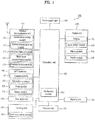
- the mobile terminal 100 includes a wireless communication unit 110, an A/V (audio/video) input unit 120, a user input unit 130, a sensing unit 140, an output unit 150, a memory unit 160, an interface unit 170, a controller unit 180, and a power supply unit 190.
- the mobile terminal 100 can have various components, but it is understood that implementing all of the illustrated components is not required. Greater or fewer components may alternatively be implemented.
- the wireless communication unit 110 can include one or more components that permit wireless communication between the mobile terminal 100 and a wireless communication system or network within which the mobile terminal 100 is located.
- the wireless communication unit 110 can include a broadcast receiving module 111, a mobile communication module 112, a wireless Internet module 113, a short-range communication module 114, and a position-location module 115.
- the broadcast receiving module 111 receives a broadcast signal and/or broadcast associated information from an external broadcast managing server (not shown) via a broadcast channel.
- the broadcast channel may include a satellite channel and a terrestrial channel.
- the broadcast managing server generally refers to a server which generates and transmits the generated broadcast signal and/or broadcast associated information or a server which is provided with a previously generated broadcast signal and/or broadcast associated information and then transmits the provided broadcast signal or information to the mobile terminal 100.
- the transmitted broadcast signal may be implemented as a television (TV) broadcast signal, a radio broadcast signal, and a data broadcast signal.
- the transmitted broadcast signal may be combined with a TV or radio broadcast signal.
- the broadcast associated information can include information associated with a broadcast channel, a broadcast program, and a broadcast service provider.
- the broadcast associated information can be provided via a mobile communication network, and be received by the mobile communication module 112 via a broadcast signal antenna 116.
- broadcast associated information can be implemented in various forms.
- broadcast associated information may include an electronic program guide (EPG) related to digital multimedia broadcasting (DMB) and electronic service guide (ESG) related to digital video broadcast-handheld (DVB-H).
- EPG electronic program guide
- ESG electronic service guide
- the broadcast receiving module 111 may be configured to receive broadcast signals transmitted from various types of broadcasting systems.
- the broadcasting systems can include digital multimedia broadcasting-terrestrial (DMB-T), digital multimedia broadcasting-satellite (DMB-S), digital video broadcast-handheld (DVB-H), media forward link only (MediaFLO®) and integrated services digital broadcast-terrestrial (ISDB-T). Greater or fewer broadcasting systems can be received by the broadcast receiving module 111.
- DMB-T digital multimedia broadcasting-terrestrial
- DMB-S digital multimedia broadcasting-satellite
- DVD-H digital video broadcast-handheld
- MediaFLO® media forward link only
- ISDB-T integrated services digital broadcast-terrestrial
- the broadcast signal and/or broadcast associated information received by the broadcast receiving module 111 may be stored in a storage device, such as the memory unit 160.
- the mobile communication module 112 transmits and receives wireless signals between one or more network entities (e.g., base station, external terminal, and server) via the broadcast signal antenna 116.
- the transmitted and received wireless signals may represent audio, video, and data signals according to text or multimedia message transmissions.
- the wireless Internet module 113 supports Internet access for the mobile terminal 100.
- the wireless Internet module 113 may be internally or externally coupled to the mobile terminal 100.
- the wireless Internet technology supported by the wireless Internet module 113 can include Wireless LAN (WLAN), Wireless Fidelity (Wi-FiTM), Wibro (Wireless broadband), World Interoperability for Microwave Access (WiMAX), and High Speed Downlink Packet Access (HSDPA).
- the short-range communication module 114 facilitates relatively short-range communications. Suitable technologies for implementing the short-range communication module 114 can include radio frequency identification (RFID), infrared data association (IrDA), ultra-wideband (UWB), Bluetooth® and ZigBee®.
- RFID radio frequency identification
- IrDA infrared data association
- UWB ultra-wideband
- Bluetooth® ZigBee®
- the position information module 115 is a module for identifying or otherwise obtaining a position of the mobile terminal.
- the position information module 115 can acquire position information using a global navigation satellite system (GNSS).
- GNSS refers to radio navigation satellite systems that orbit the earth and transmit reference signals so that the location of certain types of radio navigation receivers on the earth's surface can be determined or approximated.
- GNSS includes a global positioning system (GPS) managed by the USA, Galileo managed by Europe, global orbiting navigational satellite system (GLONASS) managed by Russia, COMPASS managed by China, and quasi-zenith satellite system (QZSS) managed by Japan.
- GPS global positioning system
- GLONASS global orbiting navigational satellite system
- QZSS quasi-zenith satellite system
- the position information module 115 may be a GPS (Global Positioning System) module.
- the GPS module 115 can calculate information on distances between one point (object) and at least three satellites, information on the time when the distance information is measured, and use the obtained distance information to triangulate three-dimensional position information on the point (object) according to latitude, longitude and altitude at a predetermined time.
- a method of calculating position and time information using three satellites and correcting the calculated position and time information using another satellite can also be used.
- the GPS module 115 continuously calculates the current position in real time and calculates velocity information using the position information.
- the audio/video (A/V) input unit 120 can be configured to provide audio or video signal input to the mobile terminal 100.
- the A/V input unit 120 can include a camera module 121, a microphone module 122, a flash module 123 and a mirror module 124.
- the camera module 121 can receive and process image frames of still pictures (e.g., photographs) obtained by an image sensor when the mobile terminal 100 is in a photographing mode, and alternatively, receive and process moving picture data (e.g., video) when the mobile terminal 100 is in a video call mode.
- the processed image frames can be displayed by the output unit 150, such as a display module 151.
- the image frames processed by the camera module 121 can be stored in the memory unit 160 or can be externally transmitted via the wireless communication unit 110. At least two camera modules 121 can be provided in the mobile terminal 100 depending on the usage environment.
- the microphone module 122 receives an external audio signal while the mobile terminal 100 is in a particular mode, such as a phone call mode, a recording mode and a voice recognition mode.
- the external audio signal is processed and converted into digital audio data.
- the digital audio data is transformed into a format transmittable to a mobile communication base station via the mobile communication module 112 when the mobile terminal 100 is in a call mode.
- the microphone module 122 can include assorted noise removing algorithms to remove noise generated when receiving the external audio signal.
- the flash module 123 can provide lighting in conjunction with the camera module 121 obtaining images of the external environment.
- the mirror module 124 can provide a user with a reflective surface.
- the user input unit 130 generates input data responsive to user manipulation of one or more associated input devices.
- input devices can include a keypad, a dome switch, a touchpad (e.g., static pressure/capacitance), a jog wheel, and a jog switch.
- the sensing unit 140 provides sensing signals for controlling operations of the mobile terminal 100 using status measurements of various aspects of the mobile terminal 100.
- the sensing unit 140 may detect an open/close status of the mobile terminal 100, a relative positioning of components (e.g., a display and keypad) of the mobile terminal 100, a change of position of the mobile terminal 100 or a component of the mobile terminal 100, a presence or absence of user contact with the mobile terminal 100, or an orientation or acceleration/deceleration of the mobile terminal 100.
- the sensing unit 140 may sense whether a sliding portion of the mobile terminal 100 is open or closed. In another example, the sensing unit 140 can sense the presence or absence of power provided by the power supply unit 190, the presence or absence of a coupling or connection between the interface unit 170 and a device external to the mobile terminal 100.
- the sensing unit 140 can include a proximity sensor 141.
- the output unit 150 generates outputs relevant to senses of sight, hearing, and touch.
- the output unit 150 can include the display module 151, an audio output module 152, an alarm module 153, a haptic module 154 and an earphone module 156.
- the display module 151 can be implemented to visually display or output information associated with the mobile terminal 100. For example, if the mobile terminal 100 is operating in a phone call mode, the display module 151 can provide a user interface (UI) or graphical user interface (GUI) which includes information associated with placing, conducting, and terminating a phone call. In another example, if the mobile terminal 100 is in a video call mode or a photographing mode, the display module 151 may additionally or alternatively display images which are associated with the photographing or video call modes, the UI or the GUI.
- UI user interface
- GUI graphical user interface
- the display module 151 may be implemented using one or more display technologies which include a liquid crystal display (LCD), a thin film transistor-liquid crystal display (TFT-LCD), an organic light-emitting diode display (OLED), a flexible display and a three-dimensional (3D) display.
- a transparent display can be implemented using some of the foregoing display technologies in a transparent or optical transmittive type, such as a transparent OLED (TOLED).
- TOLED transparent OLED
- a rear configuration of the display module 151 can be implemented in the optical transmittive type as well. In this configuration, a user can see an object at a rear portion of the mobile terminal 100 via an area occupied by the display module 151.
- At least two display modules 151 can be provided in the mobile terminal 100.
- a plurality of display modules 151 can be arranged on a single face of the mobile terminal 100 spaced apart from each other or built into one body.
- a plurality of display modules 151 can be arranged on different faces of the mobile terminal 100.
- the display module 151 and the sensing unit 140 for detecting a touch action are configured as a mutual layer structure (hereinafter called “touchscreen”)
- the display module 151 can be used as a user input unit 130 as well as an output unit 150.
- the touch sensor can be configured as a touch film, a touch sheet, or a touchpad.
- the touch sensor can be configured to convert a pressure applied to a specific portion of the display module 151 or a variation of a capacitance generated from a specific portion of the display module 151 to an electric input signal. Accordingly, the touch sensor detects a pressure of a touch as well as a touched position or size.
- a touch input is made to the touch sensor, signal(s) corresponding to the touch input is transferred to a touch controller (not shown).
- the touch controller processes the signal(s) and then transfers the processed signal(s) to the controller unit 180. Therefore, the controller unit 180 can determine whether a prescribed portion of the display module 151 has been touched.
- the proximity sensor 141 can be provided to an internal area of the mobile terminal 100 enclosed by the display module 151, such as the touchscreen or around the touchscreen.
- the proximity sensor 141 is a sensor that detects a presence of an object approaching a prescribed detecting surface or an object existing around the proximity sensor 141 using an electromagnetic field strength or infrared ray without mechanical contact.
- the proximity sensor 141 can be more durable and more useful than a contact type sensor.
- the proximity sensor 141 can include a transmittive photoelectric sensor, a direct reflective photoelectric sensor, a mirror reflective photoelectric sensor, a radio frequency oscillation proximity sensor, an electrostatic capacity proximity sensor, a magnetic proximity sensor, or an infrared proximity sensor. If the touchscreen includes the electrostatic capacity proximity sensor, the touchscreen is configured to detect the proximity of a pointer according to a variation in an electric field formed by the proximity of the pointer to the touchscreen. Accordingly, the touchscreen or touch sensor can be classified as the proximity sensor 141.
- proximity touch An action when a pointer approaches without contacting the touchscreen so the pointer is recognized as being located on the touchscreen is defined as "proximity touch.”
- contact touch An action when a pointer actually touches the touchscreen is defined as “contact touch.”
- the meaning of the position on the touchscreen proximity-touched by the pointer means the position of the pointer which vertically opposes the touchscreen when the pointer performs the proximity touch.
- the proximity sensor 141 detects a proximity touch and a proximity touch pattern (e.g., a proximity touch distance, a proximity touch duration, a proximity touch position, or a proximity touch shift state.). Information corresponding to the detected proximity touch action and the detected proximity touch pattern can be displayed on the touchscreen.
- a proximity touch pattern e.g., a proximity touch distance, a proximity touch duration, a proximity touch position, or a proximity touch shift state.
- the audio output module 152 functions in various modes including a call-receiving mode, a call-placing mode, a recording mode, a voice recognition mode, and a broadcast reception mode in order to output audio data which is received from the wireless communication unit 110 or stored in the memory unit 160.
- the audio output module 152 outputs audio relating to a particular function (e.g., call received, message received).
- the audio output module 152 can be implemented individually or by using one or more speakers, buzzers, and other audio producing devices.
- the alarm module 153 outputs a signal for announcing an occurrence of a particular event associated with the mobile terminal 100.
- Examples of the announced events can include a call received event, a message received event and a touch input received event.
- the alarm module 153 can output a signal for announcing the event occurrence by way of vibration as well as via a video or audio signal.
- the video or audio signal can be output via the display module 151 or the audio output module 152.
- the display module 151 or the audio output module 152 can be regarded as a part of the alarm module 153.
- the haptic module 154 generates various tactile effects that can be sensed by a user. Vibration is a representative tactile effect generated by the haptic module 154. Strength and pattern of the vibration generated by the haptic module 154 can be controlled. For example, different vibrations can be output simultaneously or sequentially.
- the haptic module 154 can generate various tactile effects as well as the vibration. For example, the haptic module 154 generates an effect attributed to the arrangement of pins vertically moving against a contact skin surface, an effect attributed to the injection/suction power of air though an injection/suction hole, an effect attributed to skimming over a skin surface, an effect attributed to the contact with an electrode, an effect attributed to electrostatic force, or an effect attributed to the representation of hold/cold sense using an endothermic or exothermic device.
- the haptic module 154 can be implemented to enable a user to sense the tactile effect through a muscle sense of a finger or an arm as well as to transfer the tactile effect through direct contact. At least two haptic modules 154 can be provided in the mobile terminal 100.
- the audio output module 152 can output sound through an earphone jack 156.
- the user can connect earphones to the earphone jack 156 and hear the output sound.
- the memory unit 160 can be used to store various types of data to support processing, control, and storage requirements of the mobile terminal 100. Examples of such stored data include program instructions for applications operating on the mobile terminal 100, contact data, phonebook data, messages, audio, still pictures, and moving pictures.
- the memory unit 160 can also store a recent use history or a cumulative use frequency of each data (e.g., use frequency for each phonebook, each message or each multimedia).
- data for various patterns of vibration and/or sound output can be stored in the memory unit 160 when a touch input to the touchscreen is sensed.
- the memory unit 160 may be implemented using any type or combination of suitable volatile and non-volatile memory or storage devices including hard disk, random access memory (RAM), static random access memory (SRAM), electrically erasable programmable read-only memory (EEPROM), erasable programmable read-only memory (EPROM), programmable read-only memory (PROM), read-only memory (ROM), magnetic memory, flash memory, magnetic or optical disk, multimedia card micro type memory, card-type memory (e.g., SD memory, XD memory), or other similar memory or data storage device. Further, the mobile terminal 100 can operate via a web storage entity for performing a storage function of the memory unit 160 on the Internet.
- RAM random access memory
- SRAM static random access memory
- EEPROM electrically erasable programmable read-only memory
- EPROM erasable programmable read-only memory
- PROM programmable read-only memory
- ROM read-only memory
- magnetic memory flash memory
- flash memory magnetic or optical disk
- multimedia card micro type memory
- the interface unit 170 can be implemented to couple the mobile terminal 100 with external devices.
- the interface unit 170 receives data from the external devices or is supplied with power and then transfers the data or power to the respective elements of the mobile terminal 100 or enables data within the mobile terminal 100 to be transferred to the external devices.
- the interface unit 170 may be configured using a wired/wireless headset port, an external charger port, a wired/wireless data port, a memory card port, a port for coupling to a device having an identity module, audio input/output ports, video input/output ports, and an earphone port.
- the identity module (not shown) can be an integrated circuit for storing various types of information for authenticating a use authority of the mobile terminal 100 and can include a User Identify Module (UIM), Subscriber Identify Module (SIM), and Universal Subscriber Identity Module (USIM).
- a device having the identity module (hereinafter called "identity device") can be manufactured as a smart card. Therefore, the identity device can be connected to the mobile terminal 100 via a corresponding port.
- the interface unit 170 When the mobile terminal 100 is connected to an external cradle, the interface unit 170 provides a passage for supplying power to the mobile terminal 100 from the external cradle or a passage for delivering various command signals input by a user via the external cradle, to the mobile terminal 100.
- Each of the delivered command signals input via the external cradle or the supplied power can signal that the mobile terminal 100 has been correctly loaded in the external cradle.
- the controller unit 180 controls the overall operations of the mobile terminal 100. For example, the controller unit 180 controls and processes voice calls, data communications, and video calls.
- the controller unit 180 may include a multimedia module 181 that provides multimedia playback.
- the multimedia module 181 may be configured as part of the controller unit 180, or implemented as a separate component.
- the controller unit 180 can perform a pattern recognition process for recognizing characters of a written input and images of a picture drawing input carried out on the touchscreen.
- the power supply unit 190 provides power used by the various components of the mobile terminal 100.
- the provided power may be provided internally or externally to the mobile terminal 100.
- Various embodiments described herein may be implemented in a computer-readable medium using, for example, computer software, hardware, or some combination thereof.
- the embodiments described herein may be implemented individually or combined within one or more application specific integrated circuits (ASICs), digital signal processors (DSPs), digital signal processing devices (DSPDs), programmable logic devices (PLDs), field programmable gate arrays (FPGAs), processors, controllers, microcontrollers, microprocessors, or other electronic units designed to perform the functions described herein.
- ASICs application specific integrated circuits
- DSPs digital signal processors
- DSPDs digital signal processing devices
- PLDs programmable logic devices
- FPGAs field programmable gate arrays
- processors controllers, microcontrollers, microprocessors, or other electronic units designed to perform the functions described herein.
- controller unit 180 may also be implemented by the controller unit 180.
- the embodiments described herein may be implemented with separate software modules, such as procedures and functions, each of which perform one or more of the functions and operations described herein.
- the software codes can be implemented with a software application written in any suitable programming language and may be stored in memory such as the memory unit 160, and executed by a controller or processor, such as the controller unit 180.
- FIG. 2A is a perspective diagram of a front side of the mobile terminal 100 according to an embodiment of the present invention.
- the mobile terminal 100 is configured to have a bar-type terminal body.
- the mobile terminal 100 may be implemented in a variety of different configurations. Examples of such configurations include a folder-type, a slide-type, a rotational-type, a swing-type and combinations thereof.
- the remainder of the disclosure will discuss the mobile terminal 100 directed to the bar-type terminal body. However such teachings apply equally to other types of mobile terminals.
- the mobile terminal 100 includes a case (casing, housing, cover, etc.) configuring an exterior thereof.
- the case can be divided into a front case 101 and a rear case 102.
- Various electric or electronic parts are loaded in a space provided between the front case 101 and rear case 102.
- at least one middle case can be additionally provided between the front case 101 and rear case 102.
- the cases 101 and 102 can be formed by injection molding of synthetic resin or can be formed of metal substances such as stainless steel or titanium.
- the front case 101 of the mobile terminal 100 can include the display module 151, the audio output unit 152, a camera module 121, user input units 131 and 132, the microphone module 122, or the interface unit 170.
- the display module 151 occupies most of a main face of the front case 101.
- the audio output unit 151 and the camera module 121 are provided on an area adjacent to one of two end portions of the display module 151, while the user input unit 131 and the microphone module 122 are provided to another area adjacent to the other end portion of the display module 151.
- the user input unit 132 and the interface unit 170 can be provided on lateral sides of the front case 101 and rear case 102.
- the input unit 130 is manipulated to receive a command for controlling an operation of the mobile terminal 100.
- the input unit 130 can include a plurality of manipulating units 131 and 132.
- the manipulating units 131 and 132 can be named a manipulating portion and may adopt any mechanism of a tactile manner that enables a user to perform a manipulation action by sensing a tactile feedback.
- Content input by the first manipulating unit 131 or second manipulating unit 132 can be diversely set. For instance, commands such as start, end or scroll can be input to the first manipulating unit 131. On the other hand, commands directed to adjusting a volume of sound outputting from the audio output unit 152 or switching to a touch recognizing mode of the display module 151 can be input to the second manipulating unit 132.
- FIG. 2B is a perspective diagram of a rear side of the mobile terminal 100 shown in FIG. 4 according to an embodiment of the present invention.
- a camera module 121' can be additionally provided to a backside of the mobile terminal 100, and more particularly, to the rear case 102.
- the camera module 121' has a photographing direction that is substantially opposite to that of the camera module 121 shown in FIG. 3A and may have a different number of pixels to provide a different resolution from that of the camera module 121.
- the camera module 121 can have enough resolution to capture and transmit a picture of a user's face for a video call, while the camera module 121' has a higher resolution for capturing a general subject for photography without transmitting the captured subject.
- Each of the camera modules 121 and 121' can be installed in the mobile terminal 100 to be rotated open or popped open.
- the flash module 123 and the mirror module 124 are additionally provided adjacent to the camera module 121'.
- the flash module 123 projects light toward a subject in case of photographing the subject using the camera module 121'.
- the mirror module 124 enables the user to view user's face reflected by the mirror module 124.
- An additional audio output unit 152' can be provided to the backside of the mobile terminal 100.
- the additional audio output unit 152' can implement a stereo function together with the audio output unit 152 shown in FIG. 3A and may be used to implement a speakerphone mode when the mobile terminal 100 is configured in the phone call mode.
- the broadcast signal antenna 116 can be provided to the lateral side of the mobile terminal 100 to provide further communication capabilities to the mobile terminal 100.
- the broadcast signal antenna 116 can be constructed as a portion of the broadcast receiving module 111 shown in FIG. 1 . Additionally, the broadcast signal antenna 116 can be configured to be retractable in the mobile terminal 100.
- the power supply unit 190 for supplying power to the mobile terminal 100 can be configured to be built within the mobile terminal 100. Alternatively, the power supply unit 190 can be configured to be detachably connected to the mobile terminal 100.
- a touchpad 135 for detecting a touch can be additionally provided to the rear case 102.
- the touchpad 135 can be configured in a light transmittive type like the display module 151.
- the display module 151 is configured to output visual information from its both faces, it can recognize the visual information via the touchpad 135 as well.
- the information output from both of the faces can be entirely controlled by the touchpad 135.
- a display is further provided to the touchpad 135 so that a touchscreen can be provided to the rear case 102 as well.
- the touchpad 135 is activated by interconnecting with the display module 151 of the front case 101.
- the touchpad 135 can be provided in rear of the display module 151 in parallel.
- the touchpad 135 can have a size equal to or smaller than that of the display module 151.
- FIG. 3 is a flowchart for a method of controlling a mobile terminal according to an embodiment of the present invention.
- the controller 180 can control a lock screen to be displayed on the display module 151 [S31].
- Icons of the executed menus can be displayed on the lock screen in the order of the corresponding menu being executed.
- the icons can coexist in the lock screen irrespective of whether the use of the corresponding menu is restricted or non-restricted [S32].
- the controller 180 determines whether the selected icon is a restricted use icon or a non-restricted use icon [S34]. In other words, the controller 180 determines whether a password would be required to access the selected menu icon.
- the controller 180 can control the locked state to be directly released without performing a user authentication procedure. Accordingly, the controller 180 releases the locked state [S35]. Alternatively, if the music play menu icon is designated as a restricted use icon, the user authentication procedure would be performed.
- the controller 180 determines whether the entered password is correct [S36].
- the password may be preset and stored in the mobile terminal 100. Accordingly, a password can be entered to determine whether it matches the preset password and, therefore, complete the user authentication procedure.
- the controller 180 can control the locked state to be released.
- the controller 180 can control the locked state not to be released [S37].
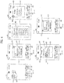
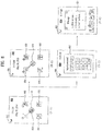
- FIG. 4 and FIG. 5 are diagrams of display screen configurations for implementing a method of controlling a mobile terminal according to an embodiment of the present invention.
- the controller 180 of the mobile terminal 100 can control a standby image to be displayed on a touchscreen 400.
- a plurality of menus or applications can be executed in the mobile terminal 100 and at least one or more menu icons corresponding to a plurality of the menus can be displayed on the standby image.
- Various menu icons including a music play menu icon 410, a message menu icon 420, a calendar menu icon 430 and an Internet browser menu icon 440 can be displayed on the standby image.
- 'menu', 'application' and 'function' of the mobile terminal can be regarded as being equivalent to each other in a sense of executing a corresponding function. Therefore, in the following description, each of the terms 'menu', 'application' and 'function' can indicate the same meaning in use.
- a setting to restrict use of the mobile terminal 100 can be performed individually on each of the menus executable by the mobile terminal 100. As such, a corresponding menu can only be executed if a prescribed user authentication procedure is performed.
- the prescribed user authentication restricts non-authorized users in using the corresponding menu except an authorized user in order to protect the authorized user's privacy or prevent unauthorized use of the mobile terminal 100.
- the terminal user can set a user restriction for each individual menu through an appropriate manipulation of the user input unit 130 of the mobile terminal 100.
- the corresponding details shall be omitted from the following description.
- restriction indicators 421 and 441 can be displayed relative to the message menu icon 420 and the Internet browser menu icon 440, respectively, to inform the terminal user that the corresponding menu is restricted.
- a menu for setting the user restrictions can be executed in the mobile terminal 100.
- the music play menu icon 410 can be touched and selected from the touchscreen 400. Since the music play menu is not restricted, the controller can control a music play menu to be executed in the mobile terminal 100 without performing a user authentication procedure.
- the controller 180 can display on the touchscreen 400 a music play window 415 in response to the music play menu icon 410 being selected.
- a close icon 412 for closing the music play window 415 can be included in the music play window 415.
- the message menu icon 420 can be touched and selected from the touchscreen 400.
- the controller 180 can control a user authentication window 405 for the user authentication procedure to be displayed since the message menu is restricted. As such, a user authentication procedure can be performed.
- the controller 180 displays on the touchscreen 400 a user authentication window 405.
- the user authentication window 405 can be presented in various ways for receiving user authentication information.
- the terminal user inputs a preset password (e.g., user authentication information) via the user authentication window 405, the user authentication procedure can be performed.
- a preset password e.g., user authentication information
- the controller 180 can execute the message menu while executing the music play menu.
- the multitasking of the music play menu and the message menu can be performed in the mobile terminal 100.
- the controller 180 can control a message window 425 to be displayed on the touchscreen 400.
- the controller 180 can control a multitasking icon 423 to be displayed on the message window 425.
- the controller 180 can control a multitasking list 407 for listing currently executed menus to be displayed on the touchscreen 400 if the multitasking icon 423 is selected.
- icons of the executed menus in multitasking e.g., the music play menu icon 410 and the message menu icon 420 can be displayed on the multitasking list 407.
- the music play menu icon 410 can be touched and selected from the multitasking list 407 to switch from the message window 425 to the music play window 415.
- the controller 180 keeps performing the multitasking on the music play menu and the message menu and is also able to control the music play window 415 to be displayed on the touchscreen 400.
- the controller 180 can control the multitasking icon 413 to be displayed on the music play window 415 as well.
- the 'locked state' means a state that a partially restricted touch gesture can be recognized only while partially restricted information is just displayed on the touchscreen 400 for the prevention of malfunction (or incorrect manipulation) and the protection of terminal user's privacy.
- the controller 180 can control the mobile terminal 100 to enter the locked state.
- the icons of the menus can coexist while executing a multitasking operation, that is, the music play menu icon 410 and the message menu icon 420 can be simultaneously displayed on the lock screen via the touchscreen 400.
- the music play menu icon 410 can be displayed together with a corresponding path 416 and a corresponding destination 417. Additionally, the message menu icon 420 can be displayed together with a corresponding path 426 and a corresponding destination 427.
- the music play menu icon 410 Since the music play menu icon 410 does not have a restriction indicator displayed nearby, the music play menu icon 410 is one of the non-restricted menus on the lock screen. In contrast, as a restriction indicator is displayed on the message menu icon 420, the message menu icon 420 is one of the restricted menus on the lock screen.
- the controller 180 can control where on the touchscreen 400 a touch gesture could be recognized or detected. For example, a touch gesture performed on each of the music play menu icon 410 and the message menu icon 420 can be detected to release the locked state.
- a touch gesture can be performed by touching and dragging the music play menu icon 410 along the corresponding path 416 to the corresponding destination 417.
- the controller 180 can control the lock screen to be removed from the touchscreen 400 and instead display the music play window 415 when the locked state is released.
- the message menu icon 420 can be selected to release the locked state in a following manner.
- a touch gesture can be performed by touching and dragging the message menu icon 420 along the corresponding path 426 to the corresponding destination 427.
- the controller 180 can control the user authentication window 405 to be displayed to execute the user authentication procedure. Upon detecting the touched and dragged message menu icon 420 on the corresponding destination 427, the user authentication procedure can be performed. Accordingly, a password can be entered via the user authentication window 405.
- the controller 180 can control the lock screen to disappear from the touchscreen 400 and instead display the message window 425 when the locked state is released using the message menu icon 420.
- menu icons being displayed on the lock screen during a multitasking operation are non-limiting.
- menu icons previously set as "favorite" menus by a terminal user can be displayed on the lock screen. If one of the favorite menu icons is selected, the locked sate can be released. Accordingly, the corresponding menu of the selected favorite menu icon can be displayed on the touchscreen 400 instead of the lock screen.
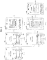
- FIG. 6 is a diagram of display screen configurations for implementing a method of controlling the mobile terminal 100 according to an embodiment of the present invention. For example, various types of lock screens can be displayed on the touchscreen 400 of the mobile terminal 100.
- restricted use icons and non-restricted use icons can coexist on different portions of the lock screen.
- a restricted use menu region 408 for restricted use icons can be allocated on the lock screen.
- the restricted use icons 420 and 440 can be displayed separately from the non-restricted use icons 410 and 430 such that the restricted use menus can be displayed in the restricted use menu region 408.
- the non-restricted use icons 410 and 430 can be displayed outside the restricted use menu region 408.
- the mobile terminal 100 can be released from the locked state using an icon being displayed on the lock screen.
- a common portion of the touchscreen 400 can be used to execute each of the menu icons displayed on the lock screen.
- the menu icons displayed on the lock screen can be configured to have a common destination 470.
- a corresponding path of the menu icon can be omitted from being displayed on the lock screen.
- each of the menu icons displayed on the lock screen can be touched and dragged to the common destination 470 for execution regardless of the type of restriction corresponding to the menu icon.
- corresponding paths can be displayed depending on the type of restriction of the menu icon.
- corresponding paths 416 and 436 of the non-restricted use icons 410 and 430 can be displayed on the lock screen.
- the restricted use icons 420 and 440 can be displayed on the lock screen without corresponding paths for execution.
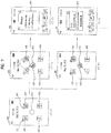
- FIG. 7 and FIG. 8 are diagrams of display screen configurations for implementing a method of controlling a mobile terminal according to an embodiment of the present invention.
- the restricted use icons 420 and 440, the non-restricted use icons 410 and 430, and the common destination 470 can be displayed on the lock screen of the touchscreen 400.
- selecting a restricted use icon using a predetermined motion on the touchscreen 400 can release the mobile terminal 100 from the locked state.
- the message menu icon 420 noted as a restricted use icon via the restricted indicator 421, can be touched and dragged to the common destination 470, for example.
- the corresponding touch and drag can be performed along a predetermined pattern or trace as a form of completing the user authentication procedure.
- the process of releasing the mobile terminal 100 from the locked state by selecting the message menu icon 420 can be reduced to a single touch gesture (e.g., a single touch stroke) performed on the touchscreen 400.
- the combination of a touch and drag input in a predetermined path on the touchscreen 400 and the user authentication procedure to be executed simultaneously with respect to the touch and drag input allows the locked state release to be more efficient and convenient to a user.
- FIG. 7 (7-2) exemplarily shows that a predetermined touch pattern to execute a user authentication procedure is performed such that the touch pattern includes a circle-shaped rotation in a counterclockwise direction on the touchscreen 400.
- the controller 180 determines whether the message menu icon 420 has been touched and dragged to the common destination 470 and also determines whether the message menu icon 420 has been correctly touched and dragged along the predetermined touch pattern.
- the controller 180 can control the locked state to be released if there no error in performing the predetermined touch pattern is detected. As mentioned in the foregoing description, since the locked state is released using the message menu icon 420, the controller 180 can control the message window 425 to be displayed on the touchscreen 400 by removing the lock screen from the touchscreen 400.
- the music play menu icon 410 can be touched and dragged to the common destination 470. Since the music play menu icon 410 is a non-restricted use icon, the music play menu icon 410 can be merely dragged from its original position to the common destination 470 since no user authentication procedure is to be performed. That is, a non-restricted use icon does not need to follow a predetermined pattern on the touchscreen 400.
- the controller 180 determines whether the music play menu icon 410 has been touched and dragged to the common destination 470. If there is no problem as a result of the determination, referring to FIG. 7 (7-5), the controller 180 can control the locked state to be released. As mentioned in the foregoing description, since the locked state is released using the music play menu icon 410, the controller 180 can control the music play window 415 to be displayed on the touchscreen 400 by removing the lock screen from the touchscreen 400.
- the controller 180 can control the locked state not to be released.
- the lock screen may be removed in response to a non-predetermined pattern or trace.
- the message menu icon 420 as a restricted use icon is touched and dragged to the common destination 470 on the lock screen of the touchscreen 400 without following a predetermined touch trace or pattern.
- the controller 180 can control the locked state not to be released in the mobile terminal 100 by having the touched and dragged message menu icon 420 return to its original position.
- the controller 180 can control the user authentication window 405 to be displayed on the touchscreen 400 for the user authentication procedure to be performed.
- the controller 180 can control the user authentication procedure to proceed.
- the controller 180 can control the locked state to be released.
- FIG. 9 is a diagram of display screen configurations for implementing a method of controlling a mobile terminal according to an embodiment of the present invention.
- the restricted use icons 420 and 440 and the non-restricted use icons 410 and 430 are displayed on the lock screen of the touchscreen 400.
- the corresponding destinations 417, 427, 437 and 447 can be displayed on the lock screen to correspond to the displayed icons 410, 420, 430 and 440, respectively.
- touch paths 416 and 436 can be displayed on the lock screen of the touchscreen 400 to correspond to the non-restricted use icons 410 and 430, respectively.
- the message menu icon 420 as a restricted use icon is selected then touched and dragged to the corresponding destination 427.
- the touch and drag operation can be performed along a predetermined touch pattern or trace for performing a user authentication procedure.
- the combination of a touch and drag input in a predetermined path on the touchscreen 400 being performed simultaneously with the user authentication procedure can be reduced to a single touch gesture (e.g., a single touch stroke).
- FIG. 9 (9-2) exemplarily shows that the touch pattern on the touchscreen 400 for the user authentication procedure can be a circular rotation in a counterclockwise direction, for example.
- the controller 180 determines whether the message menu icon 420 has been touched and dragged to the corresponding destination 427 and also determines whether the message menu icon 420 has been touched and dragged along the predetermined touch pattern.
- the controller 180 can control the locked state to be released.
- the locked state can be released via the message menu icon 420 without following a predetermined pattern or trace by executing the user authentication procedure via the user authentication window 405.
- the message menu icon 420 as the restricted use icon can be touched and dragged to the corresponding destination 427 on the lock screen of the touchscreen 400 without following a preset touch trace ( FIG. 9 (9-4)).
- the controller 180 can control the user authentication window 405 to be displayed as an additional user authentication procedure on the touchscreen 400 upon detecting the preset touch trace.
- the terminal user may enter the user authentication procedure via the user authentication window 405 upon a touch and drag input without a preset touch trace being detected.
- the controller 180 can control the user authentication procedure to proceed. If the preset password is input to the user authentication window 405, the controller 180 can control the locked state to be released ( FIG. 9 (9-3)).
- the mobile terminal when the restricted use icon 420 is touched and dragged to the corresponding destination along the preset touch trace on the lock screen, the mobile terminal is released from the locked state.
- the corresponding destination for the restricted use icon may not exist on the touchscreen 400.
- the restricted use icon is touched and dragged on the lock screen along the preset touch trace, it can configure the mobile terminal to be released from the locked state regardless of the restricted use icon not arriving at any particular destination icon or portion of the touchscreen 400.
- the locked screen when the mobile terminal is released from the locked state, the locked screen is removed from the touchscreen 400 and an image about the corresponding menu of the touched and dragged restricted use icon can be displayed.
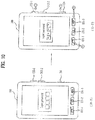
- a soft keypad for inputting a prescribed password can be provided simultaneously with the user authentication window 405 described with reference to FIG. 4 (4-3). Yet, the soft keypad is optionally provided to the user authentication window 405. In the following description, the user authentication window without the soft keypad for the password input is explained with reference to FIG. 10 .
- FIG. 10 is a diagram of a front side of a mobile terminal according to an embodiment of the present invention. Referring to FIG. 10 (10-1), a soft keypad for a password input may not be displayed on the user authentication window 405 for the user authentication procedure.
- hardware key buttons 131-1 to 131-3, 132-1, 132-3 also referred to herein as "hardware key buttons" and 134 provided to the housing of the mobile terminal 100 can be used for the password input.
- the hardware key buttons may be separate from a keypad provided to the mobile terminal 100.
- the hardware key buttons can each operate for unique functions. If the user authentication window 405 is displayed on the touchscreen 400, the hardware key buttons can be used for the password input.
- the hardware key buttons can be pressed entirely or in part in preset order.
- the partial or entire manipulation of the hardware key buttons according to the preset order can correspond to the input of the preset password for the user authentication procedure.
- FIG. 10 (10-2) exemplarily shows that the hardware key buttons are sequentially pressed in order to input the preset password.
- the hardware key buttons can be repeatedly pressed at least twice.
- the hardware key buttons can be understood as one of various user authentication information input means that can be implemented in the mobile terminal 100.
- the restricted use icons can be continually displayed on the lock screen. In another embodiment, while the mobile terminal is in the locked state, the restricted use icons may not be displayed continually on the lock screen. This is further explained with reference to FIGs. 11 to 13 as follows.
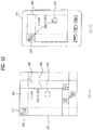
- FIGs. 11 to 13 are diagrams of a front side of a mobile terminal according to an embodiment of the present invention, in which a virtual lock screen domain for the mobile terminal is shown.
- the virtual lock screen domain can include a main display region 500 and at least one subdisplay regions 610 to 680.
- FIG. 11 (11-1) exemplarily shows that the subdisplay regions can be arranged around the main display region 500.
- the main display region 500 is the region basically displayed on the touchscreen 400 when the mobile terminal 100 enters the locked state.
- the non-restricted use icons 410 and 430 can exist in the main display region 500 ( FIG. 11 (11-1)).
- the region displayed on the touchscreen 400 ( FIG. 11 (11-2)) is represented as a display frame 600 ( FIG. 11 (11-1)).
- the subdisplay regions 610 to 680 are the regions that can be displayed when a touch and drag is performed on the touchscreen 400 in a prescribed direction.
- a subdisplay region corresponding to the touch and drag direction among the subdisplay regions 610 to 680 can be displayed.
- the subdisplay regions 610 to 680 can be hidden instead of being displayed until the touch and drag is performed on the touchscreen 400. Accordingly, the subdisplay regions 610 to 680 can be understood as hidden regions (or hidden areas) of the touchscreen 400.
- a touch and drag input can be performed in a direction "A" or a direction "B.”
- the display frame 600 can be shifted in the opposite of the direction "A" within a virtual lock screen domain.
- the shifted display frame 600 can be positioned by occupying a whole part of the subdisplay region 660 located at a bottom portion of the virtual screen domain and a portion of the main display region 500, for example.
- the virtual lock screen domain slides to simultaneously display the bottom subdisplay region 660 and the main display region 500 corresponding to the display frame 600 having been shifted in an opposite direction of the direction "A." Therefore, the Internet browser menu icon 440 of the restricted use icon positioned within the bottom subdisplay region 660 can be displayed on the touchscreen 400.
- the display frame 600 can be shifted in an opposite direction of the direction "B" in the virtual lock screen domain.
- the shifted display frame 600 can be positioned by occupying a subdisplay region 610, a portion of the subdisplay region 680, a portion of the display region 620 and a portion of the main display region 500 in the virtual screen domain.
- the virtual lock screen domain when the mobile terminal 100 is in the locked state, the virtual lock screen domain can be repositioned to move in a manner that the subdisplay region 610, the subdisplay region 680, the subdisplay region 620 and the main display region 500, which correspond to the display frame 600 having been shifted in the direction "B", can be displayed simultaneously. Therefore, the message menu icon 420 of the restricted use icon situated in the subdisplay region 610 can be displayed on the touchscreen 400.
- a terminal user recognizes that the Internet browser menu icon 440 is positioned within the bottom subdisplay region 660 among the subdisplay regions 610 to 680, and then performs a touch and drag input on the touchscreen 400 in the direction "A" to enable the bottom subdisplay region 660 to be displayed on the touchscreen 400.
- the same can be said when a touch and drag input on the touchscreen 400 in the direction "B" enables at least the subdisplay region 610 to be displayed on the touchscreen 400.
- This type of user action can be a form of performing the user authentication procedure.
- the controller 180 can control the mobile terminal 100 to be released from the locked state.
- the lock screen disappears from the touchscreen 400 and an image about the corresponding menu of the touched and dragged menu icon can be displayed (not shown).
- the controller 180 can control the mobile terminal 100 to be released from the locked state only if a menu icon on the touchscreen 400 is touched and dragged to the common destination 470 along the preset touch trace in order to perform the user authentication procedure.
- the controller 180 can control the display frame 600 to return to its original position corresponding to the main display region 500. In particular, if a prescribed time passes after the touch and drag in the direction "A" or direction "B" on the touchscreen 400, the controller 180 can control the main display region 500 to be displayed again on the touchscreen 400.
- FIG. 14 is a diagram of display screen configurations for implementing a method of controlling a mobile terminal according to an embodiment of the present invention.
- the controller 180 can control the subdisplay region 660 to appear on the touchscreen 400 in a manner that the subdisplay region 660 slides over the main display region 500 only in response to the touch and drag input in the direction "A.”
- the mobile terminal 100 is released from the locked state.
- a touch and drag input can be performed on the touchscreen 400 in the direction "B," when only the main display region 500 is displayed on the touchscreen 400.
- the controller 180 can control the subdisplay region 610 to appear on the touchscreen 400 in a manner that the subdisplay region 610 slides over the main display region 500 only in response to the touch and drag input in the direction "B.”
- a mobile terminal in a locked state can be unlocked while considering a convenience to a user.
- a user manipulation for a mobile terminal unlocking procedure and a user manipulation for a user authentication procedure are systemized together and can be then performed in the mobile terminal. Therefore, the present disclosure facilitates the lock release.
- the present disclosure provides various lock release scenarios for a mobile terminal, whereby the lock release scenario appropriately selected for a terminal user from the various lock release scenarios can be applied to the mobile terminal.
- the above-described methods can be implemented in a program recorded medium as a computer-readable media.
- the computer-readable media include all kinds of recording devices in which data readable by a computer system are stored.
- the computer-readable media can include ROM, RAM, CD-ROM, magnetic tapes, floppy discs, optical data storage devices, programmable code or carrier-wave type implementations (e.g., transmission via Internet).
- the computer can include the controller 180 of the mobile terminal.
Landscapes
- Engineering & Computer Science (AREA)
- Human Computer Interaction (AREA)
- Computer Networks & Wireless Communication (AREA)
- Signal Processing (AREA)
- Theoretical Computer Science (AREA)
- Computer Security & Cryptography (AREA)
- General Engineering & Computer Science (AREA)
- Physics & Mathematics (AREA)
- General Physics & Mathematics (AREA)
- Computer Hardware Design (AREA)
- Software Systems (AREA)
- Telephone Function (AREA)
- User Interface Of Digital Computer (AREA)
Description
- The present disclosure relates to a mobile terminal, and more particularly, to a mobile terminal and controlling method thereof.
- A mobile terminal is a device which may be configured to perform various functions. Examples of such functions include data and voice communications, capturing images and video via a camera, recording audio, playing music files and outputting music via a speaker system, and displaying images and video on a display. Some terminals include additional functionality which supports game playing, while other terminals are also configured as multimedia players. More recently, mobile terminals have been configured to receive broadcast and multicast signals which permit viewing of content, such as video and television programs.
- Generally, terminals can be classified as mobile terminals and stationary terminals according to a presence or non-presence of mobility. And, the mobile terminals can be further classified into handheld terminals and vehicle mount terminals according to availability for hand-carry.
- There are ongoing efforts to support and increase the functionality of mobile terminals. Such efforts include software and hardware improvements, as well as changes and improvements in the structural components which form the mobile terminal.
- In order to prevent a malfunction or an incorrect manipulation of a mobile terminal or protect a privacy of a terminal user, a lock function can be applied to the mobile terminal. Increasing a terminal user's convenience for unlocking a mobile terminal in a locked state would be desirable.
-
US 2009/222766 A1 may be construed to disclose a mobile terminal comprising a display unit; and a controller configured to selectively display one or more menu icons associated with an object displayed on the display unit, in response to the object being selected, wherein the one or more menu icons have a functional or informational association with the selected object, such that further selection of the menu icons provides additional information about the selected object or establishment of a dynamic relationship between the selected object and the one or more menu icons results in performance of an operation related to the selected object. -
US 2010/178873 A1 may be construed to disclose a mobile terminal and controlling method by which a specific one of various external devices neighboring a mobile terminal may be easily searched and may be connected to the mobile terminal by short-range communication. -
EP 2 128 782 A1 - Accordingly, the present invention is directed to a mobile terminal and controlling method according to the independent claims that substantially obviate one or more problems due to limitations and disadvantages of the related art. Developments are set forth in the dependent claims.
- Preferably, a method of controlling a mobile terminal by displaying simultaneously a plurality of menu icons comprising at least one restricted use icon and at least one non-restricted use icon; performing a user authentication procedure responsive to user selection of the at least one restricted use icon; and unlocking the mobile terminal responsive to user selection of the at least one non-restricted use icon or responsive to completion of the user authentication procedure.
- Preferably, a method of controlling a mobile terminal by displaying a lock screen to indicate the mobile terminal is in a locked state; displaying simultaneously a plurality of menu icons comprising at least one restricted use icon and at least one non-restricted use icon; selecting one of the plurality of menu icons in response to a touch input; determining whether the selected menu icon is the at least one restricted use icon or the at least one non-restricted use icon; performing a user authentication procedure to authenticate a user when the selected menu icon is determined to be the at least one restricted use icon; determining whether the user authentication procedure is complete; and releasing the locked state when the selected menu icon is the at least one non-restricted use icon or the user authentication procedure is complete.
- Preferably, a mobile terminal including a display and a controller configured to display simultaneously on the display a plurality of menu icons comprising at least one restricted use icon and at least one non-restricted use icon, authenticate a user responsive to user selection of the at least one restricted use icon, and unlock the mobile terminal responsive to user selection of the at least one non-restricted use icon or responsive to authentication of the user.
- The accompanying drawings, which are included to provide a further understanding of the invention and are incorporated in and constitute a part of this application, illustrate embodiment(s) of the invention and together with the description serve to explain the principle of the invention. The above and other aspects, features, and advantages of the present invention will become more apparent upon consideration of the following description of preferred embodiments, taken in conjunction with the accompanying drawing figures.
-
FIG. 1 is a block diagram of a mobile terminal according to an embodiment of the present invention. -
FIG. 2A is a front perspective diagram of a mobile terminal according to one embodiment of the present invention. -
FIG. 2B is a rear perspective diagram of a mobile terminal according to one embodiment of the present invention. -
FIG. 3 is a flowchart for a method of controlling a mobile terminal according to an embodiment of the present invention. -
FIGs. 4 to 9 are diagrams of display screen configurations for implementing a method of controlling a mobile terminal according to an embodiment of the present invention. -
FIG. 10 is a diagram of a front side of a mobile terminal according to an embodiment of the present invention. -
FIGs. 11 to 13 are diagram of a front side of a mobile terminal according to an embodiment of the present invention, in which a virtual lock screen domain for the mobile terminal is shown. -
FIG. 14 is a diagram of display screen configurations for implementing a method of controlling a mobile terminal according to an embodiment of the present invention. - In the following detailed description, reference is made to the accompanying drawing figures which form a part hereof, and which show by way of illustration specific embodiments of the invention. It is to be understood by those of ordinary skill in this technological field that other embodiments may be utilized, and structural, electrical, as well as procedural changes may be made without departing from the scope of the present invention. Wherever possible, the same reference numbers will be used throughout the drawings to refer to the same or similar parts. As used herein, the suffixes 'module', 'unit' and 'part' are used for elements in order to facilitate the disclosure only. Therefore, significant meanings or roles are not given to the suffixes themselves and it is understood that the 'module', 'unit' and 'part' can be used together or interchangeably.
- The present disclosure can be applicable to various types of terminals. Examples of such terminals can include mobile terminals, such as mobile phones, user equipment, smart phones, mobile computers, digital broadcast terminals, personal digital assistants, portable multimedia players (PMP) or navigation systems.
- Referring to
FIG. 1 , themobile terminal 100 may refer to an electronic device among a plurality of external electronic devices on a network according to an embodiment of the present invention, which will be described in more detail with reference to the drawings. Themobile terminal 100 can include a cellular phone, a smart phone, a laptop computer, a digital broadcasting terminal, personal digital assistants (PDA), a portable multimedia player (PMP), or a navigation system. - The
mobile terminal 100 according to an embodiment of the present invention includes awireless communication unit 110, an A/V (audio/video)input unit 120, auser input unit 130, asensing unit 140, anoutput unit 150, amemory unit 160, aninterface unit 170, acontroller unit 180, and apower supply unit 190. Themobile terminal 100 can have various components, but it is understood that implementing all of the illustrated components is not required. Greater or fewer components may alternatively be implemented. - The
wireless communication unit 110 can include one or more components that permit wireless communication between themobile terminal 100 and a wireless communication system or network within which themobile terminal 100 is located. For example, thewireless communication unit 110 can include abroadcast receiving module 111, amobile communication module 112, awireless Internet module 113, a short-range communication module 114, and a position-location module 115. - The
broadcast receiving module 111 receives a broadcast signal and/or broadcast associated information from an external broadcast managing server (not shown) via a broadcast channel. The broadcast channel may include a satellite channel and a terrestrial channel. - The broadcast managing server generally refers to a server which generates and transmits the generated broadcast signal and/or broadcast associated information or a server which is provided with a previously generated broadcast signal and/or broadcast associated information and then transmits the provided broadcast signal or information to the
mobile terminal 100. The transmitted broadcast signal may be implemented as a television (TV) broadcast signal, a radio broadcast signal, and a data broadcast signal. The transmitted broadcast signal may be combined with a TV or radio broadcast signal. - The broadcast associated information can include information associated with a broadcast channel, a broadcast program, and a broadcast service provider. The broadcast associated information can be provided via a mobile communication network, and be received by the
mobile communication module 112 via abroadcast signal antenna 116. - The broadcast associated information can be implemented in various forms. For example, broadcast associated information may include an electronic program guide (EPG) related to digital multimedia broadcasting (DMB) and electronic service guide (ESG) related to digital video broadcast-handheld (DVB-H).
- The
broadcast receiving module 111 may be configured to receive broadcast signals transmitted from various types of broadcasting systems. The broadcasting systems can include digital multimedia broadcasting-terrestrial (DMB-T), digital multimedia broadcasting-satellite (DMB-S), digital video broadcast-handheld (DVB-H), media forward link only (MediaFLO®) and integrated services digital broadcast-terrestrial (ISDB-T). Greater or fewer broadcasting systems can be received by thebroadcast receiving module 111. - The broadcast signal and/or broadcast associated information received by the
broadcast receiving module 111 may be stored in a storage device, such as thememory unit 160. - The
mobile communication module 112 transmits and receives wireless signals between one or more network entities (e.g., base station, external terminal, and server) via thebroadcast signal antenna 116. The transmitted and received wireless signals may represent audio, video, and data signals according to text or multimedia message transmissions. - The
wireless Internet module 113 supports Internet access for themobile terminal 100. Thewireless Internet module 113 may be internally or externally coupled to themobile terminal 100. In this case, the wireless Internet technology supported by thewireless Internet module 113 can include Wireless LAN (WLAN), Wireless Fidelity (Wi-Fi™), Wibro (Wireless broadband), World Interoperability for Microwave Access (WiMAX), and High Speed Downlink Packet Access (HSDPA). - The short-
range communication module 114 facilitates relatively short-range communications. Suitable technologies for implementing the short-range communication module 114 can include radio frequency identification (RFID), infrared data association (IrDA), ultra-wideband (UWB), Bluetooth® and ZigBee®. - The
position information module 115 is a module for identifying or otherwise obtaining a position of the mobile terminal. Theposition information module 115 can acquire position information using a global navigation satellite system (GNSS). Here, GNSS refers to radio navigation satellite systems that orbit the earth and transmit reference signals so that the location of certain types of radio navigation receivers on the earth's surface can be determined or approximated. GNSS includes a global positioning system (GPS) managed by the USA, Galileo managed by Europe, global orbiting navigational satellite system (GLONASS) managed by Russia, COMPASS managed by China, and quasi-zenith satellite system (QZSS) managed by Japan. - As one representative example of GNSS, the
position information module 115 may be a GPS (Global Positioning System) module. TheGPS module 115 can calculate information on distances between one point (object) and at least three satellites, information on the time when the distance information is measured, and use the obtained distance information to triangulate three-dimensional position information on the point (object) according to latitude, longitude and altitude at a predetermined time. Moreover, a method of calculating position and time information using three satellites and correcting the calculated position and time information using another satellite can also be used. In addition, theGPS module 115 continuously calculates the current position in real time and calculates velocity information using the position information. - The audio/video (A/V)
input unit 120 can be configured to provide audio or video signal input to themobile terminal 100. The A/V input unit 120 can include acamera module 121, amicrophone module 122, aflash module 123 and amirror module 124. Thecamera module 121 can receive and process image frames of still pictures (e.g., photographs) obtained by an image sensor when themobile terminal 100 is in a photographing mode, and alternatively, receive and process moving picture data (e.g., video) when themobile terminal 100 is in a video call mode. The processed image frames can be displayed by theoutput unit 150, such as adisplay module 151. - The image frames processed by the
camera module 121 can be stored in thememory unit 160 or can be externally transmitted via thewireless communication unit 110. At least twocamera modules 121 can be provided in themobile terminal 100 depending on the usage environment. - The
microphone module 122 receives an external audio signal while themobile terminal 100 is in a particular mode, such as a phone call mode, a recording mode and a voice recognition mode. The external audio signal is processed and converted into digital audio data. The digital audio data is transformed into a format transmittable to a mobile communication base station via themobile communication module 112 when themobile terminal 100 is in a call mode. Themicrophone module 122 can include assorted noise removing algorithms to remove noise generated when receiving the external audio signal. Theflash module 123 can provide lighting in conjunction with thecamera module 121 obtaining images of the external environment. Themirror module 124 can provide a user with a reflective surface. - The
user input unit 130 generates input data responsive to user manipulation of one or more associated input devices. Examples of such input devices can include a keypad, a dome switch, a touchpad (e.g., static pressure/capacitance), a jog wheel, and a jog switch. - The
sensing unit 140 provides sensing signals for controlling operations of themobile terminal 100 using status measurements of various aspects of themobile terminal 100. For example, thesensing unit 140 may detect an open/close status of themobile terminal 100, a relative positioning of components (e.g., a display and keypad) of themobile terminal 100, a change of position of themobile terminal 100 or a component of themobile terminal 100, a presence or absence of user contact with themobile terminal 100, or an orientation or acceleration/deceleration of themobile terminal 100. - In another example, when the
mobile terminal 100 is configured as a slide-type mobile terminal, thesensing unit 140 may sense whether a sliding portion of themobile terminal 100 is open or closed. In another example, thesensing unit 140 can sense the presence or absence of power provided by thepower supply unit 190, the presence or absence of a coupling or connection between theinterface unit 170 and a device external to themobile terminal 100. Thesensing unit 140 can include aproximity sensor 141. - The
output unit 150 generates outputs relevant to senses of sight, hearing, and touch. Theoutput unit 150 can include thedisplay module 151, anaudio output module 152, analarm module 153, ahaptic module 154 and an earphone module 156. - The
display module 151 can be implemented to visually display or output information associated with themobile terminal 100. For example, if themobile terminal 100 is operating in a phone call mode, thedisplay module 151 can provide a user interface (UI) or graphical user interface (GUI) which includes information associated with placing, conducting, and terminating a phone call. In another example, if themobile terminal 100 is in a video call mode or a photographing mode, thedisplay module 151 may additionally or alternatively display images which are associated with the photographing or video call modes, the UI or the GUI. - The
display module 151 may be implemented using one or more display technologies which include a liquid crystal display (LCD), a thin film transistor-liquid crystal display (TFT-LCD), an organic light-emitting diode display (OLED), a flexible display and a three-dimensional (3D) display. Moreover, a transparent display can be implemented using some of the foregoing display technologies in a transparent or optical transmittive type, such as a transparent OLED (TOLED). - A rear configuration of the
display module 151 can be implemented in the optical transmittive type as well. In this configuration, a user can see an object at a rear portion of themobile terminal 100 via an area occupied by thedisplay module 151. - At least two
display modules 151 can be provided in themobile terminal 100. For example, a plurality ofdisplay modules 151 can be arranged on a single face of themobile terminal 100 spaced apart from each other or built into one body. Alternatively, a plurality ofdisplay modules 151 can be arranged on different faces of themobile terminal 100. - If the
display module 151 and thesensing unit 140 for detecting a touch action (hereinafter called "touch sensor") are configured as a mutual layer structure (hereinafter called "touchscreen"), thedisplay module 151 can be used as auser input unit 130 as well as anoutput unit 150. The touch sensor can be configured as a touch film, a touch sheet, or a touchpad. - The touch sensor can be configured to convert a pressure applied to a specific portion of the
display module 151 or a variation of a capacitance generated from a specific portion of thedisplay module 151 to an electric input signal. Accordingly, the touch sensor detects a pressure of a touch as well as a touched position or size. - If a touch input is made to the touch sensor, signal(s) corresponding to the touch input is transferred to a touch controller (not shown). The touch controller processes the signal(s) and then transfers the processed signal(s) to the
controller unit 180. Therefore, thecontroller unit 180 can determine whether a prescribed portion of thedisplay module 151 has been touched. - The
proximity sensor 141 can be provided to an internal area of themobile terminal 100 enclosed by thedisplay module 151, such as the touchscreen or around the touchscreen. Theproximity sensor 141 is a sensor that detects a presence of an object approaching a prescribed detecting surface or an object existing around theproximity sensor 141 using an electromagnetic field strength or infrared ray without mechanical contact. Theproximity sensor 141 can be more durable and more useful than a contact type sensor. - The
proximity sensor 141 can include a transmittive photoelectric sensor, a direct reflective photoelectric sensor, a mirror reflective photoelectric sensor, a radio frequency oscillation proximity sensor, an electrostatic capacity proximity sensor, a magnetic proximity sensor, or an infrared proximity sensor. If the touchscreen includes the electrostatic capacity proximity sensor, the touchscreen is configured to detect the proximity of a pointer according to a variation in an electric field formed by the proximity of the pointer to the touchscreen. Accordingly, the touchscreen or touch sensor can be classified as theproximity sensor 141. - An action when a pointer approaches without contacting the touchscreen so the pointer is recognized as being located on the touchscreen is defined as "proximity touch." An action when a pointer actually touches the touchscreen is defined as "contact touch." The meaning of the position on the touchscreen proximity-touched by the pointer means the position of the pointer which vertically opposes the touchscreen when the pointer performs the proximity touch.
- The
proximity sensor 141 detects a proximity touch and a proximity touch pattern (e.g., a proximity touch distance, a proximity touch duration, a proximity touch position, or a proximity touch shift state.). Information corresponding to the detected proximity touch action and the detected proximity touch pattern can be displayed on the touchscreen. - Referring to
FIG. 1 , theaudio output module 152 functions in various modes including a call-receiving mode, a call-placing mode, a recording mode, a voice recognition mode, and a broadcast reception mode in order to output audio data which is received from thewireless communication unit 110 or stored in thememory unit 160. During operation, theaudio output module 152 outputs audio relating to a particular function (e.g., call received, message received). Theaudio output module 152 can be implemented individually or by using one or more speakers, buzzers, and other audio producing devices. - The
alarm module 153 outputs a signal for announcing an occurrence of a particular event associated with themobile terminal 100. Examples of the announced events can include a call received event, a message received event and a touch input received event. - The
alarm module 153 can output a signal for announcing the event occurrence by way of vibration as well as via a video or audio signal. The video or audio signal can be output via thedisplay module 151 or theaudio output module 152. Hence, thedisplay module 151 or theaudio output module 152 can be regarded as a part of thealarm module 153. - The
haptic module 154 generates various tactile effects that can be sensed by a user. Vibration is a representative tactile effect generated by thehaptic module 154. Strength and pattern of the vibration generated by thehaptic module 154 can be controlled. For example, different vibrations can be output simultaneously or sequentially. - The
haptic module 154 can generate various tactile effects as well as the vibration. For example, thehaptic module 154 generates an effect attributed to the arrangement of pins vertically moving against a contact skin surface, an effect attributed to the injection/suction power of air though an injection/suction hole, an effect attributed to skimming over a skin surface, an effect attributed to the contact with an electrode, an effect attributed to electrostatic force, or an effect attributed to the representation of hold/cold sense using an endothermic or exothermic device. - The
haptic module 154 can be implemented to enable a user to sense the tactile effect through a muscle sense of a finger or an arm as well as to transfer the tactile effect through direct contact. At least twohaptic modules 154 can be provided in themobile terminal 100. - Furthermore, the
audio output module 152 can output sound through an earphone jack 156. The user can connect earphones to the earphone jack 156 and hear the output sound. - The
memory unit 160 can be used to store various types of data to support processing, control, and storage requirements of themobile terminal 100. Examples of such stored data include program instructions for applications operating on themobile terminal 100, contact data, phonebook data, messages, audio, still pictures, and moving pictures. Thememory unit 160 can also store a recent use history or a cumulative use frequency of each data (e.g., use frequency for each phonebook, each message or each multimedia). Moreover, data for various patterns of vibration and/or sound output can be stored in thememory unit 160 when a touch input to the touchscreen is sensed. - The
memory unit 160 may be implemented using any type or combination of suitable volatile and non-volatile memory or storage devices including hard disk, random access memory (RAM), static random access memory (SRAM), electrically erasable programmable read-only memory (EEPROM), erasable programmable read-only memory (EPROM), programmable read-only memory (PROM), read-only memory (ROM), magnetic memory, flash memory, magnetic or optical disk, multimedia card micro type memory, card-type memory (e.g., SD memory, XD memory), or other similar memory or data storage device. Further, themobile terminal 100 can operate via a web storage entity for performing a storage function of thememory unit 160 on the Internet. - The
interface unit 170 can be implemented to couple themobile terminal 100 with external devices. Theinterface unit 170 receives data from the external devices or is supplied with power and then transfers the data or power to the respective elements of themobile terminal 100 or enables data within themobile terminal 100 to be transferred to the external devices. Theinterface unit 170 may be configured using a wired/wireless headset port, an external charger port, a wired/wireless data port, a memory card port, a port for coupling to a device having an identity module, audio input/output ports, video input/output ports, and an earphone port. - The identity module (not shown) can be an integrated circuit for storing various types of information for authenticating a use authority of the
mobile terminal 100 and can include a User Identify Module (UIM), Subscriber Identify Module (SIM), and Universal Subscriber Identity Module (USIM). A device having the identity module (hereinafter called "identity device") can be manufactured as a smart card. Therefore, the identity device can be connected to themobile terminal 100 via a corresponding port. - When the
mobile terminal 100 is connected to an external cradle, theinterface unit 170 provides a passage for supplying power to the mobile terminal 100 from the external cradle or a passage for delivering various command signals input by a user via the external cradle, to themobile terminal 100. Each of the delivered command signals input via the external cradle or the supplied power can signal that themobile terminal 100 has been correctly loaded in the external cradle. - The
controller unit 180 controls the overall operations of themobile terminal 100. For example, thecontroller unit 180 controls and processes voice calls, data communications, and video calls. - The
controller unit 180 may include amultimedia module 181 that provides multimedia playback. Themultimedia module 181 may be configured as part of thecontroller unit 180, or implemented as a separate component. Moreover, thecontroller unit 180 can perform a pattern recognition process for recognizing characters of a written input and images of a picture drawing input carried out on the touchscreen. - The
power supply unit 190 provides power used by the various components of themobile terminal 100. The provided power may be provided internally or externally to themobile terminal 100. - Various embodiments described herein may be implemented in a computer-readable medium using, for example, computer software, hardware, or some combination thereof. For a hardware implementation, the embodiments described herein may be implemented individually or combined within one or more application specific integrated circuits (ASICs), digital signal processors (DSPs), digital signal processing devices (DSPDs), programmable logic devices (PLDs), field programmable gate arrays (FPGAs), processors, controllers, microcontrollers, microprocessors, or other electronic units designed to perform the functions described herein. The foregoing embodiments may also be implemented by the
controller unit 180. - For a software implementation, the embodiments described herein may be implemented with separate software modules, such as procedures and functions, each of which perform one or more of the functions and operations described herein. The software codes can be implemented with a software application written in any suitable programming language and may be stored in memory such as the
memory unit 160, and executed by a controller or processor, such as thecontroller unit 180. -
FIG. 2A is a perspective diagram of a front side of themobile terminal 100 according to an embodiment of the present invention. Themobile terminal 100 is configured to have a bar-type terminal body. Yet, themobile terminal 100 may be implemented in a variety of different configurations. Examples of such configurations include a folder-type, a slide-type, a rotational-type, a swing-type and combinations thereof. For clarity, the remainder of the disclosure will discuss themobile terminal 100 directed to the bar-type terminal body. However such teachings apply equally to other types of mobile terminals. - Referring to
FIG. 2A , themobile terminal 100 includes a case (casing, housing, cover, etc.) configuring an exterior thereof. In the present embodiment, the case can be divided into afront case 101 and arear case 102. Various electric or electronic parts are loaded in a space provided between thefront case 101 andrear case 102. Optionally, at least one middle case can be additionally provided between thefront case 101 andrear case 102. - The
cases - The
front case 101 of themobile terminal 100 can include thedisplay module 151, theaudio output unit 152, acamera module 121,user input units microphone module 122, or theinterface unit 170. - The
display module 151 occupies most of a main face of thefront case 101. Theaudio output unit 151 and thecamera module 121 are provided on an area adjacent to one of two end portions of thedisplay module 151, while theuser input unit 131 and themicrophone module 122 are provided to another area adjacent to the other end portion of thedisplay module 151. Theuser input unit 132 and theinterface unit 170 can be provided on lateral sides of thefront case 101 andrear case 102. - The
input unit 130 is manipulated to receive a command for controlling an operation of themobile terminal 100. Theinput unit 130 can include a plurality of manipulatingunits units - Content input by the first manipulating
unit 131 or second manipulatingunit 132 can be diversely set. For instance, commands such as start, end or scroll can be input to the first manipulatingunit 131. On the other hand, commands directed to adjusting a volume of sound outputting from theaudio output unit 152 or switching to a touch recognizing mode of thedisplay module 151 can be input to the second manipulatingunit 132. -
FIG. 2B is a perspective diagram of a rear side of themobile terminal 100 shown inFIG. 4 according to an embodiment of the present invention. Referring toFIG. 2B , a camera module 121' can be additionally provided to a backside of themobile terminal 100, and more particularly, to therear case 102. The camera module 121' has a photographing direction that is substantially opposite to that of thecamera module 121 shown inFIG. 3A and may have a different number of pixels to provide a different resolution from that of thecamera module 121. - Typically, the
camera module 121 can have enough resolution to capture and transmit a picture of a user's face for a video call, while the camera module 121' has a higher resolution for capturing a general subject for photography without transmitting the captured subject. Each of thecamera modules 121 and 121' can be installed in themobile terminal 100 to be rotated open or popped open. - The
flash module 123 and themirror module 124 are additionally provided adjacent to the camera module 121'. Theflash module 123 projects light toward a subject in case of photographing the subject using the camera module 121'. In case that a user attempts to take a picture of the user (e.g., self-photography) using the camera module 121', themirror module 124 enables the user to view user's face reflected by themirror module 124. - An additional audio output unit 152' can be provided to the backside of the
mobile terminal 100. The additional audio output unit 152' can implement a stereo function together with theaudio output unit 152 shown inFIG. 3A and may be used to implement a speakerphone mode when themobile terminal 100 is configured in the phone call mode. - The
broadcast signal antenna 116 can be provided to the lateral side of themobile terminal 100 to provide further communication capabilities to themobile terminal 100. Thebroadcast signal antenna 116 can be constructed as a portion of thebroadcast receiving module 111 shown inFIG. 1 . Additionally, thebroadcast signal antenna 116 can be configured to be retractable in themobile terminal 100. - The
power supply unit 190 for supplying power to themobile terminal 100 can be configured to be built within themobile terminal 100. Alternatively, thepower supply unit 190 can be configured to be detachably connected to themobile terminal 100. - A
touchpad 135 for detecting a touch can be additionally provided to therear case 102. Thetouchpad 135 can be configured in a light transmittive type like thedisplay module 151. In this case, if thedisplay module 151 is configured to output visual information from its both faces, it can recognize the visual information via thetouchpad 135 as well. The information output from both of the faces can be entirely controlled by thetouchpad 135. Alternatively, a display is further provided to thetouchpad 135 so that a touchscreen can be provided to therear case 102 as well. - The
touchpad 135 is activated by interconnecting with thedisplay module 151 of thefront case 101. Thetouchpad 135 can be provided in rear of thedisplay module 151 in parallel. Thetouchpad 135 can have a size equal to or smaller than that of thedisplay module 151. -
FIG. 3 is a flowchart for a method of controlling a mobile terminal according to an embodiment of the present invention. Referring toFIG. 3 , if themobile terminal 100 enters a locked state when performing a multitasking procedure by executing both a music play menu and a message menu. For example, thecontroller 180 can control a lock screen to be displayed on the display module 151 [S31]. - Icons of the executed menus can be displayed on the lock screen in the order of the corresponding menu being executed. The icons can coexist in the lock screen irrespective of whether the use of the corresponding menu is restricted or non-restricted [S32].
- If either the music play menu icon or the message menu icon is selected [S33], the
controller 180 determines whether the selected icon is a restricted use icon or a non-restricted use icon [S34]. In other words, thecontroller 180 determines whether a password would be required to access the selected menu icon. - If the music play menu icon is designated as a non-restricted use icon, the
controller 180 can control the locked state to be directly released without performing a user authentication procedure. Accordingly, thecontroller 180 releases the locked state [S35]. Alternatively, if the music play menu icon is designated as a restricted use icon, the user authentication procedure would be performed. - Once the user enters a password via the user authentication procedure, the
controller 180 determines whether the entered password is correct [S36]. In some embodiments, the password may be preset and stored in themobile terminal 100. Accordingly, a password can be entered to determine whether it matches the preset password and, therefore, complete the user authentication procedure. - If the entered password is correct, the user authentication procedure is complete. After completing the user authentication procedure, the
controller 180 can control the locked state to be released. - However, if the preset password is incorrect, the user authentication procedure is not complete. As such, the
controller 180 can control the locked state not to be released [S37]. -
FIG. 4 andFIG. 5 are diagrams of display screen configurations for implementing a method of controlling a mobile terminal according to an embodiment of the present invention. - For purposes of explanation, it is assumed that the
mobile terminal 100 is in a standby mode. Referring toFIG. 4 (4-1), thecontroller 180 of themobile terminal 100 can control a standby image to be displayed on atouchscreen 400. - A plurality of menus or applications can be executed in the
mobile terminal 100 and at least one or more menu icons corresponding to a plurality of the menus can be displayed on the standby image. Various menu icons including a musicplay menu icon 410, amessage menu icon 420, acalendar menu icon 430 and an Internetbrowser menu icon 440 can be displayed on the standby image. - In this disclosure, 'menu', 'application' and 'function' of the mobile terminal can be regarded as being equivalent to each other in a sense of executing a corresponding function. Therefore, in the following description, each of the terms 'menu', 'application' and 'function' can indicate the same meaning in use.
- A setting to restrict use of the
mobile terminal 100 can be performed individually on each of the menus executable by themobile terminal 100. As such, a corresponding menu can only be executed if a prescribed user authentication procedure is performed. The prescribed user authentication restricts non-authorized users in using the corresponding menu except an authorized user in order to protect the authorized user's privacy or prevent unauthorized use of themobile terminal 100. - It would be apparent to those skilled in the art that the terminal user can set a user restriction for each individual menu through an appropriate manipulation of the
user input unit 130 of themobile terminal 100. For clarity, the corresponding details shall be omitted from the following description. - In one embodiment, it is assumed that a setting for restricting use can be set individually for each menu. Therefore,
restriction indicators message menu icon 420 and the Internetbrowser menu icon 440, respectively, to inform the terminal user that the corresponding menu is restricted. - When a prescribed user authentication procedure is performed, a menu for setting the user restrictions can be executed in the
mobile terminal 100. - In one example, the music
play menu icon 410 can be touched and selected from thetouchscreen 400. Since the music play menu is not restricted, the controller can control a music play menu to be executed in themobile terminal 100 without performing a user authentication procedure. - Referring to
FIG. 4 (4-2), thecontroller 180 can display on the touchscreen 400 amusic play window 415 in response to the musicplay menu icon 410 being selected. Aclose icon 412 for closing themusic play window 415 can be included in themusic play window 415. - While the music play menu is being executed, the
message menu icon 420 can be touched and selected from thetouchscreen 400. - Referring to
FIG. 4 (4-3), thecontroller 180 can control auser authentication window 405 for the user authentication procedure to be displayed since the message menu is restricted. As such, a user authentication procedure can be performed. Thecontroller 180 displays on the touchscreen 400 auser authentication window 405. Theuser authentication window 405 can be presented in various ways for receiving user authentication information. - If the terminal user inputs a preset password (e.g., user authentication information) via the
user authentication window 405, the user authentication procedure can be performed. - If so, the
controller 180 can execute the message menu while executing the music play menu. In particular, the multitasking of the music play menu and the message menu can be performed in themobile terminal 100. - Referring to
FIG. 4 (4-4), although the multitasking is performed on both of the music play menu and the message menu, thecontroller 180 can control amessage window 425 to be displayed on thetouchscreen 400. - As the multitasking of the music play menu and the message menu is performed, the
controller 180 can control amultitasking icon 423 to be displayed on themessage window 425. - Referring to
FIG. 4 (4-5), thecontroller 180 can control amultitasking list 407 for listing currently executed menus to be displayed on thetouchscreen 400 if themultitasking icon 423 is selected. In this case, icons of the executed menus in multitasking, e.g., the musicplay menu icon 410 and themessage menu icon 420 can be displayed on themultitasking list 407. - Subsequently, the music
play menu icon 410 can be touched and selected from themultitasking list 407 to switch from themessage window 425 to themusic play window 415. - If so, the
controller 180 keeps performing the multitasking on the music play menu and the message menu and is also able to control themusic play window 415 to be displayed on thetouchscreen 400. - As the multitasking of the music play menu and the message menu is performed, the
controller 180 can control themultitasking icon 413 to be displayed on themusic play window 415 as well. - In this case, the 'locked state' means a state that a partially restricted touch gesture can be recognized only while partially restricted information is just displayed on the
touchscreen 400 for the prevention of malfunction (or incorrect manipulation) and the protection of terminal user's privacy. - If a user input is not performed on the
mobile terminal 100 during a preset period of time or a preset user command is input via theuser input unit 130, thecontroller 180 can control themobile terminal 100 to enter the locked state. - In another embodiment, the icons of the menus can coexist while executing a multitasking operation, that is, the music
play menu icon 410 and themessage menu icon 420 can be simultaneously displayed on the lock screen via thetouchscreen 400. - Referring to
FIG. 5 (5-1), the musicplay menu icon 410 can be displayed together with acorresponding path 416 and acorresponding destination 417. Additionally, themessage menu icon 420 can be displayed together with acorresponding path 426 and acorresponding destination 427. - Since the music
play menu icon 410 does not have a restriction indicator displayed nearby, the musicplay menu icon 410 is one of the non-restricted menus on the lock screen. In contrast, as a restriction indicator is displayed on themessage menu icon 420, themessage menu icon 420 is one of the restricted menus on the lock screen. - When the
mobile terminal 100 is in the locked state, thecontroller 180 can control where on the touchscreen 400 a touch gesture could be recognized or detected. For example, a touch gesture performed on each of the musicplay menu icon 410 and themessage menu icon 420 can be detected to release the locked state. - Referring to
FIG. 5 (5-2), in order to select the musicplay menu icon 410 in the lock screen displayed on thetouchscreen 400, a touch gesture can be performed by touching and dragging the musicplay menu icon 410 along thecorresponding path 416 to thecorresponding destination 417. - Referring to
FIG. 5 (5-3), thecontroller 180 can control the lock screen to be removed from thetouchscreen 400 and instead display themusic play window 415 when the locked state is released. - Meanwhile, the
message menu icon 420 can be selected to release the locked state in a following manner. Referring toFIG. 5 (5-4), in order to select themessage menu icon 420 in the lock screen displayed on thetouchscreen 400, a touch gesture can be performed by touching and dragging themessage menu icon 420 along thecorresponding path 426 to thecorresponding destination 427. - Since the
message menu icon 420 is a restricted menu, thecontroller 180 can control theuser authentication window 405 to be displayed to execute the user authentication procedure. Upon detecting the touched and draggedmessage menu icon 420 on thecorresponding destination 427, the user authentication procedure can be performed. Accordingly, a password can be entered via theuser authentication window 405. - Referring to
FIG. 5 (5-6), thecontroller 180 can control the lock screen to disappear from thetouchscreen 400 and instead display themessage window 425 when the locked state is released using themessage menu icon 420. - Furthermore, when the mobile terminal enters the locked state, menu icons being displayed on the lock screen during a multitasking operation are non-limiting. For example, menu icons previously set as "favorite" menus by a terminal user can be displayed on the lock screen. If one of the favorite menu icons is selected, the locked sate can be released. Accordingly, the corresponding menu of the selected favorite menu icon can be displayed on the
touchscreen 400 instead of the lock screen. -
FIG. 6 is a diagram of display screen configurations for implementing a method of controlling themobile terminal 100 according to an embodiment of the present invention. For example, various types of lock screens can be displayed on thetouchscreen 400 of themobile terminal 100. - In a first embodiment, restricted use icons and non-restricted use icons can coexist on different portions of the lock screen. Referring to
FIG. 6 (6-1), a restricteduse menu region 408 for restricted use icons can be allocated on the lock screen. In particular, the restricteduse icons non-restricted use icons use menu region 408. Thenon-restricted use icons use menu region 408. - As mentioned in the foregoing description, the
mobile terminal 100 can be released from the locked state using an icon being displayed on the lock screen. - In some embodiments, a common portion of the
touchscreen 400 can be used to execute each of the menu icons displayed on the lock screen. Referring toFIG. 6 (6-2), the menu icons displayed on the lock screen can be configured to have acommon destination 470. Moreover, a corresponding path of the menu icon can be omitted from being displayed on the lock screen. As such, each of the menu icons displayed on the lock screen can be touched and dragged to thecommon destination 470 for execution regardless of the type of restriction corresponding to the menu icon. - In another embodiment, corresponding paths can be displayed depending on the type of restriction of the menu icon. Referring to
FIG. 6 (6-3), correspondingpaths non-restricted use icons use icons - In the following description, a process for releasing the mobile terminal from the locked state using the restricted use icon on the lock screen shown in
FIG. 6 (6-2) is explained with reference toFIGs. 7 and8 .FIG. 7 andFIG. 8 are diagrams of display screen configurations for implementing a method of controlling a mobile terminal according to an embodiment of the present invention. - Referring to
FIG. 7 (7-1), the restricteduse icons non-restricted use icons common destination 470 can be displayed on the lock screen of thetouchscreen 400. - In one embodiment, selecting a restricted use icon using a predetermined motion on the
touchscreen 400 can release the mobile terminal 100 from the locked state. Referring toFIG. 7 (7-2), themessage menu icon 420, noted as a restricted use icon via the restrictedindicator 421, can be touched and dragged to thecommon destination 470, for example. When themessage menu icon 420 is touched and dragged to thecommon destination 470, the corresponding touch and drag can be performed along a predetermined pattern or trace as a form of completing the user authentication procedure. In other words, the process of releasing the mobile terminal 100 from the locked state by selecting themessage menu icon 420 can be reduced to a single touch gesture (e.g., a single touch stroke) performed on thetouchscreen 400. The combination of a touch and drag input in a predetermined path on thetouchscreen 400 and the user authentication procedure to be executed simultaneously with respect to the touch and drag input allows the locked state release to be more efficient and convenient to a user. - When the setting for restricting use is performed on corresponding restricted use icons, it is apparent to those skilled in the art that a terminal user can set a corresponding pattern in advance.
-
FIG. 7 (7-2) exemplarily shows that a predetermined touch pattern to execute a user authentication procedure is performed such that the touch pattern includes a circle-shaped rotation in a counterclockwise direction on thetouchscreen 400. - Subsequently, the
controller 180 determines whether themessage menu icon 420 has been touched and dragged to thecommon destination 470 and also determines whether themessage menu icon 420 has been correctly touched and dragged along the predetermined touch pattern. - Referring to
FIG. 7 (7-3), thecontroller 180 can control the locked state to be released if there no error in performing the predetermined touch pattern is detected. As mentioned in the foregoing description, since the locked state is released using themessage menu icon 420, thecontroller 180 can control themessage window 425 to be displayed on thetouchscreen 400 by removing the lock screen from thetouchscreen 400. - Meanwhile, referring to
FIG. 7 (7-4), the musicplay menu icon 410 can be touched and dragged to thecommon destination 470. Since the musicplay menu icon 410 is a non-restricted use icon, the musicplay menu icon 410 can be merely dragged from its original position to thecommon destination 470 since no user authentication procedure is to be performed. That is, a non-restricted use icon does not need to follow a predetermined pattern on thetouchscreen 400. - The
controller 180 determines whether the musicplay menu icon 410 has been touched and dragged to thecommon destination 470. If there is no problem as a result of the determination, referring toFIG. 7 (7-5), thecontroller 180 can control the locked state to be released. As mentioned in the foregoing description, since the locked state is released using the musicplay menu icon 410, thecontroller 180 can control themusic play window 415 to be displayed on thetouchscreen 400 by removing the lock screen from thetouchscreen 400. - Unless both of the selected
message menu icon 420 and the selected musicplay menu icon 410 are touched and dragged to thecommon destination 470, thecontroller 180 can control the locked state not to be released. - Although the
message menu icon 420 of the restricted use icon can be touched and dragged to thecommon destination 470 in a predetermined path on thetouchscreen 400, the lock screen may be removed in response to a non-predetermined pattern or trace. - Referring to
FIG. 8 (8-1), themessage menu icon 420 as a restricted use icon is touched and dragged to thecommon destination 470 on the lock screen of thetouchscreen 400 without following a predetermined touch trace or pattern. - If so, referring to
FIG. 8 (8-2), thecontroller 180 can control the locked state not to be released in themobile terminal 100 by having the touched and draggedmessage menu icon 420 return to its original position. - Alternatively, referring to
FIG. 8 (8-3), when the touch and drag does not follow the predetermined touch trace, thecontroller 180 can control theuser authentication window 405 to be displayed on thetouchscreen 400 for the user authentication procedure to be performed. In particular, if a terminal user inputs a preset password via theuser authentication window 405, thecontroller 180 can control the user authentication procedure to proceed. - Referring to
FIG. 8 (8-4), if the password input via theuser authentication window 405 matches the preset password, thecontroller 180 can control the locked state to be released. - In the following description, a process for releasing the mobile terminal from the locked state using the restricted use icon on the lock screen shown in
FIG. 6 (6-3) is explained with reference toFIG. 9. FIG. 9 is a diagram of display screen configurations for implementing a method of controlling a mobile terminal according to an embodiment of the present invention. - Referring to
FIG. 9 (9-1), the restricteduse icons non-restricted use icons touchscreen 400. Moreover, the correspondingdestinations icons touch paths touchscreen 400 to correspond to thenon-restricted use icons - Referring to
FIG. 9 (9-2), themessage menu icon 420 as a restricted use icon is selected then touched and dragged to thecorresponding destination 427. The touch and drag operation can be performed along a predetermined touch pattern or trace for performing a user authentication procedure. The combination of a touch and drag input in a predetermined path on thetouchscreen 400 being performed simultaneously with the user authentication procedure can be reduced to a single touch gesture (e.g., a single touch stroke). -
FIG. 9 (9-2) exemplarily shows that the touch pattern on thetouchscreen 400 for the user authentication procedure can be a circular rotation in a counterclockwise direction, for example. - Subsequently, the
controller 180 determines whether themessage menu icon 420 has been touched and dragged to thecorresponding destination 427 and also determines whether themessage menu icon 420 has been touched and dragged along the predetermined touch pattern. - Referring to
FIG. 9 (9-3), if no problem is detected, thecontroller 180 can control the locked state to be released. In another embodiment, the locked state can be released via themessage menu icon 420 without following a predetermined pattern or trace by executing the user authentication procedure via theuser authentication window 405. - For example, the
message menu icon 420 as the restricted use icon can be touched and dragged to thecorresponding destination 427 on the lock screen of thetouchscreen 400 without following a preset touch trace (FIG. 9 (9-4)). - Referring to
FIG. 9 (9-5), thecontroller 180 can control theuser authentication window 405 to be displayed as an additional user authentication procedure on thetouchscreen 400 upon detecting the preset touch trace. Alternatively, the terminal user may enter the user authentication procedure via theuser authentication window 405 upon a touch and drag input without a preset touch trace being detected. - If a terminal user inputs a preset password via the
user authentication window 405, thecontroller 180 can control the user authentication procedure to proceed. If the preset password is input to theuser authentication window 405, thecontroller 180 can control the locked state to be released (FIG. 9 (9-3)). - In one embodiment, when the restricted
use icon 420 is touched and dragged to the corresponding destination along the preset touch trace on the lock screen, the mobile terminal is released from the locked state. In another embodiment, the corresponding destination for the restricted use icon may not exist on thetouchscreen 400. In particular, if the restricted use icon is touched and dragged on the lock screen along the preset touch trace, it can configure the mobile terminal to be released from the locked state regardless of the restricted use icon not arriving at any particular destination icon or portion of thetouchscreen 400. As mentioned in the foregoing description, when the mobile terminal is released from the locked state, the locked screen is removed from thetouchscreen 400 and an image about the corresponding menu of the touched and dragged restricted use icon can be displayed. - Meanwhile, a soft keypad for inputting a prescribed password can be provided simultaneously with the
user authentication window 405 described with reference toFIG. 4 (4-3). Yet, the soft keypad is optionally provided to theuser authentication window 405. In the following description, the user authentication window without the soft keypad for the password input is explained with reference toFIG. 10 . -
FIG. 10 is a diagram of a front side of a mobile terminal according to an embodiment of the present invention. Referring toFIG. 10 (10-1), a soft keypad for a password input may not be displayed on theuser authentication window 405 for the user authentication procedure. - In lieu of the soft keypad, hardware key buttons 131-1 to 131-3, 132-1, 132-3 (also referred to herein as "hardware key buttons") and 134 provided to the housing of the
mobile terminal 100 can be used for the password input. In this case, the hardware key buttons may be separate from a keypad provided to themobile terminal 100. In particular, if theuser authentication window 405 is not displayed on thetouchscreen 400, the hardware key buttons can each operate for unique functions. If theuser authentication window 405 is displayed on thetouchscreen 400, the hardware key buttons can be used for the password input. - Referring to
FIG. 10 (10-2), when theuser authentication window 405 is displayed on thetouchscreen 400, the hardware key buttons can be pressed entirely or in part in preset order. In particular, the partial or entire manipulation of the hardware key buttons according to the preset order can correspond to the input of the preset password for the user authentication procedure.FIG. 10 (10-2) exemplarily shows that the hardware key buttons are sequentially pressed in order to input the preset password. When the hardware key buttons are sequentially pressed, one of the hardware key buttons can be repeatedly pressed at least twice. In particular, the hardware key buttons can be understood as one of various user authentication information input means that can be implemented in themobile terminal 100. - In one embodiment, while the mobile terminal is in the locked state, the restricted use icons can be continually displayed on the lock screen. In another embodiment, while the mobile terminal is in the locked state, the restricted use icons may not be displayed continually on the lock screen. This is further explained with reference to
FIGs. 11 to 13 as follows. -
FIGs. 11 to 13 are diagrams of a front side of a mobile terminal according to an embodiment of the present invention, in which a virtual lock screen domain for the mobile terminal is shown. - Referring to
FIG. 11 (11-1), the virtual lock screen domain can include amain display region 500 and at least one subdisplayregions 610 to 680.FIG. 11 (11-1) exemplarily shows that the subdisplay regions can be arranged around themain display region 500. - Referring to
FIG. 11 (11-2), themain display region 500 is the region basically displayed on thetouchscreen 400 when themobile terminal 100 enters the locked state. Thenon-restricted use icons FIG. 11 (11-1)). The region displayed on the touchscreen 400 (FIG. 11 (11-2)) is represented as a display frame 600 (FIG. 11 (11-1)). - After the
main display region 500 has been displayed on thetouchscreen 400, thesubdisplay regions 610 to 680 are the regions that can be displayed when a touch and drag is performed on thetouchscreen 400 in a prescribed direction. A subdisplay region corresponding to the touch and drag direction among thesubdisplay regions 610 to 680 can be displayed. Thesubdisplay regions 610 to 680 can be hidden instead of being displayed until the touch and drag is performed on thetouchscreen 400. Accordingly, thesubdisplay regions 610 to 680 can be understood as hidden regions (or hidden areas) of thetouchscreen 400. - When the
mobile terminal 100 is in the locked state and themain display region 500 is displayed on thetouchscreen 400, a touch and drag input can be performed in a direction "A" or a direction "B." - Referring to
FIG. 12 (12-1), thedisplay frame 600 can be shifted in the opposite of the direction "A" within a virtual lock screen domain. The shifteddisplay frame 600 can be positioned by occupying a whole part of thesubdisplay region 660 located at a bottom portion of the virtual screen domain and a portion of themain display region 500, for example. - Referring to
FIG. 12 (12-2), when themobile terminal 100 is in the locked state, the virtual lock screen domain slides to simultaneously display thebottom subdisplay region 660 and themain display region 500 corresponding to thedisplay frame 600 having been shifted in an opposite direction of the direction "A." Therefore, the Internetbrowser menu icon 440 of the restricted use icon positioned within thebottom subdisplay region 660 can be displayed on thetouchscreen 400. - In the following description, the touch and drag performed in the direction "B" on the
touchscreen 400 is explained with reference toFIG. 13 . Referring toFIG. 13 , when themobile terminal 100 is in the locked state and themain display region 500 is displayed on thetouchscreen 400, the touch and drag can be performed in the direction "B" shown inFIG. 11 (11-2). - Referring to
FIG. 13 (13-1), thedisplay frame 600 can be shifted in an opposite direction of the direction "B" in the virtual lock screen domain. The shifteddisplay frame 600 can be positioned by occupying asubdisplay region 610, a portion of thesubdisplay region 680, a portion of thedisplay region 620 and a portion of themain display region 500 in the virtual screen domain. - Referring to
FIG. 13 (13-2), when themobile terminal 100 is in the locked state, the virtual lock screen domain can be repositioned to move in a manner that thesubdisplay region 610, thesubdisplay region 680, thesubdisplay region 620 and themain display region 500, which correspond to thedisplay frame 600 having been shifted in the direction "B", can be displayed simultaneously. Therefore, themessage menu icon 420 of the restricted use icon situated in thesubdisplay region 610 can be displayed on thetouchscreen 400. - A terminal user recognizes that the Internet
browser menu icon 440 is positioned within thebottom subdisplay region 660 among thesubdisplay regions 610 to 680, and then performs a touch and drag input on thetouchscreen 400 in the direction "A" to enable thebottom subdisplay region 660 to be displayed on thetouchscreen 400. The same can be said when a touch and drag input on thetouchscreen 400 in the direction "B" enables at least thesubdisplay region 610 to be displayed on thetouchscreen 400. - This type of user action can be a form of performing the user authentication procedure. Thus, when the Internet
browser menu icon 440 ormessage menu icon 420 is touched and dragged to thecommon destination 470 without following a separate touch trace, thecontroller 180 can control themobile terminal 100 to be released from the locked state. - When the
mobile terminal 100 is released from the locked state, as mentioned in the foregoing description, the lock screen disappears from thetouchscreen 400 and an image about the corresponding menu of the touched and dragged menu icon can be displayed (not shown). - In another embodiment, the
controller 180 can control themobile terminal 100 to be released from the locked state only if a menu icon on thetouchscreen 400 is touched and dragged to thecommon destination 470 along the preset touch trace in order to perform the user authentication procedure. - If a prescribed time passes after completion of the touch and drag in the direction "A" on the
touchscreen 400, thecontroller 180 can control thedisplay frame 600 to return to its original position corresponding to themain display region 500. In particular, if a prescribed time passes after the touch and drag in the direction "A" or direction "B" on thetouchscreen 400, thecontroller 180 can control themain display region 500 to be displayed again on thetouchscreen 400. - In
FIG. 13 , when the touch and drag is performed in a prescribed direction to display one subdisplay region on thetouchscreen 400, the whole virtual lock screen domain slides to move on thetouchscreen 400, by which the present embodiment is non-limited. For instance, when the touch and drag is performed in a prescribed direction to display one subdisplay region on thetouchscreen 400, the corresponding subdisplay region can slidably appear on thetouchscreen 400 while themain display region 500 does not move on thetouchscreen 400. This is further explained with reference toFIG. 14 as follows. -
FIG. 14 is a diagram of display screen configurations for implementing a method of controlling a mobile terminal according to an embodiment of the present invention. - Referring to
FIG. 14 (14-1), while only themain display region 500 is displayed on thetouchscreen 400, a touch and drag can be performed on thetouchscreen 400 in the direction "A." If so, referring toFIG. 14 (14-2), thecontroller 180 can control thesubdisplay region 660 to appear on thetouchscreen 400 in a manner that thesubdisplay region 660 slides over themain display region 500 only in response to the touch and drag input in the direction "A." - When the Internet
browser menu icon 440 displayed on thesubdisplay region 660 is touched and dragged to thecommon destination 470, as mentioned in the foregoing description, themobile terminal 100 is released from the locked state. - In another embodiment, referring to
FIG. 14 (14-3), a touch and drag input can be performed on thetouchscreen 400 in the direction "B," when only themain display region 500 is displayed on thetouchscreen 400. - Referring to
FIG. 14 (14-4), thecontroller 180 can control thesubdisplay region 610 to appear on thetouchscreen 400 in a manner that thesubdisplay region 610 slides over themain display region 500 only in response to the touch and drag input in the direction "B." - When the
message menu icon 420 displayed on thesubdisplay region 610 is touched and dragged to thecommon destination 470, as mentioned in the foregoing description, themobile terminal 100 is released from the locked state. - The present disclosure provides the following effects and/or advantages. First, a mobile terminal in a locked state can be unlocked while considering a convenience to a user. In particular, a user manipulation for a mobile terminal unlocking procedure and a user manipulation for a user authentication procedure are systemized together and can be then performed in the mobile terminal. Therefore, the present disclosure facilitates the lock release.
- Second, the present disclosure provides various lock release scenarios for a mobile terminal, whereby the lock release scenario appropriately selected for a terminal user from the various lock release scenarios can be applied to the mobile terminal.
- It will be apparent to those skilled in the art that various modifications and variations can be specified into other forms without departing from the scope of the appended claims.
- In addition, the above-described methods can be implemented in a program recorded medium as a computer-readable media. The computer-readable media include all kinds of recording devices in which data readable by a computer system are stored. The computer-readable media can include ROM, RAM, CD-ROM, magnetic tapes, floppy discs, optical data storage devices, programmable code or carrier-wave type implementations (e.g., transmission via Internet). Furthermore, the computer can include the
controller 180 of the mobile terminal. - It will be apparent to those skilled in the art that various modifications and variations can be made in the present disclosure without departing from the scope of the appended claims. Thus, it is intended that the present disclosure covers the modifications and variations of this disclosure provided they come within the scope of the appended claims.
Claims (15)
- A method of controlling a mobile terminal (100), the method comprising:displaying (S31, S32) a restricted use icon and a non-restricted use icon together on a lock screen on a display (151) of the mobile terminal (100) to indicate that the mobile terminal is in a locked state;receiving (S33) a user input for selecting one of the restricted use icon and the non-restricted use icon on the lock screen;if the restricted use icon is selected, performing (S34, S36) a user authentication procedure;in response to completion of the user authentication procedure, releasing (S35) the locked state of the mobile terminal and executing a first function associated with the restricted use icon, such that the lock screen is switched to a first execution image of the first function; andif the non-restricted use icon is selected, executing a second function associated with the non-restricted use icon, such that the lock screen is switched (S34, S35) directly to a second execution image of the second function without performing the user authentication procedure.
- The method of claim 1, wherein the restricted use icon is displayed differently from the non-restricted use icon.
- The method of any one of the preceding claims, further comprising the steps of:comparing the user input with a predetermined input; andauthenticating a user when the user input matches the predetermined input.
- The method of claim 3, further comprising the steps of:receiving the user input via a user authentication window, wherein the user authentication window comprises a plurality of keys to receive the user input, and the method further comprises:detecting at least one of the plurality of keys being manipulated to receive the user input; anddisplaying the user input via the user authentication window.
- The method of claim 1, wherein selecting at least one of the restricted use icon and the non-restricted use icon displayed on the display is performed by touching and dragging the at least one icon,
wherein the at least one icon is displayed together with a corresponding destination, and
wherein the at least one icon is further displayed together with a corresponding path, and the at least one icon is selected by touching and dragging the at least one icon along the corresponding path to the corresponding destination. - The method of claim 1, wherein selecting at least one of the restricted use icon and the non-restricted use icon displayed on the display is performed by touching and dragging the at least one icon,
wherein the at least one icon is displayed together with a corresponding destination, and
wherein the method further comprises:detecting a first touch input at one of the restricted use icon and the non-restricted use icon on the lock screen of the mobile terminal;moving the one of the restricted use icon and the non-restricted use icon to a first predetermined destination on the lock screen according to the detected first touch input;detecting a second touch input at the other of the restricted use icon and the non-restricted use icon on the lock screen; andmoving the other of the restricted use icon and the non-restricted use icon along a predetermined path to a second predetermined destination on the lock screen according to the detected second touch input. - The method of claim 1, wherein:- responsive to selection of the non-restricted use icon on the lock screen, the user authentication procedure is skipped such that the lock screen is switched directly to the second execution image of the second function without displaying a user authentication window for the user authentication procedure.
- A computer-readable medium comprising code portions which, when executed on a processor, configure the processor to perform all steps of a method according to any one of the preceding method claims.
- A mobile terminal (100) comprising:a touchscreen (151);a memory (160) configured to store a restricted use icon, a non-restricted use icon and a lock screen; anda controller (180) configured to:- display the restricted use icon and the non-restricted use icon together on a lock screen on the touchscreen (151) to indicate that the mobile terminal is in a locked state;- receive a user input for selecting one of the restricted use icon and the non-restricted use icon on the lock screen;- if the restricted use icon is selected, perform a user authentication procedure;- in response to completion of the user authentication procedure, release the locked state of the mobile terminal and execute a first function associated with the restricted use icon such that the lock screen is switched to a first execution image of the first function; and- if the non-restricted use icon is selected, execute a second function associated with the non-restricted use icon such that the lock screen is switched directly to a second execution image of the second function without performing the user authentication procedure.
- The mobile terminal of claim 9, wherein the controller is configured to:- display the restricted use icon differently from the non-restricted use icon.
- The mobile terminal of any of claim 9 or 10, wherein the controller is further configured to: the- compare the user input with a predetermined input; and- authenticate a user when the user input matches the predetermined input.
- The mobile terminal of claim 11, wherein the controller is further configured to:- receive the user input via a user authentication window, wherein the user authentication window comprises a plurality of keys to receive the user input- detect at least one of the plurality of keys being manipulated to receive the user input; and- display the user input via the user authentication window.
- The mobile terminal of claim 9, wherein the touchscreen and the controller are configured to receive a selection of at least one of the restricted use icon and the non-restricted use icon displayed on the display by touching and dragging the at least one icon,
wherein the controller is configured to display the at least one icon together with a corresponding destination, and
wherein the controller is configured to display the at least one icon together with a corresponding path, and
wherein the touchscreen and the controller are configured to receive a selection of the at least one icon by touching and dragging the at least one icon along the corresponding path to the corresponding destination. - The mobile terminal of claim 9, wherein the touchscreen and the controller are configured to receive a selection of at least one of the restricted use icon and the non-restricted use icon displayed on the display by touching and dragging the at least one icon,
wherein the controller is further configured to:- display the at least one icon together with a corresponding destination;- detect a first touch input at one of the restricted use icon and the non-restricted use icon on the lock screen of the mobile terminal;- move the one of the restricted use icon and the non-restricted use icon to a first predetermined destination on the lock screen according to the detected first touch input;- detect a second touch input at the other of the restricted use icon and the non-restricted use icon on the lock screen; and- move the other of the restricted use icon and the non-restricted use icon along a predetermined path to a second predetermined destination on the lock screen according to the detected second touch input. - The mobile terminal of claim 9, wherein the controller is configured to skip the user authentication procedure responsive to selection of the non-restricted use icon on the lock screen such that the lock screen is switched directly to the second execution image of the second function as without displaying a user authentication window for the user authentication procedure.
Applications Claiming Priority (2)
| Application Number | Priority Date | Filing Date | Title |
|---|---|---|---|
| KR1020100079675A KR101684970B1 (en) | 2010-08-18 | 2010-08-18 | Mobile terminal and method for controlling the same |
| EP20110006076 EP2421236B1 (en) | 2010-08-18 | 2011-07-25 | Mobile terminal and method for controlling method thereof |
Related Parent Applications (1)
| Application Number | Title | Priority Date | Filing Date |
|---|---|---|---|
| EP20110006076 Division EP2421236B1 (en) | 2010-08-18 | 2011-07-25 | Mobile terminal and method for controlling method thereof |
Publications (3)
| Publication Number | Publication Date |
|---|---|
| EP2846525A2 EP2846525A2 (en) | 2015-03-11 |
| EP2846525A3 EP2846525A3 (en) | 2015-04-08 |
| EP2846525B1 true EP2846525B1 (en) | 2017-12-20 |
Family
ID=44650798
Family Applications (2)
| Application Number | Title | Priority Date | Filing Date |
|---|---|---|---|
| EP14188125.0A Active EP2846525B1 (en) | 2010-08-18 | 2011-07-25 | Mobile terminal and method for controlling method thereof |
| EP20110006076 Active EP2421236B1 (en) | 2010-08-18 | 2011-07-25 | Mobile terminal and method for controlling method thereof |
Family Applications After (1)
| Application Number | Title | Priority Date | Filing Date |
|---|---|---|---|
| EP20110006076 Active EP2421236B1 (en) | 2010-08-18 | 2011-07-25 | Mobile terminal and method for controlling method thereof |
Country Status (5)
| Country | Link |
|---|---|
| US (1) | US8571521B2 (en) |
| EP (2) | EP2846525B1 (en) |
| KR (1) | KR101684970B1 (en) |
| CN (1) | CN102375949B (en) |
| TW (1) | TWI469033B (en) |
Families Citing this family (103)
| Publication number | Priority date | Publication date | Assignee | Title |
|---|---|---|---|---|
| KR100911032B1 (en) | 2009-04-01 | 2009-08-05 | (주)애니쿼터스 | Apparatus and method for controlling the ringtone, camera, and communication functions of a mobile phone terminal through an NFC chip module and an external RF reader |
| WO2011038669A1 (en) * | 2009-09-29 | 2011-04-07 | 北京联想软件有限公司 | Determining object method, object display method, object switch method and electron device |
| KR20120020070A (en) * | 2010-08-27 | 2012-03-07 | 교세라 가부시키가이샤 | Mobile terminal, computer-readable storage medium storing lock status control program and lock status control method |
| US8583097B2 (en) * | 2011-03-23 | 2013-11-12 | Blackberry Limited | Method for conference call prompting from a locked device |
| US20120249295A1 (en) * | 2011-03-30 | 2012-10-04 | Acer Incorporated | User interface, touch-controlled device and method for authenticating a user of a touch-controlled device |
| US10078755B2 (en) * | 2011-05-27 | 2018-09-18 | Apple Inc. | Private and public applications |
| JP5799628B2 (en) * | 2011-07-15 | 2015-10-28 | ソニー株式会社 | Information processing apparatus, information processing method, and program |
| US20130031619A1 (en) * | 2011-07-25 | 2013-01-31 | Lenovo (Singapore) Pte. Ltd. | Remote authentication screen locker for a mobile device |
| KR101882339B1 (en) * | 2011-08-30 | 2018-07-27 | 삼성전자주식회사 | Device and method for managing application in wireless terminal |
| KR101563150B1 (en) * | 2011-09-09 | 2015-10-28 | 주식회사 팬택 | Method for providing shortcut in lock screen and portable device employing the same |
| US8892072B2 (en) * | 2011-09-23 | 2014-11-18 | Lg Electronics Inc. | Mobile terminal and method of providing security thereto |
| JP6194162B2 (en) * | 2011-10-03 | 2017-09-06 | 京セラ株式会社 | Apparatus, method, and program |
| JP5771585B2 (en) * | 2011-10-03 | 2015-09-02 | 京セラ株式会社 | Apparatus, method, and program |
| KR101160681B1 (en) | 2011-10-19 | 2012-06-28 | 배경덕 | Method, mobile communication terminal and computer-readable recording medium for operating specific function when activaing of mobile communication terminal |
| JP5869316B2 (en) | 2011-11-25 | 2016-02-24 | 京セラ株式会社 | Portable electronic devices |
| KR20130067110A (en) * | 2011-12-13 | 2013-06-21 | 현대자동차주식회사 | Menu operation device and method in vehicles |
| TW201327356A (en) * | 2011-12-28 | 2013-07-01 | Acer Inc | Electronic apparatus and method for controlling the same |
| US8812994B2 (en) * | 2011-12-29 | 2014-08-19 | Apple Inc. | Device, method, and graphical user interface for configuring restricted interaction with a user interface |
| US9292195B2 (en) | 2011-12-29 | 2016-03-22 | Apple Inc. | Device, method, and graphical user interface for configuring and implementing restricted interactions for applications |
| US9372978B2 (en) | 2012-01-20 | 2016-06-21 | Apple Inc. | Device, method, and graphical user interface for accessing an application in a locked device |
| US8988386B2 (en) * | 2012-01-27 | 2015-03-24 | Sony Corporation | Sensor managed apparatus, method and computer program product |
| EP2811384A4 (en) * | 2012-02-03 | 2015-09-23 | Nec Corp | Terminal device, processing method, and program |
| JP5983726B2 (en) * | 2012-03-02 | 2016-09-06 | 日本電気株式会社 | Apparatus capable of presenting startup UI, presenting method thereof, and presenting program |
| JP5891083B2 (en) * | 2012-03-26 | 2016-03-22 | 京セラ株式会社 | Apparatus, method, and program |
| US8847903B2 (en) * | 2012-04-26 | 2014-09-30 | Motorola Mobility Llc | Unlocking an electronic device |
| KR101413286B1 (en) * | 2012-05-02 | 2014-07-01 | 주식회사 팬택 | Electronic device and apparatus and method for unlocking the electronic device |
| KR101483776B1 (en) | 2012-05-07 | 2015-01-26 | 이문상 | Method and apparatus of lock screen |
| CN102799310B (en) * | 2012-07-02 | 2015-07-08 | 华为终端有限公司 | Method and device for unlocking touch screen |
| CN102842007B (en) * | 2012-07-16 | 2015-03-11 | 腾讯科技(深圳)有限公司 | Access control method and system of mobile terminal application program |
| CN103543936B (en) * | 2012-07-16 | 2017-10-27 | 中兴通讯股份有限公司 | A kind of touch screen terminal quick release enters the method and touch screen terminal of application |
| KR20140013548A (en) * | 2012-07-25 | 2014-02-05 | 삼성전자주식회사 | User terminal apparatus and control method thereof |
| US20140040785A1 (en) * | 2012-08-01 | 2014-02-06 | Oracle International Corporation | Browser-based process flow control responsive to an external application |
| KR20140028312A (en) * | 2012-08-28 | 2014-03-10 | 삼성전자주식회사 | Apparatas and method for unlocking using multiple objects in an electronic device |
| KR101990435B1 (en) * | 2012-09-25 | 2019-06-18 | 삼성전자주식회사 | Electronic apparatus, method for executing of application and computer-readable recording medium |
| KR102001913B1 (en) * | 2012-09-27 | 2019-07-19 | 엘지전자 주식회사 | Mobile Terminal and Operating Method for the Same |
| KR102019117B1 (en) * | 2012-10-04 | 2019-09-06 | 엘지전자 주식회사 | Mobile terminal and method for controlling the same |
| US8954736B2 (en) * | 2012-10-04 | 2015-02-10 | Google Inc. | Limiting the functionality of a software program based on a security model |
| US9575650B2 (en) * | 2012-10-26 | 2017-02-21 | Htc Corporation | Mobile communications device, non-transitory computer-readable medium and method of switching screen of mobile communications device from screen locked state to screen unlocked state |
| US9632574B2 (en) * | 2012-10-31 | 2017-04-25 | Sony Corporation | Device and method for authenticating a user |
| KR20140062233A (en) * | 2012-11-14 | 2014-05-23 | 삼성전자주식회사 | Method and apparatus for unlocking of portable terminal |
| KR101495591B1 (en) * | 2013-10-08 | 2015-02-25 | 원투씨엠 주식회사 | Method for Authenticating Capacitive Touch |
| GB2508016A (en) * | 2012-11-19 | 2014-05-21 | Samsung Electronics Co Ltd | Switching a device to a restricted mode |
| US20140173747A1 (en) * | 2012-12-13 | 2014-06-19 | Apple Inc. | Disabling access to applications and content in a privacy mode |
| CN103020503B (en) * | 2012-12-19 | 2015-11-18 | 东莞宇龙通信科技有限公司 | Terminal and user identity verification method |
| KR102013940B1 (en) * | 2012-12-24 | 2019-10-21 | 삼성전자주식회사 | Method for managing security for applications and an electronic device thereof |
| TWI616768B (en) * | 2012-12-24 | 2018-03-01 | 群邁通訊股份有限公司 | System and method for unlocking electronic device |
| GB201300031D0 (en) | 2013-01-02 | 2013-02-13 | Canonical Ltd | Ubuntu UX innovations |
| US20140229862A1 (en) * | 2013-02-14 | 2014-08-14 | Luke St. Clair | Launching Friends |
| KR102038467B1 (en) | 2013-03-05 | 2019-10-30 | 삼성전자주식회사 | Method and apparatus for configuring password and for releasing lock |
| US20140283141A1 (en) | 2013-03-15 | 2014-09-18 | Apple Inc. | Switching a Mobile Device from Operating in a Primary Access Mode to a Secondary Access Mode |
| KR102068564B1 (en) * | 2013-03-15 | 2020-01-21 | 엘지전자 주식회사 | Mobile terminal and method for controlling thereof |
| JP6042753B2 (en) * | 2013-03-18 | 2016-12-14 | 株式会社Nttドコモ | Terminal device and operation lock releasing method |
| JP6052004B2 (en) * | 2013-03-27 | 2016-12-27 | 富士通株式会社 | Terminal device and terminal control program |
| US9606719B2 (en) * | 2013-04-02 | 2017-03-28 | Facebook, Inc. | Interactive elements in a user interface |
| TWI590097B (en) * | 2013-04-09 | 2017-07-01 | 富智康(香港)有限公司 | Multiple screen unlocking system and method |
| KR102203885B1 (en) * | 2013-04-26 | 2021-01-15 | 삼성전자주식회사 | User terminal device and control method thereof |
| EP2797298B1 (en) * | 2013-04-27 | 2021-10-27 | LG Electronics, Inc. | Mobile terminal and control method thereof |
| CN104184862B (en) * | 2013-05-27 | 2016-08-10 | 腾讯科技(深圳)有限公司 | A kind of rapid communication method and apparatus |
| US20150026572A1 (en) * | 2013-07-19 | 2015-01-22 | Microsoft Corporation | Gesture-based control of electronic devices |
| CN103440100A (en) * | 2013-08-08 | 2013-12-11 | 深圳市亚略特生物识别科技有限公司 | Information processing method and device for electronic device with touch screen |
| KR20150031010A (en) * | 2013-09-13 | 2015-03-23 | 삼성전자주식회사 | Apparatus and method for providing lock screen |
| WO2015042494A2 (en) * | 2013-09-20 | 2015-03-26 | Seitz Michael W | Personalized investment portfolio builder and investment strategy tester |
| WO2015050345A1 (en) * | 2013-10-01 | 2015-04-09 | Lg Electronics Inc. | Control apparatus for mobile terminal and control method thereof |
| KR102126349B1 (en) * | 2013-10-28 | 2020-06-25 | 주식회사 케이티 | Apparatus for managing a lock screen and method thereof |
| US9705676B2 (en) * | 2013-12-12 | 2017-07-11 | International Business Machines Corporation | Continuous monitoring of fingerprint signature on a mobile touchscreen for identity management |
| US20150199017A1 (en) * | 2014-01-10 | 2015-07-16 | Microsoft Corporation | Coordinated speech and gesture input |
| CN104918236B (en) * | 2014-03-10 | 2019-11-22 | 深圳富泰宏精密工业有限公司 | Environment decision-making system and method based on Wi-Fi |
| US20150317482A1 (en) * | 2014-04-30 | 2015-11-05 | Mocana Corporation | Preventing visual observation of content on a mobile device by hiding content |
| US20160378967A1 (en) * | 2014-06-25 | 2016-12-29 | Chian Chiu Li | System and Method for Accessing Application Program |
| KR102254887B1 (en) * | 2014-07-18 | 2021-05-24 | 엘지전자 주식회사 | Mobile terminal processing at least one image data and the method for controlling the mobile terminal |
| US9986086B2 (en) | 2014-07-31 | 2018-05-29 | Samsung Electronics Co., Ltd. | Mobile terminal and method of operating the same |
| WO2016018028A1 (en) | 2014-07-31 | 2016-02-04 | Samsung Electronics Co., Ltd. | Device and method of setting or removing security on content |
| KR20160016522A (en) * | 2014-07-31 | 2016-02-15 | 삼성전자주식회사 | Device and method for encrypting/decrypting content |
| KR20160016490A (en) * | 2014-07-31 | 2016-02-15 | 삼성전자주식회사 | Method and system for providing information on a time zone of an external device |
| CN104123097B (en) * | 2014-08-04 | 2017-12-22 | 努比亚技术有限公司 | control application execution method and device |
| CN104238876A (en) * | 2014-08-29 | 2014-12-24 | 惠州Tcl移动通信有限公司 | Intelligent terminal and display method of application icons thereof |
| CN104298449A (en) * | 2014-10-21 | 2015-01-21 | 三星电子(中国)研发中心 | Intelligent mobile terminal and method for adjusting shooting button of intelligent mobile terminal |
| KR102302844B1 (en) * | 2014-10-23 | 2021-09-16 | 삼성전자주식회사 | Method and apparatus certifying user using vein pattern |
| JP2016102714A (en) * | 2014-11-28 | 2016-06-02 | 富士フイルム株式会社 | Imaging system |
| KR20160076857A (en) * | 2014-12-23 | 2016-07-01 | 엘지전자 주식회사 | Mobile terminal and contents contrilling method thereof |
| CN112152904B (en) | 2015-02-16 | 2022-12-09 | 钉钉控股(开曼)有限公司 | Network interaction method |
| CN106656944B (en) * | 2015-11-03 | 2020-11-06 | 腾讯科技(深圳)有限公司 | Method and device for sliding verification of handheld mobile device |
| US9848331B2 (en) * | 2015-11-20 | 2017-12-19 | International Business Machines Corporation | Augmenting mobile device access control modes with hardware buttons |
| CN105681056B (en) | 2016-01-13 | 2019-03-19 | 阿里巴巴集团控股有限公司 | Object allocation method and device |
| US11429732B2 (en) * | 2016-04-01 | 2022-08-30 | Intel Corporation | Unlocking electronic notepads for writing |
| CN107305459A (en) * | 2016-04-25 | 2017-10-31 | 阿里巴巴集团控股有限公司 | The sending method and device of voice and Multimedia Message |
| KR20170124682A (en) * | 2016-05-02 | 2017-11-13 | 삼성디스플레이 주식회사 | Display device |
| CN107368995A (en) | 2016-05-13 | 2017-11-21 | 阿里巴巴集团控股有限公司 | Task processing method and device |
| CN106096349A (en) * | 2016-06-07 | 2016-11-09 | 惠州Tcl移动通信有限公司 | A kind of method quickly opening application based on screen locking and mobile terminal |
| KR101944107B1 (en) * | 2016-07-08 | 2019-01-30 | 편상연 | Icon-control Method by Hiding and Tickling |
| CN106155489B (en) * | 2016-07-29 | 2019-06-11 | 宇龙计算机通信科技(深圳)有限公司 | A method and device for locking a desktop application |
| US9817511B1 (en) * | 2016-09-16 | 2017-11-14 | International Business Machines Corporation | Reaching any touch screen portion with one hand |
| CN106778121A (en) * | 2016-11-23 | 2017-05-31 | 北京小米移动软件有限公司 | It is a kind of to open the method and apparatus that smart machine controls the page |
| WO2019041136A1 (en) * | 2017-08-29 | 2019-03-07 | 深圳传音通讯有限公司 | Application locking method, terminal device, and computer readable medium |
| US12021872B2 (en) | 2018-06-21 | 2024-06-25 | Capital One Services, Llc | Systems and methods for providing electronic items |
| US10218708B1 (en) | 2018-06-21 | 2019-02-26 | Capital One Services, Llc | Systems for providing electronic items having customizable locking mechanism |
| KR102055871B1 (en) * | 2018-08-22 | 2019-12-13 | 주식회사 컬쳐아일랜드 | Module and application for preventing the use of mobile terminal |
| CN109992185A (en) * | 2019-04-01 | 2019-07-09 | 联想(北京)有限公司 | A kind of electronic equipment, information processing method and device |
| US11657378B2 (en) * | 2021-05-20 | 2023-05-23 | Bank Of America Corporation | Secure kinetic key patterns with soft assist for vision-impaired users |
| US11960615B2 (en) | 2021-06-06 | 2024-04-16 | Apple Inc. | Methods and user interfaces for voice-based user profile management |
| WO2023075412A1 (en) * | 2021-10-26 | 2023-05-04 | 삼성전자 주식회사 | Electronic device, and user interface method using biometric recognition in electronic device |
| US12210655B2 (en) * | 2022-07-19 | 2025-01-28 | Qualcomm Incorporated | Controlling access to restricted and unrestricted software functionality |
| US12517995B2 (en) | 2023-05-05 | 2026-01-06 | Apple Inc. | Devices, methods, and graphical user interfaces for transitioning between multiple modes of operation |
Family Cites Families (14)
| Publication number | Priority date | Publication date | Assignee | Title |
|---|---|---|---|---|
| CA2345803A1 (en) * | 2001-05-03 | 2002-11-03 | Idelix Software Inc. | User interface elements for pliable display technology implementations |
| KR20040000954A (en) * | 2002-06-26 | 2004-01-07 | 삼성전자주식회사 | Method for nevigation key using sensor of fingerprint identification in mobile phone |
| AT500097B9 (en) * | 2003-10-17 | 2007-08-15 | Victorinox Ag | POCKET TOOL |
| JP5142510B2 (en) * | 2005-11-25 | 2013-02-13 | オセ−テクノロジーズ ビーブイ | Graphical user interface providing method and system |
| US7657849B2 (en) * | 2005-12-23 | 2010-02-02 | Apple Inc. | Unlocking a device by performing gestures on an unlock image |
| US8275345B2 (en) * | 2006-04-18 | 2012-09-25 | Research In Motion Limited | System and method of providing information access on a portable device |
| US8244284B2 (en) | 2007-06-28 | 2012-08-14 | Giga-Byte Communications, Inc. | Mobile communication device and the operating method thereof |
| CN101688160A (en) * | 2007-06-29 | 2010-03-31 | 宝洁公司 | Laundry detergent composition comprising amphiphilic graft polymer based on polyalkylene oxide and vinyl ester |
| US8943580B2 (en) | 2007-09-24 | 2015-01-27 | Apple Inc. | Embedded authentication systems in an electronic device |
| KR101447187B1 (en) * | 2007-12-05 | 2014-10-10 | 삼성전자주식회사 | Apparatus for unlocking of mobile device using pattern recognition and method thereof |
| KR101526965B1 (en) * | 2008-02-29 | 2015-06-11 | 엘지전자 주식회사 | Terminal and its control method |
| KR101517967B1 (en) * | 2008-07-07 | 2015-05-06 | 엘지전자 주식회사 | Controlling a Mobile Terminal |
| KR101467796B1 (en) * | 2009-01-12 | 2014-12-10 | 엘지전자 주식회사 | Mobile terminal and control method thereof |
| CN101604223B (en) * | 2009-04-20 | 2012-05-23 | 宇龙计算机通信科技(深圳)有限公司 | Unlocking method, system and touch screen device of a touch screen |
-
2010
- 2010-08-18 KR KR1020100079675A patent/KR101684970B1/en active Active
-
2011
- 2011-03-29 TW TW100110832A patent/TWI469033B/en active
- 2011-04-06 US US13/081,368 patent/US8571521B2/en active Active
- 2011-06-14 CN CN201110166793.0A patent/CN102375949B/en active Active
- 2011-07-25 EP EP14188125.0A patent/EP2846525B1/en active Active
- 2011-07-25 EP EP20110006076 patent/EP2421236B1/en active Active
Non-Patent Citations (1)
| Title |
|---|
| None * |
Also Published As
| Publication number | Publication date |
|---|---|
| KR101684970B1 (en) | 2016-12-09 |
| EP2846525A2 (en) | 2015-03-11 |
| EP2846525A3 (en) | 2015-04-08 |
| TWI469033B (en) | 2015-01-11 |
| US20120046077A1 (en) | 2012-02-23 |
| EP2421236A2 (en) | 2012-02-22 |
| CN102375949B (en) | 2016-08-03 |
| CN102375949A (en) | 2012-03-14 |
| TW201209695A (en) | 2012-03-01 |
| KR20120017157A (en) | 2012-02-28 |
| EP2421236B1 (en) | 2014-10-29 |
| EP2421236A3 (en) | 2013-06-05 |
| US8571521B2 (en) | 2013-10-29 |
Similar Documents
| Publication | Publication Date | Title |
|---|---|---|
| EP2421236B1 (en) | Mobile terminal and method for controlling method thereof | |
| EP2461552B1 (en) | Mobile terminal and method for controlling the mobile terminal | |
| US8766934B2 (en) | Method for displaying a menu in mobile terminal and mobile terminal thereof | |
| US9571630B2 (en) | Mobile terminal | |
| EP2600235B1 (en) | Mobile terminal and controlling method thereof | |
| US8966401B2 (en) | Electronic device and methods of sending information with the electronic device, controlling the electronic device, and transmitting and receiving information in an information system | |
| US8145269B2 (en) | Mobile terminal and method for displaying menu on the same | |
| EP2752752B1 (en) | Method of Controlling Mobile Terminal | |
| US8478349B2 (en) | Method for executing menu in mobile terminal and mobile terminal using the same | |
| EP2424200B1 (en) | Mobile terminal and method for controlling mobile terminal | |
| US8713463B2 (en) | Mobile terminal and controlling method thereof | |
| EP2284671A2 (en) | Mobile terminal and controlling method thereof | |
| US20150205488A1 (en) | Mobile terminal and method for controlling the same | |
| EP2544433A1 (en) | Mobile terminal and controlling method thereof | |
| KR20110122004A (en) | Electronic device and its control method | |
| KR20100033230A (en) | Mobile terminal and method for controlling reception notification thereof | |
| KR20110093390A (en) | Mobile terminal and information providing method using same | |
| KR20100051909A (en) | Mobile terminal and method of providing moving route using same |
Legal Events
| Date | Code | Title | Description |
|---|---|---|---|
| PUAL | Search report despatched |
Free format text: ORIGINAL CODE: 0009013 |
|
| 17P | Request for examination filed |
Effective date: 20141008 |
|
| AC | Divisional application: reference to earlier application |
Ref document number: 2421236 Country of ref document: EP Kind code of ref document: P |
|
| AK | Designated contracting states |
Kind code of ref document: A2 Designated state(s): AL AT BE BG CH CY CZ DE DK EE ES FI FR GB GR HR HU IE IS IT LI LT LU LV MC MK MT NL NO PL PT RO RS SE SI SK SM TR |
|
| PUAI | Public reference made under article 153(3) epc to a published international application that has entered the european phase |
Free format text: ORIGINAL CODE: 0009012 |
|
| AK | Designated contracting states |
Kind code of ref document: A3 Designated state(s): AL AT BE BG CH CY CZ DE DK EE ES FI FR GB GR HR HU IE IS IT LI LT LU LV MC MK MT NL NO PL PT RO RS SE SI SK SM TR |
|
| RIC1 | Information provided on ipc code assigned before grant |
Ipc: G06F 3/0488 20130101ALI20150227BHEP Ipc: H04M 1/725 20060101AFI20150227BHEP |
|
| 17Q | First examination report despatched |
Effective date: 20160128 |
|
| GRAP | Despatch of communication of intention to grant a patent |
Free format text: ORIGINAL CODE: EPIDOSNIGR1 |
|
| STAA | Information on the status of an ep patent application or granted ep patent |
Free format text: STATUS: GRANT OF PATENT IS INTENDED |
|
| INTG | Intention to grant announced |
Effective date: 20170622 |
|
| GRAS | Grant fee paid |
Free format text: ORIGINAL CODE: EPIDOSNIGR3 |
|
| GRAA | (expected) grant |
Free format text: ORIGINAL CODE: 0009210 |
|
| STAA | Information on the status of an ep patent application or granted ep patent |
Free format text: STATUS: THE PATENT HAS BEEN GRANTED |
|
| AC | Divisional application: reference to earlier application |
Ref document number: 2421236 Country of ref document: EP Kind code of ref document: P |
|
| AK | Designated contracting states |
Kind code of ref document: B1 Designated state(s): AL AT BE BG CH CY CZ DE DK EE ES FI FR GB GR HR HU IE IS IT LI LT LU LV MC MK MT NL NO PL PT RO RS SE SI SK SM TR |
|
| REG | Reference to a national code |
Ref country code: GB Ref legal event code: FG4D |
|
| REG | Reference to a national code |
Ref country code: CH Ref legal event code: EP |
|
| REG | Reference to a national code |
Ref country code: IE Ref legal event code: FG4D |
|
| REG | Reference to a national code |
Ref country code: AT Ref legal event code: REF Ref document number: 957354 Country of ref document: AT Kind code of ref document: T Effective date: 20180115 |
|
| REG | Reference to a national code |
Ref country code: DE Ref legal event code: R096 Ref document number: 602011044487 Country of ref document: DE |
|
| REG | Reference to a national code |
Ref country code: NL Ref legal event code: MP Effective date: 20171220 |
|
| PG25 | Lapsed in a contracting state [announced via postgrant information from national office to epo] |
Ref country code: LT Free format text: LAPSE BECAUSE OF FAILURE TO SUBMIT A TRANSLATION OF THE DESCRIPTION OR TO PAY THE FEE WITHIN THE PRESCRIBED TIME-LIMIT Effective date: 20171220 Ref country code: SE Free format text: LAPSE BECAUSE OF FAILURE TO SUBMIT A TRANSLATION OF THE DESCRIPTION OR TO PAY THE FEE WITHIN THE PRESCRIBED TIME-LIMIT Effective date: 20171220 Ref country code: NO Free format text: LAPSE BECAUSE OF FAILURE TO SUBMIT A TRANSLATION OF THE DESCRIPTION OR TO PAY THE FEE WITHIN THE PRESCRIBED TIME-LIMIT Effective date: 20180320 Ref country code: FI Free format text: LAPSE BECAUSE OF FAILURE TO SUBMIT A TRANSLATION OF THE DESCRIPTION OR TO PAY THE FEE WITHIN THE PRESCRIBED TIME-LIMIT Effective date: 20171220 |
|
| REG | Reference to a national code |
Ref country code: LT Ref legal event code: MG4D |
|
| REG | Reference to a national code |
Ref country code: AT Ref legal event code: MK05 Ref document number: 957354 Country of ref document: AT Kind code of ref document: T Effective date: 20171220 |
|
| PG25 | Lapsed in a contracting state [announced via postgrant information from national office to epo] |
Ref country code: RS Free format text: LAPSE BECAUSE OF FAILURE TO SUBMIT A TRANSLATION OF THE DESCRIPTION OR TO PAY THE FEE WITHIN THE PRESCRIBED TIME-LIMIT Effective date: 20171220 Ref country code: LV Free format text: LAPSE BECAUSE OF FAILURE TO SUBMIT A TRANSLATION OF THE DESCRIPTION OR TO PAY THE FEE WITHIN THE PRESCRIBED TIME-LIMIT Effective date: 20171220 Ref country code: BG Free format text: LAPSE BECAUSE OF FAILURE TO SUBMIT A TRANSLATION OF THE DESCRIPTION OR TO PAY THE FEE WITHIN THE PRESCRIBED TIME-LIMIT Effective date: 20180320 Ref country code: HR Free format text: LAPSE BECAUSE OF FAILURE TO SUBMIT A TRANSLATION OF THE DESCRIPTION OR TO PAY THE FEE WITHIN THE PRESCRIBED TIME-LIMIT Effective date: 20171220 Ref country code: GR Free format text: LAPSE BECAUSE OF FAILURE TO SUBMIT A TRANSLATION OF THE DESCRIPTION OR TO PAY THE FEE WITHIN THE PRESCRIBED TIME-LIMIT Effective date: 20180321 |
|
| REG | Reference to a national code |
Ref country code: FR Ref legal event code: PLFP Year of fee payment: 8 |
|
| PG25 | Lapsed in a contracting state [announced via postgrant information from national office to epo] |
Ref country code: NL Free format text: LAPSE BECAUSE OF FAILURE TO SUBMIT A TRANSLATION OF THE DESCRIPTION OR TO PAY THE FEE WITHIN THE PRESCRIBED TIME-LIMIT Effective date: 20171220 |
|
| PG25 | Lapsed in a contracting state [announced via postgrant information from national office to epo] |
Ref country code: CZ Free format text: LAPSE BECAUSE OF FAILURE TO SUBMIT A TRANSLATION OF THE DESCRIPTION OR TO PAY THE FEE WITHIN THE PRESCRIBED TIME-LIMIT Effective date: 20171220 Ref country code: EE Free format text: LAPSE BECAUSE OF FAILURE TO SUBMIT A TRANSLATION OF THE DESCRIPTION OR TO PAY THE FEE WITHIN THE PRESCRIBED TIME-LIMIT Effective date: 20171220 Ref country code: CY Free format text: LAPSE BECAUSE OF FAILURE TO SUBMIT A TRANSLATION OF THE DESCRIPTION OR TO PAY THE FEE WITHIN THE PRESCRIBED TIME-LIMIT Effective date: 20171220 Ref country code: ES Free format text: LAPSE BECAUSE OF FAILURE TO SUBMIT A TRANSLATION OF THE DESCRIPTION OR TO PAY THE FEE WITHIN THE PRESCRIBED TIME-LIMIT Effective date: 20171220 Ref country code: SK Free format text: LAPSE BECAUSE OF FAILURE TO SUBMIT A TRANSLATION OF THE DESCRIPTION OR TO PAY THE FEE WITHIN THE PRESCRIBED TIME-LIMIT Effective date: 20171220 |
|
| PG25 | Lapsed in a contracting state [announced via postgrant information from national office to epo] |
Ref country code: IS Free format text: LAPSE BECAUSE OF FAILURE TO SUBMIT A TRANSLATION OF THE DESCRIPTION OR TO PAY THE FEE WITHIN THE PRESCRIBED TIME-LIMIT Effective date: 20180420 Ref country code: SM Free format text: LAPSE BECAUSE OF FAILURE TO SUBMIT A TRANSLATION OF THE DESCRIPTION OR TO PAY THE FEE WITHIN THE PRESCRIBED TIME-LIMIT Effective date: 20171220 Ref country code: RO Free format text: LAPSE BECAUSE OF FAILURE TO SUBMIT A TRANSLATION OF THE DESCRIPTION OR TO PAY THE FEE WITHIN THE PRESCRIBED TIME-LIMIT Effective date: 20171220 Ref country code: AT Free format text: LAPSE BECAUSE OF FAILURE TO SUBMIT A TRANSLATION OF THE DESCRIPTION OR TO PAY THE FEE WITHIN THE PRESCRIBED TIME-LIMIT Effective date: 20171220 Ref country code: PL Free format text: LAPSE BECAUSE OF FAILURE TO SUBMIT A TRANSLATION OF THE DESCRIPTION OR TO PAY THE FEE WITHIN THE PRESCRIBED TIME-LIMIT Effective date: 20171220 |
|
| REG | Reference to a national code |
Ref country code: DE Ref legal event code: R097 Ref document number: 602011044487 Country of ref document: DE |
|
| PLBE | No opposition filed within time limit |
Free format text: ORIGINAL CODE: 0009261 |
|
| STAA | Information on the status of an ep patent application or granted ep patent |
Free format text: STATUS: NO OPPOSITION FILED WITHIN TIME LIMIT |
|
| 26N | No opposition filed |
Effective date: 20180921 |
|
| PG25 | Lapsed in a contracting state [announced via postgrant information from national office to epo] |
Ref country code: DK Free format text: LAPSE BECAUSE OF FAILURE TO SUBMIT A TRANSLATION OF THE DESCRIPTION OR TO PAY THE FEE WITHIN THE PRESCRIBED TIME-LIMIT Effective date: 20171220 |
|
| PG25 | Lapsed in a contracting state [announced via postgrant information from national office to epo] |
Ref country code: SI Free format text: LAPSE BECAUSE OF FAILURE TO SUBMIT A TRANSLATION OF THE DESCRIPTION OR TO PAY THE FEE WITHIN THE PRESCRIBED TIME-LIMIT Effective date: 20171220 |
|
| REG | Reference to a national code |
Ref country code: CH Ref legal event code: PL |
|
| PG25 | Lapsed in a contracting state [announced via postgrant information from national office to epo] |
Ref country code: LU Free format text: LAPSE BECAUSE OF NON-PAYMENT OF DUE FEES Effective date: 20180725 Ref country code: MC Free format text: LAPSE BECAUSE OF FAILURE TO SUBMIT A TRANSLATION OF THE DESCRIPTION OR TO PAY THE FEE WITHIN THE PRESCRIBED TIME-LIMIT Effective date: 20171220 |
|
| REG | Reference to a national code |
Ref country code: BE Ref legal event code: MM Effective date: 20180731 |
|
| REG | Reference to a national code |
Ref country code: IE Ref legal event code: MM4A |
|
| PG25 | Lapsed in a contracting state [announced via postgrant information from national office to epo] |
Ref country code: CH Free format text: LAPSE BECAUSE OF NON-PAYMENT OF DUE FEES Effective date: 20180731 Ref country code: IE Free format text: LAPSE BECAUSE OF NON-PAYMENT OF DUE FEES Effective date: 20180725 Ref country code: LI Free format text: LAPSE BECAUSE OF NON-PAYMENT OF DUE FEES Effective date: 20180731 |
|
| PG25 | Lapsed in a contracting state [announced via postgrant information from national office to epo] |
Ref country code: BE Free format text: LAPSE BECAUSE OF NON-PAYMENT OF DUE FEES Effective date: 20180731 |
|
| PG25 | Lapsed in a contracting state [announced via postgrant information from national office to epo] |
Ref country code: MT Free format text: LAPSE BECAUSE OF NON-PAYMENT OF DUE FEES Effective date: 20180725 |
|
| PG25 | Lapsed in a contracting state [announced via postgrant information from national office to epo] |
Ref country code: TR Free format text: LAPSE BECAUSE OF FAILURE TO SUBMIT A TRANSLATION OF THE DESCRIPTION OR TO PAY THE FEE WITHIN THE PRESCRIBED TIME-LIMIT Effective date: 20171220 |
|
| PG25 | Lapsed in a contracting state [announced via postgrant information from national office to epo] |
Ref country code: PT Free format text: LAPSE BECAUSE OF FAILURE TO SUBMIT A TRANSLATION OF THE DESCRIPTION OR TO PAY THE FEE WITHIN THE PRESCRIBED TIME-LIMIT Effective date: 20171220 Ref country code: HU Free format text: LAPSE BECAUSE OF FAILURE TO SUBMIT A TRANSLATION OF THE DESCRIPTION OR TO PAY THE FEE WITHIN THE PRESCRIBED TIME-LIMIT; INVALID AB INITIO Effective date: 20110725 |
|
| PG25 | Lapsed in a contracting state [announced via postgrant information from national office to epo] |
Ref country code: MK Free format text: LAPSE BECAUSE OF NON-PAYMENT OF DUE FEES Effective date: 20171220 |
|
| PG25 | Lapsed in a contracting state [announced via postgrant information from national office to epo] |
Ref country code: AL Free format text: LAPSE BECAUSE OF FAILURE TO SUBMIT A TRANSLATION OF THE DESCRIPTION OR TO PAY THE FEE WITHIN THE PRESCRIBED TIME-LIMIT Effective date: 20171220 |
|
| P01 | Opt-out of the competence of the unified patent court (upc) registered |
Effective date: 20230602 |
|
| PGFP | Annual fee paid to national office [announced via postgrant information from national office to epo] |
Ref country code: GB Payment date: 20250610 Year of fee payment: 15 |
|
| PGFP | Annual fee paid to national office [announced via postgrant information from national office to epo] |
Ref country code: FR Payment date: 20250611 Year of fee payment: 15 |
|
| PGFP | Annual fee paid to national office [announced via postgrant information from national office to epo] |
Ref country code: DE Payment date: 20250609 Year of fee payment: 15 |
|
| PGFP | Annual fee paid to national office [announced via postgrant information from national office to epo] |
Ref country code: IT Payment date: 20250610 Year of fee payment: 15 |