EP2846505A2 - A method and system for optical impairment mitigation for high-speed optical communication systems - Google Patents
A method and system for optical impairment mitigation for high-speed optical communication systems Download PDFInfo
- Publication number
- EP2846505A2 EP2846505A2 EP14183432.5A EP14183432A EP2846505A2 EP 2846505 A2 EP2846505 A2 EP 2846505A2 EP 14183432 A EP14183432 A EP 14183432A EP 2846505 A2 EP2846505 A2 EP 2846505A2
- Authority
- EP
- European Patent Office
- Prior art keywords
- signal
- phase
- fast
- recovered
- digital filter
- Prior art date
- Legal status (The legal status is an assumption and is not a legal conclusion. Google has not performed a legal analysis and makes no representation as to the accuracy of the status listed.)
- Granted
Links
Images



Classifications
-
- H—ELECTRICITY
- H04—ELECTRIC COMMUNICATION TECHNIQUE
- H04B—TRANSMISSION
- H04B10/00—Transmission systems employing electromagnetic waves other than radio-waves, e.g. infrared, visible or ultraviolet light, or employing corpuscular radiation, e.g. quantum communication
- H04B10/25—Arrangements specific to fibre transmission
- H04B10/2507—Arrangements specific to fibre transmission for the reduction or elimination of distortion or dispersion
- H04B10/2513—Arrangements specific to fibre transmission for the reduction or elimination of distortion or dispersion due to chromatic dispersion
-
- H—ELECTRICITY
- H04—ELECTRIC COMMUNICATION TECHNIQUE
- H04B—TRANSMISSION
- H04B10/00—Transmission systems employing electromagnetic waves other than radio-waves, e.g. infrared, visible or ultraviolet light, or employing corpuscular radiation, e.g. quantum communication
- H04B10/60—Receivers
- H04B10/61—Coherent receivers
- H04B10/616—Details of the electronic signal processing in coherent optical receivers
- H04B10/6164—Estimation or correction of the frequency offset between the received optical signal and the optical local oscillator
-
- H—ELECTRICITY
- H04—ELECTRIC COMMUNICATION TECHNIQUE
- H04B—TRANSMISSION
- H04B10/00—Transmission systems employing electromagnetic waves other than radio-waves, e.g. infrared, visible or ultraviolet light, or employing corpuscular radiation, e.g. quantum communication
- H04B10/25—Arrangements specific to fibre transmission
- H04B10/2575—Radio-over-fibre, e.g. radio frequency signal modulated onto an optical carrier
-
- H—ELECTRICITY
- H04—ELECTRIC COMMUNICATION TECHNIQUE
- H04B—TRANSMISSION
- H04B10/00—Transmission systems employing electromagnetic waves other than radio-waves, e.g. infrared, visible or ultraviolet light, or employing corpuscular radiation, e.g. quantum communication
- H04B10/50—Transmitters
- H04B10/516—Details of coding or modulation
-
- H—ELECTRICITY
- H04—ELECTRIC COMMUNICATION TECHNIQUE
- H04B—TRANSMISSION
- H04B10/00—Transmission systems employing electromagnetic waves other than radio-waves, e.g. infrared, visible or ultraviolet light, or employing corpuscular radiation, e.g. quantum communication
- H04B10/60—Receivers
- H04B10/61—Coherent receivers
-
- H—ELECTRICITY
- H04—ELECTRIC COMMUNICATION TECHNIQUE
- H04B—TRANSMISSION
- H04B10/00—Transmission systems employing electromagnetic waves other than radio-waves, e.g. infrared, visible or ultraviolet light, or employing corpuscular radiation, e.g. quantum communication
- H04B10/60—Receivers
- H04B10/61—Coherent receivers
- H04B10/616—Details of the electronic signal processing in coherent optical receivers
- H04B10/6165—Estimation of the phase of the received optical signal, phase error estimation or phase error correction
-
- H—ELECTRICITY
- H04—ELECTRIC COMMUNICATION TECHNIQUE
- H04L—TRANSMISSION OF DIGITAL INFORMATION, e.g. TELEGRAPHIC COMMUNICATION
- H04L25/00—Baseband systems
- H04L25/02—Details ; arrangements for supplying electrical power along data transmission lines
- H04L25/03—Shaping networks in transmitter or receiver, e.g. adaptive shaping networks
-
- H—ELECTRICITY
- H04—ELECTRIC COMMUNICATION TECHNIQUE
- H04L—TRANSMISSION OF DIGITAL INFORMATION, e.g. TELEGRAPHIC COMMUNICATION
- H04L25/00—Baseband systems
- H04L25/02—Details ; arrangements for supplying electrical power along data transmission lines
- H04L25/03—Shaping networks in transmitter or receiver, e.g. adaptive shaping networks
- H04L25/03006—Arrangements for removing intersymbol interference
- H04L25/03012—Arrangements for removing intersymbol interference operating in the time domain
- H04L25/03019—Arrangements for removing intersymbol interference operating in the time domain adaptive, i.e. capable of adjustment during data reception
- H04L25/03038—Arrangements for removing intersymbol interference operating in the time domain adaptive, i.e. capable of adjustment during data reception with a non-recursive structure
- H04L25/0305—Arrangements for removing intersymbol interference operating in the time domain adaptive, i.e. capable of adjustment during data reception with a non-recursive structure using blind adaptation
Definitions
- core data transport networks are typically optical networks based on fiber optic technology.
- SE spectral efficiency
- DSP digital signal processing
- phase rotation filter with fast adaptive rate
- phase recovery methods To reduce the impact of laser phase noise on system performance, several single-tap phase rotation filter (with fast adaptive rate) based phase recovery methods have been proposed. However, these methods only work well for systems without using long-memory equalizer at the receiver, i.e. the short-reach system or long-reach system using inline optical dispersion compensation. Because the use of inline optical dispersion compensation not only increases the complexity of the inline optical amplifier design, but also significantly reduces fiber nonlinear tolerance, purely electrical/digital dispersion compensation is usually required in a high-speed coherent optical transmission system. For such a communication system, a linear digital filter/equalizer with very long memory length has to be introduced at the receiver to compensate for the accumulated dispersion from the transmission fiber.
- the present disclosure is generally directed to a DSP-based solution to reduce transmission impairments such as fiber nonlinear effects, laser phase noise, and amplifier noise for long-reach transmission of signals using high-order modulation formats.
- a method and system is directed to a single fast-adaptive multi-tap digital filter for simultaneous mitigation of optical impairment from both equalizer-phase noise interaction (EPNI) and fiber nonlinear effects (FNE).
- EPNI equalizer-phase noise interaction
- FNE fiber nonlinear effects
- the method and system is directed to the use of single fast-adaptive multi-tap digital filter to perform the common phase recovery function in addition to simultaneous mitigation of optical impairment from both EPNI and FNE.
- the present disclosure is directed to a method and system for simultaneous mitigation of optical impairment from both equalizer-phase noise interaction (EPNI) and fiber nonlinear effects (FNE).
- the method is directed to simultaneous mitigation of optical impairment from both equalizer-phase noise interaction (EPNI) and fiber nonlinear effects (FNE) using a fast-adaptive multi-tap digital filter.
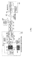
- Fig.1 illustrates a DSP-enabled coherent optical communication system according to one embodiment.
- Fig. 1 illustrates a DSP-enabled coherent optical communication system where a transmitter laser 102 with carrier frequency w s and phase noise ⁇ s(t) is modulated by an optical modulator 104.
- the modulated optical signal is then transmitted through an optical-amplified transmission link 106 to coherent mixer 110 where the optical signal is coherently mixed with a continuous wave (CW) light emitted from a local oscillator (LO) 108 with carrier frequency w L and phase noise denoted as ⁇ L(t).
- CW continuous wave
- LO local oscillator
- the in-phase and quadrature components at two orthogonal polarizations (nominally denoted as X-pol and Y-pol) of the received signal are converted, using an optical-to-electrical converter 112, into analog electrical signals, which are then digitized by analog-to-digital converter 114.
- the digitized signals 116 are then sent to a DSP unit 118 for signal recovery and demodulation.
- the process of signal recovery and demodulation using DSP unit 118 consists of five steps.
- the received digitized signal 116 at each polarization is sent to a long-memory 'static' linear filter/equalizer 120 for fiber chromatic dispersion (CD) compensation.
- CD fiber chromatic dispersion
- the received digitized signal 116 could be presented as a plurality of signals, each signal having its own polarization.
- the DSP receiver may include a plurality of the long-memory 'static' linear filter/equalizers 120, each of the long-memory 'static' linear filter/equalizers 120 configured to receive and process the signal having its own polarization.
- the received digitized signal 116 could be presented as a single signal having separate channels for each polarization (not shown).
- a DSP receiver may include a long-memory 'static' linear filter/equalizer 120 may be a single long-memory 'static' linear filter/equalizer 120 configured to receive and process a single signal having separate channels for each polarization. It is to be understood that in the case of the single signal, channels occupy different frequency bands.
- the CD-compensated signals 122 then pass through a butterfly-configured 2x2 adaptive equalizer 124 for polarization recovery and residual dispersion compensation. It is to be understood that the CD-compensated signals 122 may be presented as either a plurality of signals, as shown in Fig. 1 , or as a single signal having a plurality of channels (not shown). Because the rate of polarization change is much slower than the symbol rate (4 to 6 orders of magnitude slower), the required adaptive rate can be relatively slow, allowing the use of decision-directed adaptive equalization algorithms even with the use of high degree of time-interleave based parallel processing. Carrier frequency and phase recovery are performed following the polarization recovery.
- the carrier frequency offset between the signal source and the LO i.e., ⁇ w in Fig. 1
- the carrier frequency offset between the signal source and the LO i.e., ⁇ w in Fig. 1
- the total phase noise is estimated by using one of several algorithms, such as described in the " Nonlinear estimation of PSK-modulated carrier phase with application to burst digital transmission," A . J. Viterbi and A. M. Viterbi, IEEE Trans. Inf. Theory, vol. IT-29, no. 4, Jul. 1983 , " An improved feed-forward carrier recovery algorithm for coherent receiver with M-QAM modulation format," X. Zhou, IEEE Photonics Technol.
- the DSP functions described above work well for a liner transmission system using extremely narrow line-width lasers.
- a fiber transmission system using a narrow line width laser operating in the range from 100 kHz to 1 MHz there exist two major problems.
- the fiber system is not a linear system, and the Kerr nonlinear effect will cause additional signal distortion which is not compensated for or mitigated by using the conventional coherent receiver design as shown in Fig. 1 .
- the long-memory filter used in the receiver for the CD compensation will not only enhance the LO phase noise, but also convert the LO phase noise into amplitude noise.
- the long-memory CD-compensating filter will not enhance the phase noise from the signal source because the signal source passes through both the transmission fiber and the CD-compensating filter.
- the fiber dispersion and the CD-compensating filter will cancel out the impact from each other.
- the LO only passes through the CD-compensating filter so the impact from this filter cannot be canceled out.
- Such additional signal distortion caused by the interaction between the equalizer and the LO phase noise cannot be compensated for or mitigated by using the conventional one-tap phase-rotation filter as is shown in Fig. 1 .
- the signal distortion caused by both EPNI and FNE are correlated over multiple symbol periods.
- the symbol period is the time-domain duration for each data pulse.
- a time-varying multi-tap linear filtering process can be used to model both EPNI and FNE (to the first order).
- a fast-adaptive multi-tap digital filter replaces the conventional one-tap phase rotation filter. Such a fast-adaptive multi-tap filter performs not only the normal phase recovery function, but also helps reduce the penalty due to additional signal distortion caused by EPNI and FNE.
- Fig. 2 illustrates a DSP-enabled coherent optical communication system for optical impairment mitigation using the fast-adaptive multi-tap digital filter according to one embodiment.
- Transmitter laser 202 with carrier frequency w s and phase noise ⁇ s(t) is modulated by an optical modulator 204 of a transmitter 201.
- the modulated optical signal is then transmitted through an optically-amplified transmission link 206 to coherent mixer 210 where the modulated optical signal is then coherently mixed with a CW light emitted from a local oscillator (LO) 208 with carrier frequency w L and phase noise denoted as ⁇ L(t).
- LO local oscillator
- the in-phase and quadrature components at two orthogonal polarizations (nominally denoted as X-pol and Y-pol) of the received signal are converted into analog electrical signals using an optical-to-electrical converter 212.
- the electrical signals are then digitized using analog-to-digital converter 214.
- the digitized signals 316 are sent to a DSP unit 218 for signal recovery and demodulation.
- the received digitized signal 216 at each polarization is sent to a long-memory 'static' linear filter/equalizer 220 for fiber chromatic dispersion (CD) compensation.
- the CD-compensated signals 222 are then passed through a butterfly-configured 2x2 adaptive equalizer 224 for polarization recovery and residual dispersion compensation.
- the rate of polarization change ( ⁇ 1 MHz) is much slower than the symbol rate (10-100GHz, 4 to 6 orders of magnitude slower)
- the required adaptive rate can be relatively slow, allowing the use of decision-directed adaptive equalization algorithms even with the use of high degree of time-interleave based parallel processing.
- Carrier frequency and phase recovery are performed following the polarization recovery.
- the carrier frequency offset between the signal source and the LO (i.e., ⁇ w) is estimated using a frequency offset estimator 226 and then removed from the signal outputted from the butterfly-configured 2x2 adaptive equalizer 224 using a one-tap phase-rotation filter 228.
- the total phase noise is estimated by using a fast-adaptive multi-tap digital filter 232. Because laser phase noise typically varies 2 to 4 orders of magnitude faster than the state of polarization change (tens of microseconds versus tens of nanoseconds), the adaption rate for the fast-adaptive multi-tap digital filter 232 should be much faster than the regular polarization equalizer.
- a high adaptation rate can be realized using feed-forward based adaptation algorithms, such as, a block-by-block least square (LS) based algorithm, where the received data stream is divided into consecutive blocks, and filter coefficients of the said multi-tap filter are assumed to be constant over each data block, which may consist of tens to hundreds of consecutive data symbols.
- the changes of the filter coefficients from one block to the following block are estimated using LS based algorithms.
- multiple iterations may be applied to each data block for filter coefficients update.
- the phase-recovered signal 234 is then sent to the decision-making unit 236 for final signal demodulation.
- Fig. 3 illustrates a method for an optical impairment mitigation using a fast-adaptive multi-tap filter in the DSP-enabled coherent optical communication system as shown in Fig. 2 .
- a first compensated digitized signal is generated using a linear filter.
- the first compensated digitized signal is generated by sending a received digitized signal at each polarization to a long-memory 'static' linear filter/equalizer for fiber chromatic dispersion (CD) compensation.
- the received digitized signal is signal 216 of Fig. 2 and the long-memory 'static' linear filter/equalizer for fiber chromatic dispersion (CD) compensation is one or more 1 x1 CD equalizers 220 of Fig. 2 .
- a second compensated signal is generated by conducting a polarization recovery and residual dispersion compensation using an adaptive equalizer.
- the polarization recovery and residual dispersion compensation is performed by passing the first compensated digitized signal through a butterfly-configured 2x2 adaptive equalizer.
- step 304 is presented in Fig. 2 as signal 222 being transmitted to butterfly-configured 2x2 adaptive equalizer 224 for polarization recovery and residual dispersion compensation where the signal output from the butterfly-configured 2x2 adaptive equalizer 224 is the second compensated signal of step 304.
- the adaptation algorithm processor 238 of Fig. 2 runs the decision-directed adaptive equalization algorithm for the polarization recovery and residual dispersion compensation.
- a frequency offset of the second compensated signal is estimated.
- step 306 is performed as part of a carrier frequency recovery performed following the polarization recovery.
- the carrier frequency offset ⁇ w between the signal source and the LO is estimated using frequency offset estimator 226 of Fig. 2 .
- the frequency-recovered signal is generated by removing the frequency offset of the second compensated signal.
- the carrier frequency offset ⁇ w is removed by one or more single-tap filters 228 of Fig. 2 .
- the removal of the carrier frequency offset ⁇ w in step 308 results in generation of frequency-recovered signal 240 of Fig. 2 .
- a phase-recovered signal is generated by performing a phase recovery of the frequency-recovered signal using a fast-adaptive multi-tap digital filter.
- the adaption rate for the proposed fast-adaptive multi-tap digital filter should be much faster than the regular polarization equalizer because laser phase noise typically varies 2 to 4 orders of magnitude faster than the state of polarization change (tens of microseconds versus tens of nanoseconds).
- a fast adaptation rate is achieved by using feed-forward based adaptation algorithms run on fast adaptive algorithm processor 230 of Fig. 2 .
- a classic block-by-block least square (LS) based algorithm is used as the feed-forward based adaptation algorithm.
- the method for an optical impairment mitigation of Fig. 3 concludes with step 312 where the phase-recovered signal generated at step 310 is demodulated.
- Fig. 4 illustrates an exemplary block-by-block based feed-forward adaption solution for fast adaption of the fast-adaptive multi-tap digital filter 232 of Fig. 2 .
- the frequency-recovered signal generated at step 308 of Fig. 3 , is divided into blocks having multiple overlap symbols introduced between the blocks.
- a carrier phase over each block is estimated using common phase estimation algorithms, where the phase noise is assumed to be a constant over a multiple symbol period and it is also assumed that there is negligible phase noise to amplitude noise conversion.
- an estimated carrier phase is removed using the fast-adaptive multi-tap digital filter 232 of Fig. 2 .
- an initial decision is made.
- the decision means the process in which a receiver determines the value of transmitted symbols in a signal. For example, if the transmitter sends "10101 to the receiver by pulse amplitude modulation, due to the noise corruption, the receiver needs to make a decision as to which pulse symbol has a value of "1" and which pulse symbol has a value of "0.”
- the initial decision is made based on performing strictly phase recovery over a current data block.
- the initial decision may also be made by applying the recovered phase of a prior data block to the current data block or by directly applying the EPNI/FNE filter coefficients acquired from the prior data block to the current data block, where the starting phase or EPNI/FNE coefficients may be obtained using a starting training sequence. Since the block length cannot be too large due to the need for rapid adaption, accumulated amplifier noise may degrade the performance of the fast-adaptive multi-tap digital filter. This drawback may be alleviated by joint optimization of the fast-adaptive multi-tap digital filter at both polarizations because the phase noise in X- and Y-polarization is usually correlated (since they are typically from the same source).
- one or more 'optimal' coefficients of the fast-adaptive multi-tap digital filter are estimated by using for example well-known LS based algorithms.
- 'optimal' coefficients of the fast-adaptive multi-tap digital filter are updated with the one or more optimal coefficients estimated at step 410.
- the frequency-recovered signal of step 308 of Fig. 3 is equalized using the fast-adaptive multi-tap digital filter having updated 'optimal' coefficients.
- a decision is made by the decision-making unit 236 with respect to the frequency-recovered signal equalized at step 414. It is to be understood that, to reduce the impact of imperfect decision accuracy, multiple iterations may be applied to each data block for filter coefficients update.
- the method of Fig. 3 may also be used for the case where the long-memory CD-compensation filter is placed at the transmitter (i. e. pre-compensation).
- the long-memory CD-compensation filter is placed at the transmitter, there is no long memory filter placed at the receiver, so the LO will not be affected by the impact of long-memory filter.
- the transmitter source will experience only the fiber dispersion and the impact from fiber dispersion cannot be canceled out. Accordingly, in this case, the interaction between the fiber dispersion and the signal source phase noise will be similar to the interaction between the LO and the CD-compensating filter and therefore can also be mitigated by using the proposed method.
- Fig. 3 can be easily extended to future space division multiplexing (SDM) systems, where not only a long-memory filter is required for fiber CD compensation, but a multi-input multi-output (MIMO) equalizer having a substantial length may also be needed (e.g. the use of few-mode or coupled multi-core fibers) for modal dispersion compensation.
- MIMO multi-input multi-output
- the impairment caused by the interaction between the long MIMO equalizer and the laser phase noise as well as the impairments caused by inter-mode nonlinear effects may be compensated by the proposed fast-adaptive multi-tap equalization method.
- the use of multiple spatial modes can be used to enable the improvement of the EPNI/FNE equalization performance by joint optimizing the equalizer coefficients over multiple spatial modes.
- the impairment mitigation method described above has been numerically verified for a 7-channel 50GHz-spaced 49Gbaud PDM-16QAM system (operating at 392-Gb/s per channel bit rate, with Nyquist pulse shaping using a roll off factor 0.01) by using a block-by-block iterative LS algorithm.
- the transmission link consists of total 20 erbium-doped-fiber-amplified (EDFA) spans, and each span is composed of 100km of large area fiber (dispersion coefficient and fiber loss are assumed to be 21 ps/nm/km and 0.18dB/km, respectively) and EDFA-only amplification (noise figure is assumed to be 5dB).
- No inline optical dispersion compensation is used for this simulation.
- polarization-mode dispersion (PMD) and polarization-dependent loss is not considered in this simulation.
- PMD polarization-mode dispersion
- PMD polarization-dependent loss
- Fig. 5 illustrates an exemplary Bit-Error-Rate performance of a Wavelength-Division Demultiplexing system with and without using of the fast-adaptive multi-tap digital filter.
- Fig. 5 shows the bit error ratio (BER) performance of the middle channel (ch.4) versus the laser line width at the optimal signal launch power 3dBm/channel.
- BER bit error ratio
- Line 502 depicts the results generated using a conventional coherent receiver with a sliding-window based two-stage maximum likelihood phase recovery algorithm
- line 504 depicts the result generated by the proposed EPNI/FNE mitigation method using the fast-adaptive multi-tap digital filter, where a 5-tap Ts-spaced (where Ts denotes the symbol period) 1 x1 linear equalizer operating with a block-by-block adaptive LS algorithm is used at each polarization for simultaneous phase recovery and additional EPNI/FNE distortion mitigation.
- the block length is chosen to be 80 symbols (including 5 overlap symbols) and three iterations are applied for each data block, where the initial decision for each data block is made based on the same phase recovery algorithm used for the conventional coherent receiver (i.e. for the blue symbols).
- the proposed method effectively mitigates the impairments caused by EPNI and FNE.
- the proposed method improves the Q performance by 0.25dB by mitigating the impairments caused by FNE.
- the proposed method improves the Q performance by 1.15dB by mitigating the impairments from both EPNI and FNE.
- a 1.1dB Q performance improvement can translate into a transmission reach increase by approximately 30%.
- the performance improvement of the proposed method can also be clearly seen from the constellation diagrams shown in Fig.
- constellation diagram 601 illustrates the results generated using a conventional coherent receiver with a sliding-window based two-stage maximum likelihood phase recovery algorithm and where constellation diagram 602 illustrates the results generated by the proposed new EPNI/FNE mitigation method using the fast-adaptive multi-tap digital filter.
- the proposed fast-adaptive multi-tap digital filter can be implemented as a 1 x1 linear filter for each polarization, or each spatial mode for an SDM system, where the filter coefficients may be optimized either independently for each polarization/spatial mode or optimized by jointly considering more than one polarizations/spatial modes.
- the proposed fast-adaptive multi-tap digital filter may also be implemented as a butterfly-configured NxN MIMO equalizer for joint optimization of multiple spatial modes (two orthogonal polarizations can be assumed as two spatial modes).
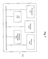
- FIG. 7 illustrates a high-level block diagram of an exemplary computer that may be used for implementing a new DSP-enabled coherent optical communication system and a method for optical impairment mitigation using the fast-adaptive multi-tap digital filter.
- Computer 700 comprises a processor 701 operatively coupled to a data storage device 702 and a memory 703.
- Processor 701 controls the overall operation of computer 700 by executing computer program instructions that define such operations.
- the computer program instructions may be stored in data storage device 702, or other computer readable medium, and loaded into memory 703 when execution of the computer program instructions is desired.
- FIGS. 4 and 5 can be defined by the computer program instructions stored in memory 703 and/or data storage device 702 and controlled by processor 701 executing the computer program instructions.
- Computer 700 can be implemented as computer executable code programmed by one skilled in the art to perform an algorithm defined by the method steps of FIGS. 4 and 5 . Accordingly, by executing the computer program instructions, the processor 701 executes an algorithm defined by the method steps of FIGS. 4 and 5 .
- Computer 700 also includes one or more network interfaces 705 for communicating with other devices via a network.
- Computer 700 also includes one or more input/output devices 704 that enable user interaction with computer 700 (e.g., display, keyboard, mouse, speakers, buttons, etc.).
- Processor 701 may include both general and special purpose microprocessors, and may be the sole processor or one of multiple processors of computer 700.
- Processor 701 may comprise one or more central processing units (CPUs), for example.
- processor 701, data storage device 702, and/or memory 703 may include, be supplemented by, or incorporated in, one or more application-specific integrated circuits (ASICs) and/or one or more field programmable gate arrays (FPGAs).
- ASICs application-specific integrated circuits
- FPGAs field programmable gate arrays
- Data storage device 702 and memory 703 each comprise a tangible non-transitory computer readable storage medium.
- Data storage device 702, and memory 703, may each include high-speed random access memory, such as dynamic random access memory (DRAM), static random access memory (SRAM), double data rate synchronous dynamic random access memory (DDR RAM), or other random access solid state memory devices, and may include non-volatile memory, such as one or more magnetic disk storage devices such as internal hard disks and removable disks, magnetooptical disk storage devices, optical disk storage devices, flash memory devices, semiconductor memory devices, such as erasable programmable read-only memory (EPROM), electrically erasable programmable read-only memory (EEPROM), compact disc read-only memory (CD-ROM), digital versatile disc read-only memory (DVD-ROM) disks, or other non-volatile solid state storage devices.
- DRAM dynamic random access memory
- SRAM static random access memory
- DDR RAM double data rate synchronous dynamic random access memory
- non-volatile memory such as one or more
- Input/output devices 705 may include peripherals, such as a printer, scanner, display screen, etc.
- input/output devices 704 may include a display device such as a cathode ray tube (CRT), plasma or liquid crystal display (LCD) monitor for displaying information to the user, a keyboard, and a pointing device such as a mouse or a trackball by which the user can provide input to computer 700.
- display device such as a cathode ray tube (CRT), plasma or liquid crystal display (LCD) monitor for displaying information to the user
- keyboard such as a keyboard
- pointing device such as a mouse or a trackball by which the user can provide input to computer 700.
- FIG. 7 is a high level representation of some of the components of such a computer for illustrative purposes.
Landscapes
- Engineering & Computer Science (AREA)
- Computer Networks & Wireless Communication (AREA)
- Signal Processing (AREA)
- Physics & Mathematics (AREA)
- Electromagnetism (AREA)
- Power Engineering (AREA)
- Optical Communication System (AREA)
- Cable Transmission Systems, Equalization Of Radio And Reduction Of Echo (AREA)
- Light Guides In General And Applications Therefor (AREA)
Abstract
Description
- The popularity of multimedia communications services over packet data networks, such as the Internet, continues to grow. Consequently, the demand for higher capacity in core data transport networks continues to grow. For service providers, core data transport networks are typically optical networks based on fiber optic technology. To meet the ever-growing capacity demand, 100G/s per channel data rate operating at 2bit/s/Hz spectral efficiency (SE) by using quadrature phase shift keying in the pulse-density (PDM-QPSK) modulation and digital signal processing (DSP) enabled coherent detection has been commercially deployed in the existing core networks. Also, research for the next generation of transport systems operating at even higher data rate (likely at 400Gb/s or above) and higher SE by using more spectrally efficient high-order modulation formats (such as the well known quadrature amplitude modulation (QAM)) is underway. However, recent experimental results have revealed that it is extremely challenging to achieve long-reach transmission using high-order modulation formats because they are more vulnerable to various transmission impairments such as fiber nonlinear effects, laser phase noise, and amplifier noise.
- To address the challenge caused by fiber nonlinear effects, several digital nonlinear compensation methods have been proposed, including the digital backward-propagation (DBP) based methods and a Volterra-based nonlinear equalization method. However, the implementation complexity of these digital methods is prohibitively high, making it almost impossible for them to be realized for any practical high-speed transmission systems. Several mid-link phase-conjugation based methods have also been proposed. However, these methods generally work well only for point-to-point submarine systems or specially designed super-channel systems. For typical terrestrial optical networks where reconfigurable optical add/drop multiplexers (ROADMs) are used to route optical wavelengths and different wavelength channels usually end up at different locations, there is still no feasible solution to mitigate fiber nonlinear effects for high-speed coherent optical transmission systems.
- To reduce the impact of laser phase noise on system performance, several single-tap phase rotation filter (with fast adaptive rate) based phase recovery methods have been proposed. However, these methods only work well for systems without using long-memory equalizer at the receiver, i.e. the short-reach system or long-reach system using inline optical dispersion compensation. Because the use of inline optical dispersion compensation not only increases the complexity of the inline optical amplifier design, but also significantly reduces fiber nonlinear tolerance, purely electrical/digital dispersion compensation is usually required in a high-speed coherent optical transmission system. For such a communication system, a linear digital filter/equalizer with very long memory length has to be introduced at the receiver to compensate for the accumulated dispersion from the transmission fiber.
- It has been determined that the use of long-memory filter/equalizer at the receiver (or at the transmitter for pre-compensation) will not only enhance the received phase noise, but will also convert the phase noise into amplitude noise, causing additional signal distortion which cannot be mitigated using the traditional carrier phase recovery method. Moreover, it has been determined that the penalty from such an equalizer-phase noise interaction increases with the data rate and can pose a problem for future 400-Gb/s systems operating at a very high baud rate. To address this problem, a hardware-based laser phase noise compensation method has recently been proposed. However, this method is very complex and costly because it requires an additional set of coherent receiver to measure the laser phase noise.
- The present disclosure is generally directed to a DSP-based solution to reduce transmission impairments such as fiber nonlinear effects, laser phase noise, and amplifier noise for long-reach transmission of signals using high-order modulation formats. In one embodiment, a method and system is directed to a single fast-adaptive multi-tap digital filter for simultaneous mitigation of optical impairment from both equalizer-phase noise interaction (EPNI) and fiber nonlinear effects (FNE). In another embodiment, the method and system is directed to the use of single fast-adaptive multi-tap digital filter to perform the common phase recovery function in addition to simultaneous mitigation of optical impairment from both EPNI and FNE.
-
-
Fig. 1 illustrates a DSP-enabled coherent optical communication system, according to one embodiment; -
Fig. 2 illustrates a system for optical impairment mitigation for high-speed optical communication systems, according to one embodiment; -
Fig. 3 illustrates a flow-chart showing a method for optical impairment mitigation for high-speed optical communication systems, according to one embodiment; -
Fig. 4 illustrates an exemplary flow-chart showing a block-by-block based feed-forward adaption solution for fast adaption of the fast-adaptive multi-tap digital filter, according to one embodiment; -
Fig. 5 illustrates an exemplary Bit-Error-Rate performance of a Wavelength-Division Demultiplexing system with and without using of the fast-adaptive multi-tap digital filter, according to one embodiment; -
Fig. 6 shows exemplary simulated constellation diagrams for the Wavelength-Division Demultiplexing system with and without the use of the fast-adaptive multi-tap digital filter; and -
Fig. 7 illustrates a high-level block diagram of an exemplary computer that may be used for implementing a DSP-enabled coherent optical communication system and a method for optical impairment mitigation using the fast-adaptive multi-tap digital filter. - The present disclosure is directed to a method and system for simultaneous mitigation of optical impairment from both equalizer-phase noise interaction (EPNI) and fiber nonlinear effects (FNE). In one embodiment, the method is directed to simultaneous mitigation of optical impairment from both equalizer-phase noise interaction (EPNI) and fiber nonlinear effects (FNE) using a fast-adaptive multi-tap digital filter.
-
Fig.1 illustrates a DSP-enabled coherent optical communication system according to one embodiment. Specifically,Fig. 1 illustrates a DSP-enabled coherent optical communication system where atransmitter laser 102 with carrier frequency ws and phase noise θs(t) is modulated by anoptical modulator 104. The modulated optical signal is then transmitted through an optical-amplifiedtransmission link 106 tocoherent mixer 110 where the optical signal is coherently mixed with a continuous wave (CW) light emitted from a local oscillator (LO) 108 with carrier frequency wL and phase noise denoted as θL(t). After mixing incoherent mixer 110, the in-phase and quadrature components at two orthogonal polarizations (nominally denoted as X-pol and Y-pol) of the received signal are converted, using an optical-to-electrical converter 112, into analog electrical signals, which are then digitized by analog-to-digital converter 114. Thedigitized signals 116 are then sent to aDSP unit 118 for signal recovery and demodulation. - The process of signal recovery and demodulation using
DSP unit 118 consists of five steps. First, the receiveddigitized signal 116 at each polarization is sent to a long-memory 'static' linear filter/equalizer 120 for fiber chromatic dispersion (CD) compensation. In one embodiment, as shown inFig. 1 , the receiveddigitized signal 116 could be presented as a plurality of signals, each signal having its own polarization. In the case of the plurality of signals, the DSP receiver may include a plurality of the long-memory 'static' linear filter/equalizers 120, each of the long-memory 'static' linear filter/equalizers 120 configured to receive and process the signal having its own polarization. In another embodiment, the receiveddigitized signal 116 could be presented as a single signal having separate channels for each polarization (not shown). In the case of the single signal, a DSP receiver may include a long-memory 'static' linear filter/equalizer 120 may be a single long-memory 'static' linear filter/equalizer 120 configured to receive and process a single signal having separate channels for each polarization. It is to be understood that in the case of the single signal, channels occupy different frequency bands. - The CD-compensated
signals 122 then pass through a butterfly-configured 2x2adaptive equalizer 124 for polarization recovery and residual dispersion compensation. It is to be understood that the CD-compensatedsignals 122 may be presented as either a plurality of signals, as shown inFig. 1 , or as a single signal having a plurality of channels (not shown). Because the rate of polarization change is much slower than the symbol rate (4 to 6 orders of magnitude slower), the required adaptive rate can be relatively slow, allowing the use of decision-directed adaptive equalization algorithms even with the use of high degree of time-interleave based parallel processing. Carrier frequency and phase recovery are performed following the polarization recovery. For carrier frequency recovery, the carrier frequency offset between the signal source and the LO, i.e., Δw inFig. 1 , is estimated using afrequency offset estimator 126 and then removed using a one-tap phase-rotation filter 128. For carrier phase recovery, the total phase noise (from the signal source and the LO) is estimated by using one of several algorithms, such as described in the "Nonlinear estimation of PSK-modulated carrier phase with application to burst digital transmission," A . J. Viterbi and A. M. Viterbi, IEEE Trans. Inf. Theory, vol. IT-29, no. 4, Jul. 1983, "An improved feed-forward carrier recovery algorithm for coherent receiver with M-QAM modulation format," X. Zhou, IEEE Photonics Technol. Lett., Vol. 22, No. 14, pp. 1051-1053, July 15, 2010, and "Phase-Noise-Tolerant Two-Stage Carrier Recovery Concept for Higher Order QAM Formats," T. Pfau and R. No'e, IEEE J. SELECTED TOPICS IN QUANTUM ELECTRONICS, VOL. 16, NO. 5, pp. 1210-1216, SEP./OCT. 2010, using a phase estimator 130 and then removed using another one-tapphase rotation filter 132. The phase-recoveredsignal 134 is then sent to the decision-making unit 136 for final signal demodulation. - The DSP functions described above work well for a liner transmission system using extremely narrow line-width lasers. For a practical fiber transmission system using a narrow line width laser operating in the range from 100 kHz to 1 MHz, however, there exist two major problems. First, the fiber system is not a linear system, and the Kerr nonlinear effect will cause additional signal distortion which is not compensated for or mitigated by using the conventional coherent receiver design as shown in
Fig. 1 . Secondly, the long-memory filter used in the receiver for the CD compensation will not only enhance the LO phase noise, but also convert the LO phase noise into amplitude noise. The long-memory CD-compensating filter will not enhance the phase noise from the signal source because the signal source passes through both the transmission fiber and the CD-compensating filter. For the case of perfect CD compensation, the fiber dispersion and the CD-compensating filter will cancel out the impact from each other. On the contrary, the LO only passes through the CD-compensating filter so the impact from this filter cannot be canceled out. Such additional signal distortion caused by the interaction between the equalizer and the LO phase noise cannot be compensated for or mitigated by using the conventional one-tap phase-rotation filter as is shown inFig. 1 . - The signal distortion caused by both EPNI and FNE are correlated over multiple symbol periods. The symbol period is the time-domain duration for each data pulse. A time-varying multi-tap linear filtering process can be used to model both EPNI and FNE (to the first order). In one embodiment, a fast-adaptive multi-tap digital filter replaces the conventional one-tap phase rotation filter. Such a fast-adaptive multi-tap filter performs not only the normal phase recovery function, but also helps reduce the penalty due to additional signal distortion caused by EPNI and FNE.
-
Fig. 2 illustrates a DSP-enabled coherent optical communication system for optical impairment mitigation using the fast-adaptive multi-tap digital filter according to one embodiment.Transmitter laser 202 with carrier frequency ws and phase noise θs(t) is modulated by anoptical modulator 204 of atransmitter 201. The modulated optical signal is then transmitted through an optically-amplifiedtransmission link 206 tocoherent mixer 210 where the modulated optical signal is then coherently mixed with a CW light emitted from a local oscillator (LO) 208 with carrier frequency wL and phase noise denoted as θL(t). After mixing incoherent mixer 210, the in-phase and quadrature components at two orthogonal polarizations (nominally denoted as X-pol and Y-pol) of the received signal are converted into analog electrical signals using an optical-to-electrical converter 212. The electrical signals are then digitized using analog-to-digital converter 214. The digitized signals 316 are sent to aDSP unit 218 for signal recovery and demodulation. - In the
DSP unit 218 the receiveddigitized signal 216 at each polarization is sent to a long-memory 'static' linear filter/equalizer 220 for fiber chromatic dispersion (CD) compensation. The CD-compensatedsignals 222 are then passed through a butterfly-configured 2x2adaptive equalizer 224 for polarization recovery and residual dispersion compensation. As noted above, because the rate of polarization change (<1 MHz) is much slower than the symbol rate (10-100GHz, 4 to 6 orders of magnitude slower), the required adaptive rate can be relatively slow, allowing the use of decision-directed adaptive equalization algorithms even with the use of high degree of time-interleave based parallel processing. Carrier frequency and phase recovery are performed following the polarization recovery. For carrier frequency recovery, the carrier frequency offset between the signal source and the LO, (i.e., Δw) is estimated using a frequency offsetestimator 226 and then removed from the signal outputted from the butterfly-configured 2x2adaptive equalizer 224 using a one-tap phase-rotation filter 228. The total phase noise is estimated by using a fast-adaptive multi-tapdigital filter 232. Because laser phase noise typically varies 2 to 4 orders of magnitude faster than the state of polarization change (tens of microseconds versus tens of nanoseconds), the adaption rate for the fast-adaptive multi-tapdigital filter 232 should be much faster than the regular polarization equalizer. A high adaptation rate can be realized using feed-forward based adaptation algorithms, such as, a block-by-block least square (LS) based algorithm, where the received data stream is divided into consecutive blocks, and filter coefficients of the said multi-tap filter are assumed to be constant over each data block, which may consist of tens to hundreds of consecutive data symbols. The changes of the filter coefficients from one block to the following block are estimated using LS based algorithms. To reduce the impact of imperfect decision accuracy, multiple iterations may be applied to each data block for filter coefficients update. The phase-recoveredsignal 234 is then sent to the decision-making unit 236 for final signal demodulation. -
Fig. 3 illustrates a method for an optical impairment mitigation using a fast-adaptive multi-tap filter in the DSP-enabled coherent optical communication system as shown inFig. 2 . At step 302, a first compensated digitized signal is generated using a linear filter. Specifically, the first compensated digitized signal is generated by sending a received digitized signal at each polarization to a long-memory 'static' linear filter/equalizer for fiber chromatic dispersion (CD) compensation. In one embodiment, the received digitized signal is signal 216 ofFig. 2 and the long-memory 'static' linear filter/equalizer for fiber chromatic dispersion (CD) compensation is one or more 1x1 CD equalizers 220 ofFig. 2 . - At step 304, a second compensated signal is generated by conducting a polarization recovery and residual dispersion compensation using an adaptive equalizer. In one embodiment, the polarization recovery and residual dispersion compensation is performed by passing the first compensated digitized signal through a butterfly-configured 2x2 adaptive equalizer. In one embodiment, step 304 is presented in
Fig. 2 assignal 222 being transmitted to butterfly-configured 2x2adaptive equalizer 224 for polarization recovery and residual dispersion compensation where the signal output from the butterfly-configured 2x2adaptive equalizer 224 is the second compensated signal of step 304. It should be noted that because the rate of polarization change is much slower than the symbol rate (4 to 6 orders of magnitude slower), the required adaptive rate can be relatively slow, allowing the use of decision-directed adaptive equalization algorithms even with the use of high degree of time-interleave based parallel processing. In one embodiment, theadaptation algorithm processor 238 ofFig. 2 runs the decision-directed adaptive equalization algorithm for the polarization recovery and residual dispersion compensation. Atstep 306, a frequency offset of the second compensated signal is estimated. In one embodiment,step 306 is performed as part of a carrier frequency recovery performed following the polarization recovery. In one embodiment, for the carrier frequency recovery, the carrier frequency offset Δw between the signal source and the LO is estimated using frequency offsetestimator 226 ofFig. 2 . - At
step 308, the frequency-recovered signal is generated by removing the frequency offset of the second compensated signal. In one embodiment, the carrier frequency offset Δw is removed by one or more single-tap filters 228 ofFig. 2 . In one embodiment, the removal of the carrier frequency offset Δw instep 308 results in generation of frequency-recovered signal 240 ofFig. 2 . - At
step 310, a phase-recovered signal is generated by performing a phase recovery of the frequency-recovered signal using a fast-adaptive multi-tap digital filter. As noted above, the adaption rate for the proposed fast-adaptive multi-tap digital filter should be much faster than the regular polarization equalizer because laser phase noise typically varies 2 to 4 orders of magnitude faster than the state of polarization change (tens of microseconds versus tens of nanoseconds). In one embodiment, a fast adaptation rate is achieved by using feed-forward based adaptation algorithms run on fast adaptive algorithm processor 230 ofFig. 2 . In one embodiment, a classic block-by-block least square (LS) based algorithm is used as the feed-forward based adaptation algorithm. - The method for an optical impairment mitigation of
Fig. 3 concludes withstep 312 where the phase-recovered signal generated atstep 310 is demodulated. -
Fig. 4 illustrates an exemplary block-by-block based feed-forward adaption solution for fast adaption of the fast-adaptive multi-tapdigital filter 232 ofFig. 2 . - At
step 402, the frequency-recovered signal, generated atstep 308 ofFig. 3 , is divided into blocks having multiple overlap symbols introduced between the blocks. Atstep 404, a carrier phase over each block is estimated using common phase estimation algorithms, where the phase noise is assumed to be a constant over a multiple symbol period and it is also assumed that there is negligible phase noise to amplitude noise conversion. At step 406, an estimated carrier phase is removed using the fast-adaptive multi-tapdigital filter 232 ofFig. 2 . - At
step 408, an initial decision is made. A person skilled in the art would understand that "the decision" means the process in which a receiver determines the value of transmitted symbols in a signal. For example, if the transmitter sends "10101 to the receiver by pulse amplitude modulation, due to the noise corruption, the receiver needs to make a decision as to which pulse symbol has a value of "1" and which pulse symbol has a value of "0." In one embodiment, the initial decision is made based on performing strictly phase recovery over a current data block. But the initial decision may also be made by applying the recovered phase of a prior data block to the current data block or by directly applying the EPNI/FNE filter coefficients acquired from the prior data block to the current data block, where the starting phase or EPNI/FNE coefficients may be obtained using a starting training sequence. Since the block length cannot be too large due to the need for rapid adaption, accumulated amplifier noise may degrade the performance of the fast-adaptive multi-tap digital filter. This drawback may be alleviated by joint optimization of the fast-adaptive multi-tap digital filter at both polarizations because the phase noise in X- and Y-polarization is usually correlated (since they are typically from the same source). - At
step 410, using a signal initially decided atstep 408 as a reference signal, one or more 'optimal' coefficients of the fast-adaptive multi-tap digital filter are estimated by using for example well-known LS based algorithms. - At
step 412, 'optimal' coefficients of the fast-adaptive multi-tap digital filter are updated with the one or more optimal coefficients estimated atstep 410. - At
step 414, the frequency-recovered signal ofstep 308 ofFig. 3 is equalized using the fast-adaptive multi-tap digital filter having updated 'optimal' coefficients. At step 416, a decision is made by the decision-making unit 236 with respect to the frequency-recovered signal equalized atstep 414. It is to be understood that, to reduce the impact of imperfect decision accuracy, multiple iterations may be applied to each data block for filter coefficients update. - It should be noted that the method of
Fig. 3 may also be used for the case where the long-memory CD-compensation filter is placed at the transmitter (i. e. pre-compensation). For the case where the long-memory CD-compensation filter is placed at the transmitter, there is no long memory filter placed at the receiver, so the LO will not be affected by the impact of long-memory filter. However, the transmitter source will experience only the fiber dispersion and the impact from fiber dispersion cannot be canceled out. Accordingly, in this case, the interaction between the fiber dispersion and the signal source phase noise will be similar to the interaction between the LO and the CD-compensating filter and therefore can also be mitigated by using the proposed method. - It should also be noted that the method of
Fig. 3 can be easily extended to future space division multiplexing (SDM) systems, where not only a long-memory filter is required for fiber CD compensation, but a multi-input multi-output (MIMO) equalizer having a substantial length may also be needed (e.g. the use of few-mode or coupled multi-core fibers) for modal dispersion compensation. In this case, the impairment caused by the interaction between the long MIMO equalizer and the laser phase noise as well as the impairments caused by inter-mode nonlinear effects may be compensated by the proposed fast-adaptive multi-tap equalization method. It should be noted that the use of multiple spatial modes can be used to enable the improvement of the EPNI/FNE equalization performance by joint optimizing the equalizer coefficients over multiple spatial modes. - The impairment mitigation method described above has been numerically verified for a 7-channel 50GHz-spaced 49Gbaud PDM-16QAM system (operating at 392-Gb/s per channel bit rate, with Nyquist pulse shaping using a roll off factor 0.01) by using a block-by-block iterative LS algorithm. The transmission link consists of total 20 erbium-doped-fiber-amplified (EDFA) spans, and each span is composed of 100km of large area fiber (dispersion coefficient and fiber loss are assumed to be 21 ps/nm/km and 0.18dB/km, respectively) and EDFA-only amplification (noise figure is assumed to be 5dB). No inline optical dispersion compensation is used for this simulation. For simplicity, polarization-mode dispersion (PMD) and polarization-dependent loss is not considered in this simulation. For the laser sources, we assume that the signal source and the LO have identical line width.
-
Fig. 5 illustrates an exemplary Bit-Error-Rate performance of a Wavelength-Division Demultiplexing system with and without using of the fast-adaptive multi-tap digital filter. In an exemplary embodiment,Fig. 5 shows the bit error ratio (BER) performance of the middle channel (ch.4) versus the laser line width at the optimal signal launch power 3dBm/channel. Line 502 depicts the results generated using a conventional coherent receiver with a sliding-window based two-stage maximum likelihood phase recovery algorithm, whileline 504 depicts the result generated by the proposed EPNI/FNE mitigation method using the fast-adaptive multi-tap digital filter, where a 5-tap Ts-spaced (where Ts denotes the symbol period) 1 x1 linear equalizer operating with a block-by-block adaptive LS algorithm is used at each polarization for simultaneous phase recovery and additional EPNI/FNE distortion mitigation. In one embodiment, the block length is chosen to be 80 symbols (including 5 overlap symbols) and three iterations are applied for each data block, where the initial decision for each data block is made based on the same phase recovery algorithm used for the conventional coherent receiver (i.e. for the blue symbols). - Based on the results illustrated on
Fig. 5 , a person skilled in the art will understand that the proposed method effectively mitigates the impairments caused by EPNI and FNE. For the case that there is no phase noise, i.e. the laser line width is zero, the proposed method improves the Q performance by 0.25dB by mitigating the impairments caused by FNE. For a laser line width 0.8MHz (a typical line width for the widely used DFB laser), the proposed method improves the Q performance by 1.15dB by mitigating the impairments from both EPNI and FNE. A 1.1dB Q performance improvement can translate into a transmission reach increase by approximately 30%. The performance improvement of the proposed method can also be clearly seen from the constellation diagrams shown inFig. 6 where constellation diagram 601 illustrates the results generated using a conventional coherent receiver with a sliding-window based two-stage maximum likelihood phase recovery algorithm and where constellation diagram 602 illustrates the results generated by the proposed new EPNI/FNE mitigation method using the fast-adaptive multi-tap digital filter. - It is to be understood that the proposed fast-adaptive multi-tap digital filter can be implemented as a 1 x1 linear filter for each polarization, or each spatial mode for an SDM system, where the filter coefficients may be optimized either independently for each polarization/spatial mode or optimized by jointly considering more than one polarizations/spatial modes. Furthermore, the proposed fast-adaptive multi-tap digital filter may also be implemented as a butterfly-configured NxN MIMO equalizer for joint optimization of multiple spatial modes (two orthogonal polarizations can be assumed as two spatial modes).
-
FIG. 7 illustrates a high-level block diagram of an exemplary computer that may be used for implementing a new DSP-enabled coherent optical communication system and a method for optical impairment mitigation using the fast-adaptive multi-tap digital filter.Computer 700 comprises aprocessor 701 operatively coupled to adata storage device 702 and amemory 703.Processor 701 controls the overall operation ofcomputer 700 by executing computer program instructions that define such operations. The computer program instructions may be stored indata storage device 702, or other computer readable medium, and loaded intomemory 703 when execution of the computer program instructions is desired. Thus, the steps ofFIGS. 4 and5 can be defined by the computer program instructions stored inmemory 703 and/ordata storage device 702 and controlled byprocessor 701 executing the computer program instructions. For example, the computer program instructions can be implemented as computer executable code programmed by one skilled in the art to perform an algorithm defined by the method steps ofFIGS. 4 and5 . Accordingly, by executing the computer program instructions, theprocessor 701 executes an algorithm defined by the method steps ofFIGS. 4 and5 .Computer 700 also includes one ormore network interfaces 705 for communicating with other devices via a network.Computer 700 also includes one or more input/output devices 704 that enable user interaction with computer 700 (e.g., display, keyboard, mouse, speakers, buttons, etc.). -
Processor 701 may include both general and special purpose microprocessors, and may be the sole processor or one of multiple processors ofcomputer 700.Processor 701 may comprise one or more central processing units (CPUs), for example.Processor 701,data storage device 702, and/ormemory 703 may include, be supplemented by, or incorporated in, one or more application-specific integrated circuits (ASICs) and/or one or more field programmable gate arrays (FPGAs). -
Data storage device 702 andmemory 703 each comprise a tangible non-transitory computer readable storage medium.Data storage device 702, andmemory 703, may each include high-speed random access memory, such as dynamic random access memory (DRAM), static random access memory (SRAM), double data rate synchronous dynamic random access memory (DDR RAM), or other random access solid state memory devices, and may include non-volatile memory, such as one or more magnetic disk storage devices such as internal hard disks and removable disks, magnetooptical disk storage devices, optical disk storage devices, flash memory devices, semiconductor memory devices, such as erasable programmable read-only memory (EPROM), electrically erasable programmable read-only memory (EEPROM), compact disc read-only memory (CD-ROM), digital versatile disc read-only memory (DVD-ROM) disks, or other non-volatile solid state storage devices. - Input/
output devices 705 may include peripherals, such as a printer, scanner, display screen, etc. For example, input/output devices 704 may include a display device such as a cathode ray tube (CRT), plasma or liquid crystal display (LCD) monitor for displaying information to the user, a keyboard, and a pointing device such as a mouse or a trackball by which the user can provide input tocomputer 700. - One skilled in the art will recognize that an implementation of an actual computer or computer system may have other structures and may contain other components as well, and that
FIG. 7 is a high level representation of some of the components of such a computer for illustrative purposes. - The foregoing Detailed Description is to be understood as being in every respect illustrative and exemplary, but not restrictive, and the scope of the invention disclosed herein is not to be determined from the Detailed Description, but rather from the claims as interpreted according to the full breadth permitted by the patent laws. It is to be understood that the embodiments shown and described herein are only illustrative of the principles of the present invention and that various modifications may be implemented by those skilled in the art without departing from the scope and spirit of the invention. Those skilled in the art could implement various other feature combinations without departing from the scope and spirit of the invention.
Claims (15)
- A method comprising:compensating a signal using a linear filter thereby generating a first compensated signal;conducting a polarization recovery and residual dispersion compensation of the first compensated signal using an adaptive equalizer having a first adaptation rate thereby generating a second compensated signal;estimating a frequency offset by conducting a carrier frequency recovery of the second compensated signal and removing the frequency offset using a one-tap filter thereby generating a frequency-recovered signal;performing a phase recovery of the frequency-recovered signal using a fast-adaptive multi-tap digital filter thereby generating a phase-recovered signal; anddemodulating the phase-recovered signal.
- The method of claim 1, wherein performing a phase recovery further comprises:dividing the frequency-recovered signal into a plurality of data blocks;estimating a carrier phase for each of the plurality of data blocks using a common phase estimation algorithm;removing the carrier phase estimated from each of the plurality of data blocks using the fast-adaptive multi-tap digital filter;identifying a first signal within each of the plurality of data blocks, wherein the first signal is the phase-recovered signal;estimating a plurality of coefficients of the fast-adaptive multi-tap digital filter by using the first signal as a reference signal;updating the plurality of coefficients of the fast-adaptive multi-tap digital filter;equalizing the frequency-recovered signal using the fast-adaptive multi-tap digital filter with the plurality of coefficients updated thereby generating an equalized signal; andidentifying the equalized signal.
- The method of claim 1 or claim 2, wherein the fast-adaptive multi-tap digital filter has a second adaptation rate that exceeds the first adaptation rate.
- The method of claim 3, wherein the second adaptation rate is generated by a feed-forward-based adaptation algorithm.
- The method of any preceding claim, wherein the signal comprises a digitized signal at a first orthogonal polarization and a digitized signal at a second orthogonal polarization.
- The method of any preceding claim, wherein the frequency offset is a signal frequency offset between a source of the signal and a local oscillator.
- The method of claim any preceding claim, wherein demodulating the phase-recovered signal comprises inputting the phase-recovered signal into a signal decision unit.
- An apparatus comprising:a processor; anda memory to store computer program instructions, the computer program instructions when executed on the processor, cause the processor to perform operations comprising:compensating a signal using a linear filter thereby generating a first compensated signal;conducting a polarization recovery and residual dispersion compensation of the first compensated signal using an adaptive equalizer having a first adaptation rate thereby generating a second compensated signal;estimating a frequency offset by conducting a carrier frequency recovery of the second compensated signal and removing the frequency offset using a one-tap filter thereby generating a frequency-recovered signal;performing a phase recovery of the frequency-recovered signal using a fast-adaptive multi-tap digital filter thereby generating a phase-recovered signal; anddemodulating the phase-recovered signal.
- The apparatus of claim 8, wherein performing a phase recovery further comprises:dividing the frequency-recovered signal into a plurality of data blocks;estimating a carrier phase for each of the plurality of data blocks using a common phase estimation algorithm;removing the carrier phase estimated from each of the plurality of data blocks using the fast-adaptive multi-tap digital filter;identifying a first signal within each of the plurality of data blocks, wherein the first signal is the phase-recovered signal;estimating a plurality of coefficients of the fast-adaptive multi-tap digital filter by using the first signal as a reference signal;updating the plurality of coefficients of the fast-adaptive multi-tap digital filter;equalizing the frequency-recovered signal using the fast-adaptive multi-tap digital filter with the plurality of coefficients updated thereby generating an equalized signal; andidentifying the equalized signal.
- The apparatus of claim 8 or claim 9, wherein the fast-adaptive multi-tap digital filter has a second adaptation rate that exceeds the first adaptation rate.
- The apparatus as claimed in claim10, wherein the second adaptation rate is generated by a feed-forward-based adaptation algorithm.
- The apparatus as claimed in any of claims 8 to 11, wherein the signal comprises a digitized signal at a first orthogonal polarization and a digitized signal at a second orthogonal polarization.
- The apparatus as claimed in any of claims 8 to 12, wherein the frequency offset is a signal frequency offset between a source of the signal and a local oscillator.
- The apparatus as claimed in any of claims 8 to 13, wherein demodulating the phase-recovered signal comprises inputting the phase-recovered signal into a signal decision unit.
- A computer readable medium storing computer program instructions which, when executed on a processor, cause the processor to implement a method as defined in any of claims 1 to 7.
Applications Claiming Priority (1)
| Application Number | Priority Date | Filing Date | Title |
|---|---|---|---|
| US14/017,433 US9191120B2 (en) | 2013-09-04 | 2013-09-04 | Method and system for optical impairments mitigation for high-speed optical communication systems |
Publications (3)
| Publication Number | Publication Date |
|---|---|
| EP2846505A2 true EP2846505A2 (en) | 2015-03-11 |
| EP2846505A3 EP2846505A3 (en) | 2015-04-01 |
| EP2846505B1 EP2846505B1 (en) | 2016-08-24 |
Family
ID=51494110
Family Applications (1)
| Application Number | Title | Priority Date | Filing Date |
|---|---|---|---|
| EP14183432.5A Not-in-force EP2846505B1 (en) | 2013-09-04 | 2014-09-03 | A method and system for optical impairment mitigation for high-speed optical communication systems |
Country Status (2)
| Country | Link |
|---|---|
| US (3) | US9191120B2 (en) |
| EP (1) | EP2846505B1 (en) |
Cited By (1)
| Publication number | Priority date | Publication date | Assignee | Title |
|---|---|---|---|---|
| US10404380B2 (en) | 2016-11-10 | 2019-09-03 | Fujitsu Limited | Compensation apparatus for offset drift, received signal recovery apparatus and receiver |
Families Citing this family (24)
| Publication number | Priority date | Publication date | Assignee | Title |
|---|---|---|---|---|
| US9531472B2 (en) * | 2013-05-06 | 2016-12-27 | Huawei Technologies Co., Ltd. | Coherent waveform conversion in optical networks |
| US9531624B2 (en) | 2013-08-05 | 2016-12-27 | Riverbed Technology, Inc. | Method and apparatus for path selection |
| US9191120B2 (en) * | 2013-09-04 | 2015-11-17 | At&T Intellectual Property I, L.P. | Method and system for optical impairments mitigation for high-speed optical communication systems |
| JP6281387B2 (en) * | 2014-04-07 | 2018-02-21 | 富士通株式会社 | Digital coherent receiver and receiving method |
| CN107409000B (en) * | 2015-04-10 | 2019-05-28 | 华为技术有限公司 | A coherent receiver, method and system for coherent light source frequency offset estimation and compensation |
| US9998235B2 (en) * | 2016-01-08 | 2018-06-12 | Google Llc | In-band optical interference mitigation for direct-detection optical communication systems |
| EP3220559A1 (en) * | 2016-03-14 | 2017-09-20 | Xieon Networks S.à r.l. | Processing parameter and resource sharing architecture for superchannel based transmission systems |
| WO2017214859A1 (en) * | 2016-06-14 | 2017-12-21 | 华为技术有限公司 | Uplink data balancing method, device, and system |
| EP3531586B1 (en) * | 2016-10-31 | 2022-01-26 | Huawei Technologies Co., Ltd. | Receiver and data reception method |
| KR20190127783A (en) * | 2017-03-21 | 2019-11-13 | 비프로스트 커뮤니케이션즈 에이피에스 | Optical communication system, apparatus and method including high performance optical receiver |
| CN107316649B (en) * | 2017-05-15 | 2020-11-20 | 百度在线网络技术(北京)有限公司 | Speech recognition method and device based on artificial intelligence |
| US10887022B2 (en) | 2017-06-15 | 2021-01-05 | Nokia Of America Corporation | Backward propagation with compensation of some nonlinear effects of polarization mode dispersion |
| WO2019023491A1 (en) * | 2017-07-27 | 2019-01-31 | The Regents Of The University Of Michigan | Line-of-sight optical communication for vehicle-to-vehicle (v2v) and vehicle-to-infrastructure (v2i) mobile communication networks |
| US10979148B1 (en) | 2019-11-06 | 2021-04-13 | Google Llc | Coherent receiver with mixed signal processing |
| CN112713942B (en) * | 2021-01-21 | 2021-10-22 | 电子科技大学 | A method for joint equalization of fiber signal damage based on MC-DBP algorithm |
| WO2022168218A1 (en) * | 2021-02-04 | 2022-08-11 | 日本電信電話株式会社 | Communication device and communication method |
| EP4099584B1 (en) | 2021-06-01 | 2024-04-03 | Nokia Solutions and Networks Oy | Mitigation of equalization-enhanced phase noise in a coherent optical receiver |
| CN114070407B (en) * | 2021-11-15 | 2023-02-03 | 北京科技大学 | A method that can simultaneously realize optical fiber link damage compensation and abnormal loss monitoring |
| CN114389714B (en) * | 2021-12-29 | 2025-02-21 | 国网天津市电力公司 | A channel damage compensation method for strong lightning current based on Hodler function model |
| CN114665976A (en) * | 2022-01-07 | 2022-06-24 | 南京鼎芯光电科技有限公司 | Kramers-Kronig-based integrated self-coherent receiver signal processing method and system |
| CN115426038B (en) * | 2022-08-02 | 2024-11-01 | 北京科技大学 | Non-invasive method and device for monitoring and positioning frequency offset of optical band-pass filter |
| US12483336B2 (en) * | 2023-03-30 | 2025-11-25 | Ciena Corporation | Method and system for fine frequency finesse filtering |
| CN117749313B (en) * | 2023-12-27 | 2025-08-01 | 苏州大学 | Multi-fiber space division multiplexing optical signal transmission method and system |
| CN119814169B (en) * | 2025-01-17 | 2025-09-23 | 紫金山实验室 | Four-dimensional modulation signal recovery method, device, equipment, medium and product |
Family Cites Families (36)
| Publication number | Priority date | Publication date | Assignee | Title |
|---|---|---|---|---|
| CA2184184C (en) * | 1994-12-28 | 2000-05-30 | Kenichi Higuchi | Apparatus and method for establishing acquisition of spreading code in cdma transmission system |
| US5692010A (en) * | 1996-01-17 | 1997-11-25 | Zenith Electronics Corporation | Adaptive equalizer with impulse noise protection |
| US5909462A (en) * | 1996-12-31 | 1999-06-01 | Lucent Technologies Inc. | System and method for improved spread spectrum signal detection |
| US6072841A (en) * | 1997-07-01 | 2000-06-06 | Hughes Electronics Corporation | Block phase estimator for the coherent detection of non-differentially phase modulated data bursts on rician fading channels |
| DE19737482A1 (en) * | 1997-08-28 | 1999-03-04 | Alsthom Cge Alcatel | Process for optical transmission over an optical fiber network, and optical transmission network |
| US6181754B1 (en) * | 1998-06-12 | 2001-01-30 | Cadence Design Systems, Inc. | System and method for modeling mixed signal RF circuits in a digital signal environment |
| US7266310B1 (en) * | 2003-04-29 | 2007-09-04 | Nortel Networks Limited | Digital compensation for optical transmission system |
| KR100603202B1 (en) * | 2004-06-28 | 2006-07-24 | 삼성전자주식회사 | Step size automatic control method and control device of LMS equalizer |
| US8041233B2 (en) * | 2004-07-14 | 2011-10-18 | Fundación Tarpuy | Adaptive equalization in coherent fiber optic communication |
| US7623797B2 (en) * | 2004-07-14 | 2009-11-24 | Fundacion Tarpuy | Compensating impairments of optical channel using adaptive equalization |
| KR100577260B1 (en) * | 2004-07-29 | 2006-05-10 | 엘지전자 주식회사 | Channel Equalizer and Method |
| CA2582917A1 (en) * | 2004-09-30 | 2006-04-13 | Viasat, Inc. | Frame-based carrier frequency and phase recovery system and method |
| US7522841B2 (en) * | 2005-10-21 | 2009-04-21 | Nortel Networks Limited | Efficient data transmission and training of data processing functions |
| US7555227B2 (en) * | 2005-10-21 | 2009-06-30 | Nortel Networks Limited | Polarization compensation in a coherent optical receiver |
| US9014252B2 (en) * | 2006-09-15 | 2015-04-21 | Lsi Corporation | Band-pass high-order analog filter backed hybrid receiver equalization |
| US7852915B2 (en) * | 2007-03-21 | 2010-12-14 | Freescale Semiconductor, Inc. | Adaptive equalizer for communication channels |
| US20080273641A1 (en) * | 2007-05-04 | 2008-11-06 | Jingnong Yang | Ofdm-based device and method for performing synchronization |
| US7974336B2 (en) * | 2008-04-23 | 2011-07-05 | Mediatek Inc. | Equalization system and method thereof |
| US20090324224A1 (en) * | 2008-06-30 | 2009-12-31 | Chongjin Xie | System, method and apparatus to suppress inter-channel nonlinearities in WDM systems with coherent detection |
| US8260156B2 (en) * | 2008-10-28 | 2012-09-04 | Nec Laboratories America, Inc. | Adaptive crossing frequency domain equalization (FDE) in digital PolMux coherent systems |
| US20100122003A1 (en) * | 2008-11-10 | 2010-05-13 | Nec Laboratories America, Inc. | Ring-based high speed bus interface |
| JP5440686B2 (en) * | 2009-03-27 | 2014-03-12 | 富士通株式会社 | Apparatus and method for equalizing chromatic dispersion, and digital coherent optical receiver |
| WO2010135868A1 (en) * | 2009-05-27 | 2010-12-02 | Fujitsu Limited | Filter coefficient control apparatus and method |
| US8666251B2 (en) * | 2009-06-23 | 2014-03-04 | University College Cork—National University Of Ireland Cork | Electronic dispersion compensation system and method |
| US8655191B2 (en) * | 2009-06-29 | 2014-02-18 | Alcatel Lucent | Symbol timing recovery in polarization division multiplexed coherent optical transmission system |
| US8340534B2 (en) * | 2009-08-07 | 2012-12-25 | Futurewei Technologies, Inc. | Side band pilot tone for digital signal processing in polarization multiplexed coherent optical communication system |
| KR101152268B1 (en) * | 2010-09-03 | 2012-06-08 | 주식회사 이노와이어리스 | I/Q offset measuring apparatus of receiver of SC-FDMA system |
| US8532504B2 (en) * | 2010-10-28 | 2013-09-10 | Opnext Subsystems, Inc. | Coherent optical receiver with adaptive equalizer initialization system |
| US9166774B2 (en) * | 2010-12-21 | 2015-10-20 | Avago Technologies General Ip (Singapore) Pte. Ltd. | Decoupling bang-bang CDR and DFE |
| US8995834B2 (en) * | 2011-12-22 | 2015-03-31 | Alcatel Lucent | Blind equalization for polarization-switched QPSK optical communications |
| HK1202002A1 (en) | 2012-02-10 | 2015-09-11 | 中兴通讯(美国)公司 | System and method for coherent detection with digital signal procession |
| US9313075B2 (en) * | 2012-08-17 | 2016-04-12 | Intel Corporation | Methods and arrangements for channel updates in wireless networks |
| US9214973B1 (en) * | 2012-08-29 | 2015-12-15 | Marvell International Ltd. | Time varying notch filter |
| US9191120B2 (en) * | 2013-09-04 | 2015-11-17 | At&T Intellectual Property I, L.P. | Method and system for optical impairments mitigation for high-speed optical communication systems |
| EP2922221B1 (en) * | 2014-03-19 | 2018-08-29 | ZTE Corporation | Techniques for blind equalization of high-order quadrature amplitude modulation signals |
| CN105610517B (en) * | 2014-11-14 | 2018-05-08 | 中兴通讯股份有限公司 | The iteration post-equalization of coherent optical heterodyne communicatio |
-
2013
- 2013-09-04 US US14/017,433 patent/US9191120B2/en active Active
-
2014
- 2014-09-03 EP EP14183432.5A patent/EP2846505B1/en not_active Not-in-force
-
2015
- 2015-10-15 US US14/884,107 patent/US9876569B2/en active Active
-
2018
- 2018-01-02 US US15/860,261 patent/US10243655B2/en active Active
Non-Patent Citations (3)
| Title |
|---|
| A . J. VITERBI; A. M. VITERBI: "Nonlinear estimation of PSK-modulated carrier phase with application to burst digital transmission", IEEE TRANS. INF. THEORY, vol. IT-29, no. 4, July 1983 (1983-07-01), XP000760812, DOI: doi:10.1109/TIT.1983.1056713 |
| T. PFAU; R. NO'E: "Phase-Noise-Tolerant Two-Stage Carrier Recovery Concept for Higher Order QAM Formats", IEEE J. SELECTED TOPICS IN QUANTUM ELECTRONICS, vol. 16, no. 5, September 2010 (2010-09-01), pages 1210 - 1216, XP011337403, DOI: doi:10.1109/JSTQE.2009.2034472 |
| X. ZHOU: "An improved feed-forward carrier recovery algorithm for coherent receiver with M-QAM modulation format", IEEE PHOTONICS TECHNOL. LETT., vol. 22, no. 14, 15 July 2010 (2010-07-15), pages 1051 - 1053, XP011309065 |
Cited By (1)
| Publication number | Priority date | Publication date | Assignee | Title |
|---|---|---|---|---|
| US10404380B2 (en) | 2016-11-10 | 2019-09-03 | Fujitsu Limited | Compensation apparatus for offset drift, received signal recovery apparatus and receiver |
Also Published As
| Publication number | Publication date |
|---|---|
| EP2846505A3 (en) | 2015-04-01 |
| US20180183520A1 (en) | 2018-06-28 |
| US9876569B2 (en) | 2018-01-23 |
| US9191120B2 (en) | 2015-11-17 |
| US20150063818A1 (en) | 2015-03-05 |
| US20160036527A1 (en) | 2016-02-04 |
| US10243655B2 (en) | 2019-03-26 |
| EP2846505B1 (en) | 2016-08-24 |
Similar Documents
| Publication | Publication Date | Title |
|---|---|---|
| US10243655B2 (en) | Method and system for optical impairment mitigation for high-speed optical communication systems | |
| US8260156B2 (en) | Adaptive crossing frequency domain equalization (FDE) in digital PolMux coherent systems | |
| Liu et al. | Intrachannel nonlinearity compensation by inverse Volterra series transfer function | |
| CN104170283B (en) | Optical sender, photoreceiver, optical transmission system and the method increasing system signal noise ratio | |
| EP2922221B1 (en) | Techniques for blind equalization of high-order quadrature amplitude modulation signals | |
| Zhou et al. | Advanced DSP for 400 Gb/s and beyond optical networks | |
| US9621391B2 (en) | Methods and apparatuses to improve reception of direct detection optical signals | |
| WO2012108421A1 (en) | Digital signal processing device | |
| Chagnon et al. | Analysis and experimental demonstration of novel 8PolSK-QPSK modulation at 5 bits/symbol for passive mitigation of nonlinear impairments | |
| Wan et al. | 64-Gb/s SSB-PAM4 transmission over 120-km dispersion-uncompensated SSMF with blind nonlinear equalization, adaptive noise-whitening postfilter and MLSD | |
| JP6467362B2 (en) | Optical transmission system | |
| Tipsuwannakul et al. | Performance comparisons of DP-16QAM and duobinary-shaped DP-QPSK for optical systems with 4.1 Bit/s/Hz spectral efficiency | |
| Fickers et al. | Decision-feedback equalization of bandwidth-constrained N-WDM coherent optical communication systems | |
| Wu et al. | Fixed short-FFT-size chromatic dispersion compensation for long-haul high-speed coherent optical transmission | |
| Asif et al. | Multi-span digital non-linear compensation for dual-polarization quadrature phase shift keying long-haul communication systems | |
| Che et al. | Rejuvenating direct modulation and direct detection for modern optical communications | |
| Tao et al. | Volterra series based blind equalization for nonlinear distortions in short reach optical CAP system | |
| Chang et al. | A faster-than-Nyquist PDM-16QAM scheme enabled by Tomlinson-Harashima precoding | |
| US12483337B2 (en) | Communication system, receiver, compensation amount calculation apparatus, distortion compensation method, and non-transitory computer readable medium | |
| Zhang et al. | Advanced linear and nonlinear compensations for 16QAM SC-400G unrepeatered transmission system | |
| Sjödin et al. | Long-haul transmission of PM-2PPM-QPSK at 42.8 Gbit/s | |
| Mori et al. | Modal dispersion compensation by using digital coherent receiver with adaptive equalization in multi-mode fiber transmission | |
| Ranzini et al. | Impact of nonlinear effects and mitigation on coherent optical systems | |
| Rosa et al. | Nonlinear effects compensation in optical coherent PDM-QPSK systems | |
| Asif et al. | Low-complexity logarithmic step-size-based filtered digital backward propagation algorithm for compensating fiber transmission impairments |
Legal Events
| Date | Code | Title | Description |
|---|---|---|---|
| PUAL | Search report despatched |
Free format text: ORIGINAL CODE: 0009013 |
|
| 17P | Request for examination filed |
Effective date: 20140903 |
|
| AK | Designated contracting states |
Kind code of ref document: A2 Designated state(s): AL AT BE BG CH CY CZ DE DK EE ES FI FR GB GR HR HU IE IS IT LI LT LU LV MC MK MT NL NO PL PT RO RS SE SI SK SM TR |
|
| AX | Request for extension of the european patent |
Extension state: BA ME |
|
| PUAI | Public reference made under article 153(3) epc to a published international application that has entered the european phase |
Free format text: ORIGINAL CODE: 0009012 |
|
| AK | Designated contracting states |
Kind code of ref document: A3 Designated state(s): AL AT BE BG CH CY CZ DE DK EE ES FI FR GB GR HR HU IE IS IT LI LT LU LV MC MK MT NL NO PL PT RO RS SE SI SK SM TR |
|
| AX | Request for extension of the european patent |
Extension state: BA ME |
|
| RIC1 | Information provided on ipc code assigned before grant |
Ipc: H04L 25/03 20060101AFI20150224BHEP Ipc: H04B 10/61 20130101ALI20150224BHEP |
|
| R17P | Request for examination filed (corrected) |
Effective date: 20150930 |
|
| RBV | Designated contracting states (corrected) |
Designated state(s): AL AT BE BG CH CY CZ DE DK EE ES FI FR GB GR HR HU IE IS IT LI LT LU LV MC MK MT NL NO PL PT RO RS SE SI SK SM TR |
|
| GRAP | Despatch of communication of intention to grant a patent |
Free format text: ORIGINAL CODE: EPIDOSNIGR1 |
|
| INTG | Intention to grant announced |
Effective date: 20160126 |
|
| GRAJ | Information related to disapproval of communication of intention to grant by the applicant or resumption of examination proceedings by the epo deleted |
Free format text: ORIGINAL CODE: EPIDOSDIGR1 |
|
| GRAR | Information related to intention to grant a patent recorded |
Free format text: ORIGINAL CODE: EPIDOSNIGR71 |
|
| GRAS | Grant fee paid |
Free format text: ORIGINAL CODE: EPIDOSNIGR3 |
|
| INTG | Intention to grant announced |
Effective date: 20160610 |
|
| GRAA | (expected) grant |
Free format text: ORIGINAL CODE: 0009210 |
|
| AK | Designated contracting states |
Kind code of ref document: B1 Designated state(s): AL AT BE BG CH CY CZ DE DK EE ES FI FR GB GR HR HU IE IS IT LI LT LU LV MC MK MT NL NO PL PT RO RS SE SI SK SM TR |
|
| REG | Reference to a national code |
Ref country code: GB Ref legal event code: FG4D |
|
| REG | Reference to a national code |
Ref country code: CH Ref legal event code: EP Ref country code: FR Ref legal event code: PLFP Year of fee payment: 3 |
|
| REG | Reference to a national code |
Ref country code: AT Ref legal event code: REF Ref document number: 823946 Country of ref document: AT Kind code of ref document: T Effective date: 20160915 |
|
| REG | Reference to a national code |
Ref country code: IE Ref legal event code: FG4D |
|
| REG | Reference to a national code |
Ref country code: DE Ref legal event code: R096 Ref document number: 602014003223 Country of ref document: DE |
|
| REG | Reference to a national code |
Ref country code: LT Ref legal event code: MG4D |
|
| REG | Reference to a national code |
Ref country code: NL Ref legal event code: MP Effective date: 20160824 |
|
| REG | Reference to a national code |
Ref country code: AT Ref legal event code: MK05 Ref document number: 823946 Country of ref document: AT Kind code of ref document: T Effective date: 20160824 |
|
| PG25 | Lapsed in a contracting state [announced via postgrant information from national office to epo] |
Ref country code: FI Free format text: LAPSE BECAUSE OF FAILURE TO SUBMIT A TRANSLATION OF THE DESCRIPTION OR TO PAY THE FEE WITHIN THE PRESCRIBED TIME-LIMIT Effective date: 20160824 Ref country code: NO Free format text: LAPSE BECAUSE OF FAILURE TO SUBMIT A TRANSLATION OF THE DESCRIPTION OR TO PAY THE FEE WITHIN THE PRESCRIBED TIME-LIMIT Effective date: 20161124 Ref country code: NL Free format text: LAPSE BECAUSE OF FAILURE TO SUBMIT A TRANSLATION OF THE DESCRIPTION OR TO PAY THE FEE WITHIN THE PRESCRIBED TIME-LIMIT Effective date: 20160824 Ref country code: IT Free format text: LAPSE BECAUSE OF FAILURE TO SUBMIT A TRANSLATION OF THE DESCRIPTION OR TO PAY THE FEE WITHIN THE PRESCRIBED TIME-LIMIT Effective date: 20160824 Ref country code: LT Free format text: LAPSE BECAUSE OF FAILURE TO SUBMIT A TRANSLATION OF THE DESCRIPTION OR TO PAY THE FEE WITHIN THE PRESCRIBED TIME-LIMIT Effective date: 20160824 Ref country code: RS Free format text: LAPSE BECAUSE OF FAILURE TO SUBMIT A TRANSLATION OF THE DESCRIPTION OR TO PAY THE FEE WITHIN THE PRESCRIBED TIME-LIMIT Effective date: 20160824 Ref country code: HR Free format text: LAPSE BECAUSE OF FAILURE TO SUBMIT A TRANSLATION OF THE DESCRIPTION OR TO PAY THE FEE WITHIN THE PRESCRIBED TIME-LIMIT Effective date: 20160824 |
|
| PG25 | Lapsed in a contracting state [announced via postgrant information from national office to epo] |
Ref country code: PT Free format text: LAPSE BECAUSE OF FAILURE TO SUBMIT A TRANSLATION OF THE DESCRIPTION OR TO PAY THE FEE WITHIN THE PRESCRIBED TIME-LIMIT Effective date: 20161226 Ref country code: SE Free format text: LAPSE BECAUSE OF FAILURE TO SUBMIT A TRANSLATION OF THE DESCRIPTION OR TO PAY THE FEE WITHIN THE PRESCRIBED TIME-LIMIT Effective date: 20160824 Ref country code: LV Free format text: LAPSE BECAUSE OF FAILURE TO SUBMIT A TRANSLATION OF THE DESCRIPTION OR TO PAY THE FEE WITHIN THE PRESCRIBED TIME-LIMIT Effective date: 20160824 Ref country code: ES Free format text: LAPSE BECAUSE OF FAILURE TO SUBMIT A TRANSLATION OF THE DESCRIPTION OR TO PAY THE FEE WITHIN THE PRESCRIBED TIME-LIMIT Effective date: 20160824 Ref country code: GR Free format text: LAPSE BECAUSE OF FAILURE TO SUBMIT A TRANSLATION OF THE DESCRIPTION OR TO PAY THE FEE WITHIN THE PRESCRIBED TIME-LIMIT Effective date: 20161125 Ref country code: BE Free format text: LAPSE BECAUSE OF NON-PAYMENT OF DUE FEES Effective date: 20160930 Ref country code: AT Free format text: LAPSE BECAUSE OF FAILURE TO SUBMIT A TRANSLATION OF THE DESCRIPTION OR TO PAY THE FEE WITHIN THE PRESCRIBED TIME-LIMIT Effective date: 20160824 |
|
| PG25 | Lapsed in a contracting state [announced via postgrant information from national office to epo] |
Ref country code: RO Free format text: LAPSE BECAUSE OF FAILURE TO SUBMIT A TRANSLATION OF THE DESCRIPTION OR TO PAY THE FEE WITHIN THE PRESCRIBED TIME-LIMIT Effective date: 20160824 Ref country code: EE Free format text: LAPSE BECAUSE OF FAILURE TO SUBMIT A TRANSLATION OF THE DESCRIPTION OR TO PAY THE FEE WITHIN THE PRESCRIBED TIME-LIMIT Effective date: 20160824 |
|
| REG | Reference to a national code |
Ref country code: DE Ref legal event code: R097 Ref document number: 602014003223 Country of ref document: DE |
|
| PG25 | Lapsed in a contracting state [announced via postgrant information from national office to epo] |
Ref country code: PL Free format text: LAPSE BECAUSE OF FAILURE TO SUBMIT A TRANSLATION OF THE DESCRIPTION OR TO PAY THE FEE WITHIN THE PRESCRIBED TIME-LIMIT Effective date: 20160824 Ref country code: BG Free format text: LAPSE BECAUSE OF FAILURE TO SUBMIT A TRANSLATION OF THE DESCRIPTION OR TO PAY THE FEE WITHIN THE PRESCRIBED TIME-LIMIT Effective date: 20161124 Ref country code: CZ Free format text: LAPSE BECAUSE OF FAILURE TO SUBMIT A TRANSLATION OF THE DESCRIPTION OR TO PAY THE FEE WITHIN THE PRESCRIBED TIME-LIMIT Effective date: 20160824 Ref country code: DK Free format text: LAPSE BECAUSE OF FAILURE TO SUBMIT A TRANSLATION OF THE DESCRIPTION OR TO PAY THE FEE WITHIN THE PRESCRIBED TIME-LIMIT Effective date: 20160824 Ref country code: BE Free format text: LAPSE BECAUSE OF FAILURE TO SUBMIT A TRANSLATION OF THE DESCRIPTION OR TO PAY THE FEE WITHIN THE PRESCRIBED TIME-LIMIT Effective date: 20160824 Ref country code: SM Free format text: LAPSE BECAUSE OF FAILURE TO SUBMIT A TRANSLATION OF THE DESCRIPTION OR TO PAY THE FEE WITHIN THE PRESCRIBED TIME-LIMIT Effective date: 20160824 Ref country code: SK Free format text: LAPSE BECAUSE OF FAILURE TO SUBMIT A TRANSLATION OF THE DESCRIPTION OR TO PAY THE FEE WITHIN THE PRESCRIBED TIME-LIMIT Effective date: 20160824 |
|
| REG | Reference to a national code |
Ref country code: IE Ref legal event code: MM4A |
|
| PG25 | Lapsed in a contracting state [announced via postgrant information from national office to epo] |
Ref country code: MC Free format text: LAPSE BECAUSE OF FAILURE TO SUBMIT A TRANSLATION OF THE DESCRIPTION OR TO PAY THE FEE WITHIN THE PRESCRIBED TIME-LIMIT Effective date: 20160824 |
|
| PLBE | No opposition filed within time limit |
Free format text: ORIGINAL CODE: 0009261 |
|
| STAA | Information on the status of an ep patent application or granted ep patent |
Free format text: STATUS: NO OPPOSITION FILED WITHIN TIME LIMIT |
|
| PG25 | Lapsed in a contracting state [announced via postgrant information from national office to epo] |
Ref country code: IE Free format text: LAPSE BECAUSE OF NON-PAYMENT OF DUE FEES Effective date: 20160903 |
|
| 26N | No opposition filed |
Effective date: 20170526 |
|
| REG | Reference to a national code |
Ref country code: FR Ref legal event code: PLFP Year of fee payment: 4 |
|
| PG25 | Lapsed in a contracting state [announced via postgrant information from national office to epo] |
Ref country code: LU Free format text: LAPSE BECAUSE OF NON-PAYMENT OF DUE FEES Effective date: 20160903 Ref country code: SI Free format text: LAPSE BECAUSE OF FAILURE TO SUBMIT A TRANSLATION OF THE DESCRIPTION OR TO PAY THE FEE WITHIN THE PRESCRIBED TIME-LIMIT Effective date: 20160824 |
|
| REG | Reference to a national code |
Ref country code: CH Ref legal event code: PL |
|
| PG25 | Lapsed in a contracting state [announced via postgrant information from national office to epo] |
Ref country code: HU Free format text: LAPSE BECAUSE OF FAILURE TO SUBMIT A TRANSLATION OF THE DESCRIPTION OR TO PAY THE FEE WITHIN THE PRESCRIBED TIME-LIMIT; INVALID AB INITIO Effective date: 20140903 |
|
| PG25 | Lapsed in a contracting state [announced via postgrant information from national office to epo] |
Ref country code: MT Free format text: LAPSE BECAUSE OF NON-PAYMENT OF DUE FEES Effective date: 20160930 Ref country code: CY Free format text: LAPSE BECAUSE OF FAILURE TO SUBMIT A TRANSLATION OF THE DESCRIPTION OR TO PAY THE FEE WITHIN THE PRESCRIBED TIME-LIMIT Effective date: 20160824 Ref country code: MK Free format text: LAPSE BECAUSE OF FAILURE TO SUBMIT A TRANSLATION OF THE DESCRIPTION OR TO PAY THE FEE WITHIN THE PRESCRIBED TIME-LIMIT Effective date: 20160824 Ref country code: IS Free format text: LAPSE BECAUSE OF FAILURE TO SUBMIT A TRANSLATION OF THE DESCRIPTION OR TO PAY THE FEE WITHIN THE PRESCRIBED TIME-LIMIT Effective date: 20160824 |
|
| PG25 | Lapsed in a contracting state [announced via postgrant information from national office to epo] |
Ref country code: LI Free format text: LAPSE BECAUSE OF NON-PAYMENT OF DUE FEES Effective date: 20170930 Ref country code: CH Free format text: LAPSE BECAUSE OF NON-PAYMENT OF DUE FEES Effective date: 20170930 |
|
| REG | Reference to a national code |
Ref country code: FR Ref legal event code: PLFP Year of fee payment: 5 |
|
| PG25 | Lapsed in a contracting state [announced via postgrant information from national office to epo] |
Ref country code: AL Free format text: LAPSE BECAUSE OF FAILURE TO SUBMIT A TRANSLATION OF THE DESCRIPTION OR TO PAY THE FEE WITHIN THE PRESCRIBED TIME-LIMIT Effective date: 20160824 Ref country code: TR Free format text: LAPSE BECAUSE OF FAILURE TO SUBMIT A TRANSLATION OF THE DESCRIPTION OR TO PAY THE FEE WITHIN THE PRESCRIBED TIME-LIMIT Effective date: 20160824 |
|
| PGFP | Annual fee paid to national office [announced via postgrant information from national office to epo] |
Ref country code: GB Payment date: 20230810 Year of fee payment: 10 |
|
| PGFP | Annual fee paid to national office [announced via postgrant information from national office to epo] |
Ref country code: FR Payment date: 20230808 Year of fee payment: 10 Ref country code: DE Payment date: 20230808 Year of fee payment: 10 |
|
| REG | Reference to a national code |
Ref country code: DE Ref legal event code: R119 Ref document number: 602014003223 Country of ref document: DE |
|
| GBPC | Gb: european patent ceased through non-payment of renewal fee |
Effective date: 20240903 |
|
| PG25 | Lapsed in a contracting state [announced via postgrant information from national office to epo] |
Ref country code: DE Free format text: LAPSE BECAUSE OF NON-PAYMENT OF DUE FEES Effective date: 20250401 |
|
| PG25 | Lapsed in a contracting state [announced via postgrant information from national office to epo] |
Ref country code: GB Free format text: LAPSE BECAUSE OF NON-PAYMENT OF DUE FEES Effective date: 20240903 |
|
| PG25 | Lapsed in a contracting state [announced via postgrant information from national office to epo] |
Ref country code: FR Free format text: LAPSE BECAUSE OF NON-PAYMENT OF DUE FEES Effective date: 20240930 |