EP2846435A1 - Communication system, charge control apparatus, vehicle and feeding apparatus - Google Patents
Communication system, charge control apparatus, vehicle and feeding apparatus Download PDFInfo
- Publication number
- EP2846435A1 EP2846435A1 EP13773137.8A EP13773137A EP2846435A1 EP 2846435 A1 EP2846435 A1 EP 2846435A1 EP 13773137 A EP13773137 A EP 13773137A EP 2846435 A1 EP2846435 A1 EP 2846435A1
- Authority
- EP
- European Patent Office
- Prior art keywords
- line
- control
- communication
- charging
- reference potential
- Prior art date
- Legal status (The legal status is an assumption and is not a legal conclusion. Google has not performed a legal analysis and makes no representation as to the accuracy of the status listed.)
- Granted
Links
Images


Classifications
-
- B—PERFORMING OPERATIONS; TRANSPORTING
- B60—VEHICLES IN GENERAL
- B60L—PROPULSION OF ELECTRICALLY-PROPELLED VEHICLES; SUPPLYING ELECTRIC POWER FOR AUXILIARY EQUIPMENT OF ELECTRICALLY-PROPELLED VEHICLES; ELECTRODYNAMIC BRAKE SYSTEMS FOR VEHICLES IN GENERAL; MAGNETIC SUSPENSION OR LEVITATION FOR VEHICLES; MONITORING OPERATING VARIABLES OF ELECTRICALLY-PROPELLED VEHICLES; ELECTRIC SAFETY DEVICES FOR ELECTRICALLY-PROPELLED VEHICLES
- B60L53/00—Methods of charging batteries, specially adapted for electric vehicles; Charging stations or on-board charging equipment therefor; Exchange of energy storage elements in electric vehicles
- B60L53/10—Methods of charging batteries, specially adapted for electric vehicles; Charging stations or on-board charging equipment therefor; Exchange of energy storage elements in electric vehicles characterised by the energy transfer between the charging station and the vehicle
- B60L53/14—Conductive energy transfer
-
- B—PERFORMING OPERATIONS; TRANSPORTING
- B60—VEHICLES IN GENERAL
- B60L—PROPULSION OF ELECTRICALLY-PROPELLED VEHICLES; SUPPLYING ELECTRIC POWER FOR AUXILIARY EQUIPMENT OF ELECTRICALLY-PROPELLED VEHICLES; ELECTRODYNAMIC BRAKE SYSTEMS FOR VEHICLES IN GENERAL; MAGNETIC SUSPENSION OR LEVITATION FOR VEHICLES; MONITORING OPERATING VARIABLES OF ELECTRICALLY-PROPELLED VEHICLES; ELECTRIC SAFETY DEVICES FOR ELECTRICALLY-PROPELLED VEHICLES
- B60L53/00—Methods of charging batteries, specially adapted for electric vehicles; Charging stations or on-board charging equipment therefor; Exchange of energy storage elements in electric vehicles
- B60L53/30—Constructional details of charging stations
- B60L53/305—Communication interfaces
-
- B—PERFORMING OPERATIONS; TRANSPORTING
- B60—VEHICLES IN GENERAL
- B60L—PROPULSION OF ELECTRICALLY-PROPELLED VEHICLES; SUPPLYING ELECTRIC POWER FOR AUXILIARY EQUIPMENT OF ELECTRICALLY-PROPELLED VEHICLES; ELECTRODYNAMIC BRAKE SYSTEMS FOR VEHICLES IN GENERAL; MAGNETIC SUSPENSION OR LEVITATION FOR VEHICLES; MONITORING OPERATING VARIABLES OF ELECTRICALLY-PROPELLED VEHICLES; ELECTRIC SAFETY DEVICES FOR ELECTRICALLY-PROPELLED VEHICLES
- B60L53/00—Methods of charging batteries, specially adapted for electric vehicles; Charging stations or on-board charging equipment therefor; Exchange of energy storage elements in electric vehicles
- B60L53/60—Monitoring or controlling charging stations
-
- H—ELECTRICITY
- H01—ELECTRIC ELEMENTS
- H01M—PROCESSES OR MEANS, e.g. BATTERIES, FOR THE DIRECT CONVERSION OF CHEMICAL ENERGY INTO ELECTRICAL ENERGY
- H01M10/00—Secondary cells; Manufacture thereof
- H01M10/42—Methods or arrangements for servicing or maintenance of secondary cells or secondary half-cells
- H01M10/44—Methods for charging or discharging
-
- H—ELECTRICITY
- H02—GENERATION; CONVERSION OR DISTRIBUTION OF ELECTRIC POWER
- H02J—ELECTRIC POWER NETWORKS; CIRCUIT ARRANGEMENTS OR SYSTEMS FOR SUPPLYING OR DISTRIBUTING ELECTRIC POWER; SYSTEMS FOR STORING ELECTRIC ENERGY
- H02J50/00—Circuit arrangements or systems for wireless supply or distribution of electric power
- H02J50/10—Circuit arrangements or systems for wireless supply or distribution of electric power using inductive coupling
-
- H—ELECTRICITY
- H02—GENERATION; CONVERSION OR DISTRIBUTION OF ELECTRIC POWER
- H02J—ELECTRIC POWER NETWORKS; CIRCUIT ARRANGEMENTS OR SYSTEMS FOR SUPPLYING OR DISTRIBUTING ELECTRIC POWER; SYSTEMS FOR STORING ELECTRIC ENERGY
- H02J50/00—Circuit arrangements or systems for wireless supply or distribution of electric power
- H02J50/80—Circuit arrangements or systems for wireless supply or distribution of electric power involving the exchange of data, concerning supply or distribution of electric power, between transmitting devices and receiving devices
-
- H—ELECTRICITY
- H02—GENERATION; CONVERSION OR DISTRIBUTION OF ELECTRIC POWER
- H02J—ELECTRIC POWER NETWORKS; CIRCUIT ARRANGEMENTS OR SYSTEMS FOR SUPPLYING OR DISTRIBUTING ELECTRIC POWER; SYSTEMS FOR STORING ELECTRIC ENERGY
- H02J7/00—Circuit arrangements for charging or discharging batteries or for supplying loads from batteries
- H02J7/40—Circuit arrangements for charging or discharging batteries or for supplying loads from batteries characterised by the exchange of charge or discharge related data
- H02J7/42—Circuit arrangements for charging or discharging batteries or for supplying loads from batteries characterised by the exchange of charge or discharge related data with electronic devices having internal batteries, e.g. mobile phones
-
- H—ELECTRICITY
- H04—ELECTRIC COMMUNICATION TECHNIQUE
- H04B—TRANSMISSION
- H04B5/00—Near-field transmission systems, e.g. inductive or capacitive transmission systems
- H04B5/20—Near-field transmission systems, e.g. inductive or capacitive transmission systems characterised by the transmission technique; characterised by the transmission medium
- H04B5/24—Inductive coupling
-
- H—ELECTRICITY
- H04—ELECTRIC COMMUNICATION TECHNIQUE
- H04B—TRANSMISSION
- H04B5/00—Near-field transmission systems, e.g. inductive or capacitive transmission systems
- H04B5/70—Near-field transmission systems, e.g. inductive or capacitive transmission systems specially adapted for specific purposes
- H04B5/79—Near-field transmission systems, e.g. inductive or capacitive transmission systems specially adapted for specific purposes for data transfer in combination with power transfer
-
- B—PERFORMING OPERATIONS; TRANSPORTING
- B60—VEHICLES IN GENERAL
- B60L—PROPULSION OF ELECTRICALLY-PROPELLED VEHICLES; SUPPLYING ELECTRIC POWER FOR AUXILIARY EQUIPMENT OF ELECTRICALLY-PROPELLED VEHICLES; ELECTRODYNAMIC BRAKE SYSTEMS FOR VEHICLES IN GENERAL; MAGNETIC SUSPENSION OR LEVITATION FOR VEHICLES; MONITORING OPERATING VARIABLES OF ELECTRICALLY-PROPELLED VEHICLES; ELECTRIC SAFETY DEVICES FOR ELECTRICALLY-PROPELLED VEHICLES
- B60L2270/00—Problem solutions or means not otherwise provided for
- B60L2270/10—Emission reduction
- B60L2270/14—Emission reduction of noise
- B60L2270/147—Emission reduction of noise electro magnetic [EMI]
-
- H—ELECTRICITY
- H02—GENERATION; CONVERSION OR DISTRIBUTION OF ELECTRIC POWER
- H02J—ELECTRIC POWER NETWORKS; CIRCUIT ARRANGEMENTS OR SYSTEMS FOR SUPPLYING OR DISTRIBUTING ELECTRIC POWER; SYSTEMS FOR STORING ELECTRIC ENERGY
- H02J2105/00—Networks for supplying or distributing electric power characterised by their spatial reach or by the load
- H02J2105/30—Networks for supplying or distributing electric power characterised by their spatial reach or by the load the load networks being external to vehicles, i.e. exchanging power with vehicles
- H02J2105/33—Networks for supplying or distributing electric power characterised by their spatial reach or by the load the load networks being external to vehicles, i.e. exchanging power with vehicles exchanging power with road vehicles
- H02J2105/37—Networks for supplying or distributing electric power characterised by their spatial reach or by the load the load networks being external to vehicles, i.e. exchanging power with vehicles exchanging power with road vehicles exchanging power with electric vehicles [EV] or with hybrid electric vehicles [HEV]
-
- Y—GENERAL TAGGING OF NEW TECHNOLOGICAL DEVELOPMENTS; GENERAL TAGGING OF CROSS-SECTIONAL TECHNOLOGIES SPANNING OVER SEVERAL SECTIONS OF THE IPC; TECHNICAL SUBJECTS COVERED BY FORMER USPC CROSS-REFERENCE ART COLLECTIONS [XRACs] AND DIGESTS
- Y02—TECHNOLOGIES OR APPLICATIONS FOR MITIGATION OR ADAPTATION AGAINST CLIMATE CHANGE
- Y02E—REDUCTION OF GREENHOUSE GAS [GHG] EMISSIONS, RELATED TO ENERGY GENERATION, TRANSMISSION OR DISTRIBUTION
- Y02E60/00—Enabling technologies; Technologies with a potential or indirect contribution to GHG emissions mitigation
- Y02E60/10—Energy storage using batteries
-
- Y—GENERAL TAGGING OF NEW TECHNOLOGICAL DEVELOPMENTS; GENERAL TAGGING OF CROSS-SECTIONAL TECHNOLOGIES SPANNING OVER SEVERAL SECTIONS OF THE IPC; TECHNICAL SUBJECTS COVERED BY FORMER USPC CROSS-REFERENCE ART COLLECTIONS [XRACs] AND DIGESTS
- Y02—TECHNOLOGIES OR APPLICATIONS FOR MITIGATION OR ADAPTATION AGAINST CLIMATE CHANGE
- Y02T—CLIMATE CHANGE MITIGATION TECHNOLOGIES RELATED TO TRANSPORTATION
- Y02T10/00—Road transport of goods or passengers
- Y02T10/60—Other road transportation technologies with climate change mitigation effect
- Y02T10/70—Energy storage systems for electromobility, e.g. batteries
-
- Y—GENERAL TAGGING OF NEW TECHNOLOGICAL DEVELOPMENTS; GENERAL TAGGING OF CROSS-SECTIONAL TECHNOLOGIES SPANNING OVER SEVERAL SECTIONS OF THE IPC; TECHNICAL SUBJECTS COVERED BY FORMER USPC CROSS-REFERENCE ART COLLECTIONS [XRACs] AND DIGESTS
- Y02—TECHNOLOGIES OR APPLICATIONS FOR MITIGATION OR ADAPTATION AGAINST CLIMATE CHANGE
- Y02T—CLIMATE CHANGE MITIGATION TECHNOLOGIES RELATED TO TRANSPORTATION
- Y02T10/00—Road transport of goods or passengers
- Y02T10/60—Other road transportation technologies with climate change mitigation effect
- Y02T10/7072—Electromobility specific charging systems or methods for batteries, ultracapacitors, supercapacitors or double-layer capacitors
-
- Y—GENERAL TAGGING OF NEW TECHNOLOGICAL DEVELOPMENTS; GENERAL TAGGING OF CROSS-SECTIONAL TECHNOLOGIES SPANNING OVER SEVERAL SECTIONS OF THE IPC; TECHNICAL SUBJECTS COVERED BY FORMER USPC CROSS-REFERENCE ART COLLECTIONS [XRACs] AND DIGESTS
- Y02—TECHNOLOGIES OR APPLICATIONS FOR MITIGATION OR ADAPTATION AGAINST CLIMATE CHANGE
- Y02T—CLIMATE CHANGE MITIGATION TECHNOLOGIES RELATED TO TRANSPORTATION
- Y02T90/00—Enabling technologies or technologies with a potential or indirect contribution to GHG emissions mitigation
- Y02T90/10—Technologies relating to charging of electric vehicles
- Y02T90/12—Electric charging stations
-
- Y—GENERAL TAGGING OF NEW TECHNOLOGICAL DEVELOPMENTS; GENERAL TAGGING OF CROSS-SECTIONAL TECHNOLOGIES SPANNING OVER SEVERAL SECTIONS OF THE IPC; TECHNICAL SUBJECTS COVERED BY FORMER USPC CROSS-REFERENCE ART COLLECTIONS [XRACs] AND DIGESTS
- Y02—TECHNOLOGIES OR APPLICATIONS FOR MITIGATION OR ADAPTATION AGAINST CLIMATE CHANGE
- Y02T—CLIMATE CHANGE MITIGATION TECHNOLOGIES RELATED TO TRANSPORTATION
- Y02T90/00—Enabling technologies or technologies with a potential or indirect contribution to GHG emissions mitigation
- Y02T90/10—Technologies relating to charging of electric vehicles
- Y02T90/14—Plug-in electric vehicles
-
- Y—GENERAL TAGGING OF NEW TECHNOLOGICAL DEVELOPMENTS; GENERAL TAGGING OF CROSS-SECTIONAL TECHNOLOGIES SPANNING OVER SEVERAL SECTIONS OF THE IPC; TECHNICAL SUBJECTS COVERED BY FORMER USPC CROSS-REFERENCE ART COLLECTIONS [XRACs] AND DIGESTS
- Y02—TECHNOLOGIES OR APPLICATIONS FOR MITIGATION OR ADAPTATION AGAINST CLIMATE CHANGE
- Y02T—CLIMATE CHANGE MITIGATION TECHNOLOGIES RELATED TO TRANSPORTATION
- Y02T90/00—Enabling technologies or technologies with a potential or indirect contribution to GHG emissions mitigation
- Y02T90/10—Technologies relating to charging of electric vehicles
- Y02T90/16—Information or communication technologies improving the operation of electric vehicles
Definitions
- the present invention relates to: a communication system in which a control line for transmitting a control signal used for control of charging of an object to be charged and a reference potential line connected to a reference potential are used as media, and a communication signal different from the control signal is transmitted via the media to perform communication; a charging control device used in the communication system; a vehicle including the charging control device; and a power supply device including the charging control device.
- electric vehicles and hybrid vehicles are beginning to prevail, which include devices such as motors and batteries, and travel by driving the motors with power stored in the batteries.
- the electric vehicles charge their batteries with power supplied from external power supply devices.
- plug-in hybrid vehicles have been practically used, which allow their batteries to be charged by external power supply devices.
- the external power supply devices are power supply devices installed in ordinary houses or facilities such as commercial charging stations. When a power supply device supplies power to a vehicle, a plug at an end of a charging cable connected to the power supply device is connected to a power supply port which is provided in the vehicle as a power receiving connector. Then, power is supplied from the power supply device to the vehicle via a power supply line contained in the charging cable, and thereby the battery is charged.
- the control line is a line used for transmission of a control signal such as a control pilot signal or the like used for control of power supply to the power storage device.
- a control signal such as a control pilot signal or the like used for control of power supply to the power storage device.
- a communication function is required, which allows a vehicle and a power supply device to transmit and receive information for power supply control, and communication information for management of the amount of power, accounting, or the like.
- Non-Patent Literature 1 standardization of communication such as inband communication has been progressed, in which a communication signal is superposed on a control signal to be transmitted and received between a vehicle and a power supply device (refer to Non-Patent Literature 1, for example).
- FIG. 6 is an illustrative diagram showing an exemplary configuration of a system standardization of which is in progress.
- reference numeral 1000 denotes a vehicle.
- the charging cable 3000 contains a pair of power supply lines 3001 and 3002 used for power supply, a grounding line 3003 which is a conducting wire for grounding, and a control line 3004 for transmitting a control signal such as a control pilot signal (CPLT) used for charging control.
- CPLT control pilot signal
- An end of the charging cable 3000 is connected to the power supply device 2000 side, and a plug 3005 is provided on the other end of the charging cable 3000.
- the plug 3005 is connected to a power receiving connector 1001 provided as a connection part at a power supply port on the vehicle 1000 side, and thereby power supply is enabled.
- the power supply device 2000 includes a power supply section 2001 that supplies AC power, a charging control device 2002 that performs communication regarding charging control, a communication device 2003 that transmits and receives a communication signal, and a superposition/separation unit 2004 that performs superposition and separation of the communication signal on and from the grounding line 3003 and the control line 3004.
- the charging control device 2002 includes various elements such as a capacitor C2, a resistor R2, and the like and various circuits such as an oscillation circuit O and the like.
- the capacitor C2 and the oscillation circuit O are connected to a ground potential.
- the superposition/separation unit 2004 includes a first coil 2004a having both ends connected to the grounding line 3003 and the control line 3004, and a second coil 2004b having both ends connected to the communication device 1005.
- the first coil 2004a and the second coil 2004b are electromagnetically coupled to each other.
- the superposition/separation unit 2004 superposes various communication signals on the grounding line 3003 and the control line 3004, and separates superposed various communication signals.
- the superposition/separation unit 2004 superposes various communication signals output from the communication device 2003, and inputs separated various communication signals to the communication device 2003, the communication device 2003 is allowed to perform communication.
- the vehicle 1000 includes the power receiving connector 1001, a battery 1002, a charging device 1003 that charges the battery 1002, a charging control device 1004 that performs communication regarding charging control, a communication device 1005 that transmits and receives communication signals, and a superposition/separation unit 1006 that performs superposition and separation of the communication signals on and from the grounding line 3003 and the control line 3004.
- the charging control device 1004 includes various elements such as a capacitor C1, a resistor R1, a diode Vd, and the like.
- the capacitor C1 and the resistor R2 are connected to the grounding potential.
- the superposition/separation unit 1006 includes a first coil 1006a having both ends connected to the grounding line 3003 and the control line 3004, and a second coil 1006b having both ends connected to the communication device 1005.
- the first coil 1006a and the second coil 1006b are electromagnetically coupled to each other.
- the superposition/separation unit 1006 superposes various communication signals on the grounding line 3003 and the control line 3004, and separates superposed various communication signals.
- the superposition/separation unit 1006 superposes various communication signals output from the communication device 1005, and inputs separated various communication signals to the communication device 1005, the communication device 1005 is allowed to perform communication.
- NON PATENT LITERATURE 1 " SURFACE VEHICLE RECOMMENDED PRACTICE", J1772 JAN2010, Society of Automotive Engineers, Inc., October, 1996 (revised in January, 2010 )
- FIG. 7 is a circuit diagram showing an example of a simulation of common mode noise.
- FIG. 7 shows an equivalent circuit for a BCI test executed as an evaluation test for common mode noise on the vehicle 1000 side of the system shown in FIG. 6 .
- the evaluation test such as the BCI test
- common mode noise is applied from a probe as a noise generation source to the grounding line 3003 and the control line 3004.
- reference numeral 4000 denotes a simulation noise source which is an equivalent circuit of a noise generation source using a probe.
- the simulation noise source 4000 applies in-phase common mode noises to the grounding line 3003 and the control line 3004.
- Voltages Vgnd and Vcplt applied as the common mode noises from the simulation noise source 4000 to the grounding line 3003 and the control line 3004 are originally in-phase signals having the same amplitude, and therefore, cancel out each other in the first coil 1006a of the superposition/separation unit 1006 and do not flow into the communication device 1005.
- the charging control device 1004 a difference occurs between the voltage Vgnd on the grounding line 3003 side and the voltage Vcplt on the control line 3004 due to the noise that flows out via the ground (GND), resulting in an imbalance state.
- the imbalance between the grounding line 3003 side and the control line 3004 side based on the circuit structure in the charging control device 1004 also leads to a difference in line impedance.
- the common mode noises applied to the grounding line 3003 and the control line 3004 change into normal mode noises.
- the normal mode noises do not cancel out each other in the first coil 1006a of the superposition/separation unit 1006, and flows into the communication device 1005, which may cause abnormality such as false operation.
- a similar situation may occur in the communication device 2003 on the power supply device 2000 side.
- a major object of the present invention is to provide a communication system, a charging control device, a vehicle, and a power supply device which suppress common mode noise by interposing a pair of induction elements in the control line and the grounding line.
- Another object of the present invention is to provide a communication system, a charging control device, a vehicle, and a power supply device which prevent common mode noise from changing into normal mode noise to eliminate adverse effects on a communication device and the like, by providing a pair of induction elements in front of the charging control device.
- a communication system is a communication system in which a control line for transmitting a control signal used for control of charging of an object to be charged and a reference potential line connected to a reference potential are used as media, and a communication signal different from the control signal is transmitted via the media to perform communication.
- the communication system includes: a charging control device connected to the control line and the reference potential line, and configured to control charging in accordance with the control signal; a communication device connected to two branch lines branched from the control line and the reference potential line, respectively, and configured to perform communication by the communication signal; and a pair of induction elements interposed in the control line and the reference potential line.
- the pair of induction elements is located between the charging control device and branch portions of the two branch lines.
- the pair of induction elements is a common mode choke coil.
- a power storage device as the object to be charged, the charging control device, the communication device, and the pair of induction elements are provided in a vehicle.
- the vehicle includes a connector for connecting an external line to the control line and the reference potential line, and the pair of induction elements is provided in the connector.
- the charging control device, the communication device, and the pair of induction elements are provided in a power supply device configured to supply power to the object to be charged.
- a charging control device is a charging control device connected to a control line for transmitting a control signal used for control of charging of an object to be charged and to a reference potential line connected to a reference potential, and configured to control charging in accordance with the control signal.
- the charging control device includes a pair of induction elements connected to the control line and the reference potential line.
- a vehicle includes: a power storage device; a charging control device connected to a control line for transmitting a control signal used for control of charging of the power storage device and to a reference potential line connected to a reference potential, and configured to control charging in accordance with the control signal; a communication device connected to two branch lines branched from the control line and the reference potential line, respectively, and configured to perform communication by transmitting a communication signal different from the control signal; and a pair of induction elements interposed in the control line and the reference potential line.
- the vehicle according to the present invention includes a connector for connecting an external line to the control line and the reference potential line, and the pair of induction elements is provided in the connector.
- a power supply device is configured to supply power to an object to be charged, and includes: a charging control device connected to a control line for transmitting a control signal used for control of charging of the object to be charged and to a reference potential line connected to a reference potential, and configured to control charging in accordance with the control signal; a communication device connected to two branch lines branched from the control line and the reference potential line, respectively, and configured to perform communication by transmitting a communication signal different from the control signal; and a pair of induction elements interposed in the control line and the reference potential line.
- common mode noise is suppressed by providing the pair of induction elements having a high impedance for the common mode noise.
- the pair of induction elements has a high impedance for common mode noise, and therefore, prevents entry of the common mode noise, resulting in advantageous effects such as that the common mode noise can be suppressed.
- the pair of induction elements since the pair of induction elements has a high impedance for common mode noise, a voltage applied to the grounding line and a voltage applied to the control line are balanced. Therefore, the common mode noise is not changed into normal mode noise, and the voltages of signals applied as the common mode noise to the both ends of the coil cancel out each other. Accordingly, advantageous effects are obtained such as that the noise can be prevented from flowing into the communication device.
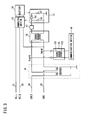
- FIG. 1 is a diagram showing an exemplary configuration of a communication system according to Embodiment 1 of the present invention.
- FIG. 1 shows an example in which the communication system of the present invention is applied to a case in which a battery (power storage device) 10 included in a vehicle 1 such as an electric vehicle, a plug-in hybrid vehicle, or the like is supplied with power from a power supply device 2 such as a charging station.
- a battery power storage device
- the vehicle 1 and the power supply device 2 can be connected to each other by a charging cable 3.
- the charging cable 3 contains a pair of power supply lines 31 and 32 used for power supply, a grounding line (reference potential line) 33 connected to a reference potential such as a ground potential, and a control line 34 for transmitting a control signal such as a control pilot signal (CPLT) used for charging control.
- An end of the charging cable 3 is connected to the power supply device 2 side, and a plug 30 is provided on the other end of the charging cable 3.
- the plug 30 can be connected to a power receiving connector 11 provided as an in-vehicle power supply port serving as a connection site on the vehicle 1 side.
- connection terminals provided at end portions of the power supply lines 31 and 32, the grounding line 33, and the control line 34 in the charging cable 3 come into contact with connection terminals provided in the power receiving connector 11, whereby the circuit structure exemplarily shown in FIG. 1 is realized.
- the power supply lines 31 and 32 are AC lines to which AC voltage is applied.
- the control line 34 is a signal line through which a control signal such as a control pilot signal is transmitted and received, and charging control is performed based on a control signal transmitted and received when the power supply device 2 and a charging control device 13 are connected to each other.
- the grounding line 33 and the control line 34 can be also used as media for transmitting information for performing vehicle authentication, charging management, accounting management, and the like, and other various kinds of information. That is, the vehicle 1 and the power supply device 2 can communicate with each other by superposing and separating a communication signal on and from the grounding line 33 and the control line 34 as media.
- the power supply device 2 includes a power supply device 20 that supplies AC power, a charging control device 21 that performs communication regarding charging control, a communication device 22 that transmits and receives a communication signal, a superposition/separation unit 23 that superposes and separates the communication signal on and from the grounding line 33 and the control line 34, a common mode choke coil 24 using a pair of induction elements, and a low-pass filter 25 that blocks the communication signal.
- One ends of the power supply lines 31 and 32 and the grounding line 33 are connected to the power supply section 20.
- One end of the control line 34 and the grounding line 33 are connected to the charging control device 21.
- Lines inside the power supply device 2 are internal conducting wires that act as extended lines connected to the power supply lines 31 and 32, the grounding line 33, and the control line 34 which are contained in the charging cable 3 provided outside the power supply device 2.
- the lines inside the power supply device 2 including the extended line portions provided as the internal conducting wires, will be described as the power supply lines 31 and 32, the grounding line 33, and the control line 34.
- the charging control device 21 is, for example, an output-side circuit complying with the international standard regarding charging control, and performs charging control in various states such as confirmation of connection, start of energization, and the like by transmitting and receiving a control signal such as a control pilot signal.
- the charging control device 21 includes various elements such as a capacitor C2, a resistor R2, and the like, and various circuits such as an oscillation circuit O and the like.
- the parameters of the various elements such as the capacitor C2 and the resistor R2 are appropriately designed in view of the frequency band of the control signal to be transmitted and received, and the like. For example, when a control pilot signal having a rectangular wave of 1 kHz is used as a control signal, a capacitor C2 of 2.2 nF and a resistor R2 of 1.0 k ⁇ are used.
- the communication device 22 is connected to a branch line 35a branched from the grounding line 33 and a branch line 35b branched from the control line 34 via the superposition/separation unit 23, and transmits and receives the communication signal by using the grounding line 33 and the control line 34 as media.
- the superposition/separation unit 23 is connected to the branch line 35a branched from the grounding line 33 and the branch line 35b branched from the control line 34 via coupling capacitors.
- Each coupling capacitor has a high impedance for the control signal, and a low impedance for the communication signal.
- a capacitor having a capacitance of 1 nF is used as an example of the coupling capacitor.
- the superposition/separation unit 23 is a circuit such as a coupling transformer (an electromagnetic guidance type signal converter) including a first coil 231 having both ends connected to the grounding line 33 and the control line 34 via the respective branch lines 35a and 35b, and a second coil 232 electromagnetically coupled to the first coil 231.
- the second coil 232 is connected to the communication device 22.
- the superposition/separation unit 23 superposes various communication signals on the grounding line 33 and the control line 34, and separates superposed various communication signals.
- the superposition/separation unit 23 superposes various communication signals output from the communication device 22, and inputs separated various communication signals to the communication device 22, the communication device 22 is allowed to perform communication.
- Each communication signal is transmitted and received as an electromagnetic wave superposed on carriers (subcarriers).
- carriers subcarriers.
- the control signal is output from an oscillator of 1 kHz, the control signal is a signal of a lower frequency than the communication signal.
- the common mode choke coil 24 is interposed in the grounding line 33 and the control line 34, and is located between the charging control device 21, and branch portions 35a1 and 35b1 of the two branch lines 35a and 35b connected to the communication device 22 via the superposition/separation unit 23.
- the common mode choke coil 24 has a high impedance for common mode noise generated in the grounding line 33 and the control line 34.
- the low-pass filter 25 is interposed in the control line 34.
- the low-pass filter 25 acts as a blocking section that transmits signals in a frequency band lower than a predetermined frequency, e.g., a signal in a frequency band used for the control signal, and blocks highfrequency communication signals.
- the low-pass filter 25 is located between the charging control device 21 and the common mode choke coil 24.
- the common mode choke coil 24 may be located between the charging control device 21 and the low-pass filter 25.
- the charging control device 21, the common mode choke coil 24, and the low-pass filter 25 are shown as separated components.
- the charging control device 21 may include the common mode choke coil 24 and the low-pass filter 25.
- the common mode choke coil 24 and the low-pass filter 25 may be integrated with each other inside or outside the charging control device 21.
- the vehicle 1 includes, in addition to the battery 10 and the power receiving connector 11, a charging device 12 that charges the battery, the charging control device 13 that performs communication regarding charging control, a communication device 14 that transmits and receives a communication signal, a superposition/separation unit 15 that superposes and separates the communication signal on and from the grounding line 33 and the control line 34, a common mode choke coil 16 using a pair of induction elements, and a low-pass filter 17 that blocks the communication signal.
- connection terminals provided at the other ends of the power supply lines 31 and 32, the other end of the grounding line 33, and the other end of the control line 34, which are contained in the charging cable 3, are connected to the connection terminals provided in the power receiving connector 11.
- the power receiving connector 11 includes internal lines connected to the power supply lines 31 and 32, the grounding line 33, and the control line 34 via the connection terminals.
- the other ends of the internal lines connected to the power supply lines 31 and 32 are connected to the charging device 12 via AC lines provided inside the vehicle 1, whereby the battery 10 is charged by the charging device 12.
- the other end of the internal line connected to the grounding line 33 is connected to the charging device 12, the charging control device 13, and the battery 10 via an internal line in the vehicle 1 or a body earth.
- the other end of the internal line connected to the control line 34 is connected to the charging control device 13 via an extended line provided as an internal line in the vehicle 1.
- the respective internal lines including the AC lines and the extended lines, will be described as the power supply lines 31 and 32, the grounding line 33, and the control line 34.
- the charging control device 13 is, for example, an input-side circuit complying with the international standard regarding charging control, and performs charging control in various states such as confirmation of connection, start of energization, and the like, by transmitting and receiving a control signal such as a control pilot signal, when the charging control device 13 becomes communicable with the charging control device 21 of the power supply device 2.
- the charging control device 13 includes various elements such as a capacitor C1, a resistor R1, a diode Vd, and the like.
- the parameters of the various elements such as the capacitor C1 and the resistor R1 are appropriately designed in view of the frequency band regarding the control signal to be transmitted and received, or the like. For example, when a control pilot signal having a rectangular wave of 1 kHz is used as a control signal, a capacitor C2 of 1.8 nF and a resistor R2 of 2.74 k ⁇ are used.
- the communication device 14 is connected to a branch line 36a branched from the grounding line 33 and a branch line 36b branched from the control line 34 via the superposition/separation unit 15, and transmits and receives the communication signal by using the grounding line 33 and the control line 34 as media.
- the superposition/separation unit 15 is connected to the branch line 36a branched from the grounding line 33 and the branch line 36b branched from the control line 34 via coupling capacitors.
- Each coupling capacitor has a high impedance for the control signal, and a low impedance for the communication signal.
- a capacitor having a capacitance of 1 nF is used as an example of the coupling capacitor.
- the superposition/separation unit 15 is a circuit such as a coupling transformer including a first coil 151 having both ends connected to the grounding line 33 and the control line 34 via the respective branch lines 36a and 36b, and a second coil 152 electromagnetically coupled to the first coil 151.
- the second coil 152 is connected to the communication device 14.
- the superposition/separation unit 15 superposes various communication signals on the grounding line 33 and the control line 34, and separates superposed various communication signals.
- the superposition/separation unit 15 superposes various communication signals output from the communication device 14, and inputs separated various communication signals to the communication device 14, the communication device 14 is allowed to perform communication.
- the common mode choke coil 16 is interposed in the grounding line 33 and the control line 34, and is located between the charging control device 13, and branch portions 36a1 and 36b1 of the two branch lines 36a and 36b connected to the communication device 14 via the superposition/separation unit 16.
- the common mode choke coil 16 has a high impedance for common mode noise generated in the grounding line 33 and the control line 34.
- the low-pass filter 17 is interposed in the control line 34.
- the low-pass filter 17 acts as a blocking section that transmits signals in a frequency band lower than a predetermined frequency, e.g., a signal in a frequency band used for the control signal, and blocks highfrequency communication signals.
- the low-pass filter 17 is positioned between the charging control device 13 and the common mode choke coil 16.
- the common mode choke coil 16 may be located between the charging control device 13 and the low-pass filter 17.
- the charging control device 13 the common mode choke coil 16, and the low-pass filter 17 are shown as separated components.
- the charging control device 13 may include the common mode choke coil 16 and the low-pass filter 17.
- the common mode choke coil 16 and the low-pass filter 17 may be integrated with each other inside or outside the charging control device 13.
- a loop circuit for transmitting a communication signal is formed by the superposition/separation unit 15, the grounding line 33, the control line 34, the superposition/separation unit 23, and other lines, elements, and circuits.
- inband communication in which a communication signal is superposed on the grounding line 33 and the control line 34 is realized between the communication device 14 in the vehicle 1 and the communication device 22 in the power supply device 2.
- FIG. 2 is a circuit diagram showing examples of the common mode choke coils 16 and 24 and the low-pass filters 17 and 25 used in the communication system according to Embodiment 1 of the present invention.
- FIG. 2 shows the common mode choke coil 16, the low-pass filter 17, and the charging control device 13 included in the vehicle 1 shown in FIG. 1 . Since the arrangement of the common mode choke coil 24, the low-pass filter 25, and the charging control device 21 included in the power supply device 2 is similar to the arrangement shown in FIG. 2 , these components will also be described with reference to FIG. 2 in which the reference numerals thereof are also shown.
- the common mode choke coil 16 (24) is configured using a pair of induction elements or an equivalent circuit thereof, and has a high impedance for common mode noise while having a low impedance for signals such as the communication signal, the control signal, and the like.
- the low-pass filter 17 (25) is, as shown in FIG. 2 , configured as a circuit in which, for example, a coil having an inductance of 1.5 mH and a resistor of 1.0 k ⁇ are arranged in parallel, or as an equivalent circuit thereof.
- the low-pass filter may be configured using another circuit as long as similar characteristics can be achieved.
- the values of the elements used in the low-pass filter are merely examples, and elements of other values may be used.
- FIG. 3 is a circuit diagram showing an example of a simulation of common mode noise in the communication system according to Embodiment 1 of the present invention.
- FIG. 3 shows an equivalent circuit for a BCI test executed as an evaluation test for common mode noise on the vehicle 1 side of the communication system shown in FIG. 1 .
- the evaluation test such as the BCI test
- common mode noise is applied from a probe as a noise generation source to the grounding line 33 and the control line 34.
- reference numeral 4 denotes a simulation noise source which is an equivalent circuit of a noise generation source using a probe, and the simulation noise source 4 applies in-phase common mode noises to the grounding line 33 and the control line 34.
- Voltages Vgnd and Vcplt applied as the common mode noises from the simulation noise source 4 to the grounding line 33 and the control line 34 are in-phase signals having the same amplitude. Since the common mode choke coil 16 has a high impedance for the common mode noises, the voltages Vgnd and Vcplt applied to the grounding line 33 and the control line 34 are not likely to be adversely affected by a line impedance due to the circuit in the charging control device 13. Then, the common mode noises do not flow into the charging control device 13, but flow from the both ends of the first coil 151 into the superposition/separation unit 15, as in-phase signals having substantially the same amplitude.
- the common mode noises are applied to the superposition/separation unit 15 without being changed into normal mode noises.
- the common mode noises flowing from the both ends of the first coil 151 are the in-phase signals having substantially the same amplitude, and therefore, cancel out each other in the first coil 151 and do not flow into the communication device 14. Accordingly, it is possible to prevent occurrence of abnormality such as false operation due to flow of noise into the communication device 14.
- a situation similar to above occurs on the power supply device 2 side, and it is possible to prevent occurrence of abnormality such as false operation due to flow of noise into the communication device 22.
- Embodiment 2 a common mode choke coil is added to the power receiving connector of Embodiment 1.
- Embodiment 1 is supposed to be referred to, and therefore, description thereof will be omitted.
- FIG. 4 is a diagram showing an exemplary configuration of a communication system according to Embodiment 2 of the present invention.
- FIG. 4 shows a configuration obtained by adding a common mode choke coil 18 to the communication system according to Embodiment 1 shown in FIG. 1 .
- the common mode choke coil 18 using a pair of induction elements is incorporated in a casing of the power receiving connector 11.
- the common mode choke coil 18 is interposed in the internal lines connected to the grounding line 33 and the control line 34.
- the common mode choke coil 18 incorporated in the power receiving connector 11 has a high impedance for common mode noise generated in the grounding line 33 and the control line 34, and therefore, resistance to the common mode noise can be enhanced as compared to Embodiment 1.
- the common mode choke coil 18 may be provided outside the casing of the power receiving connector 11 as long as it is integrated with the power receiving connector 11.
- a loop circuit for transmitting a communication signal is formed by the superposition/separation unit 15, the grounding line 33, the control line 34, the superposition/separation unit 23, and other lines, elements, and circuits.
- inband communication in which the communication signal is superposed on the grounding line 33 and the control line 34 is realized between the communication device 14 in the vehicle 1 and the communication device 22 in the power supply device 2.
- Embodiment 3 provides a configuration in which the common mode choke coil located between the charging control device and the branch portions 36a1 and 36b1 of the two branch lines 36a and 36b connected to the communication device via the superposition/separation unit, is omitted from Embodiment 2.
- Embodiment 1 or 2 is supposed to be referred to, and therefore, description thereof will be omitted.
- FIG. 5 is a diagram showing an exemplary configuration of a communication system according to Embodiment 3 of the present invention.
- FIG. 5 shows a configuration obtained by omitting the common mode choke coil 16 in the communication system of Embodiment 2 shown in FIG 4 .
- a common mode choke coil 18 using a pair of induction elements is incorporated in the casing of the power receiving connector 11.
- the common mode choke coil 18 is interposed in the internal lines connected to the grounding line 33 and the control line 34.
- the common mode choke coil 18 incorporated in the power receiving connector 11 has a high impedance for common mode noise generated in the grounding line 33 and the control line 34, and therefore, suppresses the common mode noise that flows into the vehicle 1.
- the common mode choke coil 18 prevents the common mode noise generated in the device in the vehicle 1 from flowing out of the vehicle 1.
- the common mode choke coil 18 may be provided outside the casing of the power receiving connector 11 as long as it is integrated with the power receiving connector 11.
- the low-pass filter 17 may be integrated with the power receiving connector 11.
- a loop circuit for transmitting a communication signal is formed by the superposition/separation unit 15, the grounding line 33, the control line 34, the superposition/separation unit 23, and other lines, elements, and circuits.
- inband communication in which the communication signal is superposed on the grounding line 33 and the control line 34 is realized between the communication device 14 in the vehicle 1 and the communication device 22 in the power supply device 2.
- Embodiments 1 to 3 are merely disclosure of part of infinite number of examples of the present invention, and can be appropriately designed by adding various factors such as the purpose, usage, mode, and the like.
- the communication device is connected to the branch lines branched from the control line and the grounding line via the superposition/separation unit.
- the superposition/separation unit or the like may be interposed in the control line or the like, and the communication device or the like may be connected to the interposed superposition/separation unit or the like.
- the common mode choke coil is provided on both the power supply device side and the vehicle side.
- the common mode choke coil may be provided on one of the power supply device side and the vehicle side.
- the superposition/separation unit and/or the coupling capacitors provided on the respective branch lines may be incorporated in the communication device.
- the present invention is also applicable to, for example, a system regarding charging of an object to be charged other than batteries included in vehicles.
- the present invention can be developed into various modes.
Landscapes
- Engineering & Computer Science (AREA)
- Power Engineering (AREA)
- Computer Networks & Wireless Communication (AREA)
- Mechanical Engineering (AREA)
- Transportation (AREA)
- Signal Processing (AREA)
- Electrochemistry (AREA)
- General Chemical & Material Sciences (AREA)
- Chemical Kinetics & Catalysis (AREA)
- Chemical & Material Sciences (AREA)
- Manufacturing & Machinery (AREA)
- Charge And Discharge Circuits For Batteries Or The Like (AREA)
- Electric Propulsion And Braking For Vehicles (AREA)
- Secondary Cells (AREA)
- Devices For Checking Fares Or Tickets At Control Points (AREA)
- Cable Transmission Systems, Equalization Of Radio And Reduction Of Echo (AREA)
Abstract
Description
- The present invention relates to: a communication system in which a control line for transmitting a control signal used for control of charging of an object to be charged and a reference potential line connected to a reference potential are used as media, and a communication signal different from the control signal is transmitted via the media to perform communication; a charging control device used in the communication system; a vehicle including the charging control device; and a power supply device including the charging control device.
- In recent years, electric vehicles and hybrid vehicles are beginning to prevail, which include devices such as motors and batteries, and travel by driving the motors with power stored in the batteries. The electric vehicles charge their batteries with power supplied from external power supply devices. As for the hybrid vehicles, plug-in hybrid vehicles have been practically used, which allow their batteries to be charged by external power supply devices. The external power supply devices are power supply devices installed in ordinary houses or facilities such as commercial charging stations. When a power supply device supplies power to a vehicle, a plug at an end of a charging cable connected to the power supply device is connected to a power supply port which is provided in the vehicle as a power receiving connector. Then, power is supplied from the power supply device to the vehicle via a power supply line contained in the charging cable, and thereby the battery is charged.
- Not only the power supply line but also other lines such as a grounding line, a control line, and the like are contained in the charging cable. The control line is a line used for transmission of a control signal such as a control pilot signal or the like used for control of power supply to the power storage device. By transmitting and receiving the control signal between the power supply device and the vehicle via the control line, various states are detected such as the connection state of the charging cable, whether charging is possible or not, the state of charging, and the like, and charging control is performed according to the detected states.
- Further, for practical use of vehicles that need external power supply, such as electric vehicles and hybrid vehicles, a communication function is required, which allows a vehicle and a power supply device to transmit and receive information for power supply control, and communication information for management of the amount of power, accounting, or the like.
- Thus, standardization of communication such as inband communication has been progressed, in which a communication signal is superposed on a control signal to be transmitted and received between a vehicle and a power supply device (refer to Non-Patent Literature 1, for example).
-
FIG. 6 is an illustrative diagram showing an exemplary configuration of a system standardization of which is in progress. InFIG 6 ,reference numeral 1000 denotes a vehicle. When thevehicle 1000 is supplied with power from apower supply device 2000, thevehicle 1000 is connected to thepower supply device 2000 via acharging cable 3000. Thecharging cable 3000 contains a pair ofpower supply lines grounding line 3003 which is a conducting wire for grounding, and acontrol line 3004 for transmitting a control signal such as a control pilot signal (CPLT) used for charging control. - An end of the
charging cable 3000 is connected to thepower supply device 2000 side, and aplug 3005 is provided on the other end of thecharging cable 3000. Theplug 3005 is connected to apower receiving connector 1001 provided as a connection part at a power supply port on thevehicle 1000 side, and thereby power supply is enabled. - The
power supply device 2000 includes apower supply section 2001 that supplies AC power, acharging control device 2002 that performs communication regarding charging control, acommunication device 2003 that transmits and receives a communication signal, and a superposition/separation unit 2004 that performs superposition and separation of the communication signal on and from thegrounding line 3003 and thecontrol line 3004. - The
charging control device 2002 includes various elements such as a capacitor C2, a resistor R2, and the like and various circuits such as an oscillation circuit O and the like. The capacitor C2 and the oscillation circuit O are connected to a ground potential. - The superposition/
separation unit 2004 includes afirst coil 2004a having both ends connected to thegrounding line 3003 and thecontrol line 3004, and asecond coil 2004b having both ends connected to thecommunication device 1005. Thefirst coil 2004a and thesecond coil 2004b are electromagnetically coupled to each other. - The superposition/
separation unit 2004 superposes various communication signals on thegrounding line 3003 and thecontrol line 3004, and separates superposed various communication signals. When the superposition/separation unit 2004 superposes various communication signals output from thecommunication device 2003, and inputs separated various communication signals to thecommunication device 2003, thecommunication device 2003 is allowed to perform communication. - The
vehicle 1000 includes thepower receiving connector 1001, abattery 1002, acharging device 1003 that charges thebattery 1002, acharging control device 1004 that performs communication regarding charging control, acommunication device 1005 that transmits and receives communication signals, and a superposition/separation unit 1006 that performs superposition and separation of the communication signals on and from thegrounding line 3003 and thecontrol line 3004. - The
charging control device 1004 includes various elements such as a capacitor C1, a resistor R1, a diode Vd, and the like. The capacitor C1 and the resistor R2 are connected to the grounding potential. - The superposition/
separation unit 1006 includes afirst coil 1006a having both ends connected to thegrounding line 3003 and thecontrol line 3004, and asecond coil 1006b having both ends connected to thecommunication device 1005. Thefirst coil 1006a and thesecond coil 1006b are electromagnetically coupled to each other. - The superposition/
separation unit 1006 superposes various communication signals on thegrounding line 3003 and thecontrol line 3004, and separates superposed various communication signals. When the superposition/separation unit 1006 superposes various communication signals output from thecommunication device 1005, and inputs separated various communication signals to thecommunication device 1005, thecommunication device 1005 is allowed to perform communication. - NON PATENT LITERATURE 1: "SURFACE VEHICLE RECOMMENDED PRACTICE", J1772 JAN2010, Society of Automotive Engineers, Inc., October, 1996 (revised in January, 2010)
- In the conventional system exemplified in
FIG 6 , however, common mode noise generated in thegrounding line 3003 and thecontrol line 3004 may flow into thecommunication device 1005 or thecommunication device 2003 and cause abnormality such as false operation. -
FIG. 7 is a circuit diagram showing an example of a simulation of common mode noise.FIG. 7 shows an equivalent circuit for a BCI test executed as an evaluation test for common mode noise on thevehicle 1000 side of the system shown inFIG. 6 . In the evaluation test such as the BCI test, common mode noise is applied from a probe as a noise generation source to thegrounding line 3003 and thecontrol line 3004. InFIG. 7 ,reference numeral 4000 denotes a simulation noise source which is an equivalent circuit of a noise generation source using a probe. Thesimulation noise source 4000 applies in-phase common mode noises to thegrounding line 3003 and thecontrol line 3004. - Voltages Vgnd and Vcplt applied as the common mode noises from the
simulation noise source 4000 to thegrounding line 3003 and thecontrol line 3004 are originally in-phase signals having the same amplitude, and therefore, cancel out each other in thefirst coil 1006a of the superposition/separation unit 1006 and do not flow into thecommunication device 1005. - However, in the
charging control device 1004, a difference occurs between the voltage Vgnd on thegrounding line 3003 side and the voltage Vcplt on thecontrol line 3004 due to the noise that flows out via the ground (GND), resulting in an imbalance state. The imbalance between thegrounding line 3003 side and thecontrol line 3004 side based on the circuit structure in thecharging control device 1004 also leads to a difference in line impedance. As a result, the common mode noises applied to thegrounding line 3003 and thecontrol line 3004 change into normal mode noises. The normal mode noises do not cancel out each other in thefirst coil 1006a of the superposition/separation unit 1006, and flows into thecommunication device 1005, which may cause abnormality such as false operation. A similar situation may occur in thecommunication device 2003 on thepower supply device 2000 side. - The present invention has been made in view of the above situation. A major object of the present invention is to provide a communication system, a charging control device, a vehicle, and a power supply device which suppress common mode noise by interposing a pair of induction elements in the control line and the grounding line.
- Furthermore, another object of the present invention is to provide a communication system, a charging control device, a vehicle, and a power supply device which prevent common mode noise from changing into normal mode noise to eliminate adverse effects on a communication device and the like, by providing a pair of induction elements in front of the charging control device.
- A communication system according to the present invention is a communication system in which a control line for transmitting a control signal used for control of charging of an object to be charged and a reference potential line connected to a reference potential are used as media, and a communication signal different from the control signal is transmitted via the media to perform communication. The communication system includes: a charging control device connected to the control line and the reference potential line, and configured to control charging in accordance with the control signal; a communication device connected to two branch lines branched from the control line and the reference potential line, respectively, and configured to perform communication by the communication signal; and a pair of induction elements interposed in the control line and the reference potential line.
- In the communication system according to the present invention, the pair of induction elements is located between the charging control device and branch portions of the two branch lines.
- In the communication system according to the present invention, the pair of induction elements is a common mode choke coil.
- In the communication system according to the present invention, a power storage device as the object to be charged, the charging control device, the communication device, and the pair of induction elements are provided in a vehicle.
- In the communication system according to the present invention, the vehicle includes a connector for connecting an external line to the control line and the reference potential line, and the pair of induction elements is provided in the connector.
- In the communication system according to the present invention, the charging control device, the communication device, and the pair of induction elements are provided in a power supply device configured to supply power to the object to be charged.
- A charging control device according to the present invention is a charging control device connected to a control line for transmitting a control signal used for control of charging of an object to be charged and to a reference potential line connected to a reference potential, and configured to control charging in accordance with the control signal. The charging control device includes a pair of induction elements connected to the control line and the reference potential line.
- A vehicle according to the present invention includes: a power storage device; a charging control device connected to a control line for transmitting a control signal used for control of charging of the power storage device and to a reference potential line connected to a reference potential, and configured to control charging in accordance with the control signal; a communication device connected to two branch lines branched from the control line and the reference potential line, respectively, and configured to perform communication by transmitting a communication signal different from the control signal; and a pair of induction elements interposed in the control line and the reference potential line.
- The vehicle according to the present invention includes a connector for connecting an external line to the control line and the reference potential line, and the pair of induction elements is provided in the connector.
- A power supply device according to the present invention is configured to supply power to an object to be charged, and includes: a charging control device connected to a control line for transmitting a control signal used for control of charging of the object to be charged and to a reference potential line connected to a reference potential, and configured to control charging in accordance with the control signal; a communication device connected to two branch lines branched from the control line and the reference potential line, respectively, and configured to perform communication by transmitting a communication signal different from the control signal; and a pair of induction elements interposed in the control line and the reference potential line.
- In the present invention, common mode noise is suppressed by providing the pair of induction elements having a high impedance for the common mode noise.
- Particularly when the pair of induction elements is provided between the charging control device and branch portions of the two branch lines, common mode noise is prevented from changing into normal mode noise due to influence of a device such as the charging control device.
- In the present invention, the pair of induction elements has a high impedance for common mode noise, and therefore, prevents entry of the common mode noise, resulting in advantageous effects such as that the common mode noise can be suppressed.
- Further, in the present invention, since the pair of induction elements has a high impedance for common mode noise, a voltage applied to the grounding line and a voltage applied to the control line are balanced. Therefore, the common mode noise is not changed into normal mode noise, and the voltages of signals applied as the common mode noise to the both ends of the coil cancel out each other. Accordingly, advantageous effects are obtained such as that the noise can be prevented from flowing into the communication device.
-
- [
FIG. 1] FIG. 1 is a diagram showing an exemplary configuration of a communication system according to Embodiment 1 of the present invention. - [
FIG. 2] FIG. 2 is a circuit diagram showing examples of a common mode choke coil and a low-pass filter used in the communication system according to Embodiment 1 of the present invention. - [
FIG. 3] FIG. 3 is a circuit diagram showing an example of a simulation of common mode noise in the communication system according to Embodiment 1 of the present invention. - [
FIG. 4] FIG. 4 is a diagram showing an exemplary configuration of a communication system according toEmbodiment 2 of the present invention. - [
FIG. 5] FIG. 5 is a diagram showing an exemplary configuration of a communication system according toEmbodiment 3 of the present invention. - [
FIG. 6] FIG 6 is a diagram showing an exemplary configuration of a system, standardization of which is in progress. - [
FIG. 7] FIG. 7 is a circuit diagram showing an example of a simulation of common mode noise. - Hereinafter, the present invention will be described in detail with reference to the drawings showing embodiments thereof.
-
FIG. 1 is a diagram showing an exemplary configuration of a communication system according to Embodiment 1 of the present invention.FIG. 1 shows an example in which the communication system of the present invention is applied to a case in which a battery (power storage device) 10 included in a vehicle 1 such as an electric vehicle, a plug-in hybrid vehicle, or the like is supplied with power from apower supply device 2 such as a charging station. - The vehicle 1 and the
power supply device 2 can be connected to each other by a chargingcable 3. The chargingcable 3 contains a pair ofpower supply lines control line 34 for transmitting a control signal such as a control pilot signal (CPLT) used for charging control. An end of the chargingcable 3 is connected to thepower supply device 2 side, and aplug 30 is provided on the other end of the chargingcable 3. Theplug 30 can be connected to apower receiving connector 11 provided as an in-vehicle power supply port serving as a connection site on the vehicle 1 side. When theplug 30 at the other end of the chargingcable 3 is connected to thepower receiving connector 11, connection terminals provided at end portions of thepower supply lines grounding line 33, and thecontrol line 34 in the chargingcable 3 come into contact with connection terminals provided in thepower receiving connector 11, whereby the circuit structure exemplarily shown inFIG. 1 is realized. - The
power supply lines control line 34 is a signal line through which a control signal such as a control pilot signal is transmitted and received, and charging control is performed based on a control signal transmitted and received when thepower supply device 2 and a chargingcontrol device 13 are connected to each other. In addition, thegrounding line 33 and thecontrol line 34 can be also used as media for transmitting information for performing vehicle authentication, charging management, accounting management, and the like, and other various kinds of information. That is, the vehicle 1 and thepower supply device 2 can communicate with each other by superposing and separating a communication signal on and from thegrounding line 33 and thecontrol line 34 as media. - The
power supply device 2 includes apower supply device 20 that supplies AC power, a chargingcontrol device 21 that performs communication regarding charging control, acommunication device 22 that transmits and receives a communication signal, a superposition/separation unit 23 that superposes and separates the communication signal on and from thegrounding line 33 and thecontrol line 34, a commonmode choke coil 24 using a pair of induction elements, and a low-pass filter 25 that blocks the communication signal. - One ends of the
power supply lines grounding line 33 are connected to thepower supply section 20. One end of thecontrol line 34 and thegrounding line 33 are connected to the chargingcontrol device 21. Lines inside thepower supply device 2 are internal conducting wires that act as extended lines connected to thepower supply lines grounding line 33, and thecontrol line 34 which are contained in the chargingcable 3 provided outside thepower supply device 2. However, in the following description, for convenience sake, the lines inside thepower supply device 2, including the extended line portions provided as the internal conducting wires, will be described as thepower supply lines grounding line 33, and thecontrol line 34. - The charging
control device 21 is, for example, an output-side circuit complying with the international standard regarding charging control, and performs charging control in various states such as confirmation of connection, start of energization, and the like by transmitting and receiving a control signal such as a control pilot signal. - The charging
control device 21 includes various elements such as a capacitor C2, a resistor R2, and the like, and various circuits such as an oscillation circuit O and the like. The parameters of the various elements such as the capacitor C2 and the resistor R2 are appropriately designed in view of the frequency band of the control signal to be transmitted and received, and the like. For example, when a control pilot signal having a rectangular wave of 1 kHz is used as a control signal, a capacitor C2 of 2.2 nF and a resistor R2 of 1.0 kΩ are used. - The
communication device 22 is connected to abranch line 35a branched from thegrounding line 33 and abranch line 35b branched from thecontrol line 34 via the superposition/separation unit 23, and transmits and receives the communication signal by using thegrounding line 33 and thecontrol line 34 as media. - The superposition/
separation unit 23 is connected to thebranch line 35a branched from thegrounding line 33 and thebranch line 35b branched from thecontrol line 34 via coupling capacitors. Each coupling capacitor has a high impedance for the control signal, and a low impedance for the communication signal. As an example of the coupling capacitor, a capacitor having a capacitance of 1 nF is used. - The superposition/
separation unit 23 is a circuit such as a coupling transformer (an electromagnetic guidance type signal converter) including afirst coil 231 having both ends connected to thegrounding line 33 and thecontrol line 34 via therespective branch lines second coil 232 electromagnetically coupled to thefirst coil 231. Thesecond coil 232 is connected to thecommunication device 22. - The superposition/
separation unit 23 superposes various communication signals on thegrounding line 33 and thecontrol line 34, and separates superposed various communication signals. When the superposition/separation unit 23 superposes various communication signals output from thecommunication device 22, and inputs separated various communication signals to thecommunication device 22, thecommunication device 22 is allowed to perform communication. - Each communication signal is transmitted and received as an electromagnetic wave superposed on carriers (subcarriers). As for the frequency bands used for the carriers regarding the communication signal, a frequency band ranging from several 10 kHz to several 100 kHz, e.g., from 30 kHz to 450 kHz, is used for low-speed communication, and a frequency band ranging from several MHz to several 10 MHz, e.g., from 2 MHz to 30 MHz, is used for high-speed communication. Since the control signal is output from an oscillator of 1 kHz, the control signal is a signal of a lower frequency than the communication signal.
- The common
mode choke coil 24 is interposed in thegrounding line 33 and thecontrol line 34, and is located between the chargingcontrol device 21, and branch portions 35a1 and 35b1 of the twobranch lines communication device 22 via the superposition/separation unit 23. The commonmode choke coil 24 has a high impedance for common mode noise generated in thegrounding line 33 and thecontrol line 34. - The low-
pass filter 25 is interposed in thecontrol line 34. The low-pass filter 25 acts as a blocking section that transmits signals in a frequency band lower than a predetermined frequency, e.g., a signal in a frequency band used for the control signal, and blocks highfrequency communication signals. - In
FIG 1 , the low-pass filter 25 is located between the chargingcontrol device 21 and the commonmode choke coil 24. However, the commonmode choke coil 24 may be located between the chargingcontrol device 21 and the low-pass filter 25. - Further, in
FIG. 1 , the chargingcontrol device 21, the commonmode choke coil 24, and the low-pass filter 25 are shown as separated components. However, the chargingcontrol device 21 may include the commonmode choke coil 24 and the low-pass filter 25. For example, the commonmode choke coil 24 and the low-pass filter 25 may be integrated with each other inside or outside the chargingcontrol device 21. - The vehicle 1 includes, in addition to the
battery 10 and thepower receiving connector 11, a chargingdevice 12 that charges the battery, the chargingcontrol device 13 that performs communication regarding charging control, acommunication device 14 that transmits and receives a communication signal, a superposition/separation unit 15 that superposes and separates the communication signal on and from thegrounding line 33 and thecontrol line 34, a commonmode choke coil 16 using a pair of induction elements, and a low-pass filter 17 that blocks the communication signal. - When the plug of the charging
cable 3 is connected to thepower receiving connector 11 of the vehicle 1, connection terminals provided at the other ends of thepower supply lines grounding line 33, and the other end of thecontrol line 34, which are contained in the chargingcable 3, are connected to the connection terminals provided in thepower receiving connector 11. - The
power receiving connector 11 includes internal lines connected to thepower supply lines grounding line 33, and thecontrol line 34 via the connection terminals. The other ends of the internal lines connected to thepower supply lines device 12 via AC lines provided inside the vehicle 1, whereby thebattery 10 is charged by the chargingdevice 12. The other end of the internal line connected to thegrounding line 33 is connected to the chargingdevice 12, the chargingcontrol device 13, and thebattery 10 via an internal line in the vehicle 1 or a body earth. The other end of the internal line connected to thecontrol line 34 is connected to the chargingcontrol device 13 via an extended line provided as an internal line in the vehicle 1. In the following description, the respective internal lines, including the AC lines and the extended lines, will be described as thepower supply lines grounding line 33, and thecontrol line 34. - The charging
control device 13 is, for example, an input-side circuit complying with the international standard regarding charging control, and performs charging control in various states such as confirmation of connection, start of energization, and the like, by transmitting and receiving a control signal such as a control pilot signal, when the chargingcontrol device 13 becomes communicable with the chargingcontrol device 21 of thepower supply device 2. - The charging
control device 13 includes various elements such as a capacitor C1, a resistor R1, a diode Vd, and the like. The parameters of the various elements such as the capacitor C1 and the resistor R1 are appropriately designed in view of the frequency band regarding the control signal to be transmitted and received, or the like. For example, when a control pilot signal having a rectangular wave of 1 kHz is used as a control signal, a capacitor C2 of 1.8 nF and a resistor R2 of 2.74 kΩ are used. - The
communication device 14 is connected to abranch line 36a branched from thegrounding line 33 and abranch line 36b branched from thecontrol line 34 via the superposition/separation unit 15, and transmits and receives the communication signal by using thegrounding line 33 and thecontrol line 34 as media. - The superposition/
separation unit 15 is connected to thebranch line 36a branched from thegrounding line 33 and thebranch line 36b branched from thecontrol line 34 via coupling capacitors. Each coupling capacitor has a high impedance for the control signal, and a low impedance for the communication signal. As an example of the coupling capacitor, a capacitor having a capacitance of 1 nF is used. - The superposition/
separation unit 15 is a circuit such as a coupling transformer including afirst coil 151 having both ends connected to thegrounding line 33 and thecontrol line 34 via therespective branch lines second coil 152 electromagnetically coupled to thefirst coil 151. Thesecond coil 152 is connected to thecommunication device 14. - The superposition/
separation unit 15 superposes various communication signals on thegrounding line 33 and thecontrol line 34, and separates superposed various communication signals. When the superposition/separation unit 15 superposes various communication signals output from thecommunication device 14, and inputs separated various communication signals to thecommunication device 14, thecommunication device 14 is allowed to perform communication. - The common
mode choke coil 16 is interposed in thegrounding line 33 and thecontrol line 34, and is located between the chargingcontrol device 13, and branch portions 36a1 and 36b1 of the twobranch lines communication device 14 via the superposition/separation unit 16. The commonmode choke coil 16 has a high impedance for common mode noise generated in thegrounding line 33 and thecontrol line 34. - The low-
pass filter 17 is interposed in thecontrol line 34. The low-pass filter 17 acts as a blocking section that transmits signals in a frequency band lower than a predetermined frequency, e.g., a signal in a frequency band used for the control signal, and blocks highfrequency communication signals. - In
FIG. 1 , the low-pass filter 17 is positioned between the chargingcontrol device 13 and the commonmode choke coil 16. However, the commonmode choke coil 16 may be located between the chargingcontrol device 13 and the low-pass filter 17. - Further, in
FIG 1 , the chargingcontrol device 13, the commonmode choke coil 16, and the low-pass filter 17 are shown as separated components. However, the chargingcontrol device 13 may include the commonmode choke coil 16 and the low-pass filter 17. For example, the commonmode choke coil 16 and the low-pass filter 17 may be integrated with each other inside or outside the chargingcontrol device 13. - By configuring the communication system of the present invention as shown in
FIG. 1 , a loop circuit for transmitting a communication signal is formed by the superposition/separation unit 15, thegrounding line 33, thecontrol line 34, the superposition/separation unit 23, and other lines, elements, and circuits. Thereby, inband communication in which a communication signal is superposed on thegrounding line 33 and thecontrol line 34 is realized between thecommunication device 14 in the vehicle 1 and thecommunication device 22 in thepower supply device 2. -
FIG. 2 is a circuit diagram showing examples of the common mode choke coils 16 and 24 and the low-pass filters FIG. 2 shows the commonmode choke coil 16, the low-pass filter 17, and the chargingcontrol device 13 included in the vehicle 1 shown inFIG. 1 . Since the arrangement of the commonmode choke coil 24, the low-pass filter 25, and the chargingcontrol device 21 included in thepower supply device 2 is similar to the arrangement shown inFIG. 2 , these components will also be described with reference toFIG. 2 in which the reference numerals thereof are also shown. - The common mode choke coil 16 (24) is configured using a pair of induction elements or an equivalent circuit thereof, and has a high impedance for common mode noise while having a low impedance for signals such as the communication signal, the control signal, and the like.
- The low-pass filter 17 (25) is, as shown in
FIG. 2 , configured as a circuit in which, for example, a coil having an inductance of 1.5 mH and a resistor of 1.0 kΩ are arranged in parallel, or as an equivalent circuit thereof. The low-pass filter may be configured using another circuit as long as similar characteristics can be achieved. In addition, the values of the elements used in the low-pass filter are merely examples, and elements of other values may be used. -
FIG. 3 is a circuit diagram showing an example of a simulation of common mode noise in the communication system according to Embodiment 1 of the present invention.FIG. 3 shows an equivalent circuit for a BCI test executed as an evaluation test for common mode noise on the vehicle 1 side of the communication system shown inFIG. 1 . In the evaluation test such as the BCI test, common mode noise is applied from a probe as a noise generation source to thegrounding line 33 and thecontrol line 34. InFIG 3 , reference numeral 4 denotes a simulation noise source which is an equivalent circuit of a noise generation source using a probe, and the simulation noise source 4 applies in-phase common mode noises to thegrounding line 33 and thecontrol line 34. - Voltages Vgnd and Vcplt applied as the common mode noises from the simulation noise source 4 to the
grounding line 33 and thecontrol line 34 are in-phase signals having the same amplitude. Since the commonmode choke coil 16 has a high impedance for the common mode noises, the voltages Vgnd and Vcplt applied to thegrounding line 33 and thecontrol line 34 are not likely to be adversely affected by a line impedance due to the circuit in the chargingcontrol device 13. Then, the common mode noises do not flow into the chargingcontrol device 13, but flow from the both ends of thefirst coil 151 into the superposition/separation unit 15, as in-phase signals having substantially the same amplitude. In other words, the common mode noises are applied to the superposition/separation unit 15 without being changed into normal mode noises. The common mode noises flowing from the both ends of thefirst coil 151 are the in-phase signals having substantially the same amplitude, and therefore, cancel out each other in thefirst coil 151 and do not flow into thecommunication device 14. Accordingly, it is possible to prevent occurrence of abnormality such as false operation due to flow of noise into thecommunication device 14. - A situation similar to above occurs on the
power supply device 2 side, and it is possible to prevent occurrence of abnormality such as false operation due to flow of noise into thecommunication device 22. - In
Embodiment 2, a common mode choke coil is added to the power receiving connector of Embodiment 1. In the following description, as for the components identical to those of Embodiment 1, Embodiment 1 is supposed to be referred to, and therefore, description thereof will be omitted. -
FIG. 4 is a diagram showing an exemplary configuration of a communication system according toEmbodiment 2 of the present invention.FIG. 4 shows a configuration obtained by adding a commonmode choke coil 18 to the communication system according to Embodiment 1 shown inFIG. 1 . In the exemplary configuration shown inFIG. 4 , the commonmode choke coil 18 using a pair of induction elements is incorporated in a casing of thepower receiving connector 11. In thepower receiving connector 11, the commonmode choke coil 18 is interposed in the internal lines connected to thegrounding line 33 and thecontrol line 34. - The common
mode choke coil 18 incorporated in thepower receiving connector 11 has a high impedance for common mode noise generated in thegrounding line 33 and thecontrol line 34, and therefore, resistance to the common mode noise can be enhanced as compared to Embodiment 1. The commonmode choke coil 18 may be provided outside the casing of thepower receiving connector 11 as long as it is integrated with thepower receiving connector 11. - By configuring the communication system of the present invention as shown in
FIG. 4 , a loop circuit for transmitting a communication signal is formed by the superposition/separation unit 15, thegrounding line 33, thecontrol line 34, the superposition/separation unit 23, and other lines, elements, and circuits. Thereby, inband communication in which the communication signal is superposed on thegrounding line 33 and thecontrol line 34 is realized between thecommunication device 14 in the vehicle 1 and thecommunication device 22 in thepower supply device 2. -
Embodiment 3 provides a configuration in which the common mode choke coil located between the charging control device and the branch portions 36a1 and 36b1 of the twobranch lines Embodiment 2. In the following description, as for the components identical to those ofEmbodiment 1 or 2,Embodiment 1 or 2 is supposed to be referred to, and therefore, description thereof will be omitted. -
FIG. 5 is a diagram showing an exemplary configuration of a communication system according toEmbodiment 3 of the present invention.FIG. 5 shows a configuration obtained by omitting the commonmode choke coil 16 in the communication system ofEmbodiment 2 shown inFIG 4 . In the exemplary configuration ofFIG. 5 , a commonmode choke coil 18 using a pair of induction elements is incorporated in the casing of thepower receiving connector 11. In thepower receiving connector 11, the commonmode choke coil 18 is interposed in the internal lines connected to thegrounding line 33 and thecontrol line 34. - The common
mode choke coil 18 incorporated in thepower receiving connector 11 has a high impedance for common mode noise generated in thegrounding line 33 and thecontrol line 34, and therefore, suppresses the common mode noise that flows into the vehicle 1. In addition, the commonmode choke coil 18 prevents the common mode noise generated in the device in the vehicle 1 from flowing out of the vehicle 1. The commonmode choke coil 18 may be provided outside the casing of thepower receiving connector 11 as long as it is integrated with thepower receiving connector 11. In addition, the low-pass filter 17 may be integrated with thepower receiving connector 11. - By configuring the communication system of the present invention as shown in
FIG. 5 , a loop circuit for transmitting a communication signal is formed by the superposition/separation unit 15, thegrounding line 33, thecontrol line 34, the superposition/separation unit 23, and other lines, elements, and circuits. Thereby, inband communication in which the communication signal is superposed on thegrounding line 33 and thecontrol line 34 is realized between thecommunication device 14 in the vehicle 1 and thecommunication device 22 in thepower supply device 2. - Embodiments 1 to 3 are merely disclosure of part of infinite number of examples of the present invention, and can be appropriately designed by adding various factors such as the purpose, usage, mode, and the like. For example, in the above embodiments, the communication device is connected to the branch lines branched from the control line and the grounding line via the superposition/separation unit. However, the superposition/separation unit or the like may be interposed in the control line or the like, and the communication device or the like may be connected to the interposed superposition/separation unit or the like. Further, in the embodiments of the present invention, the common mode choke coil is provided on both the power supply device side and the vehicle side. However, the common mode choke coil may be provided on one of the power supply device side and the vehicle side. Further, the superposition/separation unit and/or the coupling capacitors provided on the respective branch lines may be incorporated in the communication device.
- Further, the present invention is also applicable to, for example, a system regarding charging of an object to be charged other than batteries included in vehicles. Thus, the present invention can be developed into various modes.
-
- 1
- vehicle
- 10
- battery (power storage device)
- 11
- power receiving connector
- 12
- charging device
- 13
- charging control device
- 14
- communication device
- 15
- superposition/separation unit
- 151
- first coil
- 152
- second coil
- 16
- common mode choke coil (a pair of dielectric elements)
- 17
- low-pass filter
- 18
- common mode choke coil (a pair of induction elements)
- 2
- power supply device
- 20
- power supply device
- 21
- charging control device
- 22
- communication device
- 23
- superposition/separation unit
- 24
- common mode choke coil (a pair of dielectric elements)
- 25
- low-pass filter
- 3
- charging cable
- 31, 32
- power supply line
- 33
- grounding line
- 34
- control line
Claims (10)
- A communication system in which a control line for transmitting a control signal used for control of charging of an object to be charged and a reference potential line connected to a reference potential are used as media, and a communication signal different from the control signal is transmitted via the media to perform communication, the communication system comprising:a charging control device connected to the control line and the reference potential line, and configured to control charging in accordance with the control signal;a communication device connected to two branch lines branched from the control line and the reference potential line, respectively, and configured to perform communication by the communication signal; anda pair of induction elements interposed in the control line and the reference potential line.
- The communication system according to claim 1, wherein the pair of induction elements is located between the charging control device and branch portions of the two branch lines.
- The communication system according to claim 1 or 2, wherein the pair of induction elements is a common mode choke coil.
- The communication system according to any one of claims 1 to 3, wherein a power storage device as the object to be charged, the charging control device, the communication device, and the pair of induction elements are provided in a vehicle.
- The communication system according to claim 4, wherein
the vehicle includes a connector for connecting an external line to the control line and the reference potential line, and
the pair of induction elements is provided in the connector. - The communication system according to any one of claims 1 to 3, wherein the charging control device, the communication device, and the pair of induction elements are provided in a power supply device configured to supply power to the object to be charged.
- A charging control device connected to a control line for transmitting a control signal used for control of charging of an object to be charged and to a reference potential line connected to a reference potential, and configured to control charging in accordance with the control signal,
the charging control device including a pair of induction elements connected to the control line and the reference potential line. - A vehicle comprising:a power storage device;a charging control device connected to a control line for transmitting a control signal used for control of charging of the power storage device and to a reference potential line connected to a reference potential, and configured to control charging in accordance with the control signal;a communication device connected to two branch lines branched from the control line and the reference potential line, respectively, and configured to perform communication by transmitting a communication signal different from the control signal; anda pair of induction elements interposed in the control line and the reference potential line.
- The vehicle according to claim 8 further comprising a connector for connecting an external line to the control line and the reference potential line, wherein
the pair of induction elements is provided in the connector. - A power supply device configured to supply power to an object to be charged, the power supply device comprising:a charging control device connected to a control line for transmitting a control signal used for control of charging of the object to be charged and to a reference potential line connected to a reference potential, and configured to control charging in accordance with the control signal;a communication device connected to two branch lines branched from the control line and the reference potential line, respectively, and configured to perform communication by transmitting a communication signal different from the control signal; anda pair of induction elements interposed in the control line and the reference potential line.
Applications Claiming Priority (2)
| Application Number | Priority Date | Filing Date | Title |
|---|---|---|---|
| JP2012084954A JP5903993B2 (en) | 2012-04-03 | 2012-04-03 | Communications system |
| PCT/JP2013/053254 WO2013150821A1 (en) | 2012-04-03 | 2013-02-12 | Communication system, charge control apparatus, vehicle and feeding apparatus |
Publications (3)
| Publication Number | Publication Date |
|---|---|
| EP2846435A1 true EP2846435A1 (en) | 2015-03-11 |
| EP2846435A4 EP2846435A4 (en) | 2015-12-16 |
| EP2846435B1 EP2846435B1 (en) | 2018-05-30 |
Family
ID=49300322
Family Applications (1)
| Application Number | Title | Priority Date | Filing Date |
|---|---|---|---|
| EP13773137.8A Not-in-force EP2846435B1 (en) | 2012-04-03 | 2013-02-12 | Communication system, charge control apparatus, vehicle and feeding apparatus |
Country Status (5)
| Country | Link |
|---|---|
| US (1) | US20150061584A1 (en) |
| EP (1) | EP2846435B1 (en) |
| JP (1) | JP5903993B2 (en) |
| CN (1) | CN104221245B (en) |
| WO (1) | WO2013150821A1 (en) |
Cited By (4)
| Publication number | Priority date | Publication date | Assignee | Title |
|---|---|---|---|---|
| EP2733861A4 (en) * | 2011-07-13 | 2016-07-13 | Sumitomo Electric Industries | COMMUNICATION SYSTEM AND DEVICE |
| EP3220589A4 (en) * | 2014-11-14 | 2017-10-18 | Autonetworks Technologies, Ltd. | Communication system and connector |
| EP3220590A4 (en) * | 2014-11-14 | 2017-10-25 | AutoNetworks Technologies, Ltd. | Communication system and communication device |
| WO2018130376A1 (en) * | 2017-01-12 | 2018-07-19 | Bayerische Motoren Werke Aktiengesellschaft | Charging cable for a motor vehicle which can be operated by electricity |
Families Citing this family (7)
| Publication number | Priority date | Publication date | Assignee | Title |
|---|---|---|---|---|
| JP2015207817A (en) * | 2014-04-17 | 2015-11-19 | 株式会社オートネットワーク技術研究所 | Communication device |
| KR20160104349A (en) * | 2015-02-26 | 2016-09-05 | 엘지이노텍 주식회사 | Power line communication cable |
| DE102015209576A1 (en) * | 2015-05-26 | 2016-12-01 | Bayerische Motoren Werke Aktiengesellschaft | Collision protection for cables |
| JP6586396B2 (en) | 2016-06-17 | 2019-10-02 | 株式会社オートネットワーク技術研究所 | COMMUNICATION DEVICE, CHARGE COMMUNICATION SYSTEM, TRANSPORTATION DEVICE, AND FAILURE DIAGNOSIS METHOD |
| JP6911722B2 (en) * | 2017-11-16 | 2021-07-28 | トヨタ自動車株式会社 | Charge management system |
| KR102696375B1 (en) * | 2019-01-08 | 2024-08-19 | 엘지이노텍 주식회사 | Vehicle communication controlling apparatus |
| CN218386910U (en) | 2019-11-25 | 2023-01-24 | 米沃奇电动工具公司 | Battery pack charging system |
Family Cites Families (16)
| Publication number | Priority date | Publication date | Assignee | Title |
|---|---|---|---|---|
| US5515038A (en) * | 1993-11-15 | 1996-05-07 | Camco International Inc. | Data transmission system |
| EP0823767A1 (en) * | 1996-08-07 | 1998-02-11 | SUMITOMO WIRING SYSTEMS, Ltd. | Charging system for electric vehicle |
| US6448863B1 (en) * | 1999-04-22 | 2002-09-10 | Hitachi Metals, Ltd. | Differential transmission cable and joint with specific distances |
| DE10196797B4 (en) * | 2000-10-12 | 2009-02-26 | Matsushita Electric Industrial Co., Ltd., Kadoma-shi | motor control |
| JP4984777B2 (en) * | 2006-09-15 | 2012-07-25 | 富士通セミコンダクター株式会社 | Power supply system and output voltage control method |
| JP4727636B2 (en) * | 2007-09-13 | 2011-07-20 | トヨタ自動車株式会社 | VEHICLE CHARGE CONTROL DEVICE AND VEHICLE |
| US7575478B1 (en) * | 2008-03-17 | 2009-08-18 | Speed Tech Corp. | High frequency connector having common mode choke coil |
| JP4380776B1 (en) * | 2008-07-25 | 2009-12-09 | トヨタ自動車株式会社 | Charge / discharge system and electric vehicle |
| WO2010100951A1 (en) * | 2009-03-06 | 2010-09-10 | パナソニック株式会社 | Power supply device |
| WO2011093094A1 (en) * | 2010-01-29 | 2011-08-04 | パナソニック株式会社 | Vehicle charging device and vehicle charging system using same |
| US8768533B2 (en) * | 2010-04-09 | 2014-07-01 | Toyota Jidosha Kabushiki Kaisha | Vehicle, communication system, and communication device |
| JP2012034484A (en) * | 2010-07-30 | 2012-02-16 | Toyota Industries Corp | Power supply device and vehicle |
| JP4803849B1 (en) * | 2010-12-02 | 2011-10-26 | 榮 高橋 | How to charge an electric vehicle |
| WO2012164798A1 (en) * | 2011-05-27 | 2012-12-06 | パナソニック株式会社 | Power supply apparatus and charging apparatus for electric vehicle |
| JP5745349B2 (en) * | 2011-06-27 | 2015-07-08 | デクセリアルズ株式会社 | Manufacturing method of solar cell module |
| JP5924284B2 (en) * | 2012-03-16 | 2016-05-25 | 住友電気工業株式会社 | Communication apparatus and communication system |
-
2012
- 2012-04-03 JP JP2012084954A patent/JP5903993B2/en not_active Expired - Fee Related
-
2013
- 2013-02-12 WO PCT/JP2013/053254 patent/WO2013150821A1/en not_active Ceased
- 2013-02-12 CN CN201380018402.8A patent/CN104221245B/en not_active Expired - Fee Related
- 2013-02-12 EP EP13773137.8A patent/EP2846435B1/en not_active Not-in-force
- 2013-02-12 US US14/390,332 patent/US20150061584A1/en not_active Abandoned
Cited By (5)
| Publication number | Priority date | Publication date | Assignee | Title |
|---|---|---|---|---|
| EP2733861A4 (en) * | 2011-07-13 | 2016-07-13 | Sumitomo Electric Industries | COMMUNICATION SYSTEM AND DEVICE |
| EP3220589A4 (en) * | 2014-11-14 | 2017-10-18 | Autonetworks Technologies, Ltd. | Communication system and connector |
| EP3220590A4 (en) * | 2014-11-14 | 2017-10-25 | AutoNetworks Technologies, Ltd. | Communication system and communication device |
| WO2018130376A1 (en) * | 2017-01-12 | 2018-07-19 | Bayerische Motoren Werke Aktiengesellschaft | Charging cable for a motor vehicle which can be operated by electricity |
| US11407312B2 (en) | 2017-01-12 | 2022-08-09 | Bayerische Motoren Werke Aktiengesellschaft | Charging cable for a motor vehicle which can be operated by electricity |
Also Published As
| Publication number | Publication date |
|---|---|
| CN104221245A (en) | 2014-12-17 |
| WO2013150821A9 (en) | 2014-10-23 |
| EP2846435B1 (en) | 2018-05-30 |
| WO2013150821A1 (en) | 2013-10-10 |
| US20150061584A1 (en) | 2015-03-05 |
| JP2013215059A (en) | 2013-10-17 |
| EP2846435A4 (en) | 2015-12-16 |
| CN104221245B (en) | 2017-06-13 |
| JP5903993B2 (en) | 2016-04-13 |
Similar Documents
| Publication | Publication Date | Title |
|---|---|---|
| EP2846435B1 (en) | Communication system, charge control apparatus, vehicle and feeding apparatus | |
| EP2827508B1 (en) | Communication device and communication system | |
| US9130659B2 (en) | Communication device and communication system | |
| JP5931928B2 (en) | Power receiving connector and communication system | |
| EP3220590B1 (en) | Communication system and communication device | |
| JP5426698B2 (en) | Power receiving connector, charging system, and communication system | |
| JP2013143656A (en) | Superposing/separating device, power receiving connector, charging system, and communication system | |
| EP3220589B1 (en) | Communication system and connector | |
| JP5888005B2 (en) | Power supply apparatus and communication method | |
| CN104221228B (en) | Power receiver adapter and communication system | |
| JP2013135478A (en) | Power supply apparatus and communication method | |
| JP2013115905A (en) | Charging system, power supply device, and on-vehicle system | |
| JP2013115724A (en) | Charging system and on-vehicle system | |
| JP2013183473A (en) | Power supply device and communication method | |
| JP2013183472A (en) | Power supply device and communication method | |
| JP2013143821A (en) | Power receiving connector, charging system, and communication system |
Legal Events
| Date | Code | Title | Description |
|---|---|---|---|
| PUAI | Public reference made under article 153(3) epc to a published international application that has entered the european phase |
Free format text: ORIGINAL CODE: 0009012 |
|
| 17P | Request for examination filed |
Effective date: 20141017 |
|
| AK | Designated contracting states |
Kind code of ref document: A1 Designated state(s): AL AT BE BG CH CY CZ DE DK EE ES FI FR GB GR HR HU IE IS IT LI LT LU LV MC MK MT NL NO PL PT RO RS SE SI SK SM TR |
|
| AX | Request for extension of the european patent |
Extension state: BA ME |
|
| DAX | Request for extension of the european patent (deleted) | ||
| RA4 | Supplementary search report drawn up and despatched (corrected) |
Effective date: 20151113 |
|
| RIC1 | Information provided on ipc code assigned before grant |
Ipc: H02J 5/00 20060101ALI20151109BHEP Ipc: H02J 7/02 20060101ALI20151109BHEP Ipc: H01M 10/44 20060101ALI20151109BHEP Ipc: H04B 5/00 20060101ALI20151109BHEP Ipc: B60L 11/18 20060101ALI20151109BHEP Ipc: H02J 7/00 20060101AFI20151109BHEP |
|
| STAA | Information on the status of an ep patent application or granted ep patent |
Free format text: STATUS: EXAMINATION IS IN PROGRESS |
|
| 17Q | First examination report despatched |
Effective date: 20161114 |
|
| REG | Reference to a national code |
Ref country code: DE Ref legal event code: R079 Ref document number: 602013038233 Country of ref document: DE Free format text: PREVIOUS MAIN CLASS: H02J0007000000 Ipc: H02J0050100000 |
|
| RIC1 | Information provided on ipc code assigned before grant |
Ipc: H02J 5/00 20160101ALI20180108BHEP Ipc: H02J 7/02 20160101ALI20180108BHEP Ipc: H02J 50/80 20160101ALI20180108BHEP Ipc: H02J 50/10 20160101AFI20180108BHEP Ipc: B60L 11/18 20060101ALI20180108BHEP Ipc: H01M 10/44 20060101ALI20180108BHEP Ipc: H04B 5/00 20060101ALI20180108BHEP |
|
| GRAP | Despatch of communication of intention to grant a patent |
Free format text: ORIGINAL CODE: EPIDOSNIGR1 |
|
| STAA | Information on the status of an ep patent application or granted ep patent |
Free format text: STATUS: GRANT OF PATENT IS INTENDED |
|
| INTG | Intention to grant announced |
Effective date: 20180216 |
|
| GRAS | Grant fee paid |
Free format text: ORIGINAL CODE: EPIDOSNIGR3 |
|
| GRAA | (expected) grant |
Free format text: ORIGINAL CODE: 0009210 |
|
| STAA | Information on the status of an ep patent application or granted ep patent |
Free format text: STATUS: THE PATENT HAS BEEN GRANTED |
|
| AK | Designated contracting states |
Kind code of ref document: B1 Designated state(s): AL AT BE BG CH CY CZ DE DK EE ES FI FR GB GR HR HU IE IS IT LI LT LU LV MC MK MT NL NO PL PT RO RS SE SI SK SM TR |
|
| REG | Reference to a national code |
Ref country code: GB Ref legal event code: FG4D |
|
| REG | Reference to a national code |
Ref country code: CH Ref legal event code: EP |
|
| REG | Reference to a national code |
Ref country code: AT Ref legal event code: REF Ref document number: 1004605 Country of ref document: AT Kind code of ref document: T Effective date: 20180615 |
|
| REG | Reference to a national code |
Ref country code: IE Ref legal event code: FG4D |
|
| REG | Reference to a national code |
Ref country code: DE Ref legal event code: R096 Ref document number: 602013038233 Country of ref document: DE |
|
| REG | Reference to a national code |
Ref country code: NL Ref legal event code: MP Effective date: 20180530 |
|
| REG | Reference to a national code |
Ref country code: LT Ref legal event code: MG4D |
|
| PG25 | Lapsed in a contracting state [announced via postgrant information from national office to epo] |
Ref country code: BG Free format text: LAPSE BECAUSE OF FAILURE TO SUBMIT A TRANSLATION OF THE DESCRIPTION OR TO PAY THE FEE WITHIN THE PRESCRIBED TIME-LIMIT Effective date: 20180830 Ref country code: FI Free format text: LAPSE BECAUSE OF FAILURE TO SUBMIT A TRANSLATION OF THE DESCRIPTION OR TO PAY THE FEE WITHIN THE PRESCRIBED TIME-LIMIT Effective date: 20180530 Ref country code: NO Free format text: LAPSE BECAUSE OF FAILURE TO SUBMIT A TRANSLATION OF THE DESCRIPTION OR TO PAY THE FEE WITHIN THE PRESCRIBED TIME-LIMIT Effective date: 20180830 Ref country code: SE Free format text: LAPSE BECAUSE OF FAILURE TO SUBMIT A TRANSLATION OF THE DESCRIPTION OR TO PAY THE FEE WITHIN THE PRESCRIBED TIME-LIMIT Effective date: 20180530 Ref country code: CY Free format text: LAPSE BECAUSE OF FAILURE TO SUBMIT A TRANSLATION OF THE DESCRIPTION OR TO PAY THE FEE WITHIN THE PRESCRIBED TIME-LIMIT Effective date: 20180530 Ref country code: LT Free format text: LAPSE BECAUSE OF FAILURE TO SUBMIT A TRANSLATION OF THE DESCRIPTION OR TO PAY THE FEE WITHIN THE PRESCRIBED TIME-LIMIT Effective date: 20180530 Ref country code: ES Free format text: LAPSE BECAUSE OF FAILURE TO SUBMIT A TRANSLATION OF THE DESCRIPTION OR TO PAY THE FEE WITHIN THE PRESCRIBED TIME-LIMIT Effective date: 20180530 |
|
| PG25 | Lapsed in a contracting state [announced via postgrant information from national office to epo] |
Ref country code: HR Free format text: LAPSE BECAUSE OF FAILURE TO SUBMIT A TRANSLATION OF THE DESCRIPTION OR TO PAY THE FEE WITHIN THE PRESCRIBED TIME-LIMIT Effective date: 20180530 Ref country code: GR Free format text: LAPSE BECAUSE OF FAILURE TO SUBMIT A TRANSLATION OF THE DESCRIPTION OR TO PAY THE FEE WITHIN THE PRESCRIBED TIME-LIMIT Effective date: 20180831 Ref country code: LV Free format text: LAPSE BECAUSE OF FAILURE TO SUBMIT A TRANSLATION OF THE DESCRIPTION OR TO PAY THE FEE WITHIN THE PRESCRIBED TIME-LIMIT Effective date: 20180530 Ref country code: RS Free format text: LAPSE BECAUSE OF FAILURE TO SUBMIT A TRANSLATION OF THE DESCRIPTION OR TO PAY THE FEE WITHIN THE PRESCRIBED TIME-LIMIT Effective date: 20180530 |
|
| REG | Reference to a national code |
Ref country code: AT Ref legal event code: MK05 Ref document number: 1004605 Country of ref document: AT Kind code of ref document: T Effective date: 20180530 |
|
| PG25 | Lapsed in a contracting state [announced via postgrant information from national office to epo] |
Ref country code: NL Free format text: LAPSE BECAUSE OF FAILURE TO SUBMIT A TRANSLATION OF THE DESCRIPTION OR TO PAY THE FEE WITHIN THE PRESCRIBED TIME-LIMIT Effective date: 20180530 |
|
| PG25 | Lapsed in a contracting state [announced via postgrant information from national office to epo] |
Ref country code: RO Free format text: LAPSE BECAUSE OF FAILURE TO SUBMIT A TRANSLATION OF THE DESCRIPTION OR TO PAY THE FEE WITHIN THE PRESCRIBED TIME-LIMIT Effective date: 20180530 Ref country code: SK Free format text: LAPSE BECAUSE OF FAILURE TO SUBMIT A TRANSLATION OF THE DESCRIPTION OR TO PAY THE FEE WITHIN THE PRESCRIBED TIME-LIMIT Effective date: 20180530 Ref country code: CZ Free format text: LAPSE BECAUSE OF FAILURE TO SUBMIT A TRANSLATION OF THE DESCRIPTION OR TO PAY THE FEE WITHIN THE PRESCRIBED TIME-LIMIT Effective date: 20180530 Ref country code: AT Free format text: LAPSE BECAUSE OF FAILURE TO SUBMIT A TRANSLATION OF THE DESCRIPTION OR TO PAY THE FEE WITHIN THE PRESCRIBED TIME-LIMIT Effective date: 20180530 Ref country code: EE Free format text: LAPSE BECAUSE OF FAILURE TO SUBMIT A TRANSLATION OF THE DESCRIPTION OR TO PAY THE FEE WITHIN THE PRESCRIBED TIME-LIMIT Effective date: 20180530 Ref country code: DK Free format text: LAPSE BECAUSE OF FAILURE TO SUBMIT A TRANSLATION OF THE DESCRIPTION OR TO PAY THE FEE WITHIN THE PRESCRIBED TIME-LIMIT Effective date: 20180530 Ref country code: PL Free format text: LAPSE BECAUSE OF FAILURE TO SUBMIT A TRANSLATION OF THE DESCRIPTION OR TO PAY THE FEE WITHIN THE PRESCRIBED TIME-LIMIT Effective date: 20180530 |
|
| REG | Reference to a national code |
Ref country code: CH Ref legal event code: PK Free format text: BERICHTIGUNGEN |
|
| RIC2 | Information provided on ipc code assigned after grant |
Ipc: H02J 50/80 20160101ALI20180108BHEP Ipc: H02J 50/10 20160101AFI20180108BHEP Ipc: H04B 5/00 20060101ALI20180108BHEP Ipc: H01M 10/44 20060101ALI20180108BHEP Ipc: H02J 7/02 20160101ALI20180108BHEP Ipc: B60L 11/18 20060101ALI20180108BHEP Ipc: H02J 5/00 20160101ALI20180108BHEP |
|
| PG25 | Lapsed in a contracting state [announced via postgrant information from national office to epo] |
Ref country code: IT Free format text: LAPSE BECAUSE OF FAILURE TO SUBMIT A TRANSLATION OF THE DESCRIPTION OR TO PAY THE FEE WITHIN THE PRESCRIBED TIME-LIMIT Effective date: 20180530 Ref country code: SM Free format text: LAPSE BECAUSE OF FAILURE TO SUBMIT A TRANSLATION OF THE DESCRIPTION OR TO PAY THE FEE WITHIN THE PRESCRIBED TIME-LIMIT Effective date: 20180530 |
|
| REG | Reference to a national code |
Ref country code: DE Ref legal event code: R097 Ref document number: 602013038233 Country of ref document: DE |
|
| PLBE | No opposition filed within time limit |
Free format text: ORIGINAL CODE: 0009261 |
|
| STAA | Information on the status of an ep patent application or granted ep patent |
Free format text: STATUS: NO OPPOSITION FILED WITHIN TIME LIMIT |
|
| 26N | No opposition filed |
Effective date: 20190301 |
|
| PG25 | Lapsed in a contracting state [announced via postgrant information from national office to epo] |
Ref country code: SI Free format text: LAPSE BECAUSE OF FAILURE TO SUBMIT A TRANSLATION OF THE DESCRIPTION OR TO PAY THE FEE WITHIN THE PRESCRIBED TIME-LIMIT Effective date: 20180530 |
|
| REG | Reference to a national code |
Ref country code: CH Ref legal event code: PL |
|
| GBPC | Gb: european patent ceased through non-payment of renewal fee |
Effective date: 20190212 |
|
| PG25 | Lapsed in a contracting state [announced via postgrant information from national office to epo] |
Ref country code: LU Free format text: LAPSE BECAUSE OF NON-PAYMENT OF DUE FEES Effective date: 20190212 Ref country code: MC Free format text: LAPSE BECAUSE OF FAILURE TO SUBMIT A TRANSLATION OF THE DESCRIPTION OR TO PAY THE FEE WITHIN THE PRESCRIBED TIME-LIMIT Effective date: 20180530 |
|
| REG | Reference to a national code |
Ref country code: BE Ref legal event code: MM Effective date: 20190228 |
|
| REG | Reference to a national code |
Ref country code: IE Ref legal event code: MM4A |
|
| PG25 | Lapsed in a contracting state [announced via postgrant information from national office to epo] |
Ref country code: AL Free format text: LAPSE BECAUSE OF FAILURE TO SUBMIT A TRANSLATION OF THE DESCRIPTION OR TO PAY THE FEE WITHIN THE PRESCRIBED TIME-LIMIT Effective date: 20180530 |
|
| PG25 | Lapsed in a contracting state [announced via postgrant information from national office to epo] |
Ref country code: LI Free format text: LAPSE BECAUSE OF NON-PAYMENT OF DUE FEES Effective date: 20190228 Ref country code: CH Free format text: LAPSE BECAUSE OF NON-PAYMENT OF DUE FEES Effective date: 20190228 |
|
| PG25 | Lapsed in a contracting state [announced via postgrant information from national office to epo] |
Ref country code: IE Free format text: LAPSE BECAUSE OF NON-PAYMENT OF DUE FEES Effective date: 20190212 Ref country code: GB Free format text: LAPSE BECAUSE OF NON-PAYMENT OF DUE FEES Effective date: 20190212 |
|
| PG25 | Lapsed in a contracting state [announced via postgrant information from national office to epo] |
Ref country code: FR Free format text: LAPSE BECAUSE OF NON-PAYMENT OF DUE FEES Effective date: 20190228 Ref country code: BE Free format text: LAPSE BECAUSE OF NON-PAYMENT OF DUE FEES Effective date: 20190228 |
|
| PG25 | Lapsed in a contracting state [announced via postgrant information from national office to epo] |
Ref country code: TR Free format text: LAPSE BECAUSE OF FAILURE TO SUBMIT A TRANSLATION OF THE DESCRIPTION OR TO PAY THE FEE WITHIN THE PRESCRIBED TIME-LIMIT Effective date: 20180530 |
|
| PG25 | Lapsed in a contracting state [announced via postgrant information from national office to epo] |
Ref country code: MT Free format text: LAPSE BECAUSE OF NON-PAYMENT OF DUE FEES Effective date: 20190212 Ref country code: PT Free format text: LAPSE BECAUSE OF FAILURE TO SUBMIT A TRANSLATION OF THE DESCRIPTION OR TO PAY THE FEE WITHIN THE PRESCRIBED TIME-LIMIT Effective date: 20181001 |
|
| PGFP | Annual fee paid to national office [announced via postgrant information from national office to epo] |
Ref country code: DE Payment date: 20210202 Year of fee payment: 9 |
|
| PG25 | Lapsed in a contracting state [announced via postgrant information from national office to epo] |
Ref country code: IS Free format text: LAPSE BECAUSE OF FAILURE TO SUBMIT A TRANSLATION OF THE DESCRIPTION OR TO PAY THE FEE WITHIN THE PRESCRIBED TIME-LIMIT Effective date: 20180930 |
|
| PG25 | Lapsed in a contracting state [announced via postgrant information from national office to epo] |
Ref country code: HU Free format text: LAPSE BECAUSE OF FAILURE TO SUBMIT A TRANSLATION OF THE DESCRIPTION OR TO PAY THE FEE WITHIN THE PRESCRIBED TIME-LIMIT; INVALID AB INITIO Effective date: 20130212 |
|
| PG25 | Lapsed in a contracting state [announced via postgrant information from national office to epo] |
Ref country code: MK Free format text: LAPSE BECAUSE OF FAILURE TO SUBMIT A TRANSLATION OF THE DESCRIPTION OR TO PAY THE FEE WITHIN THE PRESCRIBED TIME-LIMIT Effective date: 20180530 |
|
| REG | Reference to a national code |
Ref country code: DE Ref legal event code: R119 Ref document number: 602013038233 Country of ref document: DE |
|
| PG25 | Lapsed in a contracting state [announced via postgrant information from national office to epo] |
Ref country code: DE Free format text: LAPSE BECAUSE OF NON-PAYMENT OF DUE FEES Effective date: 20220901 |