EP2846048A2 - A flow deflector arrangement - Google Patents
A flow deflector arrangement Download PDFInfo
- Publication number
- EP2846048A2 EP2846048A2 EP14180983.0A EP14180983A EP2846048A2 EP 2846048 A2 EP2846048 A2 EP 2846048A2 EP 14180983 A EP14180983 A EP 14180983A EP 2846048 A2 EP2846048 A2 EP 2846048A2
- Authority
- EP
- European Patent Office
- Prior art keywords
- component
- shroud
- nut
- pipe arrangement
- arrangement
- Prior art date
- Legal status (The legal status is an assumption and is not a legal conclusion. Google has not performed a legal analysis and makes no representation as to the accuracy of the status listed.)
- Granted
Links
- 239000012530 fluid Substances 0.000 claims abstract description 7
- 239000007789 gas Substances 0.000 description 22
- 230000002093 peripheral effect Effects 0.000 description 12
- 230000000712 assembly Effects 0.000 description 5
- 238000000429 assembly Methods 0.000 description 5
- 238000000034 method Methods 0.000 description 5
- 238000002485 combustion reaction Methods 0.000 description 3
- 230000001141 propulsive effect Effects 0.000 description 3
- 230000001154 acute effect Effects 0.000 description 2
- 230000004048 modification Effects 0.000 description 2
- 238000012986 modification Methods 0.000 description 2
- 230000006835 compression Effects 0.000 description 1
- 238000007906 compression Methods 0.000 description 1
- 230000000694 effects Effects 0.000 description 1
- 239000000446 fuel Substances 0.000 description 1
- 239000000203 mixture Substances 0.000 description 1
- 230000007704 transition Effects 0.000 description 1
Images


Classifications
-
- F—MECHANICAL ENGINEERING; LIGHTING; HEATING; WEAPONS; BLASTING
- F15—FLUID-PRESSURE ACTUATORS; HYDRAULICS OR PNEUMATICS IN GENERAL
- F15D—FLUID DYNAMICS, i.e. METHODS OR MEANS FOR INFLUENCING THE FLOW OF GASES OR LIQUIDS
- F15D1/00—Influencing flow of fluids
- F15D1/10—Influencing flow of fluids around bodies of solid material
-
- F—MECHANICAL ENGINEERING; LIGHTING; HEATING; WEAPONS; BLASTING
- F01—MACHINES OR ENGINES IN GENERAL; ENGINE PLANTS IN GENERAL; STEAM ENGINES
- F01D—NON-POSITIVE DISPLACEMENT MACHINES OR ENGINES, e.g. STEAM TURBINES
- F01D11/00—Preventing or minimising internal leakage of working-fluid, e.g. between stages
-
- F—MECHANICAL ENGINEERING; LIGHTING; HEATING; WEAPONS; BLASTING
- F01—MACHINES OR ENGINES IN GENERAL; ENGINE PLANTS IN GENERAL; STEAM ENGINES
- F01D—NON-POSITIVE DISPLACEMENT MACHINES OR ENGINES, e.g. STEAM TURBINES
- F01D1/00—Non-positive-displacement machines or engines, e.g. steam turbines
- F01D1/02—Non-positive-displacement machines or engines, e.g. steam turbines with stationary working-fluid guiding means and bladed or like rotor, e.g. multi-bladed impulse steam turbines
-
- F—MECHANICAL ENGINEERING; LIGHTING; HEATING; WEAPONS; BLASTING
- F01—MACHINES OR ENGINES IN GENERAL; ENGINE PLANTS IN GENERAL; STEAM ENGINES
- F01D—NON-POSITIVE DISPLACEMENT MACHINES OR ENGINES, e.g. STEAM TURBINES
- F01D9/00—Stators
- F01D9/02—Nozzles; Nozzle boxes; Stator blades; Guide conduits, e.g. individual nozzles
- F01D9/04—Nozzles; Nozzle boxes; Stator blades; Guide conduits, e.g. individual nozzles forming ring or sector
- F01D9/041—Nozzles; Nozzle boxes; Stator blades; Guide conduits, e.g. individual nozzles forming ring or sector using blades
-
- F—MECHANICAL ENGINEERING; LIGHTING; HEATING; WEAPONS; BLASTING
- F02—COMBUSTION ENGINES; HOT-GAS OR COMBUSTION-PRODUCT ENGINE PLANTS
- F02C—GAS-TURBINE PLANTS; AIR INTAKES FOR JET-PROPULSION PLANTS; CONTROLLING FUEL SUPPLY IN AIR-BREATHING JET-PROPULSION PLANTS
- F02C7/00—Features, components parts, details or accessories, not provided for in, or of interest apart form groups F02C1/00 - F02C6/00; Air intakes for jet-propulsion plants
- F02C7/12—Cooling of plants
-
- F—MECHANICAL ENGINEERING; LIGHTING; HEATING; WEAPONS; BLASTING
- F02—COMBUSTION ENGINES; HOT-GAS OR COMBUSTION-PRODUCT ENGINE PLANTS
- F02C—GAS-TURBINE PLANTS; AIR INTAKES FOR JET-PROPULSION PLANTS; CONTROLLING FUEL SUPPLY IN AIR-BREATHING JET-PROPULSION PLANTS
- F02C7/00—Features, components parts, details or accessories, not provided for in, or of interest apart form groups F02C1/00 - F02C6/00; Air intakes for jet-propulsion plants
- F02C7/24—Heat or noise insulation
-
- F—MECHANICAL ENGINEERING; LIGHTING; HEATING; WEAPONS; BLASTING
- F15—FLUID-PRESSURE ACTUATORS; HYDRAULICS OR PNEUMATICS IN GENERAL
- F15D—FLUID DYNAMICS, i.e. METHODS OR MEANS FOR INFLUENCING THE FLOW OF GASES OR LIQUIDS
- F15D1/00—Influencing flow of fluids
- F15D1/0015—Whirl chambers, e.g. vortex valves
-
- F—MECHANICAL ENGINEERING; LIGHTING; HEATING; WEAPONS; BLASTING
- F05—INDEXING SCHEMES RELATING TO ENGINES OR PUMPS IN VARIOUS SUBCLASSES OF CLASSES F01-F04
- F05D—INDEXING SCHEME FOR ASPECTS RELATING TO NON-POSITIVE-DISPLACEMENT MACHINES OR ENGINES, GAS-TURBINES OR JET-PROPULSION PLANTS
- F05D2220/00—Application
- F05D2220/30—Application in turbines
- F05D2220/32—Application in turbines in gas turbines
-
- F—MECHANICAL ENGINEERING; LIGHTING; HEATING; WEAPONS; BLASTING
- F05—INDEXING SCHEMES RELATING TO ENGINES OR PUMPS IN VARIOUS SUBCLASSES OF CLASSES F01-F04
- F05D—INDEXING SCHEME FOR ASPECTS RELATING TO NON-POSITIVE-DISPLACEMENT MACHINES OR ENGINES, GAS-TURBINES OR JET-PROPULSION PLANTS
- F05D2230/00—Manufacture
- F05D2230/72—Maintenance
-
- F—MECHANICAL ENGINEERING; LIGHTING; HEATING; WEAPONS; BLASTING
- F05—INDEXING SCHEMES RELATING TO ENGINES OR PUMPS IN VARIOUS SUBCLASSES OF CLASSES F01-F04
- F05D—INDEXING SCHEME FOR ASPECTS RELATING TO NON-POSITIVE-DISPLACEMENT MACHINES OR ENGINES, GAS-TURBINES OR JET-PROPULSION PLANTS
- F05D2240/00—Components
- F05D2240/10—Stators
- F05D2240/11—Shroud seal segments
-
- F—MECHANICAL ENGINEERING; LIGHTING; HEATING; WEAPONS; BLASTING
- F05—INDEXING SCHEMES RELATING TO ENGINES OR PUMPS IN VARIOUS SUBCLASSES OF CLASSES F01-F04
- F05D—INDEXING SCHEME FOR ASPECTS RELATING TO NON-POSITIVE-DISPLACEMENT MACHINES OR ENGINES, GAS-TURBINES OR JET-PROPULSION PLANTS
- F05D2260/00—Function
- F05D2260/30—Retaining components in desired mutual position
- F05D2260/31—Retaining bolts or nuts
Definitions
- the present invention relates to a flow deflector arrangement. More particularly the invention relates to a flow deflector arrangement for use in combination with a pipe arrangement secured through a component.
- the invention finds particular application in a gas turbine engine, where the component is a turbine case.
- the service pipes pass generally radially through respective apertures formed in the turbine case and are secured to the turbine case by respective service pipe assemblies on the outside of the case.
- the service pipe assemblies each usually comprise a long-reach threaded hex nut which is tightened to secure the service pipe and the assembly in position.
- the service pipes all need to be sealed against the apertures via which they extend through the turbine casing to prevent the leakage of hot gases from within the turbine.
- the mass of the flow deflectors can increase the contact loading of the seals around the service pipe assemblies which can increase the risk of the seals failing through wear. It is also possible for prior art flow deflectors fitted to the hex nuts to work lose over time which can cause damage to the service pipes or other components in the area.
- a flow deflector arrangement for use in combination with a pipe arrangement secured through a component, the flow deflector arrangement comprising: a nut to secure the pipe arrangement to said component, and a shroud configured for attachment to said component so as to extend at least partially around the pipe arrangement when the pipe arrangement is secured to said component by the nut; wherein the nut has an outwardly directed flange configured to adopt a position spaced from said component, and the shroud defines at least one deflector surface which, when the shroud is attached to said component around the pipe arrangement, extends away from said component in spaced relation to the pipe arrangement; the flange and said at least one deflector surface thus being configured to cooperate in deflecting a flow of fluid flowing from said component and along the outside of the pipe arrangement such that the flow is deflected generally outwardly from the pipe arrangement with a degree of swirl.
- the flange may be formed integrally on the nut.
- the nut and the flange may be provided as separate parts.
- the flange may be circular.
- the shroud may be generally annular.
- the shroud may have a mounting plate for attachment to said component, the mounting plate defining an aperture configured to receive the pipe arrangement through the mounting plate.
- the shroud may be configured such that when the shroud is attached to said component the or each said deflector surface extends away from said component by a distance which is at least equal to the spacing between said flange and the component.
- the shroud may be configured for attachment to said component prior to the pipe arrangement, and wherein the shroud is configured to permit, thereafter, access to the nut for securing the pipe arrangement to said component.
- the flange may have a planar surface configured to lie in facing relation to a surface of said component when the pipe arrangement is secured to said component by the nut.
- the flange may have a stepped surface configured to lie in facing relation to a surface of said component when the pipe arrangement is secured to said component by the nut.
- the shroud may be annular in form so as extend to around the pipe arrangement and may have a plurality of vanes arranged in spaced relation to one another around the shroud, each vane defining at least one said deflector surface.
- Each said vane may be aerofoil-shaped.
- the shroud may define a single deflector surface which is configured to extend only partially around the pipe arrangement, in spaced relation to the pipe arrangement, when the shroud is attached to said component around the pipe arrangement.
- the nut may form part of the pipe arrangement.
- the flow deflector arrangement of the present invention may be provided on a gas turbine engine, wherein said component is a turbine case within the engine and said pipe arrangement is a service pipe assembly secured through the turbine case.
- a gas turbine engine having a turbine case and a service pipe assembly secured through the turbine case, the engine having a flow deflector arrangement of the type described above, wherein said shroud is attached to the outside of the turbine case, around the service pipe assembly, and the service pipe assembly is secured through the turbine case by said nut, the flow deflector arrangement being configured to deflect any leakage flow of gas flowing outwardly through the turbine case and along the outside of the service pipe assembly during operation of the engine such that the leakage flow becomes mixed with air outside the turbine case.
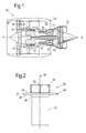
- a ducted fan gas turbine engine incorporating the invention is generally indicated at 10 and has a principal and rotational axis X-X.
- the engine comprises, in axial flow series, an air intake 11, a propulsive fan 12, an intermediate pressure compressor 13, a high-pressure compressor 14, combustion equipment 15, a high-pressure turbine 16, and intermediate pressure turbine 17, a low-pressure turbine 18 and a core engine exhaust nozzle 19.
- a nacelle generally surrounds the engine 10 and defines the intake 11, a bypass duct 22 and a bypass exhaust nozzle 23.
- air entering the intake 11 is accelerated by the fan 12 to produce two air flows: a first air flow A into the intermediate pressure compressor 13 and a second air flow B which passes through the bypass duct 22 to provide propulsive thrust.
- the intermediate pressure compressor 13 compresses the air flow A directed into it before delivering that air to the high pressure compressor 14 where further compression takes place.
- the compressed air exhausted from the high-pressure compressor 14 is directed into the combustion equipment 15 where it is mixed with fuel and the mixture combusted.
- the resultant hot combustion products then expand through, and thereby drive the high, intermediate and low-pressure turbines 16, 17, 18 before being exhausted through the nozzle 19 to provide additional propulsive thrust.
- the high, intermediate and low-pressure turbines respectively drive the high and intermediate pressure compressors 14, 13 and the fan 12 by suitable interconnecting shafts.
- the individual turbines 16, 17, 18 of the engine 10 are provided with service pipes (not shown in figure 1 ) which are connected through the respective turbine cases via service pipe assemblies which may be provided with respective flow deflectors in accordance with the present invention and which are described below in more detail.
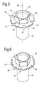
- FIG. 2 there is illustrated a long-reach nut 30 which forms part of a service pipe assembly to connect a service pipe through an aperture in a turbine case.
- the nut 30 is internally screw threaded in a conventional manner and has an elongate hollow shank 31, and a head 32.
- the head 32 is configured for engagement by an appropriate tool for tightening and loosening the nut in a generally conventional manner, and so preferably has a conventional hex configuration as illustrated.
- the hex head 32 thus defines a plurality of generally planar facets.
- the nut 30 also includes a generally circular flange 34 which extends outwardly from the shank 31, immediately below the level of the head 32 (in the orientation illustrated in figure 2 ).
- the flange 34 is generally planar in form and thus defines oppositely directed upper and lower annular and planar 35, 36 surfaces around the shank 31, both of which generally orthogonal to the longitudinal axis 38 of the nut.
- the flange also defines a peripheral edge 37 and has a diameter which is considerably greater than the diameter of both the shank 31 and the head 32.
- the flange 34 is provided between the shank 31 and the head 32, it does not interfere with the process of engaging an appropriate tool (such as a socket or a wrench) with the head 32 for the process of tightening or loosening the nut.
- the lower annular surface 36 of the flange 34 of the nut illustrated in figure 2 is generally planar, although its intersection 39 with the cylindrical outer surface of the shank 31 is chamfered in order to provide a smooth transition between the outer surface of the shank 31 and the lower surface 36 for flow deflecting purposes, as will be explained in more detail below.
- FIG 3 there is illustrated an alternative configuration of nut 30 which can be used in the flow-deflector of the present invention.
- the nut illustrated in figure 3 is identical to the one illustrated in figure 2 , and so the same reference numerals are used to denote identical or equivalent parts, which will not be described in further detail.
- the alternative configuration of nut 30 illustrated in figure 3 does not have a planar lower surface 36 as in the case of the nut illustrated in figure 2 .
- the nut shown in figure 3 has a lower surface 36 which is stepped, at 40.
- Figure 4 shows an alternative flange configuration which can be provided in either the planar configuration of figure 2 , or the stepped configuration of figure 3 .
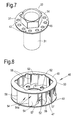
- this configuration of flange 34 has a generally circular profile, but is modified by the addition of a plurality of spaced-apart notches or recesses 41 formed around the peripheral edge 37, each of which is concave in form and extends inwardly from the otherwise circular peripheral edge.
- the flange 34 is provided with a plurality of small flow ports 43, each of which is located generally adjacent the peripheral edge of the flange and between a pair of the notches or recesses 41.
- the alternative flange 34 illustrated in figure 5 can be considered similar to the configuration illustrated in figure 4 in the sense that it also has a generally circular profile with a plurality of spaced-apart notches or recesses 41 formed around its peripheral edge 37.
- the notches or recesses 41 are not arcuate, but rather are square or rectangular in form.
- each notch or recess 41 is defined by a pair of opposed parallel side edges 44 which extend approximately (although not exactly on account of their parallel and spaced-art relationship) radially inwardly from the peripheral edge 37.
- each notch or recess 41 define respective planar surfaces which are parallel and inclined relative to the planes of the upper and lower flange surfaces 35, 36 such that they each make an equal acute angle to the planes of the upper and lower flange surfaces 35, 36.
- the notches or recesses 41 are thus configured to deflect any fluid flow passing through them from a generally axial direction along the shank 31 of the nut, such that the fluid flow becomes directed generally tangentially relative to the axis 38 of the nut, and at an acute upwards angle relative to the flange 34.
- Figure 6 illustrates another possible flange configuration, in which the flange 34 is again provided with a plurality of generally rectangular notches or recesses 41 around its peripheral edge 37.
- the flange 34 is again provided with a plurality of generally rectangular notches or recesses 41 around its peripheral edge 37.
- there are more notches or recesses 41 than in the arrangement of figure 5 such that the notches or recesses 41 are spaced more closely to one another.
- the parallel side edges 44 of each notch or recess 41 are somewhat shorter than those of the arrangement shown in figure 5 , and also are shown to define respective surfaces which are perpendicular to the upper and lower planar surfaces 35, 36 of the flange.
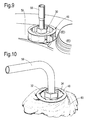
- Figure 7 shows another possible configuration of the flange 34, in which the flange is circular in form having an uninterrupted peripheral edge 37, but is instead provided with a plurality of relatively large flow ports 45 around its annular extent, in addition to the smaller flow ports 43.
- the flange 34 will preferably be formed integrally with the nut 30. However, it is also possible to provide the flange as a separate integer configured for secure attachment to the nut 30
- FIG 8 there is illustrated a generally annular shroud 46 which is provided as a separate component to the nut 30.
- shroud 46 and the flanged nut 30 are configured to cooperate in deflecting a leakage flow of fluid.
- the shroud comprises a pair of spaced apart annular plates, namely a mounting plate 47 and a top plate 48, both of which have circular peripheral edges 49, 50 of generally equal diameter.
- the mounting plate defines a central aperture 51 which is sized to receive therethrough the shank 31 of the nut 30, which it will be remembered will form part of a service pipe assembly when appropriately mounted to the turbine case of the engine.
- the central aperture 51 is preferably sized so as to be slightly larger than the outer diameter of the shank 31.
- Around the central aperture 51 there are provided a plurality of smaller spaced-apart mounting apertures 52.
- the top plate 48 also defines a central aperture 53, which is significantly larger in diameter than the central aperture of the mounting plate 47.
- the central aperture 53 is preferably slightly larger than the outer diameter of the flange 34 provided on the nut 30.
- the mounting plate 47 and the top plate 48 are interconnected and spaced apart by a plurality of circumferentially spaced apart vanes 54 which are arranged in partially overlapping relation to one another around the shroud.
- the vanes 54 are each aerofoil-shaped in cross-section and define respective leading edges 55 and trailing edges 56.
- the leading edges 55 of the vanes are all equi-spaced from the centre of the shroud, and the trailing edges 56 are all provided in alignment with the peripheral edges 49, 50 of the two plates 47, 48.
- the vanes 54 are arranged generally tangentially around the shroud so as to define curved and outwardly extending flow passage 57 between each adjacent pair.
- Each vane defines a pair of opposed deflector surfaces 54a extending between its leading and trailing edges.
- FIG. 9 the nut 30 and shroud 46 are shown in combination with a service pipe assembly 58 which is mounted through an aperture (not visible in figure 9 ) through the case 59 of a turbine within the core of a gas turbine engine, in order to define a flow deflector arrangement in accordance with the present invention.
- a service pipe assembly 58 which is mounted through an aperture (not visible in figure 9 ) through the case 59 of a turbine within the core of a gas turbine engine, in order to define a flow deflector arrangement in accordance with the present invention.
- the flange 34 of the nut shown in figure 9 is the simple circular configuration shown in figure 2 .
- the shroud 46 is first secured in position against the outside of the turbine case 59, such that the mounting plate 47 sits against the outer surface of the case 59, with its central aperture 51 aligned over the pipe-aperture formed in the case 59.
- the shroud is connected to the case 59 via bolts or other similar fasteners, through the mounting apertures 52.
- the service pipe assembly 58 is connected to the turbine case 59 in a generally conventional manner, such that the long-reach nut 30 passes through the centre of the annular shroud 46 as illustrated in figure 9 .
- the nut can be installed through the shroud 46 after the shroud has been mounted to the turbine case 59. Furthermore, it will be noted that because the flange 34 is provided beneath the hex head 32, the head 32 can easily be engaged by an appropriate tool in order to tighten the nut 30, even in the presence of the shroud 46.
- the deflected leakage flow will thus be directed between adjacent vanes 54 and thus through the curved flow passages 57 defined between the vanes 54.
- the curved configuration of the vanes 54, and their tangential configuration, imparts a degree of swirl to the leakage flow as it is directed outwardly through the flow passages 57.
- the flange 34 and the vanes 54 of the shroud thus cooperate to deflect the leakage flow of gas and impart swirl to it which facilitates improved mixing of the very hot leakage flow with cooler bulk air outside the turbine case 59, thereby preventing very hot gas from impinging on any vulnerable engine components in the area.
- Figure 10 is a Computational Fluid Dynamics representation of the deflected leakage flow 60, and clearly illustrates the swirl imparted to the flow, generally around the central axis of the nut and pipe assembly.
- any of the other previously described alternative flange configurations can be used with the shroud 47 in a generally similar manner, in which case the particular flow characteristics of the deflected flow will be slightly different.
- the presence of the notches or recesses 41, and/or flow apertures 43, 45 in the flange 34 will permit some of the deflected flow to pass through the flange and/or between the flange and the shroud, in additional to the major component of the deflected flow which will pass between the vanes of the shroud.
- shroud 46 is also suitable for use with the flow deflector arrangement of the present invention.
- an alternative shroud 46 is illustrated in figure 11 , the shroud being shown in combination with a flanged nut 30 having a flange 34 of the simple circular configuration shown in figures 2 , 9 and 10 .
- the shroud 46 shown in figure 11 has a mounting plate 47 of similar configuration to the shroud shown in figures 8 and 9 .
- this configuration of shroud has no top plate, or vanes 54 of the type described previously.
- the shroud 46 comprises a curved side wall 61 which extends upwardly from the edge of the mounting plate 47 and which extends around the major proportion of the pipe assembly and shank 31 of the nut 30.
- the side wall 61 terminates with an upper edge 62 which, when the shroud is mounted to the turbine case and the nut 30 is tightened to secure the pipe assembly (in the relative positions illustrated in figure 11 ), is spaced slightly further from the turbine case than the flange 34.
- a flow opening 63 is defined between the two end edges 64 of the side wall 61.
- the inner surface 65 of the sidewall 61 thus effectively defines a deflector surface which extends most, but not all of the way around the shank 31 of the nut and which cooperates with the flange 34 to deflect a leakage flow outwardly from the shank and with a degree of swirl.
- the swirl is imparted to the leakage flow due the circular profile of the inner deflector surface 65 of the side wall 61, and the leakage flow is directed outwardly through the flow opening 63 defined between the end edges 64 of the side wall.
- Figure 12 illustrates another configuration of shroud 46, which can be considered a modification of the arrangement illustrated in figure 11 .
- the sidewall 61 does not extend orthogonally relative to the mounting plate 47 of the shroud, but instead has a curved profile in cross-section, such that it extends radially outwardly and away from the mounting plate 47 before curving back towards the peripheral edge 37 of the flange 34.
- the shroud shown in figure 12 cooperates with the flange 34 in a similar manner to the arrangement shown in figure 11 and described above, but the curved cross-sectional profile of the sidewall 61 creates a larger space between its inner deflector surface 65, the shank 31 and the flange 34.
- FIG 13 illustrates another alternative configuration of shroud 46.
- the mounting plate 47 is generally polygonal, with a respective planar sidewall 61 extending away from each edge of the mounting plate 47, and generally towards the peripheral edge 37 of the flange 34.
- the sidewalls 61 each define a respective inner deflector surface 65, the deflector surfaces 65 all cooperating to encircle the shank 31 of the nut 30.
- one side edge of the mounting plate 47 is free of any sidewall 61, the gap between the two adjacent sidewalls defining a flow opening 63 similar to those of the shrouds illustrated in figures 11 and 12 .
Landscapes
- Engineering & Computer Science (AREA)
- Mechanical Engineering (AREA)
- General Engineering & Computer Science (AREA)
- Chemical & Material Sciences (AREA)
- Combustion & Propulsion (AREA)
- Physics & Mathematics (AREA)
- Fluid Mechanics (AREA)
- Turbine Rotor Nozzle Sealing (AREA)
Abstract
Description
- The present invention relates to a flow deflector arrangement. More particularly the invention relates to a flow deflector arrangement for use in combination with a pipe arrangement secured through a component. The invention finds particular application in a gas turbine engine, where the component is a turbine case.
- Within a gas turbine engine it is usual to provide a number of service pipes around the case of a turbine within the core part of the engine. The service pipes pass generally radially through respective apertures formed in the turbine case and are secured to the turbine case by respective service pipe assemblies on the outside of the case. The service pipe assemblies each usually comprise a long-reach threaded hex nut which is tightened to secure the service pipe and the assembly in position. As will be appreciated, the service pipes all need to be sealed against the apertures via which they extend through the turbine casing to prevent the leakage of hot gases from within the turbine.
- Given that the gas inside a turbine casing is extremely hot during operation of a gas turbine engine (typically approximately 790 Kelvin in the case of the high pressure turbine of an engine), leakage of the gas through the seals at service pipe positions around the turbine case, for example because of seal failure, is problematic because the high pressure of the gas within the turbine creates an outwardly directed jet of concentrated and very hot gas which can damage other engine components provided outside the turbine casing if it should impinge upon them. For example, in some gas turbine engine designs for the aeronautical industry, components of thrust reversing arrangements are often positioned outside the high pressure turbine, and these components can be damaged by exposure to hot gas leaking through service pipe connections.
- In order to address the above-described problems associated with leakage of hot gas through the service pipe connections to the turbine, it has been proposed previously to fit flow deflectors to the hex nuts of each service pipe assembly in order to deflect any leakage flow of gas flowing outwardly from the turbine and generally along the pipe arrangement, such that it will not impinge on any vulnerable components outside the turbine. Such flow-deflectors are typically fitted to the hex nuts after the nuts have been tightened to secure the service pipe assemblies, and their use thus complicates assembly and engine service procedures. Additionally, prior art flow deflectors of this type add considerable mass to the engine and to the sensitive interface between internal and external pipes at the turbine case. The mass of the flow deflectors can increase the contact loading of the seals around the service pipe assemblies which can increase the risk of the seals failing through wear. It is also possible for prior art flow deflectors fitted to the hex nuts to work lose over time which can cause damage to the service pipes or other components in the area.
- It is a preferred object of the present invention to provide an improved flow deflector arrangement.
- According to a first aspect of the present invention, there is provided a flow deflector arrangement for use in combination with a pipe arrangement secured through a component, the flow deflector arrangement comprising: a nut to secure the pipe arrangement to said component, and a shroud configured for attachment to said component so as to extend at least partially around the pipe arrangement when the pipe arrangement is secured to said component by the nut; wherein the nut has an outwardly directed flange configured to adopt a position spaced from said component, and the shroud defines at least one deflector surface which, when the shroud is attached to said component around the pipe arrangement, extends away from said component in spaced relation to the pipe arrangement; the flange and said at least one deflector surface thus being configured to cooperate in deflecting a flow of fluid flowing from said component and along the outside of the pipe arrangement such that the flow is deflected generally outwardly from the pipe arrangement with a degree of swirl.
- The flange may be formed integrally on the nut.
- The nut and the flange may be provided as separate parts.
- The flange may be circular. The shroud may be generally annular.
- The shroud may have a mounting plate for attachment to said component, the mounting plate defining an aperture configured to receive the pipe arrangement through the mounting plate.
- The shroud may be configured such that when the shroud is attached to said component the or each said deflector surface extends away from said component by a distance which is at least equal to the spacing between said flange and the component.
- The shroud may be configured for attachment to said component prior to the pipe arrangement, and wherein the shroud is configured to permit, thereafter, access to the nut for securing the pipe arrangement to said component.
- The flange may have a planar surface configured to lie in facing relation to a surface of said component when the pipe arrangement is secured to said component by the nut.
- Alternatively, the flange may have a stepped surface configured to lie in facing relation to a surface of said component when the pipe arrangement is secured to said component by the nut.
- The shroud may be annular in form so as extend to around the pipe arrangement and may have a plurality of vanes arranged in spaced relation to one another around the shroud, each vane defining at least one said deflector surface.
- Each said vane may be aerofoil-shaped.
- Alternatively, the shroud may define a single deflector surface which is configured to extend only partially around the pipe arrangement, in spaced relation to the pipe arrangement, when the shroud is attached to said component around the pipe arrangement.
- The nut may form part of the pipe arrangement.
- The flow deflector arrangement of the present invention may be provided on a gas turbine engine, wherein said component is a turbine case within the engine and said pipe arrangement is a service pipe assembly secured through the turbine case.
- According to another aspect of the present invention, there is provided a gas turbine engine having a turbine case and a service pipe assembly secured through the turbine case, the engine having a flow deflector arrangement of the type described above, wherein said shroud is attached to the outside of the turbine case, around the service pipe assembly, and the service pipe assembly is secured through the turbine case by said nut, the flow deflector arrangement being configured to deflect any leakage flow of gas flowing outwardly through the turbine case and along the outside of the service pipe assembly during operation of the engine such that the leakage flow becomes mixed with air outside the turbine case.
- So that the invention may be more readily understood, and so that further features thereof may be appreciated, embodiments of the invention will now be described by way of example with reference to the accompanying drawings in which:
-
Figure 1 shows schematically a longitudinal section through a gas turbine engine; -
Figure 2 is a schematic side elevational view showing a nut forming part of a flow deflector arrangement in accordance with an embodiment of the present invention; -
Figure 3 is a schematic side elevational view showing a nut of an alternative configuration which can also be used in the present invention; -
Figure 4 is a schematic perspective view from above, showing a nut of another configuration; -
Figure 5 is a schematic perspective view from above, showing a nut of a further configuration; -
Figure 6 is a schematic perspective view from above, showing a nut of yet another configuration; -
Figure 7 is a schematic perspective view from above, showing another configuration of nut; -
Figure 8 is a schematic perspective view showing a deflector shroud forming part of a flow deflector arrangement in accordance with an embodiment of the present invention; -
Figure 9 is a schematic perspective view showing a complete flow deflector arrangement in accordance with the present invention, installed in a gas turbine engine having a service pipe arrangement; -
Figure 10 is a schematic perspective view showing the flow deflecting effect of the flow deflector arrangement illustrated infigure 9 ; -
Figure 11 is a schematic perspective view showing a flow deflector arrangement incorporating an alternative configuration of deflector shroud; -
Figure 12 is a schematic perspective view showing a flow deflector arrangement incorporating another alternative configuration of deflector shroud; and -
Figure 13 is a schematic perspective view showing a flow deflector arrangement incorporating a further alternative configuration of deflector shroud. - With reference to
Figure 1 , a ducted fan gas turbine engine incorporating the invention is generally indicated at 10 and has a principal and rotational axis X-X. The engine comprises, in axial flow series, an air intake 11, apropulsive fan 12, anintermediate pressure compressor 13, a high-pressure compressor 14,combustion equipment 15, a high-pressure turbine 16, andintermediate pressure turbine 17, a low-pressure turbine 18 and a coreengine exhaust nozzle 19. A nacelle generally surrounds theengine 10 and defines the intake 11, abypass duct 22 and abypass exhaust nozzle 23. - During operation, air entering the intake 11 is accelerated by the
fan 12 to produce two air flows: a first air flow A into theintermediate pressure compressor 13 and a second air flow B which passes through thebypass duct 22 to provide propulsive thrust. Theintermediate pressure compressor 13 compresses the air flow A directed into it before delivering that air to thehigh pressure compressor 14 where further compression takes place. - The compressed air exhausted from the high-
pressure compressor 14 is directed into thecombustion equipment 15 where it is mixed with fuel and the mixture combusted. The resultant hot combustion products then expand through, and thereby drive the high, intermediate and low-pressure turbines nozzle 19 to provide additional propulsive thrust. The high, intermediate and low-pressure turbines respectively drive the high andintermediate pressure compressors fan 12 by suitable interconnecting shafts. - As is conventional, the
individual turbines engine 10 are provided with service pipes (not shown infigure 1 ) which are connected through the respective turbine cases via service pipe assemblies which may be provided with respective flow deflectors in accordance with the present invention and which are described below in more detail. - Turning now to consider
figure 2 , there is illustrated a long-reach nut 30 which forms part of a service pipe assembly to connect a service pipe through an aperture in a turbine case. Thenut 30 is internally screw threaded in a conventional manner and has an elongatehollow shank 31, and ahead 32. Thehead 32 is configured for engagement by an appropriate tool for tightening and loosening the nut in a generally conventional manner, and so preferably has a conventional hex configuration as illustrated. Thehex head 32 thus defines a plurality of generally planar facets. - The
nut 30 also includes a generallycircular flange 34 which extends outwardly from theshank 31, immediately below the level of the head 32 (in the orientation illustrated infigure 2 ). Theflange 34 is generally planar in form and thus defines oppositely directed upper and lower annular and planar 35, 36 surfaces around theshank 31, both of which generally orthogonal to thelongitudinal axis 38 of the nut. The flange also defines aperipheral edge 37 and has a diameter which is considerably greater than the diameter of both theshank 31 and thehead 32. As will be noted fromfigure 2 , because theflange 34 is provided between theshank 31 and thehead 32, it does not interfere with the process of engaging an appropriate tool (such as a socket or a wrench) with thehead 32 for the process of tightening or loosening the nut. - As indicated above, the lower
annular surface 36 of theflange 34 of the nut illustrated infigure 2 is generally planar, although itsintersection 39 with the cylindrical outer surface of theshank 31 is chamfered in order to provide a smooth transition between the outer surface of theshank 31 and thelower surface 36 for flow deflecting purposes, as will be explained in more detail below. - Turning now to consider
figure 3 , there is illustrated an alternative configuration ofnut 30 which can be used in the flow-deflector of the present invention. In many respects the nut illustrated infigure 3 is identical to the one illustrated infigure 2 , and so the same reference numerals are used to denote identical or equivalent parts, which will not be described in further detail. However, a notable difference is that the alternative configuration ofnut 30 illustrated infigure 3 does not have a planarlower surface 36 as in the case of the nut illustrated infigure 2 . Instead, the nut shown infigure 3 has alower surface 36 which is stepped, at 40. -
Figure 4 shows an alternative flange configuration which can be provided in either the planar configuration offigure 2 , or the stepped configuration offigure 3 . As will be noted, rather than being perfectly circular, this configuration offlange 34 has a generally circular profile, but is modified by the addition of a plurality of spaced-apart notches or recesses 41 formed around theperipheral edge 37, each of which is concave in form and extends inwardly from the otherwise circular peripheral edge. Additionally, theflange 34 is provided with a plurality ofsmall flow ports 43, each of which is located generally adjacent the peripheral edge of the flange and between a pair of the notches or recesses 41. - The
alternative flange 34 illustrated infigure 5 can be considered similar to the configuration illustrated infigure 4 in the sense that it also has a generally circular profile with a plurality of spaced-apart notches or recesses 41 formed around itsperipheral edge 37. However, in this embodiment the notches or recesses 41 are not arcuate, but rather are square or rectangular in form. Furthermore, each notch orrecess 41 is defined by a pair of opposed parallel side edges 44 which extend approximately (although not exactly on account of their parallel and spaced-art relationship) radially inwardly from theperipheral edge 37. The side edges 44 of each notch orrecess 41 define respective planar surfaces which are parallel and inclined relative to the planes of the upper and lower flange surfaces 35, 36 such that they each make an equal acute angle to the planes of the upper and lower flange surfaces 35, 36. The notches or recesses 41 are thus configured to deflect any fluid flow passing through them from a generally axial direction along theshank 31 of the nut, such that the fluid flow becomes directed generally tangentially relative to theaxis 38 of the nut, and at an acute upwards angle relative to theflange 34. -
Figure 6 illustrates another possible flange configuration, in which theflange 34 is again provided with a plurality of generally rectangular notches or recesses 41 around itsperipheral edge 37. However, it will be noted that in this arrangement, there are more notches or recesses 41 than in the arrangement offigure 5 , such that the notches or recesses 41 are spaced more closely to one another. Also it will be noted that in this arrangement the parallel side edges 44 of each notch orrecess 41 are somewhat shorter than those of the arrangement shown infigure 5 , and also are shown to define respective surfaces which are perpendicular to the upper and lowerplanar surfaces -
Figure 7 shows another possible configuration of theflange 34, in which the flange is circular in form having an uninterruptedperipheral edge 37, but is instead provided with a plurality of relativelylarge flow ports 45 around its annular extent, in addition to thesmaller flow ports 43. - It is to be noted that regardless of the actual profile of the
flange 34, theflange 34 will preferably be formed integrally with thenut 30. However, it is also possible to provide the flange as a separate integer configured for secure attachment to thenut 30 - Turning now to consider
figure 8 , there is illustrated a generallyannular shroud 46 which is provided as a separate component to thenut 30. As will be explained in more detail below, theshroud 46 and theflanged nut 30 are configured to cooperate in deflecting a leakage flow of fluid. - The shroud comprises a pair of spaced apart annular plates, namely a mounting
plate 47 and atop plate 48, both of which have circularperipheral edges central aperture 51 which is sized to receive therethrough theshank 31 of thenut 30, which it will be remembered will form part of a service pipe assembly when appropriately mounted to the turbine case of the engine. Thecentral aperture 51 is preferably sized so as to be slightly larger than the outer diameter of theshank 31. Around thecentral aperture 51, there are provided a plurality of smaller spaced-apart mountingapertures 52. - As shown in
figure 8 , thetop plate 48 also defines acentral aperture 53, which is significantly larger in diameter than the central aperture of the mountingplate 47. Thecentral aperture 53 is preferably slightly larger than the outer diameter of theflange 34 provided on thenut 30. - The mounting
plate 47 and thetop plate 48 are interconnected and spaced apart by a plurality of circumferentially spaced apart vanes 54 which are arranged in partially overlapping relation to one another around the shroud. Thevanes 54 are each aerofoil-shaped in cross-section and define respectiveleading edges 55 and trailingedges 56. In the particular arrangement illustrated, the leadingedges 55 of the vanes are all equi-spaced from the centre of the shroud, and the trailingedges 56 are all provided in alignment with theperipheral edges plates vanes 54 are arranged generally tangentially around the shroud so as to define curved and outwardly extendingflow passage 57 between each adjacent pair. Each vane defines a pair of opposeddeflector surfaces 54a extending between its leading and trailing edges. - Turning now to consider
figure 9 , thenut 30 andshroud 46 are shown in combination with aservice pipe assembly 58 which is mounted through an aperture (not visible infigure 9 ) through thecase 59 of a turbine within the core of a gas turbine engine, in order to define a flow deflector arrangement in accordance with the present invention. It will be noted that theflange 34 of the nut shown infigure 9 is the simple circular configuration shown infigure 2 . - In order to assemble the flow deflector arrangement, the
shroud 46 is first secured in position against the outside of theturbine case 59, such that the mountingplate 47 sits against the outer surface of thecase 59, with itscentral aperture 51 aligned over the pipe-aperture formed in thecase 59. The shroud is connected to thecase 59 via bolts or other similar fasteners, through the mountingapertures 52. Thereafter, theservice pipe assembly 58 is connected to theturbine case 59 in a generally conventional manner, such that the long-reach nut 30 passes through the centre of theannular shroud 46 as illustrated infigure 9 . As will be noted, because thecentral aperture 53 formed in thetop plate 48 of the shroud is larger in diameter than theflange 34 of thenut 30, the nut can be installed through theshroud 46 after the shroud has been mounted to theturbine case 59. Furthermore, it will be noted that because theflange 34 is provided beneath thehex head 32, thehead 32 can easily be engaged by an appropriate tool in order to tighten thenut 30, even in the presence of theshroud 46. - As also illustrated in
figure 9 , when thenut 30 is installed to secure theservice pipe assembly 58, itsflange 34 adopts a position in which it is spaced from theturbine case 59, such that thelower surface 36 of the flange lies in facing relation to the outer surface of the turbine case, with the mountingplate 47 of theshroud 46 therebetween. Theflange 34 of the nut also adopts a position in which it lies beneath the level of thetop plate 48 of theshroud 46, such that thevanes 54 all extend away from the turbine case, in radially-spaced relation to the pipe assembly and theshank 31 of the nut, and slightly past theflange 34. - In the event of failure of the seal provided between the
pipe assembly 58 and theturbine case 59, a leakage flow of very hot gas will be produced which will be directed generally along the outside of theshank 31 of thenut 30, which of course effectively forms part of the service pipe assembly. Any such leakage flow will thus be directed outwardly from the turbine case and into the annular space defined between theshank 31, theflange 34, and thevanes 54 of theshroud 46. Components of the leakage flow directed generally along theshank 31 will thus impinge against thelower surface 36 of theflange 34 and will thereby be deflected so as to be redirected generally radially outwardly away from the shank and the pipe assembly and towards thevanes 54 and theirrespective deflector surfaces 54a. The deflected leakage flow will thus be directed betweenadjacent vanes 54 and thus through thecurved flow passages 57 defined between thevanes 54. The curved configuration of thevanes 54, and their tangential configuration, imparts a degree of swirl to the leakage flow as it is directed outwardly through theflow passages 57. Theflange 34 and thevanes 54 of the shroud thus cooperate to deflect the leakage flow of gas and impart swirl to it which facilitates improved mixing of the very hot leakage flow with cooler bulk air outside theturbine case 59, thereby preventing very hot gas from impinging on any vulnerable engine components in the area. -
Figure 10 is a Computational Fluid Dynamics representation of the deflectedleakage flow 60, and clearly illustrates the swirl imparted to the flow, generally around the central axis of the nut and pipe assembly. - It is to be noted that any of the other previously described alternative flange configurations can be used with the
shroud 47 in a generally similar manner, in which case the particular flow characteristics of the deflected flow will be slightly different. For example, the presence of the notches or recesses 41, and/or flowapertures flange 34 will permit some of the deflected flow to pass through the flange and/or between the flange and the shroud, in additional to the major component of the deflected flow which will pass between the vanes of the shroud. - It is to be appreciated that other configurations of the
shroud 46 are also suitable for use with the flow deflector arrangement of the present invention. For example, analternative shroud 46 is illustrated infigure 11 , the shroud being shown in combination with aflanged nut 30 having aflange 34 of the simple circular configuration shown infigures 2 ,9 and 10 . - The
shroud 46 shown infigure 11 has a mountingplate 47 of similar configuration to the shroud shown infigures 8 and9 . However, this configuration of shroud has no top plate, orvanes 54 of the type described previously. Instead, theshroud 46 comprises acurved side wall 61 which extends upwardly from the edge of the mountingplate 47 and which extends around the major proportion of the pipe assembly andshank 31 of thenut 30. Theside wall 61 terminates with anupper edge 62 which, when the shroud is mounted to the turbine case and thenut 30 is tightened to secure the pipe assembly (in the relative positions illustrated infigure 11 ), is spaced slightly further from the turbine case than theflange 34. - As illustrated, because the
side wall 61 extends only partially around thenut 30 when installed in the relative positions illustrated, a flow opening 63 is defined between the twoend edges 64 of theside wall 61. - The
inner surface 65 of thesidewall 61 thus effectively defines a deflector surface which extends most, but not all of the way around theshank 31 of the nut and which cooperates with theflange 34 to deflect a leakage flow outwardly from the shank and with a degree of swirl. In this arrangement, the swirl is imparted to the leakage flow due the circular profile of theinner deflector surface 65 of theside wall 61, and the leakage flow is directed outwardly through the flow opening 63 defined between the end edges 64 of the side wall. -
Figure 12 illustrates another configuration ofshroud 46, which can be considered a modification of the arrangement illustrated infigure 11 . In this arrangement, thesidewall 61 does not extend orthogonally relative to the mountingplate 47 of the shroud, but instead has a curved profile in cross-section, such that it extends radially outwardly and away from the mountingplate 47 before curving back towards theperipheral edge 37 of theflange 34. The shroud shown infigure 12 cooperates with theflange 34 in a similar manner to the arrangement shown infigure 11 and described above, but the curved cross-sectional profile of thesidewall 61 creates a larger space between itsinner deflector surface 65, theshank 31 and theflange 34. -
Figure 13 illustrates another alternative configuration ofshroud 46. In this arrangement, the mountingplate 47 is generally polygonal, with a respectiveplanar sidewall 61 extending away from each edge of the mountingplate 47, and generally towards theperipheral edge 37 of theflange 34. Thesidewalls 61 each define a respectiveinner deflector surface 65, the deflector surfaces 65 all cooperating to encircle theshank 31 of thenut 30. As will be noted, one side edge of the mountingplate 47 is free of anysidewall 61, the gap between the two adjacent sidewalls defining a flow opening 63 similar to those of the shrouds illustrated infigures 11 and 12 . - When used in this specification and claims, the terms "comprises" and "comprising" and variations thereof mean that the specified features, steps or integers are included. The terms are not to be interpreted to exclude the presence of other features, steps or integers.
- The features disclosed in the foregoing description, or in the following claims, or in the accompanying drawings, expressed in their specific forms or in terms of a means for performing the disclosed function, or a method or process for obtaining the disclosed results, as appropriate, may, separately, or in any combination of such features, be utilised for realising the invention in diverse forms thereof.
- While the invention has been described in conjunction with the exemplary embodiments described above, many equivalent modifications and variations will be apparent to those skilled in the art when given this disclosure. Accordingly, the exemplary embodiments of the invention set forth above are considered to be illustrative and not limiting. Various changes to the described embodiments may be made without departing from the spirit and scope of the invention.
Claims (15)
- A flow deflector arrangement for use in combination with a pipe arrangement (58) secured through a component (59), the flow deflector arrangement comprising: a nut (30) to secure the pipe arrangement (58) to said component (59), and a shroud (46) configured for attachment to said component (59) so as to extend at least partially around the pipe arrangement (58) when the pipe arrangement is secured to said component (59) by the nut (30); wherein the nut (30) has an outwardly directed flange (34) configured to adopt a position spaced from said component (59), and the shroud (46) defines at least one deflector surface (54a, 65) which, when the shroud is attached to said component (59) around the pipe arrangement, extends away from said component (59) in spaced relation to the pipe arrangement; the flange (34) and said at least one deflector surface (54a, 65) thus being configured to cooperate in deflecting a flow of fluid flowing from said component (59) and along the outside of the pipe arrangement (58) such that the flow is deflected generally outwardly from the pipe arrangement (58) with a degree of swirl (60).
- A flow deflector arrangement according to claim 1, wherein the flange (34) is formed integrally on the nut (30).
- A flow deflector arrangement according to claim 1 or claim 2, wherein the nut (30) and the flange (34) are provided as separate parts.
- A flow deflector arrangement according to any preceding claim, wherein the flange (34) is circular, and the shroud (46) is generally annular.
- A flow deflector arrangement according to any preceding claim, wherein the shroud (46) has a mounting plate (47) for attachment to said component, the mounting plate (47) defining an aperture (51) configured to receive the pipe arrangement through the mounting plate.
- A flow deflector arrangement according to any preceding claim, wherein the shroud (46) is configured such that when the shroud (46) is attached to said component (59) the or each said deflector surface (54a, 65) extends away from said component (59) by a distance which is at least equal to the spacing between said flange (34) and the component (59).
- A flow deflector arrangement according to any preceding claim, wherein the shroud (46) is configured for attachment to said component (59) prior to the pipe arrangement (58), and wherein the shroud (46) is configured to permit, thereafter, access to the nut (30) for securing the pipe arrangement (58) to said component (59).
- A flow deflector arrangement according to any preceding claim, wherein the flange (34) has a planar surface (36) configured to lie in facing relation to a surface of said component (59) when the pipe arrangement is secured to said component by the nut.
- A flow deflector arrangement according to any one of claims 1 to 7, wherein the flange (34) has a stepped surface (40) configured to lie in facing relation to a surface of said component (59) when the pipe arrangement is secured to said component by the nut.
- A flow deflector arrangement according to any preceding claim, wherein the shroud (46) is annular in form so as extend to around the pipe arrangement (58) and has a plurality of vanes (54) arranged in spaced relation to one another around the shroud (46), each vane (54) defining at least one said deflector surface (54a).
- A flow deflector arrangement according to claim 10, wherein each said vane (54) is aerofoil-shaped.
- A flow deflector arrangement according to any one of claims 1 to 9, wherein the shroud (46) defines a single deflector surface (65) which is configured to extend only partially around the pipe arrangement (58), in spaced relation to the pipe arrangement, when the shroud is attached to said component around the pipe arrangement.
- A flow deflector arrangement according to any preceding claim, wherein the nut (30) forms part of the pipe arrangement (58).
- A flow deflector arrangement according to any preceding claim, provided on a gas turbine engine (10), wherein said component is a turbine case (59) within the engine and said pipe arrangement (58) is a service pipe assembly secured through the turbine case (59).
- A gas turbine engine (10) having a turbine case (59) and a service pipe assembly (58) secured through the turbine case, the engine having a flow deflector arrangement according to any preceding claim, wherein said shroud (46) is attached to the outside of the turbine case (59), around the service pipe assembly (58), and the service pipe assembly is secured through the turbine case (59) by said nut (30), the flow deflector arrangement being configured to deflect any leakage flow of gas flowing outwardly through the turbine case (59) and along the outside of the service pipe assembly (58) during operation of the engine such that the leakage flow becomes mixed with air outside the turbine case (59).
Applications Claiming Priority (1)
| Application Number | Priority Date | Filing Date | Title |
|---|---|---|---|
| GBGB1315449.7A GB201315449D0 (en) | 2013-08-30 | 2013-08-30 | A flow detector arrangement |
Publications (3)
| Publication Number | Publication Date |
|---|---|
| EP2846048A2 true EP2846048A2 (en) | 2015-03-11 |
| EP2846048A3 EP2846048A3 (en) | 2015-05-06 |
| EP2846048B1 EP2846048B1 (en) | 2018-04-18 |
Family
ID=49397043
Family Applications (1)
| Application Number | Title | Priority Date | Filing Date |
|---|---|---|---|
| EP14180983.0A Not-in-force EP2846048B1 (en) | 2013-08-30 | 2014-08-14 | A flow deflector arrangement |
Country Status (3)
| Country | Link |
|---|---|
| US (1) | US9726030B2 (en) |
| EP (1) | EP2846048B1 (en) |
| GB (1) | GB201315449D0 (en) |
Cited By (1)
| Publication number | Priority date | Publication date | Assignee | Title |
|---|---|---|---|---|
| EP3561235A1 (en) * | 2018-04-27 | 2019-10-30 | MTU Aero Engines GmbH | Deflector nut for service pipe assemblies of turbine center frames |
Families Citing this family (1)
| Publication number | Priority date | Publication date | Assignee | Title |
|---|---|---|---|---|
| JP6194548B2 (en) * | 2014-09-29 | 2017-09-13 | ヨアウァパンクル,ルクスナラ | Device for generating a swirling flow of fluid |
Family Cites Families (11)
| Publication number | Priority date | Publication date | Assignee | Title |
|---|---|---|---|---|
| US5259725A (en) | 1992-10-19 | 1993-11-09 | General Electric Company | Gas turbine engine and method of assembling same |
| US6419446B1 (en) | 1999-08-05 | 2002-07-16 | United Technologies Corporation | Apparatus and method for inhibiting radial transfer of core gas flow within a core gas flow path of a gas turbine engine |
| US6339924B1 (en) * | 1999-12-20 | 2002-01-22 | General Electric Company | Method and apparatus for encapsulating gas turbine engine fuel connections |
| FR2875854B1 (en) | 2004-09-29 | 2009-04-24 | Snecma Propulsion Solide Sa | MIXER FOR TUYERE WITH SEPARATE FLUX |
| US7458618B2 (en) * | 2005-01-18 | 2008-12-02 | Fm Global Technologies | Fixed flange spray deflector |
| FR2935429B1 (en) * | 2008-08-26 | 2011-11-25 | Snecma | FIXED BLADE OF TURBOMACHINE WITH REDUCED MASS AND TURBOMACHINE COMPRISING AT LEAST ONE SUCH FIXED AUBAGE |
| US8091371B2 (en) * | 2008-11-28 | 2012-01-10 | Pratt & Whitney Canada Corp. | Mid turbine frame for gas turbine engine |
| GB0911667D0 (en) | 2009-07-06 | 2009-08-12 | Aesir Ltd | Improvements to controlling spin of an aircraft |
| GB201013093D0 (en) | 2010-08-04 | 2010-09-15 | Rolls Royce Plc | Ventilation inlet |
| US20140003920A1 (en) * | 2012-07-02 | 2014-01-02 | United Technologies Corporation | Flow metering anti-rotation outer diameter (od) hex nut |
| US8863531B2 (en) * | 2012-07-02 | 2014-10-21 | United Technologies Corporation | Cooling apparatus for a mid-turbine frame |
-
2013
- 2013-08-30 GB GBGB1315449.7A patent/GB201315449D0/en not_active Ceased
-
2014
- 2014-08-14 EP EP14180983.0A patent/EP2846048B1/en not_active Not-in-force
- 2014-08-14 US US14/459,820 patent/US9726030B2/en not_active Expired - Fee Related
Cited By (1)
| Publication number | Priority date | Publication date | Assignee | Title |
|---|---|---|---|---|
| EP3561235A1 (en) * | 2018-04-27 | 2019-10-30 | MTU Aero Engines GmbH | Deflector nut for service pipe assemblies of turbine center frames |
Also Published As
| Publication number | Publication date |
|---|---|
| US20150300188A1 (en) | 2015-10-22 |
| EP2846048A3 (en) | 2015-05-06 |
| GB201315449D0 (en) | 2013-10-16 |
| US9726030B2 (en) | 2017-08-08 |
| EP2846048B1 (en) | 2018-04-18 |
Similar Documents
| Publication | Publication Date | Title |
|---|---|---|
| US8579538B2 (en) | Turbine engine coupling stack | |
| US9341071B2 (en) | Locking spacer assembly | |
| US10233775B2 (en) | Engine component for a gas turbine engine | |
| JP2006002773A (en) | Assembly having gas turbine combustion chamber formed integrally with high-pressure turbine nozzle | |
| US8408868B2 (en) | Methods, systems and/or apparatus relating to inducers for turbine engines | |
| US7101150B2 (en) | Fastened vane assembly | |
| US11773748B2 (en) | High temperature flange joint, exhaust diffuser and method for coupling two components in a gas turbine engine | |
| US11448236B2 (en) | Outlet guide vane | |
| US7857585B2 (en) | Gas turbine engine comprising a casing surrounding a rotary assembly and a manifold secured to the casing via a securing arrangement | |
| US20090208325A1 (en) | Large fillet airfoil with fanned cooling hole array | |
| US20180274370A1 (en) | Engine component for a gas turbine engine | |
| EP2846048B1 (en) | A flow deflector arrangement | |
| US8539774B2 (en) | Fuel injector mounting system | |
| US20170167381A1 (en) | Turbulators for improved cooling of gas turbine engine components | |
| US20170268357A1 (en) | Vane retainer | |
| EP2378082B1 (en) | Compressor assembly with a splitter | |
| GB2355301A (en) | A wall structure for a combustor of a gas turbine engine | |
| US20170211422A1 (en) | Turbomachine with an insert device that can be arranged inside a recess of a wall | |
| US20140033733A1 (en) | Flow discharge device | |
| US20190353054A1 (en) | Exhaust system for a gas turbine engine | |
| KR101781299B1 (en) | Blade for a turbine with dovetail | |
| JP7571117B2 (en) | Axial retention assembly for a combustor component of a gas turbine engine - Patents.com | |
| US11629599B2 (en) | Turbomachine nozzle with an airfoil having a curvilinear trailing edge | |
| US10753277B2 (en) | Inlet cap of an engine |
Legal Events
| Date | Code | Title | Description |
|---|---|---|---|
| 17P | Request for examination filed |
Effective date: 20140814 |
|
| AK | Designated contracting states |
Kind code of ref document: A2 Designated state(s): AL AT BE BG CH CY CZ DE DK EE ES FI FR GB GR HR HU IE IS IT LI LT LU LV MC MK MT NL NO PL PT RO RS SE SI SK SM TR |
|
| AX | Request for extension of the european patent |
Extension state: BA ME |
|
| PUAI | Public reference made under article 153(3) epc to a published international application that has entered the european phase |
Free format text: ORIGINAL CODE: 0009012 |
|
| PUAL | Search report despatched |
Free format text: ORIGINAL CODE: 0009013 |
|
| AK | Designated contracting states |
Kind code of ref document: A3 Designated state(s): AL AT BE BG CH CY CZ DE DK EE ES FI FR GB GR HR HU IE IS IT LI LT LU LV MC MK MT NL NO PL PT RO RS SE SI SK SM TR |
|
| AX | Request for extension of the european patent |
Extension state: BA ME |
|
| RIC1 | Information provided on ipc code assigned before grant |
Ipc: F15D 1/10 20060101AFI20150331BHEP Ipc: F02K 1/80 20060101ALI20150331BHEP Ipc: F15D 1/00 20060101ALI20150331BHEP |
|
| RAP1 | Party data changed (applicant data changed or rights of an application transferred) |
Owner name: ROLLS-ROYCE PLC |
|
| R17P | Request for examination filed (corrected) |
Effective date: 20151020 |
|
| RBV | Designated contracting states (corrected) |
Designated state(s): AL AT BE BG CH CY CZ DE DK EE ES FI FR GB GR HR HU IE IS IT LI LT LU LV MC MK MT NL NO PL PT RO RS SE SI SK SM TR |
|
| GRAP | Despatch of communication of intention to grant a patent |
Free format text: ORIGINAL CODE: EPIDOSNIGR1 |
|
| STAA | Information on the status of an ep patent application or granted ep patent |
Free format text: STATUS: GRANT OF PATENT IS INTENDED |
|
| INTG | Intention to grant announced |
Effective date: 20171222 |
|
| GRAS | Grant fee paid |
Free format text: ORIGINAL CODE: EPIDOSNIGR3 |
|
| GRAA | (expected) grant |
Free format text: ORIGINAL CODE: 0009210 |
|
| STAA | Information on the status of an ep patent application or granted ep patent |
Free format text: STATUS: THE PATENT HAS BEEN GRANTED |
|
| AK | Designated contracting states |
Kind code of ref document: B1 Designated state(s): AL AT BE BG CH CY CZ DE DK EE ES FI FR GB GR HR HU IE IS IT LI LT LU LV MC MK MT NL NO PL PT RO RS SE SI SK SM TR |
|
| REG | Reference to a national code |
Ref country code: GB Ref legal event code: FG4D |
|
| REG | Reference to a national code |
Ref country code: CH Ref legal event code: EP |
|
| REG | Reference to a national code |
Ref country code: AT Ref legal event code: REF Ref document number: 990810 Country of ref document: AT Kind code of ref document: T Effective date: 20180515 |
|
| REG | Reference to a national code |
Ref country code: IE Ref legal event code: FG4D |
|
| REG | Reference to a national code |
Ref country code: DE Ref legal event code: R096 Ref document number: 602014024009 Country of ref document: DE |
|
| REG | Reference to a national code |
Ref country code: NL Ref legal event code: MP Effective date: 20180418 |
|
| REG | Reference to a national code |
Ref country code: FR Ref legal event code: PLFP Year of fee payment: 5 |
|
| REG | Reference to a national code |
Ref country code: LT Ref legal event code: MG4D |
|
| PG25 | Lapsed in a contracting state [announced via postgrant information from national office to epo] |
Ref country code: NL Free format text: LAPSE BECAUSE OF FAILURE TO SUBMIT A TRANSLATION OF THE DESCRIPTION OR TO PAY THE FEE WITHIN THE PRESCRIBED TIME-LIMIT Effective date: 20180418 |
|
| PG25 | Lapsed in a contracting state [announced via postgrant information from national office to epo] |
Ref country code: SE Free format text: LAPSE BECAUSE OF FAILURE TO SUBMIT A TRANSLATION OF THE DESCRIPTION OR TO PAY THE FEE WITHIN THE PRESCRIBED TIME-LIMIT Effective date: 20180418 Ref country code: ES Free format text: LAPSE BECAUSE OF FAILURE TO SUBMIT A TRANSLATION OF THE DESCRIPTION OR TO PAY THE FEE WITHIN THE PRESCRIBED TIME-LIMIT Effective date: 20180418 Ref country code: LT Free format text: LAPSE BECAUSE OF FAILURE TO SUBMIT A TRANSLATION OF THE DESCRIPTION OR TO PAY THE FEE WITHIN THE PRESCRIBED TIME-LIMIT Effective date: 20180418 Ref country code: PL Free format text: LAPSE BECAUSE OF FAILURE TO SUBMIT A TRANSLATION OF THE DESCRIPTION OR TO PAY THE FEE WITHIN THE PRESCRIBED TIME-LIMIT Effective date: 20180418 Ref country code: AL Free format text: LAPSE BECAUSE OF FAILURE TO SUBMIT A TRANSLATION OF THE DESCRIPTION OR TO PAY THE FEE WITHIN THE PRESCRIBED TIME-LIMIT Effective date: 20180418 Ref country code: NO Free format text: LAPSE BECAUSE OF FAILURE TO SUBMIT A TRANSLATION OF THE DESCRIPTION OR TO PAY THE FEE WITHIN THE PRESCRIBED TIME-LIMIT Effective date: 20180718 Ref country code: BG Free format text: LAPSE BECAUSE OF FAILURE TO SUBMIT A TRANSLATION OF THE DESCRIPTION OR TO PAY THE FEE WITHIN THE PRESCRIBED TIME-LIMIT Effective date: 20180718 Ref country code: FI Free format text: LAPSE BECAUSE OF FAILURE TO SUBMIT A TRANSLATION OF THE DESCRIPTION OR TO PAY THE FEE WITHIN THE PRESCRIBED TIME-LIMIT Effective date: 20180418 |
|
| PG25 | Lapsed in a contracting state [announced via postgrant information from national office to epo] |
Ref country code: RS Free format text: LAPSE BECAUSE OF FAILURE TO SUBMIT A TRANSLATION OF THE DESCRIPTION OR TO PAY THE FEE WITHIN THE PRESCRIBED TIME-LIMIT Effective date: 20180418 Ref country code: HR Free format text: LAPSE BECAUSE OF FAILURE TO SUBMIT A TRANSLATION OF THE DESCRIPTION OR TO PAY THE FEE WITHIN THE PRESCRIBED TIME-LIMIT Effective date: 20180418 Ref country code: GR Free format text: LAPSE BECAUSE OF FAILURE TO SUBMIT A TRANSLATION OF THE DESCRIPTION OR TO PAY THE FEE WITHIN THE PRESCRIBED TIME-LIMIT Effective date: 20180719 Ref country code: LV Free format text: LAPSE BECAUSE OF FAILURE TO SUBMIT A TRANSLATION OF THE DESCRIPTION OR TO PAY THE FEE WITHIN THE PRESCRIBED TIME-LIMIT Effective date: 20180418 |
|
| REG | Reference to a national code |
Ref country code: AT Ref legal event code: MK05 Ref document number: 990810 Country of ref document: AT Kind code of ref document: T Effective date: 20180418 |
|
| PG25 | Lapsed in a contracting state [announced via postgrant information from national office to epo] |
Ref country code: PT Free format text: LAPSE BECAUSE OF FAILURE TO SUBMIT A TRANSLATION OF THE DESCRIPTION OR TO PAY THE FEE WITHIN THE PRESCRIBED TIME-LIMIT Effective date: 20180820 |
|
| REG | Reference to a national code |
Ref country code: DE Ref legal event code: R097 Ref document number: 602014024009 Country of ref document: DE |
|
| PG25 | Lapsed in a contracting state [announced via postgrant information from national office to epo] |
Ref country code: AT Free format text: LAPSE BECAUSE OF FAILURE TO SUBMIT A TRANSLATION OF THE DESCRIPTION OR TO PAY THE FEE WITHIN THE PRESCRIBED TIME-LIMIT Effective date: 20180418 Ref country code: DK Free format text: LAPSE BECAUSE OF FAILURE TO SUBMIT A TRANSLATION OF THE DESCRIPTION OR TO PAY THE FEE WITHIN THE PRESCRIBED TIME-LIMIT Effective date: 20180418 Ref country code: EE Free format text: LAPSE BECAUSE OF FAILURE TO SUBMIT A TRANSLATION OF THE DESCRIPTION OR TO PAY THE FEE WITHIN THE PRESCRIBED TIME-LIMIT Effective date: 20180418 Ref country code: SK Free format text: LAPSE BECAUSE OF FAILURE TO SUBMIT A TRANSLATION OF THE DESCRIPTION OR TO PAY THE FEE WITHIN THE PRESCRIBED TIME-LIMIT Effective date: 20180418 Ref country code: RO Free format text: LAPSE BECAUSE OF FAILURE TO SUBMIT A TRANSLATION OF THE DESCRIPTION OR TO PAY THE FEE WITHIN THE PRESCRIBED TIME-LIMIT Effective date: 20180418 Ref country code: CZ Free format text: LAPSE BECAUSE OF FAILURE TO SUBMIT A TRANSLATION OF THE DESCRIPTION OR TO PAY THE FEE WITHIN THE PRESCRIBED TIME-LIMIT Effective date: 20180418 |
|
| PLBE | No opposition filed within time limit |
Free format text: ORIGINAL CODE: 0009261 |
|
| STAA | Information on the status of an ep patent application or granted ep patent |
Free format text: STATUS: NO OPPOSITION FILED WITHIN TIME LIMIT |
|
| PG25 | Lapsed in a contracting state [announced via postgrant information from national office to epo] |
Ref country code: IT Free format text: LAPSE BECAUSE OF FAILURE TO SUBMIT A TRANSLATION OF THE DESCRIPTION OR TO PAY THE FEE WITHIN THE PRESCRIBED TIME-LIMIT Effective date: 20180418 Ref country code: SM Free format text: LAPSE BECAUSE OF FAILURE TO SUBMIT A TRANSLATION OF THE DESCRIPTION OR TO PAY THE FEE WITHIN THE PRESCRIBED TIME-LIMIT Effective date: 20180418 |
|
| 26N | No opposition filed |
Effective date: 20190121 |
|
| PG25 | Lapsed in a contracting state [announced via postgrant information from national office to epo] |
Ref country code: MC Free format text: LAPSE BECAUSE OF FAILURE TO SUBMIT A TRANSLATION OF THE DESCRIPTION OR TO PAY THE FEE WITHIN THE PRESCRIBED TIME-LIMIT Effective date: 20180418 |
|
| REG | Reference to a national code |
Ref country code: CH Ref legal event code: PL |
|
| PG25 | Lapsed in a contracting state [announced via postgrant information from national office to epo] |
Ref country code: LU Free format text: LAPSE BECAUSE OF NON-PAYMENT OF DUE FEES Effective date: 20180814 Ref country code: LI Free format text: LAPSE BECAUSE OF NON-PAYMENT OF DUE FEES Effective date: 20180831 Ref country code: CH Free format text: LAPSE BECAUSE OF NON-PAYMENT OF DUE FEES Effective date: 20180831 |
|
| REG | Reference to a national code |
Ref country code: BE Ref legal event code: MM Effective date: 20180831 |
|
| REG | Reference to a national code |
Ref country code: IE Ref legal event code: MM4A |
|
| PG25 | Lapsed in a contracting state [announced via postgrant information from national office to epo] |
Ref country code: SI Free format text: LAPSE BECAUSE OF FAILURE TO SUBMIT A TRANSLATION OF THE DESCRIPTION OR TO PAY THE FEE WITHIN THE PRESCRIBED TIME-LIMIT Effective date: 20180418 |
|
| PG25 | Lapsed in a contracting state [announced via postgrant information from national office to epo] |
Ref country code: IE Free format text: LAPSE BECAUSE OF NON-PAYMENT OF DUE FEES Effective date: 20180814 |
|
| PG25 | Lapsed in a contracting state [announced via postgrant information from national office to epo] |
Ref country code: BE Free format text: LAPSE BECAUSE OF NON-PAYMENT OF DUE FEES Effective date: 20180831 |
|
| PG25 | Lapsed in a contracting state [announced via postgrant information from national office to epo] |
Ref country code: MT Free format text: LAPSE BECAUSE OF NON-PAYMENT OF DUE FEES Effective date: 20180814 |
|
| PG25 | Lapsed in a contracting state [announced via postgrant information from national office to epo] |
Ref country code: TR Free format text: LAPSE BECAUSE OF FAILURE TO SUBMIT A TRANSLATION OF THE DESCRIPTION OR TO PAY THE FEE WITHIN THE PRESCRIBED TIME-LIMIT Effective date: 20180418 |
|
| PG25 | Lapsed in a contracting state [announced via postgrant information from national office to epo] |
Ref country code: HU Free format text: LAPSE BECAUSE OF FAILURE TO SUBMIT A TRANSLATION OF THE DESCRIPTION OR TO PAY THE FEE WITHIN THE PRESCRIBED TIME-LIMIT; INVALID AB INITIO Effective date: 20140814 |
|
| PG25 | Lapsed in a contracting state [announced via postgrant information from national office to epo] |
Ref country code: MK Free format text: LAPSE BECAUSE OF NON-PAYMENT OF DUE FEES Effective date: 20180418 Ref country code: CY Free format text: LAPSE BECAUSE OF FAILURE TO SUBMIT A TRANSLATION OF THE DESCRIPTION OR TO PAY THE FEE WITHIN THE PRESCRIBED TIME-LIMIT Effective date: 20180418 |
|
| PG25 | Lapsed in a contracting state [announced via postgrant information from national office to epo] |
Ref country code: IS Free format text: LAPSE BECAUSE OF FAILURE TO SUBMIT A TRANSLATION OF THE DESCRIPTION OR TO PAY THE FEE WITHIN THE PRESCRIBED TIME-LIMIT Effective date: 20180818 |
|
| PGFP | Annual fee paid to national office [announced via postgrant information from national office to epo] |
Ref country code: DE Payment date: 20201029 Year of fee payment: 7 |
|
| REG | Reference to a national code |
Ref country code: DE Ref legal event code: R119 Ref document number: 602014024009 Country of ref document: DE |
|
| PG25 | Lapsed in a contracting state [announced via postgrant information from national office to epo] |
Ref country code: DE Free format text: LAPSE BECAUSE OF NON-PAYMENT OF DUE FEES Effective date: 20220301 |
|
| PGFP | Annual fee paid to national office [announced via postgrant information from national office to epo] |
Ref country code: GB Payment date: 20220823 Year of fee payment: 9 |
|
| PGFP | Annual fee paid to national office [announced via postgrant information from national office to epo] |
Ref country code: FR Payment date: 20220824 Year of fee payment: 9 |
|
| P01 | Opt-out of the competence of the unified patent court (upc) registered |
Effective date: 20230528 |
|
| GBPC | Gb: european patent ceased through non-payment of renewal fee |
Effective date: 20230814 |
|
| PG25 | Lapsed in a contracting state [announced via postgrant information from national office to epo] |
Ref country code: GB Free format text: LAPSE BECAUSE OF NON-PAYMENT OF DUE FEES Effective date: 20230814 |
|
| PG25 | Lapsed in a contracting state [announced via postgrant information from national office to epo] |
Ref country code: GB Free format text: LAPSE BECAUSE OF NON-PAYMENT OF DUE FEES Effective date: 20230814 Ref country code: FR Free format text: LAPSE BECAUSE OF NON-PAYMENT OF DUE FEES Effective date: 20230831 |