EP2845567A1 - Vena cava filter - Google Patents
Vena cava filter Download PDFInfo
- Publication number
- EP2845567A1 EP2845567A1 EP14275184.1A EP14275184A EP2845567A1 EP 2845567 A1 EP2845567 A1 EP 2845567A1 EP 14275184 A EP14275184 A EP 14275184A EP 2845567 A1 EP2845567 A1 EP 2845567A1
- Authority
- EP
- European Patent Office
- Prior art keywords
- capture element
- vessel
- medical device
- material capture
- retrieval
- Prior art date
- Legal status (The legal status is an assumption and is not a legal conclusion. Google has not performed a legal analysis and makes no representation as to the accuracy of the status listed.)
- Withdrawn
Links
- 239000000463 material Substances 0.000 claims abstract description 52
- 239000008280 blood Substances 0.000 claims abstract description 9
- 210000004369 blood Anatomy 0.000 claims abstract description 9
- 239000011236 particulate material Substances 0.000 claims abstract description 7
- 238000000034 method Methods 0.000 claims description 8
- 230000017531 blood circulation Effects 0.000 claims description 4
- 238000011144 upstream manufacturing Methods 0.000 claims description 4
- 230000008878 coupling Effects 0.000 claims description 3
- 238000010168 coupling process Methods 0.000 claims description 3
- 238000005859 coupling reaction Methods 0.000 claims description 3
- 238000001914 filtration Methods 0.000 description 6
- 208000007536 Thrombosis Diseases 0.000 description 3
- 230000008901 benefit Effects 0.000 description 3
- 230000001419 dependent effect Effects 0.000 description 3
- 230000003073 embolic effect Effects 0.000 description 3
- 239000012530 fluid Substances 0.000 description 3
- 230000004048 modification Effects 0.000 description 3
- 238000012986 modification Methods 0.000 description 3
- 230000003019 stabilising effect Effects 0.000 description 3
- 230000006870 function Effects 0.000 description 2
- 208000014674 injury Diseases 0.000 description 2
- 229910052751 metal Inorganic materials 0.000 description 2
- 239000002184 metal Substances 0.000 description 2
- 229910001000 nickel titanium Inorganic materials 0.000 description 2
- 230000008569 process Effects 0.000 description 2
- 230000008733 trauma Effects 0.000 description 2
- 206010053567 Coagulopathies Diseases 0.000 description 1
- 229910000684 Cobalt-chrome Inorganic materials 0.000 description 1
- FYYHWMGAXLPEAU-UHFFFAOYSA-N Magnesium Chemical compound [Mg] FYYHWMGAXLPEAU-UHFFFAOYSA-N 0.000 description 1
- 229910000639 Spring steel Inorganic materials 0.000 description 1
- WAIPAZQMEIHHTJ-UHFFFAOYSA-N [Cr].[Co] Chemical compound [Cr].[Co] WAIPAZQMEIHHTJ-UHFFFAOYSA-N 0.000 description 1
- 229910045601 alloy Inorganic materials 0.000 description 1
- 239000000956 alloy Substances 0.000 description 1
- 210000003484 anatomy Anatomy 0.000 description 1
- 238000004873 anchoring Methods 0.000 description 1
- 230000015572 biosynthetic process Effects 0.000 description 1
- 230000023555 blood coagulation Effects 0.000 description 1
- 230000035602 clotting Effects 0.000 description 1
- 239000010952 cobalt-chrome Substances 0.000 description 1
- 230000006835 compression Effects 0.000 description 1
- 238000007906 compression Methods 0.000 description 1
- 238000005520 cutting process Methods 0.000 description 1
- 238000009826 distribution Methods 0.000 description 1
- 230000002708 enhancing effect Effects 0.000 description 1
- 239000004744 fabric Substances 0.000 description 1
- PCHJSUWPFVWCPO-UHFFFAOYSA-N gold Chemical compound [Au] PCHJSUWPFVWCPO-UHFFFAOYSA-N 0.000 description 1
- 239000010931 gold Substances 0.000 description 1
- 229910052737 gold Inorganic materials 0.000 description 1
- 229910052749 magnesium Inorganic materials 0.000 description 1
- 239000011777 magnesium Substances 0.000 description 1
- 229910001092 metal group alloy Inorganic materials 0.000 description 1
- 230000005012 migration Effects 0.000 description 1
- 238000013508 migration Methods 0.000 description 1
- HLXZNVUGXRDIFK-UHFFFAOYSA-N nickel titanium Chemical compound [Ti].[Ti].[Ti].[Ti].[Ti].[Ti].[Ti].[Ti].[Ti].[Ti].[Ti].[Ni].[Ni].[Ni].[Ni].[Ni].[Ni].[Ni].[Ni].[Ni].[Ni].[Ni].[Ni].[Ni].[Ni] HLXZNVUGXRDIFK-UHFFFAOYSA-N 0.000 description 1
- 229920000642 polymer Polymers 0.000 description 1
- 238000003825 pressing Methods 0.000 description 1
- 238000007789 sealing Methods 0.000 description 1
- 239000012781 shape memory material Substances 0.000 description 1
- 238000003466 welding Methods 0.000 description 1
Images

Classifications
-
- A—HUMAN NECESSITIES
- A61—MEDICAL OR VETERINARY SCIENCE; HYGIENE
- A61F—FILTERS IMPLANTABLE INTO BLOOD VESSELS; PROSTHESES; DEVICES PROVIDING PATENCY TO, OR PREVENTING COLLAPSING OF, TUBULAR STRUCTURES OF THE BODY, e.g. STENTS; ORTHOPAEDIC, NURSING OR CONTRACEPTIVE DEVICES; FOMENTATION; TREATMENT OR PROTECTION OF EYES OR EARS; BANDAGES, DRESSINGS OR ABSORBENT PADS; FIRST-AID KITS
- A61F2/00—Filters implantable into blood vessels; Prostheses, i.e. artificial substitutes or replacements for parts of the body; Appliances for connecting them with the body; Devices providing patency to, or preventing collapsing of, tubular structures of the body, e.g. stents
- A61F2/01—Filters implantable into blood vessels
- A61F2/0108—Both ends closed, i.e. legs gathered at both ends
-
- A—HUMAN NECESSITIES
- A61—MEDICAL OR VETERINARY SCIENCE; HYGIENE
- A61B—DIAGNOSIS; SURGERY; IDENTIFICATION
- A61B17/00—Surgical instruments, devices or methods
- A61B17/12—Surgical instruments, devices or methods for ligaturing or otherwise compressing tubular parts of the body, e.g. blood vessels or umbilical cord
- A61B17/12022—Occluding by internal devices, e.g. balloons or releasable wires
- A61B17/12099—Occluding by internal devices, e.g. balloons or releasable wires characterised by the location of the occluder
- A61B17/12109—Occluding by internal devices, e.g. balloons or releasable wires characterised by the location of the occluder in a blood vessel
-
- A—HUMAN NECESSITIES
- A61—MEDICAL OR VETERINARY SCIENCE; HYGIENE
- A61F—FILTERS IMPLANTABLE INTO BLOOD VESSELS; PROSTHESES; DEVICES PROVIDING PATENCY TO, OR PREVENTING COLLAPSING OF, TUBULAR STRUCTURES OF THE BODY, e.g. STENTS; ORTHOPAEDIC, NURSING OR CONTRACEPTIVE DEVICES; FOMENTATION; TREATMENT OR PROTECTION OF EYES OR EARS; BANDAGES, DRESSINGS OR ABSORBENT PADS; FIRST-AID KITS
- A61F2/00—Filters implantable into blood vessels; Prostheses, i.e. artificial substitutes or replacements for parts of the body; Appliances for connecting them with the body; Devices providing patency to, or preventing collapsing of, tubular structures of the body, e.g. stents
- A61F2/01—Filters implantable into blood vessels
- A61F2002/016—Filters implantable into blood vessels made from wire-like elements
-
- A—HUMAN NECESSITIES
- A61—MEDICAL OR VETERINARY SCIENCE; HYGIENE
- A61F—FILTERS IMPLANTABLE INTO BLOOD VESSELS; PROSTHESES; DEVICES PROVIDING PATENCY TO, OR PREVENTING COLLAPSING OF, TUBULAR STRUCTURES OF THE BODY, e.g. STENTS; ORTHOPAEDIC, NURSING OR CONTRACEPTIVE DEVICES; FOMENTATION; TREATMENT OR PROTECTION OF EYES OR EARS; BANDAGES, DRESSINGS OR ABSORBENT PADS; FIRST-AID KITS
- A61F2230/00—Geometry of prostheses classified in groups A61F2/00 - A61F2/26 or A61F2/82 or A61F9/00 or A61F11/00 or subgroups thereof
- A61F2230/0002—Two-dimensional shapes, e.g. cross-sections
- A61F2230/0004—Rounded shapes, e.g. with rounded corners
- A61F2230/001—Figure-8-shaped, e.g. hourglass-shaped
-
- A—HUMAN NECESSITIES
- A61—MEDICAL OR VETERINARY SCIENCE; HYGIENE
- A61F—FILTERS IMPLANTABLE INTO BLOOD VESSELS; PROSTHESES; DEVICES PROVIDING PATENCY TO, OR PREVENTING COLLAPSING OF, TUBULAR STRUCTURES OF THE BODY, e.g. STENTS; ORTHOPAEDIC, NURSING OR CONTRACEPTIVE DEVICES; FOMENTATION; TREATMENT OR PROTECTION OF EYES OR EARS; BANDAGES, DRESSINGS OR ABSORBENT PADS; FIRST-AID KITS
- A61F2230/00—Geometry of prostheses classified in groups A61F2/00 - A61F2/26 or A61F2/82 or A61F9/00 or A61F11/00 or subgroups thereof
- A61F2230/0063—Three-dimensional shapes
- A61F2230/0067—Three-dimensional shapes conical
-
- A—HUMAN NECESSITIES
- A61—MEDICAL OR VETERINARY SCIENCE; HYGIENE
- A61F—FILTERS IMPLANTABLE INTO BLOOD VESSELS; PROSTHESES; DEVICES PROVIDING PATENCY TO, OR PREVENTING COLLAPSING OF, TUBULAR STRUCTURES OF THE BODY, e.g. STENTS; ORTHOPAEDIC, NURSING OR CONTRACEPTIVE DEVICES; FOMENTATION; TREATMENT OR PROTECTION OF EYES OR EARS; BANDAGES, DRESSINGS OR ABSORBENT PADS; FIRST-AID KITS
- A61F2230/00—Geometry of prostheses classified in groups A61F2/00 - A61F2/26 or A61F2/82 or A61F9/00 or A61F11/00 or subgroups thereof
- A61F2230/0063—Three-dimensional shapes
- A61F2230/0073—Quadric-shaped
- A61F2230/0078—Quadric-shaped hyperboloidal
-
- A—HUMAN NECESSITIES
- A61—MEDICAL OR VETERINARY SCIENCE; HYGIENE
- A61F—FILTERS IMPLANTABLE INTO BLOOD VESSELS; PROSTHESES; DEVICES PROVIDING PATENCY TO, OR PREVENTING COLLAPSING OF, TUBULAR STRUCTURES OF THE BODY, e.g. STENTS; ORTHOPAEDIC, NURSING OR CONTRACEPTIVE DEVICES; FOMENTATION; TREATMENT OR PROTECTION OF EYES OR EARS; BANDAGES, DRESSINGS OR ABSORBENT PADS; FIRST-AID KITS
- A61F2230/00—Geometry of prostheses classified in groups A61F2/00 - A61F2/26 or A61F2/82 or A61F9/00 or A61F11/00 or subgroups thereof
- A61F2230/0063—Three-dimensional shapes
- A61F2230/0095—Saddle-shaped
-
- A—HUMAN NECESSITIES
- A61—MEDICAL OR VETERINARY SCIENCE; HYGIENE
- A61F—FILTERS IMPLANTABLE INTO BLOOD VESSELS; PROSTHESES; DEVICES PROVIDING PATENCY TO, OR PREVENTING COLLAPSING OF, TUBULAR STRUCTURES OF THE BODY, e.g. STENTS; ORTHOPAEDIC, NURSING OR CONTRACEPTIVE DEVICES; FOMENTATION; TREATMENT OR PROTECTION OF EYES OR EARS; BANDAGES, DRESSINGS OR ABSORBENT PADS; FIRST-AID KITS
- A61F2250/00—Special features of prostheses classified in groups A61F2/00 - A61F2/26 or A61F2/82 or A61F9/00 or A61F11/00 or subgroups thereof
- A61F2250/0014—Special features of prostheses classified in groups A61F2/00 - A61F2/26 or A61F2/82 or A61F9/00 or A61F11/00 or subgroups thereof having different values of a given property or geometrical feature, e.g. mechanical property or material property, at different locations within the same prosthesis
- A61F2250/0039—Special features of prostheses classified in groups A61F2/00 - A61F2/26 or A61F2/82 or A61F9/00 or A61F11/00 or subgroups thereof having different values of a given property or geometrical feature, e.g. mechanical property or material property, at different locations within the same prosthesis differing in diameter
Definitions
- the present invention relates primarily to a vena cava filter although the structure of device taught herein can equally be used for an occlusion device. The skilled person will also appreciate that the device could be used in other parts of a patient's anatomy and not just in the vena cava.
- Filters for placement in the vena cava are well known.
- a preferred filter shape is conical and sized such that the wide end of the cone is sufficiently large to be able to abut and press against the vessel wall, often fixed thereto by barbs or similar anchoring devices.
- the narrow end of the filter is typically closed.
- the filter is often formed as a mesh of wires or struts having apertures which are sufficiently large to allow fluid therethrough but small enough to trap debris and thrombus material.
- a conical shape has the advantage that the cone tends to expand as a result of blood flow pressing into the filter, which thereby assists in holding the filter in place.
- a specially designed deployment assembly may reduce or substantially avoid the risk of incorrect placement of the filter in a vessel, it has no further function after deployment and as a result cannot assist in maintaining proper orientation of the filter after deployment.
- stabilising struts to a conical filter can add bulk to the structure, particularly when the filter is radially compressed for deployment purposes.
- known stabilising structures are such that they are liable to impinge on fluid flow, thereby risking the generation of thrombi. This can be particularly the case with double cone symmetrical filter designs.
- vena cava and other filters tend to be temporary medical devices requiring removal once the period of treatment has been completed.
- a problem with conical shaped filters lies in the lack of options with regard to retrieval, in that they normally must be retrieved from their narrow or closed end first.
- conical shaped filters tend to be harder to reposition once deployed in the patient's vessel.
- filters can be found in WO-2006/074163 , US-2012/0071914 , WO-02/102280 , US-2010/0030254 , WO-95/13761 and German Utility Model DE-29/500,864U .
- embolic protection devices can be found in US-2010/0274277 , US-2007/0066991 , US-2007/0078481 and US-2010/0211094 .
- the present invention seeks to provide an improved implantable medical device and in the preferred embodiments an improved vena cava filter. It will be appreciated though that the teachings herein can be applied to filters for placement in other body vessels and also to occlusion devices. The teachings herein can also be applied to embolic protection devices.
- wire tethers do not impinge upon or disturb blood flow, thereby minimising the risk of thrombus formation at the tethers.
- the capture element includes a frame having a plurality of frame elements extending to the open end of the capture element; the wire tethers being coupled to respective ones of the frame elements at the open end of the capture element.
- the wide end of the capture element has a taper, which taper provides the zone of wider radial dimension and first vessel contact site.
- first and second contact sites each include circumferentially spaced contact elements.
- the wire tethers taper to the second end of the device.
- a method of deploying an implantable medical device the device having first and second ends and including a material capture element having a generally closed conical deployed shape with a narrow end disposed at or proximate the first end of the device, and a wide end facing the second end of the device; the material capture element having a zone of wider radial dimension providing a first vessel contact site of the device; a plurality of wire tethers coupled to the capture element at the wide end thereof, the wire tethers extending to the second end of the device and defining a substantially open passageway for blood and particulate material therethrough; the wire tethers having portions of wider radial dimension providing a second vessel contact site of the device, the first and second contact sites being spaced from one another in the longitudinal dimension of the device; a first retrieval element disposed at the first end of the device and coupled to the narrow end of the capture element; and a second retrieval element disposed at the second end of the device and coupled to the wire tether
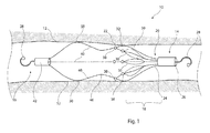
- FIG. 1 shows an embodiment of implantable medical device 10 deployed in the vena cava 12 of a patient.
- the medical device has a longitudinal dimension extending to first and second ends 14 and 16.
- the medical device 10 includes a material capture element 18 which has a generally closed conical deployed shape with a narrow end 20 disposed at or proximate the first end 14 of the device 10, and a wide end 22 facing the second end 16 of the device 10.
- the material capture element 18 in this embodiment is configured as a filter and is formed of a plurality of wires 24 arranged in the form of a cone having a narrow end in which the wires 24 pass into a metal bushing 26, in the form of a sleeve or cup. At the end of the bushing 26 there is provided a hook 28.
- the wires 24 may be welded, bonded or a friction fit, for example, to the inside of the lumen of the bushing 26 and the hook 28 may be likewise welded, bonded or otherwise formed as a part of the bushing 26.
- the wires 24 extend to the wide end 22 of the material capture element 18. It will be apparent to the skilled person that the wires 24 are preferably circumferentially equally spaced from one another.
- wires 24 there are provided eight wires 24 but their number will be dependent upon the deployed size of the device 10, the diameter of the wires 24 and the degree of filtering desired.
- the wires 24 preferably have a curved shape and are of a number which allows for minimum trauma to the vessel as the radial forces are distributed at several points.
- the bushing 26 is provided in this embodiment but is not essential as the wires could be coupled together is a different manner, for example by welding, by being cut forma common rod or cannula and so on.
- This shape of wires 24 and wire sections 30 creates apertures within the material capture element 18 which allow for the passage of fluid therethrough but which are small enough to trap particulate material, such as plaque, thrombus material and the like, within the material capture element 18.
- particulate material such as plaque, thrombus material and the like
- This structure is preferred in contrast to a filter having a frame and covering mesh as it has a smaller volume allowing it to be compressed radially to a smaller diameter, although it is not excluded that the material capture element 18 could be formed as a frame and covering mesh.
- the wires 24 of the material capture element 18 open radially from the first end 14 towards the wide end 22 in a generally linear manner, although in this embodiment curve slightly inwardly at the wide end 22, in a manner to create a first series of contact points 32 at the positions of maximum radius of the wires 24.
- the reader will appreciate that the wires 24 will create a plurality of contact points 32 arranged and spaced circumferentially around the wide end of the cone of the material capture element 18, these contact points 32 providing a first contact site of the device 10.
- the wire sections 30 are preferably disposed along the periphery of the cone of the material capture element 18 and thus define with the wires 24 the shape of the material capture element 18.
- the wires 24 and wire sections 30 may be formed from distinct wires of round cross-section but in other embodiments may be cut from a common blank, for example from a cannula or cone. Cutting can usefully be by laser.
- wires 24 and wire sections 30 as shown in the Figures provides a structure which is able to be compressed radially to a small diameter, useful for endoluminal delivery through a small diameter introducer assembly. This enables the device 10 to be delivered even through narrow and/or tortuous vessels.
- connection points 36, 38 could in some embodiments also be annular or other shaped supports for supporting one or more sets of radiopaque markers for locating the device 10 in a patient's vessel.
- a first set of radiopaque markers could be located at the junction 36 of the wire sections 30 to their respective wires 24 adjacent the wide end 22 of the material capture element 18.
- the second set of radiopaque markers could be located at the junction 38 of the wires 24 with respective wire tethers 40. It will be appreciated that only one set of radiopaque markers may be provided.
- radiopaque markers would typically be of gold or other radiopaque material and may be held within annular recesses or openings at the junctions 36, 38 in a manner known in the art.
- the wire tethers 40 extend to the second end 14 of the device 10 and in particular to a second bushing 42 which in this embodiment has the same characteristics as the bushing 26 and is equally provided with a hook 44.
- the second hook 44 faces the opposite direction relative to the first hook 28.
- the wire tethers 40 are circumferentially spaced around the circumference of the device 10.
- the wire tethers 40 there are provided eight wire tethers 40, although this number may be different. It is not necessary to have the same number of wire tethers 40 as wires 24, although having the same number provides a convenient structure.
- wire tethers 40 As will be apparent in particular from the uppermost and lowermost wire tethers 40 visible in Figure 1 , these have a curving shape in which they curve radially inwardly from their junction with the wires 24, or radiopaque markers 38, towards a point of minimum radius or waist 46 and then outwardly again towards a point of maximum radius 50, before tapering in substantially linear manner towards the second bushing 42 to form a generally conical end portion 52 to the wire tethers 40.
- the points of maximum radius 50 abut the vessel wall 12 at a second contact site longitudinally spaced from the first contact site 32.
- These two spaced contact sites 32, 50 ensure that the device 10 remains properly aligned in the vessel 12 with no risk of tilting, particularly of the material capture element 18. This positioning also ensures that the wide end 22 of the material capture element 18 is maintained aligned with the normal to the vessel, that is with a plane perpendicular to the centreline of the vessel 12.
- the wire tethers 40 have a generally open structure which provides a substantially open passageway for blood and particulate material therethrough. As a result, there is no impediment or disturbance to the flow of blood through the structure of the wire tethers 40. This will minimise the creation of stagnant blood at the wire tethers and will minimise blood clotting in this zone of the device 10. All significant blood disturbance occurs at and within the material capture element 18 and thus any clotting will be confined to this part of the device 10.
- the wires 24, 30 and 40 are advantageously made from metal alloys, including for example nickel titanium alloy such as Nitinol, cobalt chromium or any other alloys with good fatigue properties and good elastic performance.
- the wires could be formed of a spring material such as spring steel.
- Parts of the filter could be made of or include a biodegradeable material, such as magnesium or a plastic polymer for example. The person skilled in the art will be aware of suitable materials.
- the structure is double-ended, which enables deployment, repositioning and retrieval from both directions, as the device 10 can be deployed as well as collapsed and repositioned or withdrawn from the vessel from either end.
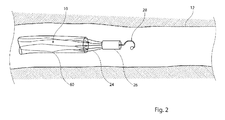
- FIG 2 shows in schematic form only the deployment of the device 10 into the vena cava 12 of a patient. This would typically be achieved by an introducer assembly of generally conventional form, in which the device 10 is held within a sheath 60.
- the introducer assembly will comprise a variety of components including, for example, pusher elements, constraining wires and the like for holding the medical device 10 radially constrained within the introducer assembly until it is to be deployed within a patient, as will be apparent to the person skilled in the art.
- the device 10 is typically deployed from the end 14 first, such that the material capture element 18 is expanded first from the introducer assembly.
- the device 10 is progressively released from the sheath 60, all the way to its second end 16.
- the device 10 can be pulled in either direction so as to achieve accurate positioning within the vessel 12.
- the device 10 can be removed from a patient's vessel from either end and in this regard in Figure 3 there is shown a removal assembly which includes a sheath 60 and a removal device 70 which includes a hook 72 able to hook onto, in this example, the second hook 44 of the medical device 10.
- a removal assembly which includes a sheath 60 and a removal device 70 which includes a hook 72 able to hook onto, in this example, the second hook 44 of the medical device 10.
- the embodiments described above form the filtration structure by means of an arrangement of wires 24, 30.
- Other embodiments can provide a filtration structure formed of a mesh of material which is held to a wire frame, in which case the wire structure of the filtration element 18 can have a similar structure to that of the wire tethers 44.
- the embodiments described above relate to a filter assembly, the structure can also be used as an occlusion device, in which case the material capture element 18, instead of filtering would occlude. This could be achieved, for example, by providing the structure 18 as a sheet of impermeable material or by covering a frame with an impermeable material, such as an impermeable fabric.
- the material capture element 18 could have a different structure, for example, a braided structure or the like.
- the wires 24, 30, 44 could be made of shape memory materials or spring materials.
- wire elements 20, 26 and 32 could be laser cut from a cannula.
Landscapes
- Health & Medical Sciences (AREA)
- Life Sciences & Earth Sciences (AREA)
- Engineering & Computer Science (AREA)
- Public Health (AREA)
- Veterinary Medicine (AREA)
- Biomedical Technology (AREA)
- Heart & Thoracic Surgery (AREA)
- Vascular Medicine (AREA)
- General Health & Medical Sciences (AREA)
- Animal Behavior & Ethology (AREA)
- Cardiology (AREA)
- Transplantation (AREA)
- Oral & Maxillofacial Surgery (AREA)
- Surgery (AREA)
- Reproductive Health (AREA)
- Nuclear Medicine, Radiotherapy & Molecular Imaging (AREA)
- Medical Informatics (AREA)
- Molecular Biology (AREA)
- Surgical Instruments (AREA)
Abstract
An implantable medical device, such as a vena cava filter (10) has first and second ends (14, 16). At one end (14) there is provided a material capture element (18) which has a generally closed conical deployed shape and a narrow end disposed at or proximate the first end (14) of the device (10). The material capture element (18) includes a wide end (22) which faces the second end (16) of the device (10), the material capture element (18) having a zone (32) of wider radial dimension which provides a first vessel contact site of the device (10). A plurality of wire tethers (40) are coupled to the material capture element (18) at its wide end and extend to the second end (16) of the device (10). The wire tethers (44) define a substantially open passageway for blood and particulate material and are provided with portions (50) of wider radial dimension which provide a second vessel contact site of the device (10). The first and second contact sites (32, 50) are spaced from one another in the longitudinal dimension of the device, to provide orientational stability of the device within a vessel (12). A first retrieval element (26) is disposed at the first end of the device and coupled to the narrow end of the material capture element (18), while a second retrieval element (28) is disposed at the second end of the device and coupled to the wire tethers (40). The medical device (10) can, as a result, be retrieved from either end and can also be repositioned once having been deployed in a vessel (12).
Description
- The present invention relates primarily to a vena cava filter although the structure of device taught herein can equally be used for an occlusion device. The skilled person will also appreciate that the device could be used in other parts of a patient's anatomy and not just in the vena cava.
- Filters for placement in the vena cava are well known. A preferred filter shape is conical and sized such that the wide end of the cone is sufficiently large to be able to abut and press against the vessel wall, often fixed thereto by barbs or similar anchoring devices. The narrow end of the filter is typically closed. The filter is often formed as a mesh of wires or struts having apertures which are sufficiently large to allow fluid therethrough but small enough to trap debris and thrombus material. A conical shape has the advantage that the cone tends to expand as a result of blood flow pressing into the filter, which thereby assists in holding the filter in place.
- A problem with such filter designs is that there is a risk of deploying the filter at an angle in the vessel, that is with the open end of the cone not properly aligned in the plane transverse to the vessel. Even if it is deployed accurately, there is the risk that the filter tilts over time. Any such tilt of the filter can result in loss of patency, or sealing, to the vessel wall and as a result loss of filtration function. Tilting can also cause loss of coupling to the vessel wall, which can result in migration of the filter over time. The art has sought to address these problems by modification of the delivery assembly, for instance to provide devices which seek to position the narrow end of the filter at the centre point of the vessel. Alternatively or additionally, the generally conical filter design may be modified by the addition of stabilising struts and the like, for instance by providing a double filter structure with opposing filter cones.
- While a specially designed deployment assembly may reduce or substantially avoid the risk of incorrect placement of the filter in a vessel, it has no further function after deployment and as a result cannot assist in maintaining proper orientation of the filter after deployment.
- The addition of further stabilising struts to a conical filter can add bulk to the structure, particularly when the filter is radially compressed for deployment purposes. Furthermore, known stabilising structures are such that they are liable to impinge on fluid flow, thereby risking the generation of thrombi. This can be particularly the case with double cone symmetrical filter designs.
- Moreover, vena cava and other filters tend to be temporary medical devices requiring removal once the period of treatment has been completed. A problem with conical shaped filters lies in the lack of options with regard to retrieval, in that they normally must be retrieved from their narrow or closed end first. In addition, conical shaped filters tend to be harder to reposition once deployed in the patient's vessel.
- The skilled person will appreciate that at least some of the above considerations can apply equally to occlusion devices of conical form.
- Examples of filters can be found in
WO-2006/074163 ,US-2012/0071914 ,WO-02/102280 US-2010/0030254 ,WO-95/13761 DE-29/500,864U . Examples of embolic protection devices can be found inUS-2010/0274277 ,US-2007/0066991 ,US-2007/0078481 andUS-2010/0211094 . - The present invention seeks to provide an improved implantable medical device and in the preferred embodiments an improved vena cava filter. It will be appreciated though that the teachings herein can be applied to filters for placement in other body vessels and also to occlusion devices. The teachings herein can also be applied to embolic protection devices.
- According to an aspect of the present invention, there is provided an implantable medical device having first and second ends and a longitudinal dimension, the device including: a material capture element having a generally closed conical deployed shape with a narrow end disposed at or proximate the first end of the device, and a wide end facing the second end of the device; the material capture element having a zone of wider radial dimension providing a first vessel contact site of the device; a plurality of wire tethers coupled to the capture element at the wide end thereof, the wire tethers extending to the second end of the device and defining a substantially open passageway for blood and particulate material therethrough; the wire tethers having portions of wider radial dimension providing a second vessel contact site of the device, the first and second contact sites being spaced from one another in the longitudinal dimension of the device; a first retrieval element disposed at the first end of the device and coupled to the narrow end of the capture element; and a second retrieval element disposed at the second end of the device and coupled to the wire tethers.
- This structure provides a number of advantages over the art. The wire tethers provide a second retrieval point for the medical device, which means that it can be retrieved from either end once implanted in a vessel. The two retrieval points also provide a structure which enables repositioning of the device after deployment.
- The shapes of the conical portion and of the wire tethers provide two longitudinally spaced contact sites along the length of the device, which give the device orientational stability in the vessel and minimises the risk of tilting of the device.
- Furthermore, the wire tethers do not impinge upon or disturb blood flow, thereby minimising the risk of thrombus formation at the tethers.
- In an embodiment, the capture element includes a frame having a plurality of frame elements extending to the open end of the capture element; the wire tethers being coupled to respective ones of the frame elements at the open end of the capture element.
- Preferably, the capture element provides a substantially closed conical capture basket.
- Advantageously, the wire tethers have a curved deployed shape providing the portions of wider radial dimension. Such a shape can reduce the risk of vessel damage or trauma.
- In an embodiment, the wide end of the capture element has a taper, which taper provides the zone of wider radial dimension and first vessel contact site.
- It is preferred that the first and second contact sites each include circumferentially spaced contact elements.
- It is not excluded that the device could be provided with more than two contact sites along the length of the device, the contact sites being spaced form one another.
- Advantageously, the wire tethers taper to the second end of the device.
- In the preferred embodiments, the first and second retrieval elements face opposing directions. The first and second retrieval elements may include a retrieval hook or catch.
- Preferably, the device is a filter, in particular a vena cava filter.
- According to another aspect of the present invention, there is provided a method of deploying an implantable medical device, the device having first and second ends and including a material capture element having a generally closed conical deployed shape with a narrow end disposed at or proximate the first end of the device, and a wide end facing the second end of the device; the material capture element having a zone of wider radial dimension providing a first vessel contact site of the device; a plurality of wire tethers coupled to the capture element at the wide end thereof, the wire tethers extending to the second end of the device and defining a substantially open passageway for blood and particulate material therethrough; the wire tethers having portions of wider radial dimension providing a second vessel contact site of the device, the first and second contact sites being spaced from one another in the longitudinal dimension of the device; a first retrieval element disposed at the first end of the device and coupled to the narrow end of the capture element; and a second retrieval element disposed at the second end of the device and coupled to the wire tethers; the method including the steps of:
- inserting the device endoluminally in a patient in a radially contracted configuration; providing for expansion of the device in a vessel of the patient with the second end of the device in a downstream blood flow position relative to the second end of the device such that the capture element is disposed with the open end thereof facing upstream; whereby the first and second contact sites maintain orientation of the device in the vessel.
- The method may include the step of subsequently retrieving the medical device from the patient by coupling a retrieval apparatus to the second retrieval element from an upstream direction of the vessel, the retrieval apparatus including a sheath sized to receive the medical device, the wire tethers acting to pull and radially compress the capture element into the sheath.
- Other features and advantages will become apparent from the following detailed description of the preferred embodiments.
- Embodiments of the present invention are described below, by way of example only, with reference to the accompanying drawings, in which:
-
Figure 1 shows in schematic form a preferred embodiment of vena cava filter deployed in a patient; -
Figure 2 shows the filter ofFigure 1 in the process of being deployed from an introducer assembly; and -
Figure 3 shows the filter ofFigure 1 in the process of being retrieved from the vena cava of a patient. - There is described below a preferred embodiment of the present invention, which is configured as a vena cava filter. It is to be understood though that the teachings herein are not limited to vena cava filters and are equally applicable to filters disposed in other body lumens and can also be modified to form an occlusion device or an embolic protection device.
- Referring first to
Figure 1 , this shows an embodiment of implantablemedical device 10 deployed in thevena cava 12 of a patient. The medical device has a longitudinal dimension extending to first andsecond ends medical device 10 includes amaterial capture element 18 which has a generally closed conical deployed shape with anarrow end 20 disposed at or proximate thefirst end 14 of thedevice 10, and awide end 22 facing thesecond end 16 of thedevice 10. - The
material capture element 18 in this embodiment is configured as a filter and is formed of a plurality ofwires 24 arranged in the form of a cone having a narrow end in which thewires 24 pass into ametal bushing 26, in the form of a sleeve or cup. At the end of the bushing 26 there is provided ahook 28. Thewires 24 may be welded, bonded or a friction fit, for example, to the inside of the lumen of thebushing 26 and thehook 28 may be likewise welded, bonded or otherwise formed as a part of thebushing 26. Thewires 24 extend to thewide end 22 of thematerial capture element 18. It will be apparent to the skilled person that thewires 24 are preferably circumferentially equally spaced from one another. In the example shown inFigure 1 , there are provided eightwires 24 but their number will be dependent upon the deployed size of thedevice 10, the diameter of thewires 24 and the degree of filtering desired. Thewires 24 preferably have a curved shape and are of a number which allows for minimum trauma to the vessel as the radial forces are distributed at several points. - The
bushing 26 is provided in this embodiment but is not essential as the wires could be coupled together is a different manner, for example by welding, by being cut forma common rod or cannula and so on. - As can be seen in
Figure 1 , extending from and attached to thewires 24 arewire sections 30 which extend in curved manner so as to close the gap between thewires 24 towards thewider end 22 of thematerial capture element 18. In the example shown inFigure 1 , there are provided twowire sections 30 to eachwire 24 and these extend in opposing directions in what could be described as a leaf shape. Thewire sections 30 may be welded or otherwise bonded at their ends to their associatedwire 24. In other embodiments they could be cut from a common metal blank. In other embodiments, thewire sections 30 may simply be wrapped or coiled around the associatedwires 24.Elements wires 30 to thewires 24 and of thewires 40 to thewires 24, respectively. - This shape of
wires 24 andwire sections 30 creates apertures within thematerial capture element 18 which allow for the passage of fluid therethrough but which are small enough to trap particulate material, such as plaque, thrombus material and the like, within thematerial capture element 18. The skilled person will be aware of the optimum size of the apertures of such a filter and thus of the sizes, number ofwires material capture element 18. This structure is preferred in contrast to a filter having a frame and covering mesh as it has a smaller volume allowing it to be compressed radially to a smaller diameter, although it is not excluded that thematerial capture element 18 could be formed as a frame and covering mesh. - The
wires 24 of thematerial capture element 18 open radially from thefirst end 14 towards thewide end 22 in a generally linear manner, although in this embodiment curve slightly inwardly at thewide end 22, in a manner to create a first series of contact points 32 at the positions of maximum radius of thewires 24. The reader will appreciate that thewires 24 will create a plurality of contact points 32 arranged and spaced circumferentially around the wide end of the cone of thematerial capture element 18, these contact points 32 providing a first contact site of thedevice 10. - The
wire sections 30 are preferably disposed along the periphery of the cone of thematerial capture element 18 and thus define with thewires 24 the shape of thematerial capture element 18. - The
wires 24 andwire sections 30 may be formed from distinct wires of round cross-section but in other embodiments may be cut from a common blank, for example from a cannula or cone. Cutting can usefully be by laser. - The configuration of
wires 24 andwire sections 30 as shown in the Figures provides a structure which is able to be compressed radially to a small diameter, useful for endoluminal delivery through a small diameter introducer assembly. This enables thedevice 10 to be delivered even through narrow and/or tortuous vessels. - Either or both of the connection points 36, 38 could in some embodiments also be annular or other shaped supports for supporting one or more sets of radiopaque markers for locating the
device 10 in a patient's vessel. A first set of radiopaque markers could be located at thejunction 36 of thewire sections 30 to theirrespective wires 24 adjacent thewide end 22 of thematerial capture element 18. The second set of radiopaque markers could be located at thejunction 38 of thewires 24 with respective wire tethers 40. It will be appreciated that only one set of radiopaque markers may be provided. - Such radiopaque markers would typically be of gold or other radiopaque material and may be held within annular recesses or openings at the
junctions - The wire tethers 40 extend to the
second end 14 of thedevice 10 and in particular to asecond bushing 42 which in this embodiment has the same characteristics as thebushing 26 and is equally provided with ahook 44. Thesecond hook 44 faces the opposite direction relative to thefirst hook 28. - As with the
wires 24, the wire tethers 40 are circumferentially spaced around the circumference of thedevice 10. In the example shown inFigure 1 , there are provided eightwire tethers 40, although this number may be different. It is not necessary to have the same number of wire tethers 40 aswires 24, although having the same number provides a convenient structure. As will be apparent in particular from the uppermost and lowermost wire tethers 40 visible inFigure 1 , these have a curving shape in which they curve radially inwardly from their junction with thewires 24, orradiopaque markers 38, towards a point of minimum radius orwaist 46 and then outwardly again towards a point ofmaximum radius 50, before tapering in substantially linear manner towards thesecond bushing 42 to form a generallyconical end portion 52 to the wire tethers 40. - As can be seen particularly in
Figure 1 , the points ofmaximum radius 50 abut thevessel wall 12 at a second contact site longitudinally spaced from thefirst contact site 32. These two spacedcontact sites device 10 remains properly aligned in thevessel 12 with no risk of tilting, particularly of thematerial capture element 18. This positioning also ensures that thewide end 22 of thematerial capture element 18 is maintained aligned with the normal to the vessel, that is with a plane perpendicular to the centreline of thevessel 12. - The wire tethers 40 have a generally open structure which provides a substantially open passageway for blood and particulate material therethrough. As a result, there is no impediment or disturbance to the flow of blood through the structure of the wire tethers 40. This will minimise the creation of stagnant blood at the wire tethers and will minimise blood clotting in this zone of the
device 10. All significant blood disturbance occurs at and within thematerial capture element 18 and thus any clotting will be confined to this part of thedevice 10. - The
wires - In addition to improving the stability of the
medical device 10 in a patient, the structure is double-ended, which enables deployment, repositioning and retrieval from both directions, as thedevice 10 can be deployed as well as collapsed and repositioned or withdrawn from the vessel from either end. Referring toFigure 2 , this shows in schematic form only the deployment of thedevice 10 into thevena cava 12 of a patient. This would typically be achieved by an introducer assembly of generally conventional form, in which thedevice 10 is held within asheath 60. The introducer assembly will comprise a variety of components including, for example, pusher elements, constraining wires and the like for holding themedical device 10 radially constrained within the introducer assembly until it is to be deployed within a patient, as will be apparent to the person skilled in the art. - The
device 10 is typically deployed from theend 14 first, such that thematerial capture element 18 is expanded first from the introducer assembly. Thedevice 10 is progressively released from thesheath 60, all the way to itssecond end 16. Once deployed from the introducer assembly, it is still possible to reposition themedical device 10, for example by pulling from either end of thedevice 10 by means of therespective hook medical device 10, this will draw the wire elements of thedevice 10 radially inwardly effectively reducing its diameter, thereby assisting moving the device within the vessel. Thedevice 10 can be pulled in either direction so as to achieve accurate positioning within thevessel 12. - Similarly, the
device 10 can be removed from a patient's vessel from either end and in this regard inFigure 3 there is shown a removal assembly which includes asheath 60 and aremoval device 70 which includes ahook 72 able to hook onto, in this example, thesecond hook 44 of themedical device 10. By retracting theretrieval device 70 within thesheath 60, themedical device 10 will be progressively pulled into thesheath 60, with in this example the wire tethers 40 eventually being radially compressed into thesheath 60. The radial compression of the wire tethers 40 will also compress radially thematerial capture element 18 so that the entiremedical device 10 can be entirely drawn into thesheath 60. - The provision of
double hooks medical device 10 to be drawn into aretrieval sheath 60 from theend 14 of thedevice 10, that is from thematerial capture element 10 first. - It is to be appreciated that one or more of the
hooks device 10 could potentially just be welded to a deployment/retrieval device as an alternative. - The embodiments described above form the filtration structure by means of an arrangement of
wires filtration element 18 can have a similar structure to that of the wire tethers 44. Similarly, although the embodiments described above relate to a filter assembly, the structure can also be used as an occlusion device, in which case thematerial capture element 18, instead of filtering would occlude. This could be achieved, for example, by providing thestructure 18 as a sheet of impermeable material or by covering a frame with an impermeable material, such as an impermeable fabric. - In other embodiments, the
material capture element 18 could have a different structure, for example, a braided structure or the like. - The
wires - It will be appreciated also that the
wire elements - In some embodiments there may be provided barbs or other anchor elements, typically extending from the
wires device 10 in thevessel 12. Such anchors or barbs could usefully be located at either or both of the contact positions 32 and 50 and extending from thewires - A typical dimension for vena cava filter would be a diameter of around 30 mm when radially expanded and a length of around 50 mm.
- All optional and preferred features and modifications of the described embodiments and dependent claims are usable in all aspects of the invention taught herein. Furthermore, the individual features of the dependent claims, as well as all optional and preferred features and modifications of the described embodiments are combinable and interchangeable with one another.
- The disclosures in British patent application number
GB1316019.7
Claims (13)
- An implantable medical device having first and second ends and a longitudinal dimension, the device including:a material capture element having a generally closed conical deployed shape with a narrow end disposed at or proximate the first end of the device, and a wide end facing the second end of the device; the material capture element having a zone of wider radial dimension providing a first vessel contact site of the device;a plurality of wire tethers coupled to the material capture element at the wide end thereof, the wire tethers extending to the second end of the device and defining a substantially open passageway for blood and particulate material therethrough; the wire tethers having portions of wider radial dimension providing a second vessel contact site of the device, the first and second contact sites being spaced from one another along the longitudinal dimension of the device;a first retrieval element disposed at the first end of the device and coupled to the narrow end of the capture element; anda second retrieval element disposed at the second end of the device and coupled to the wire tethers.
- An implantable medical device according to claim 1, wherein the material capture element includes a frame having a plurality of frame elements extending to the open end of the material capture element; the wire tethers being coupled to respective ones of the frame elements at the open end of the material capture element.
- An implantable medical device according to claim 1 or 2, wherein the material capture element provides a substantially closed conical capture basket.
- An implantable medical device according to any preceding claim, wherein the wire tethers have a curved deployed shape providing said portions of wider radial dimension.
- An implantable medical device according to any preceding claim, wherein the wide end of the material capture element has a taper, said taper providing the zone of wider radial dimension and first vessel contact site.
- An implantable medical device according to any preceding claim, wherein the first and second contact sites each include circumferentially spaced contact elements.
- An implantable medical device according to any preceding claim, including more than two contact sites along the length of the device, the contact sites being spaced from one another.
- An implantable medical device according to any preceding claim, wherein the wire tethers taper to the second end of the device.
- An implantable medical device according to any preceding claim, wherein the first and second retrieval elements face opposing directions.
- An implantable medical device according to any preceding claim, wherein the first and second retrieval elements include a retrieval hook.
- An implantable medical device according to any preceding claim, wherein the device is a filter.
- A method of deploying an implantable medical device, the device having first and second ends and including:a material capture element having a generally closed conical deployed shape with a narrow end disposed at or proximate the first end of the device, and a wide end facing the second end of the device; the material capture element having a zone of wider radial dimension providing a first vessel contact site of the device;a plurality of wire tethers coupled to the capture element at the wide end thereof, the wire tethers extending to the second end of the device and defining a substantially open passageway for blood and particulate material therethrough; the wire tethers having portions of wider radial dimension providing a second vessel contact site of the device, the first and second contact sites being spaced from one another along the longitudinal dimension of the device;a first retrieval element disposed at the first end of the device and coupled to the narrow end of the capture element; anda second retrieval element disposed at the second end of the device and coupled to the wire tethers; the method including the steps of:inserting the device endoluminally in a patient in a radially contracted configuration;providing for expansion of the device in a vessel of the patient with the second end of the device in a downstream blood flow position relative to the second end of the device such that the material capture element is disposed with the open end thereof facing upstream; whereby the first and second contact sites maintain orientation of the device in the vessel.
- A method according to claim 12, including the step of subsequently retrieving the medical device from the patient by coupling a retrieval apparatus to the second retrieval element from an upstream direction of the vessel, the retrieval apparatus including a sheath sized to receive the medical device, the wire tethers acting to pull and radially compress the material capture element into the sheath.
Applications Claiming Priority (1)
| Application Number | Priority Date | Filing Date | Title |
|---|---|---|---|
| GB1316019.7A GB2517992A (en) | 2013-09-09 | 2013-09-09 | Vena cava filter |
Publications (1)
| Publication Number | Publication Date |
|---|---|
| EP2845567A1 true EP2845567A1 (en) | 2015-03-11 |
Family
ID=49486934
Family Applications (1)
| Application Number | Title | Priority Date | Filing Date |
|---|---|---|---|
| EP14275184.1A Withdrawn EP2845567A1 (en) | 2013-09-09 | 2014-09-03 | Vena cava filter |
Country Status (3)
| Country | Link |
|---|---|
| US (1) | US10231814B2 (en) |
| EP (1) | EP2845567A1 (en) |
| GB (1) | GB2517992A (en) |
Cited By (3)
| Publication number | Priority date | Publication date | Assignee | Title |
|---|---|---|---|---|
| CN104970900A (en) * | 2015-06-26 | 2015-10-14 | 深圳市科奕顿生物医疗科技有限公司 | Filter capable of recycling thrombi |
| CN109771092A (en) * | 2019-03-26 | 2019-05-21 | 李莹 | A kind of vena cave implantation novel thrombus filter |
| CN109953839A (en) * | 2017-12-26 | 2019-07-02 | 先健科技(深圳)有限公司 | filter |
Families Citing this family (7)
| Publication number | Priority date | Publication date | Assignee | Title |
|---|---|---|---|---|
| US20160089255A1 (en) * | 2014-09-26 | 2016-03-31 | Anaxiom Corporation | Removable vascular occlusion device |
| CN105662646A (en) * | 2015-12-29 | 2016-06-15 | 先健科技(深圳)有限公司 | Filter |
| US11389283B2 (en) * | 2016-05-11 | 2022-07-19 | W. L. Gore & Associates, Inc. | Filter and occluder systems and associated methods and devices |
| WO2018220589A1 (en) * | 2017-06-02 | 2018-12-06 | HemoDynamx Technologies, Ltd. | Flow modification in body lumens |
| US12409024B2 (en) | 2018-11-26 | 2025-09-09 | Nephronyx Ltd. | Flow modification devices in body lumens |
| CN110063814A (en) * | 2019-05-16 | 2019-07-30 | 山西职业技术学院 | A kind of calabash shape vena cava filter |
| WO2021240411A1 (en) | 2020-05-28 | 2021-12-02 | Nephronyx Ltd. | Acute and chronic devices for modifying flow in body lumens and methods of use thereof |
Citations (5)
| Publication number | Priority date | Publication date | Assignee | Title |
|---|---|---|---|---|
| WO2003002032A2 (en) * | 2001-06-29 | 2003-01-09 | Advanced Cardiovascular Systems, Inc. | Filter device for embolic protection system |
| US20050131452A1 (en) * | 2000-02-08 | 2005-06-16 | Walak Steven E. | Recoilable thrombosis filtering device and method |
| US20130006295A1 (en) * | 2002-02-20 | 2013-01-03 | Chanduszko Andrzej J | IVC Filter with Translating Hooks |
| EP2604222A1 (en) * | 2011-12-16 | 2013-06-19 | Cook Medical Technologies LLC | Vena cava filter with bidirectional retrieval |
| US20130226224A1 (en) * | 2012-02-23 | 2013-08-29 | Merit Medical Systems, Inc. | Vascular filter |
Family Cites Families (20)
| Publication number | Priority date | Publication date | Assignee | Title |
|---|---|---|---|---|
| US4807626A (en) * | 1985-02-14 | 1989-02-28 | Mcgirr Douglas B | Stone extractor and method |
| GB2238485B (en) * | 1989-11-28 | 1993-07-14 | Cook William Europ | A collapsible filter for introduction in a blood vessel of a patient |
| DE4339265A1 (en) | 1993-11-18 | 1995-05-24 | Angiomed Ag | Vena cava filter |
| DE29500864U1 (en) | 1995-01-20 | 1996-05-23 | Waggershauser, Tobias, Dr.med., 81669 München | Kava filter |
| US6818006B2 (en) * | 2001-04-03 | 2004-11-16 | Medtronic Vascular, Inc. | Temporary intraluminal filter guidewire |
| JP4294470B2 (en) * | 2001-06-14 | 2009-07-15 | クック インコーポレイテッド | Intravascular filter |
| AU2002312441B8 (en) | 2001-06-18 | 2008-08-21 | Rex Medical, L.P. | Vein Filter |
| WO2003030740A1 (en) * | 2001-09-28 | 2003-04-17 | Kanji Inoue | Free thrombus capturing tool |
| US8262689B2 (en) * | 2001-09-28 | 2012-09-11 | Advanced Cardiovascular Systems, Inc. | Embolic filtering devices |
| WO2008051294A2 (en) * | 2006-05-02 | 2008-05-02 | C. R. Bard, Inc. | Ivc filter with translating hooks |
| US8535344B2 (en) * | 2003-09-12 | 2013-09-17 | Rubicon Medical, Inc. | Methods, systems, and devices for providing embolic protection and removing embolic material |
| US7803171B1 (en) * | 2004-06-14 | 2010-09-28 | Uflacker Renan P | Retrievable inferior vena cava filter |
| US7279000B2 (en) * | 2004-09-29 | 2007-10-09 | Angiodynamics Inc | Permanent blood clot filter with capability of being retrieved |
| US20060241678A1 (en) | 2005-01-03 | 2006-10-26 | Eric Johnson | Retrievable endoluminal filter |
| US8377092B2 (en) | 2005-09-16 | 2013-02-19 | Cook Medical Technologies Llc | Embolic protection device |
| US8182508B2 (en) | 2005-10-04 | 2012-05-22 | Cook Medical Technologies Llc | Embolic protection device |
| CA2655158A1 (en) | 2006-06-05 | 2007-12-13 | C.R. Bard Inc. | Embolus blood clot filter utilizable with a single delivery system or a single retrieval system in one of a femoral or jugular access |
| WO2010077963A1 (en) | 2008-12-17 | 2010-07-08 | Abbott Laboratories Vascular Enterprises Limited | Implantable lumen filter with enhanced durability |
| US20100211094A1 (en) | 2009-02-18 | 2010-08-19 | Cook Incorporated | Umbrella distal embolic protection device |
| US20100274277A1 (en) | 2009-04-27 | 2010-10-28 | Cook Incorporated | Embolic protection device with maximized flow-through |
-
2013
- 2013-09-09 GB GB1316019.7A patent/GB2517992A/en not_active Withdrawn
-
2014
- 2014-09-03 EP EP14275184.1A patent/EP2845567A1/en not_active Withdrawn
- 2014-09-09 US US14/480,930 patent/US10231814B2/en active Active
Patent Citations (5)
| Publication number | Priority date | Publication date | Assignee | Title |
|---|---|---|---|---|
| US20050131452A1 (en) * | 2000-02-08 | 2005-06-16 | Walak Steven E. | Recoilable thrombosis filtering device and method |
| WO2003002032A2 (en) * | 2001-06-29 | 2003-01-09 | Advanced Cardiovascular Systems, Inc. | Filter device for embolic protection system |
| US20130006295A1 (en) * | 2002-02-20 | 2013-01-03 | Chanduszko Andrzej J | IVC Filter with Translating Hooks |
| EP2604222A1 (en) * | 2011-12-16 | 2013-06-19 | Cook Medical Technologies LLC | Vena cava filter with bidirectional retrieval |
| US20130226224A1 (en) * | 2012-02-23 | 2013-08-29 | Merit Medical Systems, Inc. | Vascular filter |
Cited By (4)
| Publication number | Priority date | Publication date | Assignee | Title |
|---|---|---|---|---|
| CN104970900A (en) * | 2015-06-26 | 2015-10-14 | 深圳市科奕顿生物医疗科技有限公司 | Filter capable of recycling thrombi |
| CN104970900B (en) * | 2015-06-26 | 2017-10-17 | 深圳市科奕顿生物医疗科技有限公司 | Recyclable thrombus filter |
| CN109953839A (en) * | 2017-12-26 | 2019-07-02 | 先健科技(深圳)有限公司 | filter |
| CN109771092A (en) * | 2019-03-26 | 2019-05-21 | 李莹 | A kind of vena cave implantation novel thrombus filter |
Also Published As
| Publication number | Publication date |
|---|---|
| GB2517992A (en) | 2015-03-11 |
| US20150073470A1 (en) | 2015-03-12 |
| GB201316019D0 (en) | 2013-10-23 |
| US10231814B2 (en) | 2019-03-19 |
Similar Documents
| Publication | Publication Date | Title |
|---|---|---|
| US10231814B2 (en) | Vena cava filter | |
| EP3505136B1 (en) | Tubular filter | |
| US6214025B1 (en) | Self-centering, self-expanding and retrievable vena cava filter | |
| CN101031254B (en) | Removable vena cava filter including struts with axial bends | |
| US20060095068A1 (en) | Retrievable vena cava filter | |
| EP1755726B1 (en) | Asymmetrical medical filter | |
| US8353926B2 (en) | Long-term retrievable medical filter | |
| JP2009523582A (en) | Clot filter that can be taken out | |
| EP2939614A1 (en) | Implantable medical device with twisted element | |
| JP2019072504A (en) | Vascular filter device | |
| US10507023B2 (en) | Self-centering spiral filter | |
| US20160081785A1 (en) | Spring lock implantable vascular device | |
| US9788932B2 (en) | Vascular filter | |
| US8317818B2 (en) | Removable blood clot filter with edge for cutting through the endothelium | |
| US9452039B2 (en) | Vascular filter | |
| EP3184077B1 (en) | Filter device for implantation into a body vessel | |
| US10695158B2 (en) | Implantable medical device with improved orientation | |
| US20220218459A1 (en) | Self-cleaning aortic blood filter | |
| US20230157803A1 (en) | Non-tavr left-sided heart procedure embolic particle protection device |
Legal Events
| Date | Code | Title | Description |
|---|---|---|---|
| 17P | Request for examination filed |
Effective date: 20140903 |
|
| AK | Designated contracting states |
Kind code of ref document: A1 Designated state(s): AL AT BE BG CH CY CZ DE DK EE ES FI FR GB GR HR HU IE IS IT LI LT LU LV MC MK MT NL NO PL PT RO RS SE SI SK SM TR |
|
| AX | Request for extension of the european patent |
Extension state: BA ME |
|
| PUAI | Public reference made under article 153(3) epc to a published international application that has entered the european phase |
Free format text: ORIGINAL CODE: 0009012 |
|
| STAA | Information on the status of an ep patent application or granted ep patent |
Free format text: STATUS: THE APPLICATION IS DEEMED TO BE WITHDRAWN |
|
| 18D | Application deemed to be withdrawn |
Effective date: 20150912 |