EP2845271B1 - Electrical contact with sealing web - Google Patents
Electrical contact with sealing web Download PDFInfo
- Publication number
- EP2845271B1 EP2845271B1 EP13714661.9A EP13714661A EP2845271B1 EP 2845271 B1 EP2845271 B1 EP 2845271B1 EP 13714661 A EP13714661 A EP 13714661A EP 2845271 B1 EP2845271 B1 EP 2845271B1
- Authority
- EP
- European Patent Office
- Prior art keywords
- conductor
- webs
- electrical contact
- housing
- lateral faces
- Prior art date
- Legal status (The legal status is an assumption and is not a legal conclusion. Google has not performed a legal analysis and makes no representation as to the accuracy of the status listed.)
- Active
Links
Images
Classifications
-
- H—ELECTRICITY
- H01—ELECTRIC ELEMENTS
- H01R—ELECTRICALLY-CONDUCTIVE CONNECTIONS; STRUCTURAL ASSOCIATIONS OF A PLURALITY OF MUTUALLY-INSULATED ELECTRICAL CONNECTING ELEMENTS; COUPLING DEVICES; CURRENT COLLECTORS
- H01R13/00—Details of coupling devices of the kinds covered by groups H01R12/70 or H01R24/00 - H01R33/00
- H01R13/40—Securing contact members in or to a base or case; Insulating of contact members
- H01R13/405—Securing in non-demountable manner, e.g. moulding, riveting
- H01R13/41—Securing in non-demountable manner, e.g. moulding, riveting by frictional grip in grommet, panel or base
-
- H—ELECTRICITY
- H01—ELECTRIC ELEMENTS
- H01R—ELECTRICALLY-CONDUCTIVE CONNECTIONS; STRUCTURAL ASSOCIATIONS OF A PLURALITY OF MUTUALLY-INSULATED ELECTRICAL CONNECTING ELEMENTS; COUPLING DEVICES; CURRENT COLLECTORS
- H01R13/00—Details of coupling devices of the kinds covered by groups H01R12/70 or H01R24/00 - H01R33/00
- H01R13/46—Bases; Cases
- H01R13/52—Dustproof, splashproof, drip-proof, waterproof, or flameproof cases
- H01R13/521—Sealing between contact members and housing, e.g. sealing insert
-
- H—ELECTRICITY
- H01—ELECTRIC ELEMENTS
- H01R—ELECTRICALLY-CONDUCTIVE CONNECTIONS; STRUCTURAL ASSOCIATIONS OF A PLURALITY OF MUTUALLY-INSULATED ELECTRICAL CONNECTING ELEMENTS; COUPLING DEVICES; CURRENT COLLECTORS
- H01R13/00—Details of coupling devices of the kinds covered by groups H01R12/70 or H01R24/00 - H01R33/00
- H01R13/46—Bases; Cases
- H01R13/52—Dustproof, splashproof, drip-proof, waterproof, or flameproof cases
- H01R13/5216—Dustproof, splashproof, drip-proof, waterproof, or flameproof cases characterised by the sealing material, e.g. gels or resins
Definitions
- the invention relates to an electrical contact according to patent claim 1.
- An object of the invention is to provide an improved electrical contact.
- US 5 873 752 discloses a tow socket connector having sealant, wherein the tow socket connector is provided for receiving a plug form a towed vehicle and having multiple electrical terminals sealed actually through the socket from one side to the other.
- Each terminal is locked in its associated opening in the connector by a snap member and the thickness of each terminal is expanded by jogs formed along a portion of its length to provide a slight fit and a sealant block between the terminal and its opening.
- Each terminal includes a horizontal opening to permit the flow of sealant in a well formed at the upper hand of the socket.
- JP H03 30387 U discloses an electrical connector with a housing with a recess, wherein in the recess an electrical connector is arranged.
- the electrical connector is made of a double folded plate, wherein a connector section is formed by folded parts of the connector.
- the connector section provides four lateral walls which are adjacent at side surfaces of the recess of the housing.
- JP 3 3651338 B1 and JP H09 147968 A disclose further electrical connectors, wherein electrical conductors are embedded in housings, wherein in one side of the housing a sealing material is arranged sealing the connectors at this side of the housing.
- WO 2008/075802 A1 discloses an electronic part with an external appearance defined by a case.
- the case is formed with a through-hole for allowing an internal space of the case to communicate with the outside, and a terminal is installed through the through-hole.
- the terminal electrically connects devices within the case with the outside.
- the case may be manufactured from a plurality of pieces. Sealants are applied to a gap between the through-hole of the case and the terminal and around the through-hole and also two portions, where the plurality of pieces of the case are combined together.
- US 5,885,114 discloses a connector for automatic transmission.
- the connector comprises a housing with a plurality of cavities for receiving terminals.
- the cavities are separated from one another in such a manner that the cavities communicate with one another through partially notched wall portions.
- the housing has terminal passage holes into which the terminals are press-fitted.
- a rear side of the housing is filled with resin material.
- US 5,000,695 discloses a female connector with a holder that serves to hold a female terminal.
- the holder is made of resin or rubber having elasticity.
- the holder comprises at an outer peripheral surface two circumferentially extending parallel raised portions defining a recessed portion in between. The raised portions contact an inner wall of a case in which the holder is arranged. Adjacent to the holder, a sealing member is arranged within the case.
- EP 0 574 862 A2 discloses a sealed electrical connector with a housing, wherein a cable is arranged within the housing. Between the cable and the housing, a sealing member is arranged. Furthermore, an insert seal is arranged adjacent to the sealing member.
- An advantage of the electrical contact described is that sealing material which is provided to seal an intermediate space between the electrical conductor and the housing is securely retained in a fixed region of the housing.
- the electrical conductor having a web which is arranged transversely relative to a longitudinal direction of the conductor and which protrudes by a predetermined height above a side face of the electrical conductor. Consequently, in the assembled state of the conductor, the web abuts the housing so that a flow blocking member for the sealing material is produced by means of the web. Owing to the formation of the web, on the one hand, a flow blocking member is produced and, on the other hand, owing to the free space between the conductor and the housing, simple and reliable assembly of the conductor in the housing is possible.
- the sealing material can be introduced into the free space, that is to say, in the intermediate space between the conductor and the housing.
- the web protrudes to such an extent beyond the lateral face of the conductor that the web abuts a wall of the housing in a sealing manner.
- the conductor has four lateral faces, a web being arranged on each of the four lateral faces, respectively.
- sealing material it is possible to apply sealing material to four lateral faces of the conductor, without the sealing material being able to flow into inadmissible regions.
- Owing to the formation of the webs on the lateral faces of the conductor a sealing of the intermediate space in the conducting housing is possible at all four lateral faces of the conductor, without the sealing material being able to flow beyond the regions delimited by the webs. Consequently, reliable and fluid-tight embedding of the conductor in the housing is enabled.
- two identical webs are formed at two opposing lateral faces, respectively, the two types of web being constructed differently.
- the type of webs can be adapted to the width of the lateral face.
- Tests have shown that webs which protrude to a relatively large extent beyond the lateral face on narrow lateral faces are hardly disadvantageous for the assembly and the function of the electrical contact. Consequently, on the narrow lateral faces, webs which protrude further from the lateral face can be provided.
- tests have shown that the webs on the wider lateral faces are not intended to extend too far beyond the lateral face of the conductor since assembly is otherwise made more difficult.
- the webs preferably protrude on the wider lateral faces to such an extent beyond the lateral faces that the webs in the assembled state of the conductor touch the associated inner walls of the housing.
- in the assembled state there may also be a small spacing between the webs of the wide lateral faces and the associated housing walls.
- the sealing material is prevented from flowing past the web.
- the conductor has a groove parallel with the construction of the web.
- the combination of the web and groove forms an improved flow resistance for the sealing material.
- a particularly thick layer of sealing material is introduced. Consequently, improved sealing is achieved which in particular ensures improved sealing against impediments such as impacts, temperature fluctuations, deviations from standard geometries.
- an electrical conductor has a groove at both sides of the web.
- the groove has two lateral faces, the lateral faces being arranged substantially parallel with the longitudinal extent of the web, that is to say, transversely relative to the longitudinal direction of the conductor.
- the two lateral faces of the groove have different inclinations relative to the lateral face of the conductor.
- the lateral face of the groove which is adjacent to the web has a shallower inclination than the lateral face directed away from the web. In this manner, improved influx and filling of the groove with sealing material are enabled.
- the sealing is improved by the special configuration of the lateral faces of the groove.
- the flatter lateral face of the groove has a larger width than the steeper lateral face of the groove.
- the two lateral faces of the groove have an opening angle between 50° and 80°, for example 65°, in a direction perpendicular relative to the groove.
- This opening angle of the groove leads, on the one hand, to good filling of the groove with sealing material and, on the other hand, to reliable and robust sealing of the intermediate space between the conductor and the housing.
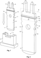
- Figure 1 is a perspective view of an electrical conductor 1 and a housing 2, the housing 2 having a recess 3 for receiving the electrical conductor 1.
- the housing 2 is, for example, formed from a plastics material.
- the electrical conductor 1 is, for example, produced as a punched component from a metal sheet and has a contact tongue 4 at a first end and contact pins 5 at the opposing second end.
- the conductor 1 is of a rectangular cross-section.
- the conductor 1 is of an elongate strip form, two wide lateral faces, that is to say, an upper side 6 and a lower side 7, being opposite each other in a parallel manner. At the sides of the upper side and the lower side 6, 7, there are formed narrow lateral faces 8, 9 which are arranged parallel with each other.
- the webs 15, 16 and the grooves 17, 18 are preferably introduced into the conductor 1 by means of a pressing operation.
- Figure 2 is an enlarged view of the conductor.
- the width of the contact tongue 4 is constant as far as the central region of the conductor 1.
- the lateral faces 8, 9 have a first recess 10.
- a third catch projection 14 which is also formed on the first and second lateral face 8, 9.
- the first and the second catch projections 12, 13 serve to lock the conductor 1 in the housing 2.
- the first and second lateral faces 8, 9 are constructed in an identical manner.
- a web 15, 16 is formed on the upper and lower side 6, 7, respectively.
- the third catch projections 14 of the two lateral faces 8, 9 and the first and second webs 15, 16 of the upper and lower side 6, 7 which are arranged at the same height form a flow blocking member which is arranged so as to extend around the conductor 1.
- Figure 3 is an enlarged view of the cutout of the conductor 1 in the region of the webs 15, 16 and the third catch projections 14.
- a first or a second groove 17, 18 is formed at both sides of each web 15, 16 in the upper side 6 and in the lower side 7.
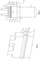
- Figure 4 is a cross-section through an electrical contact 19, in which the conductor 1 is mounted in the housing 2 and sealing material 21 is further introduced into the housing 2 in a portion 20 of the recess 3.
- Figure 5 is another cross-section through the arrangement of Figure 4 . It can clearly be seen that the webs 15, 16 abut the associated lateral walls of the recess 3 of the housing 2.
- Figure 6 is an enlarged illustration of the region of the webs 15, 16 of Figure 5 .
- the protrusion of the webs 15, 16 beyond the upper side 6 and lower side 7 of the conductor 1 can clearly be seen, respectively.
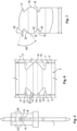
- Figure 7 is a schematic illustration of a cutout of the conductor 1.
- the grooves 17, 18 are arranged parallel with the transverse extent of the webs 15, 16.
- the grooves 17, 18 have differently inclined first and second groove faces 22, 23 perpendicularly relative to the webs 15, 16.
- the opening angle of the groove faces 22, 23 may be in a range between 50 and 80 degrees, for example, 65 degrees.
- the first groove face 22 which faces the respective web 15, 16 has a smaller inclination than the second groove face 23 with respect to a longitudinal axis of the conductor 1. In this manner, both improved filling of the groove is achieved and more robust sealing is enabled.
- the grooves may have groove faces which are arranged at different cross-sections, for example, symmetrically.
- sealing material it is possible to use, for example, liquid adhesive or hot-melt adhesive.
- the angle of inclination of the second groove face 23 is in the range between 90° and 130° with respect to a line perpendicular to the upper side 6.
- the angle of inclination of the first groove face 22 may be between 150° and 100° with respect to a line perpendicular to the upper side 6.
- the webs 15, 16 preferably have in a sealing region, which abuts the housing 2, a rounded contour in cross-section perpendicularly relative to the longitudinal extent of the respective web 15, 16. Reliable and robust sealing with respect to the housing is thereby achieved.
- the webs 15, 16 protrude by, for example, from 1% to 15% of the thickness of the conductor from the upper side 6 or lower side 7.
Landscapes
- Connector Housings Or Holding Contact Members (AREA)
- Switch Cases, Indication, And Locking (AREA)
Description
- The invention relates to an electrical contact according to
patent claim 1. - In the prior art, there are known electrical contacts in which an electrical conductor is inserted into a plastics housing. An object of the invention is to provide an improved electrical contact.
-
US 5 873 752 discloses a tow socket connector having sealant, wherein the tow socket connector is provided for receiving a plug form a towed vehicle and having multiple electrical terminals sealed actually through the socket from one side to the other. Each terminal is locked in its associated opening in the connector by a snap member and the thickness of each terminal is expanded by jogs formed along a portion of its length to provide a slight fit and a sealant block between the terminal and its opening. Each terminal includes a horizontal opening to permit the flow of sealant in a well formed at the upper hand of the socket. -
JP H03 30387 U -
JP 3 3651338 B1 JP H09 147968 A -
WO 2008/075802 A1 discloses an electronic part with an external appearance defined by a case. The case is formed with a through-hole for allowing an internal space of the case to communicate with the outside, and a terminal is installed through the through-hole. The terminal electrically connects devices within the case with the outside. The case may be manufactured from a plurality of pieces. Sealants are applied to a gap between the through-hole of the case and the terminal and around the through-hole and also two portions, where the plurality of pieces of the case are combined together. -
US 5,885,114 discloses a connector for automatic transmission. The connector comprises a housing with a plurality of cavities for receiving terminals. The cavities are separated from one another in such a manner that the cavities communicate with one another through partially notched wall portions. The housing has terminal passage holes into which the terminals are press-fitted. A rear side of the housing is filled with resin material. -
US 5,000,695 discloses a female connector with a holder that serves to hold a female terminal. The holder is made of resin or rubber having elasticity. The holder comprises at an outer peripheral surface two circumferentially extending parallel raised portions defining a recessed portion in between. The raised portions contact an inner wall of a case in which the holder is arranged. Adjacent to the holder, a sealing member is arranged within the case. -
EP 0 574 862 A2 discloses a sealed electrical connector with a housing, wherein a cable is arranged within the housing. Between the cable and the housing, a sealing member is arranged. Furthermore, an insert seal is arranged adjacent to the sealing member. - The object of the invention is achieved by the electrical contact according to
patent claim 1. - Other advantageous embodiments of the invention are set out in the dependent claims.
- An advantage of the electrical contact described is that sealing material which is provided to seal an intermediate space between the electrical conductor and the housing is securely retained in a fixed region of the housing. This is achieved by the electrical conductor having a web which is arranged transversely relative to a longitudinal direction of the conductor and which protrudes by a predetermined height above a side face of the electrical conductor. Consequently, in the assembled state of the conductor, the web abuts the housing so that a flow blocking member for the sealing material is produced by means of the web. Owing to the formation of the web, on the one hand, a flow blocking member is produced and, on the other hand, owing to the free space between the conductor and the housing, simple and reliable assembly of the conductor in the housing is possible. In addition, the sealing material can be introduced into the free space, that is to say, in the intermediate space between the conductor and the housing.
- The web protrudes to such an extent beyond the lateral face of the conductor that the web abuts a wall of the housing in a sealing manner.
- The conductor has four lateral faces, a web being arranged on each of the four lateral faces, respectively. In this manner, it is possible to apply sealing material to four lateral faces of the conductor, without the sealing material being able to flow into inadmissible regions. Owing to the formation of the webs on the lateral faces of the conductor, a sealing of the intermediate space in the conducting housing is possible at all four lateral faces of the conductor, without the sealing material being able to flow beyond the regions delimited by the webs. Consequently, reliable and fluid-tight embedding of the conductor in the housing is enabled.
- In another embodiment, two identical webs are formed at two opposing lateral faces, respectively, the two types of web being constructed differently. In this manner, the type of webs can be adapted to the width of the lateral face. Tests have shown that webs which protrude to a relatively large extent beyond the lateral face on narrow lateral faces are hardly disadvantageous for the assembly and the function of the electrical contact. Consequently, on the narrow lateral faces, webs which protrude further from the lateral face can be provided. Furthermore, tests have shown that the webs on the wider lateral faces are not intended to extend too far beyond the lateral face of the conductor since assembly is otherwise made more difficult. The webs preferably protrude on the wider lateral faces to such an extent beyond the lateral faces that the webs in the assembled state of the conductor touch the associated inner walls of the housing. Depending on the embodiment selected, in the assembled state there may also be a small spacing between the webs of the wide lateral faces and the associated housing walls. Depending on the viscosity of the sealing material, in spite of the spacing of the web from the lateral wall of the housing, the sealing material is prevented from flowing past the web.
- In another embodiment, the conductor has a groove parallel with the construction of the web. The combination of the web and groove forms an improved flow resistance for the sealing material. In addition, owing to the formation of the groove at the side of the web in the sealing region, that is to say, on the web, a particularly thick layer of sealing material is introduced. Consequently, improved sealing is achieved which in particular ensures improved sealing against impediments such as impacts, temperature fluctuations, deviations from standard geometries.
- In another embodiment, an electrical conductor has a groove at both sides of the web.
- In another embodiment, the groove has two lateral faces, the lateral faces being arranged substantially parallel with the longitudinal extent of the web, that is to say, transversely relative to the longitudinal direction of the conductor. The two lateral faces of the groove have different inclinations relative to the lateral face of the conductor. The lateral face of the groove which is adjacent to the web has a shallower inclination than the lateral face directed away from the web. In this manner, improved influx and filling of the groove with sealing material are enabled. In addition, the sealing is improved by the special configuration of the lateral faces of the groove.
- In another embodiment, the flatter lateral face of the groove has a larger width than the steeper lateral face of the groove.
- In another embodiment, the two lateral faces of the groove have an opening angle between 50° and 80°, for example 65°, in a direction perpendicular relative to the groove. This opening angle of the groove leads, on the one hand, to good filling of the groove with sealing material and, on the other hand, to reliable and robust sealing of the intermediate space between the conductor and the housing.
- The invention is explained in greater detail with reference to the Figures, in which:
-
Figure 1 shows a housing and an electrical conductor prior to the assembly, -
Figure 2 is an enlarged illustration of a portion of the conductor, -
Figure 3 is a cutout of the conductor ofFigure 2 , -
Figure 4 is a cross-sectional illustration of the electrical contact, -
Figure 5 is a second cross-sectional illustration of the electrical contact, -
Figure 6 is an enlarged partial cutout ofFigure 5 , and -
Figure 7 is an enlarged cross-section through the electrical conductor. -
Figure 1 is a perspective view of anelectrical conductor 1 and ahousing 2, thehousing 2 having arecess 3 for receiving theelectrical conductor 1. Thehousing 2 is, for example, formed from a plastics material. Theelectrical conductor 1 is, for example, produced as a punched component from a metal sheet and has a contact tongue 4 at a first end andcontact pins 5 at the opposing second end. In the embodiment illustrated, theconductor 1 is of a rectangular cross-section. In addition, theconductor 1 is of an elongate strip form, two wide lateral faces, that is to say, anupper side 6 and alower side 7, being opposite each other in a parallel manner. At the sides of the upper side and thelower side - The
webs grooves conductor 1 by means of a pressing operation. -
Figure 2 is an enlarged view of the conductor. - The width of the contact tongue 4 is constant as far as the central region of the
conductor 1. In a central region of theconductor 1, the lateral faces 8, 9 have afirst recess 10. In the direction towards the contact pins 5, there follows with a fixed spacing relative to the first recess 10 asecond recess 11 in the lateral faces 8, 9. Adjacent to thesecond recess 11, there follow twocatch projections second catch projection 13, with spacing in the direction towards the contact pins 5, there follows athird catch projection 14 which is also formed on the first and secondlateral face 8, 9. The first and thesecond catch projections conductor 1 in thehousing 2. The first and second lateral faces 8, 9 are constructed in an identical manner. At the height of thethird catch projection 14, aweb lower side third catch projections 14 of the two lateral faces 8, 9 and the first andsecond webs lower side conductor 1. -
Figure 3 is an enlarged view of the cutout of theconductor 1 in the region of thewebs third catch projections 14. In the embodiment illustrated, a first or asecond groove web upper side 6 and in thelower side 7. -
Figure 4 is a cross-section through anelectrical contact 19, in which theconductor 1 is mounted in thehousing 2 and sealingmaterial 21 is further introduced into thehousing 2 in aportion 20 of therecess 3. The sealingmaterial 21, owing to thewebs third catch projections 14, can flow only as far as thewebs upper portion 20 of therecess 3 is filled with sealingmaterial 21. - In
Figure 4 , the engagement of thecatch projections recess 3 of thehousing 2 can clearly be seen. -
Figure 5 is another cross-section through the arrangement ofFigure 4 . It can clearly be seen that thewebs recess 3 of thehousing 2. -
Figure 6 is an enlarged illustration of the region of thewebs Figure 5 . In this instance, the protrusion of thewebs upper side 6 andlower side 7 of theconductor 1 can clearly be seen, respectively. -
Figure 7 is a schematic illustration of a cutout of theconductor 1. - With reference to
Figure 7 , it can be seen that thegrooves webs grooves webs first groove face 22 which faces therespective web second groove face 23 with respect to a longitudinal axis of theconductor 1. In this manner, both improved filling of the groove is achieved and more robust sealing is enabled. - Depending on the embodiment selected, it is also possible to dispense with the
grooves - As a sealing material, it is possible to use, for example, liquid adhesive or hot-melt adhesive.
- In addition, instead of the two
contact pins 5, only one contact pin or another shape of the contact may also be provided. - The angle of inclination of the
second groove face 23 is in the range between 90° and 130° with respect to a line perpendicular to theupper side 6. In addition, the angle of inclination of thefirst groove face 22 may be between 150° and 100° with respect to a line perpendicular to theupper side 6. - The
webs housing 2, a rounded contour in cross-section perpendicularly relative to the longitudinal extent of therespective web - The
webs upper side 6 orlower side 7.
Claims (9)
- Electrical contact (19) having a housing (2) in which an electrical conductor (1) is embedded, wherein the housing (2) has a recess (3), the electrical conductor (1) being inserted into the recess (3), an intermediate space (20) between the conductor (1) and the housing (2) being filled with a sealing material (21), the conductor (1) extending in the longitudinal direction through the housing (2), wherein the conductor (1) has four lateral faces (6, 7, 8, 9), characterized by
a web (15, 16) being arranged on the four lateral faces (6, 7, 8, 9), respectively , the webs (15, 16) extending on the lateral faces (6, 7, 8, 9) and transversely relative to a longitudinal direction of the conductor (1), the webs (15, 16) protruding from the respective lateral face (6, 7, 8, 9) of the conductor (1) by a predetermined height beyond the sides (6, 7, 8, 9) of the conductor (1), wherein the webs (15, 16) abut associated lateral walls of the recess (3) of the housing (2), the sealing material (21) being arranged at one side of the webs (15, 16). - Electrical contact according to claim 1, wherein two opposing lateral faces (6, 7, 8, 9) are arranged parallel with each other, the webs (15, 16, 14) of opposing lateral faces being constructed in an identical manner.
- Electrical contact according to claim 2, wherein the webs of the two narrower lateral faces (8, 9) protrude further from the lateral face than the webs (15, 16) of the wider lateral faces (6, 7).
- Electrical contact according to any one of the preceding claims, wherein the web (15, 16) has a groove (17, 18) at least at one side, the groove (17, 18) being constructed parallel with the web.
- Electrical contact according to claim 4, wherein a groove (17, 18) is arranged at two sides of the web (15, 16), respectively.
- Electrical contact according to any one of claims 1 to 5, wherein the web (15, 16) protrudes beyond the lateral face (6, 7) in the range from 1% to 10% of a thickness of the conductor (1).
- Electrical contact according to any one of claims 4 to 6, wherein the groove (17, 18) has two lateral faces (22, 23), the lateral faces (22, 23) being arranged transversely relative to the longitudinal direction of the conductor (1), the lateral faces having different inclinations, the lateral face (22) which is associated with the web (15, 16) having a shallower inclination than the opposing lateral face (23).
- Electrical contact according to claim 7, wherein the flatter lateral face (22) has a larger width than the steeper lateral face (23).
- Electrical contact according to any one of claims 4 to 8, wherein lateral faces of the groove have an opening angle between 50° and 80°, for example 65°, in a plane perpendicular relative to the groove.
Applications Claiming Priority (2)
| Application Number | Priority Date | Filing Date | Title |
|---|---|---|---|
| DE201210206035 DE102012206035A1 (en) | 2012-04-13 | 2012-04-13 | Electrical contact with sealing bar |
| PCT/EP2013/057322 WO2013153038A1 (en) | 2012-04-13 | 2013-04-08 | Electrical contact with sealing web |
Publications (2)
| Publication Number | Publication Date |
|---|---|
| EP2845271A1 EP2845271A1 (en) | 2015-03-11 |
| EP2845271B1 true EP2845271B1 (en) | 2023-03-29 |
Family
ID=48050041
Family Applications (1)
| Application Number | Title | Priority Date | Filing Date |
|---|---|---|---|
| EP13714661.9A Active EP2845271B1 (en) | 2012-04-13 | 2013-04-08 | Electrical contact with sealing web |
Country Status (6)
| Country | Link |
|---|---|
| US (1) | US9490565B2 (en) |
| EP (1) | EP2845271B1 (en) |
| JP (1) | JP6143384B2 (en) |
| CN (1) | CN104247161B (en) |
| DE (1) | DE102012206035A1 (en) |
| WO (1) | WO2013153038A1 (en) |
Families Citing this family (5)
| Publication number | Priority date | Publication date | Assignee | Title |
|---|---|---|---|---|
| JP6716941B2 (en) * | 2016-02-18 | 2020-07-01 | 株式会社オートネットワーク技術研究所 | Terminal block and manufacturing method thereof |
| EP3567679B1 (en) * | 2018-05-09 | 2021-09-29 | Tyco Electronics Belgium EC bvba | Sealed electrical connection between a first conductor and a second conductor and corresponding production method |
| DE102018113980A1 (en) * | 2018-06-12 | 2019-12-12 | Te Connectivity Germany Gmbh | Method for producing an electrical connector, in particular electrical connector for a high-density header system; and electrical connectors, in particular electrical connectors for the automotive sector; and a high-density header system |
| JP7253354B2 (en) | 2018-10-31 | 2023-04-06 | モレックス エルエルシー | connector |
| JP7388706B2 (en) * | 2020-02-21 | 2023-11-29 | 日本圧着端子製造株式会社 | Square wire terminals, connectors, methods for manufacturing square wire terminals, and methods for manufacturing connectors |
Citations (6)
| Publication number | Priority date | Publication date | Assignee | Title |
|---|---|---|---|---|
| JPH0330387U (en) * | 1989-08-02 | 1991-03-26 | ||
| JPH08250193A (en) * | 1995-03-09 | 1996-09-27 | Sumitomo Wiring Syst Ltd | Connector and its manufacture |
| JPH09147968A (en) * | 1995-11-21 | 1997-06-06 | Sumitomo Wiring Syst Ltd | Seal structure of terminal metal fitting |
| US5873752A (en) * | 1997-12-08 | 1999-02-23 | Joseph Pollak Corporation | Tow socket connector having sealant |
| US20070184701A1 (en) * | 2006-02-03 | 2007-08-09 | Yazaki Corporation | Structure for attaching gasket |
| DE102009058525A1 (en) * | 2009-12-16 | 2011-06-22 | KOSTAL Kontakt Systeme GmbH, 58513 | Fluid-tight contact pin feedthrough |
Family Cites Families (10)
| Publication number | Priority date | Publication date | Assignee | Title |
|---|---|---|---|---|
| US5000695A (en) * | 1987-07-20 | 1991-03-19 | Murata Manufacturing Co., Ltd. | Females connector construction for use in high voltage circuits |
| US5017160A (en) * | 1990-03-28 | 1991-05-21 | W. L. Gore & Associates, Inc. | Replaceable seal for electrical cables in a severe environment |
| US5178547A (en) * | 1991-09-13 | 1993-01-12 | Trw Inc. | Initiator assembly with connector interface element |
| GB9212732D0 (en) * | 1992-06-16 | 1992-07-29 | Amp Gmbh | Sealed electrical connector and method of making the same |
| JPH09106854A (en) * | 1995-10-13 | 1997-04-22 | Yazaki Corp | Female terminal for waterproof connector and resin-filled waterproof connector |
| JP3440711B2 (en) * | 1996-08-26 | 2003-08-25 | 矢崎総業株式会社 | Automatic transmission connector and method of assembling the same |
| US6073963A (en) * | 1998-03-19 | 2000-06-13 | Oea, Inc. | Initiator with injection molded insert member |
| JP2000077125A (en) * | 1998-08-28 | 2000-03-14 | Kel Corp | Male and female mating connectors |
| BRPI0621973A2 (en) * | 2006-12-18 | 2014-04-29 | Lg Electronics Inc | ELECTRONIC COMPONENTS |
| JP2011521429A (en) * | 2008-05-19 | 2011-07-21 | エマーソン エレクトリック カンパニー | Power terminal feedthrough |
-
2012
- 2012-04-13 DE DE201210206035 patent/DE102012206035A1/en not_active Ceased
-
2013
- 2013-04-08 CN CN201380019704.7A patent/CN104247161B/en not_active Expired - Fee Related
- 2013-04-08 WO PCT/EP2013/057322 patent/WO2013153038A1/en not_active Ceased
- 2013-04-08 US US14/394,096 patent/US9490565B2/en not_active Expired - Fee Related
- 2013-04-08 JP JP2015504920A patent/JP6143384B2/en not_active Expired - Fee Related
- 2013-04-08 EP EP13714661.9A patent/EP2845271B1/en active Active
Patent Citations (7)
| Publication number | Priority date | Publication date | Assignee | Title |
|---|---|---|---|---|
| JPH0330387U (en) * | 1989-08-02 | 1991-03-26 | ||
| JPH08250193A (en) * | 1995-03-09 | 1996-09-27 | Sumitomo Wiring Syst Ltd | Connector and its manufacture |
| JP3365138B2 (en) * | 1995-03-09 | 2003-01-08 | 住友電装株式会社 | Connector and manufacturing method thereof |
| JPH09147968A (en) * | 1995-11-21 | 1997-06-06 | Sumitomo Wiring Syst Ltd | Seal structure of terminal metal fitting |
| US5873752A (en) * | 1997-12-08 | 1999-02-23 | Joseph Pollak Corporation | Tow socket connector having sealant |
| US20070184701A1 (en) * | 2006-02-03 | 2007-08-09 | Yazaki Corporation | Structure for attaching gasket |
| DE102009058525A1 (en) * | 2009-12-16 | 2011-06-22 | KOSTAL Kontakt Systeme GmbH, 58513 | Fluid-tight contact pin feedthrough |
Also Published As
| Publication number | Publication date |
|---|---|
| US20150118903A1 (en) | 2015-04-30 |
| WO2013153038A1 (en) | 2013-10-17 |
| EP2845271A1 (en) | 2015-03-11 |
| CN104247161A (en) | 2014-12-24 |
| DE102012206035A8 (en) | 2014-01-09 |
| JP6143384B2 (en) | 2017-06-07 |
| DE102012206035A1 (en) | 2013-10-17 |
| JP2015513203A (en) | 2015-04-30 |
| CN104247161B (en) | 2017-06-13 |
| US9490565B2 (en) | 2016-11-08 |
Similar Documents
| Publication | Publication Date | Title |
|---|---|---|
| EP2056412B1 (en) | Electrical connector | |
| JP5369125B2 (en) | Electrical connector | |
| CN102403595B (en) | Electrical connector | |
| US7845987B2 (en) | Electrical connector with plug connector and receptacle connector | |
| US8075345B2 (en) | Electrical connector | |
| CN117595020A (en) | Plug connector for an electrical plug connection and electrical plug connection formed therefrom | |
| KR20170004840A (en) | Board-to-board connector assembly and connector | |
| JP2008300193A (en) | connector | |
| US8764470B2 (en) | Board to board connector with enhanced metal locking features | |
| EP3232515B1 (en) | Contact element and contact device having such a contact element | |
| EP2369692A1 (en) | Shield case, connector and electronic equipment | |
| US11228139B2 (en) | Plug connector of an electrical plug connection and set comprising a plug connector and functional element | |
| CN101473494A (en) | Sealed electric connector | |
| KR20130124353A (en) | Contact and connector with contacts | |
| CN104247161B (en) | Electrical contact with sealing web | |
| TW201230508A (en) | Connector and header used in same | |
| CN102403592B (en) | Electrical connector | |
| JP5665585B2 (en) | Electrical connector | |
| EP1955411A1 (en) | Electrical connector | |
| TWI539685B (en) | Kontaktierungsstecker zur direktkontaktierung einer leiterplatte | |
| US20090298345A1 (en) | Connector | |
| KR20130022229A (en) | Connector assembly | |
| JP2014011092A (en) | Connector structure | |
| JP2008117706A (en) | Card edge connector | |
| KR101758674B1 (en) | misassembling preventing apparatus for connector assembly |
Legal Events
| Date | Code | Title | Description |
|---|---|---|---|
| PUAI | Public reference made under article 153(3) epc to a published international application that has entered the european phase |
Free format text: ORIGINAL CODE: 0009012 |
|
| 17P | Request for examination filed |
Effective date: 20141118 |
|
| AK | Designated contracting states |
Kind code of ref document: A1 Designated state(s): AL AT BE BG CH CY CZ DE DK EE ES FI FR GB GR HR HU IE IS IT LI LT LU LV MC MK MT NL NO PL PT RO RS SE SI SK SM TR |
|
| AX | Request for extension of the european patent |
Extension state: BA ME |
|
| DAX | Request for extension of the european patent (deleted) | ||
| RAP1 | Party data changed (applicant data changed or rights of an application transferred) |
Owner name: TE CONNECTIVITY GERMANY GMBH |
|
| STAA | Information on the status of an ep patent application or granted ep patent |
Free format text: STATUS: EXAMINATION IS IN PROGRESS |
|
| 17Q | First examination report despatched |
Effective date: 20161104 |
|
| GRAP | Despatch of communication of intention to grant a patent |
Free format text: ORIGINAL CODE: EPIDOSNIGR1 |
|
| STAA | Information on the status of an ep patent application or granted ep patent |
Free format text: STATUS: GRANT OF PATENT IS INTENDED |
|
| INTG | Intention to grant announced |
Effective date: 20221012 |
|
| GRAS | Grant fee paid |
Free format text: ORIGINAL CODE: EPIDOSNIGR3 |
|
| GRAA | (expected) grant |
Free format text: ORIGINAL CODE: 0009210 |
|
| STAA | Information on the status of an ep patent application or granted ep patent |
Free format text: STATUS: THE PATENT HAS BEEN GRANTED |
|
| AK | Designated contracting states |
Kind code of ref document: B1 Designated state(s): AL AT BE BG CH CY CZ DE DK EE ES FI FR GB GR HR HU IE IS IT LI LT LU LV MC MK MT NL NO PL PT RO RS SE SI SK SM TR |
|
| REG | Reference to a national code |
Ref country code: GB Ref legal event code: FG4D |
|
| REG | Reference to a national code |
Ref country code: CH Ref legal event code: EP |
|
| REG | Reference to a national code |
Ref country code: DE Ref legal event code: R096 Ref document number: 602013083513 Country of ref document: DE |
|
| REG | Reference to a national code |
Ref country code: AT Ref legal event code: REF Ref document number: 1557331 Country of ref document: AT Kind code of ref document: T Effective date: 20230415 |
|
| REG | Reference to a national code |
Ref country code: IE Ref legal event code: FG4D |
|
| REG | Reference to a national code |
Ref country code: LT Ref legal event code: MG9D |
|
| PG25 | Lapsed in a contracting state [announced via postgrant information from national office to epo] |
Ref country code: RS Free format text: LAPSE BECAUSE OF FAILURE TO SUBMIT A TRANSLATION OF THE DESCRIPTION OR TO PAY THE FEE WITHIN THE PRESCRIBED TIME-LIMIT Effective date: 20230329 Ref country code: NO Free format text: LAPSE BECAUSE OF FAILURE TO SUBMIT A TRANSLATION OF THE DESCRIPTION OR TO PAY THE FEE WITHIN THE PRESCRIBED TIME-LIMIT Effective date: 20230629 Ref country code: LV Free format text: LAPSE BECAUSE OF FAILURE TO SUBMIT A TRANSLATION OF THE DESCRIPTION OR TO PAY THE FEE WITHIN THE PRESCRIBED TIME-LIMIT Effective date: 20230329 Ref country code: LT Free format text: LAPSE BECAUSE OF FAILURE TO SUBMIT A TRANSLATION OF THE DESCRIPTION OR TO PAY THE FEE WITHIN THE PRESCRIBED TIME-LIMIT Effective date: 20230329 Ref country code: HR Free format text: LAPSE BECAUSE OF FAILURE TO SUBMIT A TRANSLATION OF THE DESCRIPTION OR TO PAY THE FEE WITHIN THE PRESCRIBED TIME-LIMIT Effective date: 20230329 |
|
| REG | Reference to a national code |
Ref country code: NL Ref legal event code: MP Effective date: 20230329 |
|
| REG | Reference to a national code |
Ref country code: AT Ref legal event code: MK05 Ref document number: 1557331 Country of ref document: AT Kind code of ref document: T Effective date: 20230329 |
|
| PG25 | Lapsed in a contracting state [announced via postgrant information from national office to epo] |
Ref country code: SE Free format text: LAPSE BECAUSE OF FAILURE TO SUBMIT A TRANSLATION OF THE DESCRIPTION OR TO PAY THE FEE WITHIN THE PRESCRIBED TIME-LIMIT Effective date: 20230329 Ref country code: NL Free format text: LAPSE BECAUSE OF FAILURE TO SUBMIT A TRANSLATION OF THE DESCRIPTION OR TO PAY THE FEE WITHIN THE PRESCRIBED TIME-LIMIT Effective date: 20230329 Ref country code: GR Free format text: LAPSE BECAUSE OF FAILURE TO SUBMIT A TRANSLATION OF THE DESCRIPTION OR TO PAY THE FEE WITHIN THE PRESCRIBED TIME-LIMIT Effective date: 20230630 Ref country code: FI Free format text: LAPSE BECAUSE OF FAILURE TO SUBMIT A TRANSLATION OF THE DESCRIPTION OR TO PAY THE FEE WITHIN THE PRESCRIBED TIME-LIMIT Effective date: 20230329 |
|
| PG25 | Lapsed in a contracting state [announced via postgrant information from national office to epo] |
Ref country code: SM Free format text: LAPSE BECAUSE OF FAILURE TO SUBMIT A TRANSLATION OF THE DESCRIPTION OR TO PAY THE FEE WITHIN THE PRESCRIBED TIME-LIMIT Effective date: 20230329 Ref country code: RO Free format text: LAPSE BECAUSE OF FAILURE TO SUBMIT A TRANSLATION OF THE DESCRIPTION OR TO PAY THE FEE WITHIN THE PRESCRIBED TIME-LIMIT Effective date: 20230329 Ref country code: PT Free format text: LAPSE BECAUSE OF FAILURE TO SUBMIT A TRANSLATION OF THE DESCRIPTION OR TO PAY THE FEE WITHIN THE PRESCRIBED TIME-LIMIT Effective date: 20230731 Ref country code: ES Free format text: LAPSE BECAUSE OF FAILURE TO SUBMIT A TRANSLATION OF THE DESCRIPTION OR TO PAY THE FEE WITHIN THE PRESCRIBED TIME-LIMIT Effective date: 20230329 Ref country code: EE Free format text: LAPSE BECAUSE OF FAILURE TO SUBMIT A TRANSLATION OF THE DESCRIPTION OR TO PAY THE FEE WITHIN THE PRESCRIBED TIME-LIMIT Effective date: 20230329 Ref country code: AT Free format text: LAPSE BECAUSE OF FAILURE TO SUBMIT A TRANSLATION OF THE DESCRIPTION OR TO PAY THE FEE WITHIN THE PRESCRIBED TIME-LIMIT Effective date: 20230329 |
|
| PG25 | Lapsed in a contracting state [announced via postgrant information from national office to epo] |
Ref country code: SK Free format text: LAPSE BECAUSE OF FAILURE TO SUBMIT A TRANSLATION OF THE DESCRIPTION OR TO PAY THE FEE WITHIN THE PRESCRIBED TIME-LIMIT Effective date: 20230329 Ref country code: PL Free format text: LAPSE BECAUSE OF FAILURE TO SUBMIT A TRANSLATION OF THE DESCRIPTION OR TO PAY THE FEE WITHIN THE PRESCRIBED TIME-LIMIT Effective date: 20230329 Ref country code: IS Free format text: LAPSE BECAUSE OF FAILURE TO SUBMIT A TRANSLATION OF THE DESCRIPTION OR TO PAY THE FEE WITHIN THE PRESCRIBED TIME-LIMIT Effective date: 20230729 |
|
| REG | Reference to a national code |
Ref country code: CH Ref legal event code: PL |
|
| PG25 | Lapsed in a contracting state [announced via postgrant information from national office to epo] |
Ref country code: LU Free format text: LAPSE BECAUSE OF NON-PAYMENT OF DUE FEES Effective date: 20230408 |
|
| REG | Reference to a national code |
Ref country code: DE Ref legal event code: R097 Ref document number: 602013083513 Country of ref document: DE |
|
| REG | Reference to a national code |
Ref country code: BE Ref legal event code: MM Effective date: 20230430 |
|
| PG25 | Lapsed in a contracting state [announced via postgrant information from national office to epo] |
Ref country code: MC Free format text: LAPSE BECAUSE OF FAILURE TO SUBMIT A TRANSLATION OF THE DESCRIPTION OR TO PAY THE FEE WITHIN THE PRESCRIBED TIME-LIMIT Effective date: 20230329 |
|
| PG25 | Lapsed in a contracting state [announced via postgrant information from national office to epo] |
Ref country code: MC Free format text: LAPSE BECAUSE OF FAILURE TO SUBMIT A TRANSLATION OF THE DESCRIPTION OR TO PAY THE FEE WITHIN THE PRESCRIBED TIME-LIMIT Effective date: 20230329 Ref country code: LI Free format text: LAPSE BECAUSE OF NON-PAYMENT OF DUE FEES Effective date: 20230430 Ref country code: DK Free format text: LAPSE BECAUSE OF FAILURE TO SUBMIT A TRANSLATION OF THE DESCRIPTION OR TO PAY THE FEE WITHIN THE PRESCRIBED TIME-LIMIT Effective date: 20230329 Ref country code: CZ Free format text: LAPSE BECAUSE OF FAILURE TO SUBMIT A TRANSLATION OF THE DESCRIPTION OR TO PAY THE FEE WITHIN THE PRESCRIBED TIME-LIMIT Effective date: 20230329 Ref country code: CH Free format text: LAPSE BECAUSE OF NON-PAYMENT OF DUE FEES Effective date: 20230430 |
|
| PLBE | No opposition filed within time limit |
Free format text: ORIGINAL CODE: 0009261 |
|
| STAA | Information on the status of an ep patent application or granted ep patent |
Free format text: STATUS: NO OPPOSITION FILED WITHIN TIME LIMIT |
|
| REG | Reference to a national code |
Ref country code: IE Ref legal event code: MM4A |
|
| GBPC | Gb: european patent ceased through non-payment of renewal fee |
Effective date: 20230629 |
|
| PG25 | Lapsed in a contracting state [announced via postgrant information from national office to epo] |
Ref country code: BE Free format text: LAPSE BECAUSE OF NON-PAYMENT OF DUE FEES Effective date: 20230430 |
|
| 26N | No opposition filed |
Effective date: 20240103 |
|
| PG25 | Lapsed in a contracting state [announced via postgrant information from national office to epo] |
Ref country code: IE Free format text: LAPSE BECAUSE OF NON-PAYMENT OF DUE FEES Effective date: 20230408 |
|
| PG25 | Lapsed in a contracting state [announced via postgrant information from national office to epo] |
Ref country code: IE Free format text: LAPSE BECAUSE OF NON-PAYMENT OF DUE FEES Effective date: 20230408 Ref country code: GB Free format text: LAPSE BECAUSE OF NON-PAYMENT OF DUE FEES Effective date: 20230629 |
|
| PG25 | Lapsed in a contracting state [announced via postgrant information from national office to epo] |
Ref country code: SI Free format text: LAPSE BECAUSE OF FAILURE TO SUBMIT A TRANSLATION OF THE DESCRIPTION OR TO PAY THE FEE WITHIN THE PRESCRIBED TIME-LIMIT Effective date: 20230329 |
|
| PG25 | Lapsed in a contracting state [announced via postgrant information from national office to epo] |
Ref country code: SI Free format text: LAPSE BECAUSE OF FAILURE TO SUBMIT A TRANSLATION OF THE DESCRIPTION OR TO PAY THE FEE WITHIN THE PRESCRIBED TIME-LIMIT Effective date: 20230329 |
|
| PG25 | Lapsed in a contracting state [announced via postgrant information from national office to epo] |
Ref country code: BG Free format text: LAPSE BECAUSE OF FAILURE TO SUBMIT A TRANSLATION OF THE DESCRIPTION OR TO PAY THE FEE WITHIN THE PRESCRIBED TIME-LIMIT Effective date: 20230329 |
|
| PG25 | Lapsed in a contracting state [announced via postgrant information from national office to epo] |
Ref country code: BG Free format text: LAPSE BECAUSE OF FAILURE TO SUBMIT A TRANSLATION OF THE DESCRIPTION OR TO PAY THE FEE WITHIN THE PRESCRIBED TIME-LIMIT Effective date: 20230329 |
|
| PGFP | Annual fee paid to national office [announced via postgrant information from national office to epo] |
Ref country code: FR Payment date: 20250310 Year of fee payment: 13 |
|
| PGFP | Annual fee paid to national office [announced via postgrant information from national office to epo] |
Ref country code: IT Payment date: 20250320 Year of fee payment: 13 |
|
| PGFP | Annual fee paid to national office [announced via postgrant information from national office to epo] |
Ref country code: DE Payment date: 20250305 Year of fee payment: 13 |
|
| PG25 | Lapsed in a contracting state [announced via postgrant information from national office to epo] |
Ref country code: CY Free format text: LAPSE BECAUSE OF FAILURE TO SUBMIT A TRANSLATION OF THE DESCRIPTION OR TO PAY THE FEE WITHIN THE PRESCRIBED TIME-LIMIT; INVALID AB INITIO Effective date: 20130408 |
|
| PG25 | Lapsed in a contracting state [announced via postgrant information from national office to epo] |
Ref country code: HU Free format text: LAPSE BECAUSE OF FAILURE TO SUBMIT A TRANSLATION OF THE DESCRIPTION OR TO PAY THE FEE WITHIN THE PRESCRIBED TIME-LIMIT; INVALID AB INITIO Effective date: 20130408 |
|
| PG25 | Lapsed in a contracting state [announced via postgrant information from national office to epo] |
Ref country code: TR Free format text: LAPSE BECAUSE OF FAILURE TO SUBMIT A TRANSLATION OF THE DESCRIPTION OR TO PAY THE FEE WITHIN THE PRESCRIBED TIME-LIMIT Effective date: 20230329 |