EP2845192B1 - Tolerance ring with slotted sidewall - Google Patents
Tolerance ring with slotted sidewall Download PDFInfo
- Publication number
- EP2845192B1 EP2845192B1 EP13722513.2A EP13722513A EP2845192B1 EP 2845192 B1 EP2845192 B1 EP 2845192B1 EP 13722513 A EP13722513 A EP 13722513A EP 2845192 B1 EP2845192 B1 EP 2845192B1
- Authority
- EP
- European Patent Office
- Prior art keywords
- wave
- tolerance ring
- ring
- sidewall
- tolerance
- Prior art date
- Legal status (The legal status is an assumption and is not a legal conclusion. Google has not performed a legal analysis and makes no representation as to the accuracy of the status listed.)
- Active
Links
Images





Classifications
-
- F—MECHANICAL ENGINEERING; LIGHTING; HEATING; WEAPONS; BLASTING
- F16—ENGINEERING ELEMENTS AND UNITS; GENERAL MEASURES FOR PRODUCING AND MAINTAINING EFFECTIVE FUNCTIONING OF MACHINES OR INSTALLATIONS; THERMAL INSULATION IN GENERAL
- F16C—SHAFTS; FLEXIBLE SHAFTS; ELEMENTS OR CRANKSHAFT MECHANISMS; ROTARY BODIES OTHER THAN GEARING ELEMENTS; BEARINGS
- F16C11/00—Pivots; Pivotal connections
- F16C11/04—Pivotal connections
-
- F—MECHANICAL ENGINEERING; LIGHTING; HEATING; WEAPONS; BLASTING
- F16—ENGINEERING ELEMENTS AND UNITS; GENERAL MEASURES FOR PRODUCING AND MAINTAINING EFFECTIVE FUNCTIONING OF MACHINES OR INSTALLATIONS; THERMAL INSULATION IN GENERAL
- F16C—SHAFTS; FLEXIBLE SHAFTS; ELEMENTS OR CRANKSHAFT MECHANISMS; ROTARY BODIES OTHER THAN GEARING ELEMENTS; BEARINGS
- F16C27/00—Elastic or yielding bearings or bearing supports, for exclusively rotary movement
- F16C27/02—Sliding-contact bearings
-
- F—MECHANICAL ENGINEERING; LIGHTING; HEATING; WEAPONS; BLASTING
- F16—ENGINEERING ELEMENTS AND UNITS; GENERAL MEASURES FOR PRODUCING AND MAINTAINING EFFECTIVE FUNCTIONING OF MACHINES OR INSTALLATIONS; THERMAL INSULATION IN GENERAL
- F16D—COUPLINGS FOR TRANSMITTING ROTATION; CLUTCHES; BRAKES
- F16D1/00—Couplings for rigidly connecting two coaxial shafts or other movable machine elements
- F16D1/06—Couplings for rigidly connecting two coaxial shafts or other movable machine elements for attachment of a member on a shaft or on a shaft-end
- F16D1/08—Couplings for rigidly connecting two coaxial shafts or other movable machine elements for attachment of a member on a shaft or on a shaft-end with clamping hub; with hub and longitudinal key
- F16D1/0829—Couplings for rigidly connecting two coaxial shafts or other movable machine elements for attachment of a member on a shaft or on a shaft-end with clamping hub; with hub and longitudinal key with radial loading of both hub and shaft by an intermediate ring or sleeve
- F16D1/0835—Couplings for rigidly connecting two coaxial shafts or other movable machine elements for attachment of a member on a shaft or on a shaft-end with clamping hub; with hub and longitudinal key with radial loading of both hub and shaft by an intermediate ring or sleeve due to the elasticity of the ring or sleeve
-
- G—PHYSICS
- G11—INFORMATION STORAGE
- G11B—INFORMATION STORAGE BASED ON RELATIVE MOVEMENT BETWEEN RECORD CARRIER AND TRANSDUCER
- G11B5/00—Recording by magnetisation or demagnetisation of a record carrier; Reproducing by magnetic means; Record carriers therefor
- G11B5/48—Disposition or mounting of heads or head supports relative to record carriers ; arrangements of heads, e.g. for scanning the record carrier to increase the relative speed
- G11B5/4806—Disposition or mounting of heads or head supports relative to record carriers ; arrangements of heads, e.g. for scanning the record carrier to increase the relative speed specially adapted for disk drive assemblies, e.g. assembly prior to operation, hard or flexible disk drives
- G11B5/4813—Mounting or aligning of arm assemblies, e.g. actuator arm supported by bearings, multiple arm assemblies, arm stacks or multiple heads on single arm
-
- G—PHYSICS
- G11—INFORMATION STORAGE
- G11B—INFORMATION STORAGE BASED ON RELATIVE MOVEMENT BETWEEN RECORD CARRIER AND TRANSDUCER
- G11B5/00—Recording by magnetisation or demagnetisation of a record carrier; Reproducing by magnetic means; Record carriers therefor
- G11B5/48—Disposition or mounting of heads or head supports relative to record carriers ; arrangements of heads, e.g. for scanning the record carrier to increase the relative speed
- G11B5/54—Disposition or mounting of heads or head supports relative to record carriers ; arrangements of heads, e.g. for scanning the record carrier to increase the relative speed with provision for moving the head into or out of its operative position or across tracks
- G11B5/55—Track change, selection or acquisition by displacement of the head
- G11B5/5521—Track change, selection or acquisition by displacement of the head across disk tracks
- G11B5/5569—Track change, selection or acquisition by displacement of the head across disk tracks details of specially adapted mobile parts, e.g. electromechanical control devices
-
- F—MECHANICAL ENGINEERING; LIGHTING; HEATING; WEAPONS; BLASTING
- F16—ENGINEERING ELEMENTS AND UNITS; GENERAL MEASURES FOR PRODUCING AND MAINTAINING EFFECTIVE FUNCTIONING OF MACHINES OR INSTALLATIONS; THERMAL INSULATION IN GENERAL
- F16C—SHAFTS; FLEXIBLE SHAFTS; ELEMENTS OR CRANKSHAFT MECHANISMS; ROTARY BODIES OTHER THAN GEARING ELEMENTS; BEARINGS
- F16C2240/00—Specified values or numerical ranges of parameters; Relations between them
- F16C2240/40—Linear dimensions, e.g. length, radius, thickness, gap
-
- F—MECHANICAL ENGINEERING; LIGHTING; HEATING; WEAPONS; BLASTING
- F16—ENGINEERING ELEMENTS AND UNITS; GENERAL MEASURES FOR PRODUCING AND MAINTAINING EFFECTIVE FUNCTIONING OF MACHINES OR INSTALLATIONS; THERMAL INSULATION IN GENERAL
- F16C—SHAFTS; FLEXIBLE SHAFTS; ELEMENTS OR CRANKSHAFT MECHANISMS; ROTARY BODIES OTHER THAN GEARING ELEMENTS; BEARINGS
- F16C2370/00—Apparatus relating to physics, e.g. instruments
- F16C2370/12—Hard disk drives or the like
-
- Y—GENERAL TAGGING OF NEW TECHNOLOGICAL DEVELOPMENTS; GENERAL TAGGING OF CROSS-SECTIONAL TECHNOLOGIES SPANNING OVER SEVERAL SECTIONS OF THE IPC; TECHNICAL SUBJECTS COVERED BY FORMER USPC CROSS-REFERENCE ART COLLECTIONS [XRACs] AND DIGESTS
- Y10—TECHNICAL SUBJECTS COVERED BY FORMER USPC
- Y10T—TECHNICAL SUBJECTS COVERED BY FORMER US CLASSIFICATION
- Y10T403/00—Joints and connections
- Y10T403/32—Articulated members
- Y10T403/32606—Pivoted
-
- Y—GENERAL TAGGING OF NEW TECHNOLOGICAL DEVELOPMENTS; GENERAL TAGGING OF CROSS-SECTIONAL TECHNOLOGIES SPANNING OVER SEVERAL SECTIONS OF THE IPC; TECHNICAL SUBJECTS COVERED BY FORMER USPC CROSS-REFERENCE ART COLLECTIONS [XRACs] AND DIGESTS
- Y10—TECHNICAL SUBJECTS COVERED BY FORMER USPC
- Y10T—TECHNICAL SUBJECTS COVERED BY FORMER US CLASSIFICATION
- Y10T403/00—Joints and connections
- Y10T403/48—Shrunk fit
-
- Y—GENERAL TAGGING OF NEW TECHNOLOGICAL DEVELOPMENTS; GENERAL TAGGING OF CROSS-SECTIONAL TECHNOLOGIES SPANNING OVER SEVERAL SECTIONS OF THE IPC; TECHNICAL SUBJECTS COVERED BY FORMER USPC CROSS-REFERENCE ART COLLECTIONS [XRACs] AND DIGESTS
- Y10—TECHNICAL SUBJECTS COVERED BY FORMER USPC
- Y10T—TECHNICAL SUBJECTS COVERED BY FORMER US CLASSIFICATION
- Y10T403/00—Joints and connections
- Y10T403/70—Interfitted members
- Y10T403/7047—Radially interposed shim or bushing
Definitions
- the present disclosure is directed to tolerance rings, particularly to tolerance rings for actuator arms within hard disk drives.
- This disclosure relates to tolerance ring assemblies, wherein a tolerance ring provides an interference fit between parts of an assembly, in which a first part has a cylindrical portion located in a cylindrical bore of a second part. Further, this disclosure particularly relates to assemblies having a tolerance ring that provides an interference fit between a cylindrical component such as a shaft or a bearing and a housing for the shaft.
- Tolerance rings may be used to provide an interference fit between parts required to transmit torque. Tolerance rings provide a low cost means of providing an interference fit between parts that may not be machined to exact dimensions. Tolerance rings have a number of other potential advantages, such as compensating for different linear coefficients of expansion between the parts, allowing rapid apparatus assembly, and durability.
- a tolerance ring generally comprises a strip of resilient material, for example a metal such as spring steel, the ends of which are brought together to form a ring.
- a band of protrusions extend radially outwards from the ring, or radially inwards towards the center of the ring.
- the protrusions are formations, possibly regular formations, such as corrugations, ridges or waves.
- the protrusions When the ring is located in the annular space between, for example, a shaft and a bore in a housing in which the shaft is located, the protrusions are compressed. Each protrusion acts as a spring and exerts a radial force against the shaft and the surface of the bore, providing an interference fit between the shaft and the housing. Rotation of the housing or the shaft will produce similar rotation in the other of the shaft or the housing, as torque is transmitted by the tolerance ring.
- the band of protrusions is axially flanked by annular regions of the ring that have no formations (known in the art as "unformed regions" of the tolerance ring).
- US 2012/0087044 A1 describes a tolerance ring including a hollow cylindrical body defining a longitudinal axis that passes axially through its center.
- a circumferential gap divides the hollow cylindrical body so that the hollow cylindrical body includes first and second longitudinal edges that define the circumferential gap.
- a plurality of bumps protrudes radially from the hollow cylindrical body, and consists of a plurality of gap-adjacent bumps and a plurality of non-gap-adjacent bumps. At least one of the plurality of bumps is circumferentially between the gap and each of the non-gap-adjacent bumps. None of the plurality of bumps is circumferentially between the gap and each of the gap-adjacent bumps.
- the tolerance ring includes a means for increasing an otherwise lower average radial compressive stiffness of the gap-adjacent bumps to become substantially equal to an average radial stiffness of the non-gap-adjacent bumps.
- tolerance rings usually comprise a strip of resilient material that is curved to allow the easy formation of a ring by overlapping the ends of the strip, a tolerance ring may also be manufactured as an annular band.
- tolerance ring as used hereafter includes both types of tolerance ring.
- shaft as used hereafter includes any assembly component with a cylindrical portion, such as a shaft or a bearing.
- tolerance rings and particularly, to tolerance rings that can be installed within a hard disk drive between a post and a bore formed in an actuator arm.
- a tolerance ring can be fitted around the pivot and then this pivot ring assembly can be inserted into the bore.
- the tolerance ring can be inserted into the bore and the pivot can be inserted into the tolerance ring.
- the waves nearest to the gap tend to be the weakest, i.e., least stiff, since the waves have a gap on one side and material on the other and the remaining waves in the tolerance ring are flanked by material on both sides.
- This variation in stiffness can cause performance variables, e.g., resonance and alignment, to be very dependent on a position of the gap in the hard disk drive assembly. Attempting to optimize the gap location for one performance parameter can adversely affect other performance parameters. This, in turn, can compromise overall performance.
- a tolerance ring according to one or more of the embodiments described herein can include a plurality of slots that extend through the sidewall of the tolerance ring at targeted locations within the unformed sections of the tolerance ring in order to impart controlled weaknesses in the sidewall adjacent to one or more waves.
- a slot can extend along nearly the entire length of the sidewall between two adjacent wave structures to remove nearly all of the unformed section of the sidewall between the wave structures. Removing the unformed section of the sidewall between the wave structures can reduce the stiffness of the adjacent waves since the unformed section provides a strengthening base for the wave structures.
- the slotted tolerance rings disclosed herein can provide a tolerance ring having a resonant frequency and stiffness that do not substantially vary circumferentially around the tolerance ring. As such, the tolerance ring can maintain the post in alignment within the bore and can substantially prevent any rocking of the post within the bore under normal operational loads in nearly any radial direction.
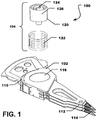
- the hard disk drive assembly 100 can include an actuator arm 102 for a hard disk drive and a pivot assembly 104.
- the actuator arm 102 can include a proximal end 110 and a distal end 112.
- a plurality of read/write heads 114 can extend from the distal end 112 of the actuator arm 102.
- the actuator arm 102 can be formed with a bore 116 near the proximal end 110 of the actuator arm 102.
- FIG. 1 further indicates that the pivot assembly 104 can include a pivot 120 and a tolerance ring 122.
- the pivot 120 can include an inner member 124 and an outer member 126 and the outer member 126 can rotate with respect to the inner member 124.
- the tolerance ring 122 can fit around the pivot 120 and then, the pivot assembly 104 can be installed within the bore 116. In another aspect, the tolerance ring 122 can be placed within the bore 116 and the pivot 120 can be inserted into the tolerance ring 122. The tolerance ring 122 can establish an interference fit between the outer member 126 of the pivot 120 and the bore 116 of the actuator arm 102. As such, the actuator arm 102 can rotate with the outer member 126 of the pivot 120 around the inner member 124 of the pivot 120.
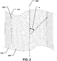
- the tolerance ring 122 can be installed within the bore 116 between an outer component, the actuator arm 102, and an inner component, the pivot 120.
- no portion of the tolerance ring 122 extends beyond the top or bottom of the bore and the tolerance ring 122 can be completely contained within the bore 116.
- a portion of the tolerance ring 122 e.g., a top, a bottom, a structure on a top, a structure on a bottom, or a combination thereof, can extend from the bore.
- the tolerance ring 122 can be configured to engage the inner wall of the bore 116 and the outer wall of the pivot 120 in order to maintain the pivot 120 within the actuator arm 102 in an interference fit.
- the tolerance ring 122 can account for dimensional variations by expanding around the pivot 120 as it is installed thereon and then, at least partially deforming, or compressing, within the bore 116 during installation.
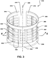
- the tolerance ring 122 can include a generally cylindrical body 302 having a generally cylindrical sidewall 304.
- the sidewall 304 can include a top 306 and a bottom 308.
- the sidewall 304 can include a first end 310 and a second end 312.
- a gap 314 can be established between the first end 310 and the second end 312 of the sidewall 304.
- the gap 314 can extend along the entire length of the body 302 and the gap 314 can establish a split in the body 302.
- the body 302 of the tolerance ring 122 can further include an upper flange 316 extending from the top 306 of the sidewall 304 and a lower flange 318 extending from the bottom 308 of the sidewall 304.
- the tolerance ring 122 can include a central axis 320 and as shown in FIG. 2 and FIG. 3 , in a particular aspect, the flanges 316, 318 can be angled in an outward direction with respect to the central axis 320 of the tolerance ring 122. It is to be understood that the flanges 316, 318 can be angled in an inward direction with respect to the central axis 320. In either case, the flanges 316, 318 can form an angle, ⁇ , with respect the central axis 320. In a particular aspect, ⁇ can be ⁇ 5°, such as ⁇ 10°, or ⁇ 15°. In another aspect, ⁇ can be ⁇ 30°, such as ⁇ 25°, or ⁇ 20°. In another aspect, ⁇ can be within a range between, and including, any of the values disclosed above.
- the tolerance ring 122 may include an overall wall thickness, t OW , that is the distance between the inner surface of the sidewall 304 of the tolerance ring 122 and an outer surface of a wall structure formed in the sidewall 304 of the tolerance ring 122.
- each flange 316, 318 can extend from the sidewall 304 such that each flange 316, 318 has an overall flange thickness, t OF , that is the distance between the inner surface of the sidewall 304 of the tolerance ring 122 and the outer edge of the flange 316, 318.
- t OF can be ⁇ 30% t OW , such as ⁇ 35% t OW , ⁇ 40% t OW , ⁇ 45% t OW , ⁇ 50% t OW , ⁇ 55% t OW , or ⁇ 60% t OW .
- t OF can be ⁇ 98% t OW , such as ⁇ 95% t OW , ⁇ 90% t OW , ⁇ 85% t OW , or ⁇ 80% t OW .
- t OF can be within a range between, and including, any of the percentage values of t OW disclosed above.
- t OW can be measured between an outer surface of the sidewall 304 of the tolerance ring 122 and an inner surface of a wall structure formed in the sidewall 304 of the tolerance ring 122. Further, in such embodiments, t OF is measured between the outer surface of the sidewall 304 of the tolerance ring 122 and the inner edge of the flange 316, 318.
- the tolerance ring 122 can include a plurality of waves 322 formed in the sidewall 304 of the body 302. As illustrated, in one aspect, the waves 322 can extend in an outward direction with respect to the central axis 320. However, in another aspect, the waves 322 can extend in an inward direction with respect to the central axis 320.
- the waves 322 can be formed, or otherwise arranged, in the sidewall 304 of the body 302 so that the tolerance ring 122 includes a plurality of wave structures, such as wave columns 324 that are equally spaced around the circumference of the sidewall 302 of the body 304 of the tolerance ring 122.
- Each wave column 324 can include at least two waves 322 vertically aligned with each other along the sidewall 304 of the body 302 of the tolerance ring 122, e.g., along a length of the tolerance ring 122.
- each wave column 324 of the tolerance ring 122 can have a first wave 330 near the top 306 of the sidewall 304 of the body 302 of the tolerance ring 122 and a second wave 332 near the bottom 308 of the sidewall 304 of the body 302 of the tolerance ring 122.
- the first wave 330 can be centered within the top half of the length of the tolerance ring 122.
- the second wave 332 can be centered within the bottom half of the length of the tolerance ring 122.
- Each wave column 324 can also include a third wave 334 between the first wave 330 and the second wave 332. The third wave 334 can be centered along the length of the tolerance ring 122.
- the first wave 330 can be the same size as the second wave 332, e.g., length, width, height (measured from the outer surface of the sidewall 304).
- the first wave 330, the second wave 332, and the third wave 334 are the same size, e.g., length, width, height (measured from the outer surface of the sidewall 304).
- the first wave 330 and the second wave 332 can have a first length, L 1
- the third wave 334 includes a second length, L 2 , and L 2 ⁇ L 1 .
- L 2 can be ⁇ 75% L 1 , such as L 2 ⁇ 70% L 1 , L 2 ⁇ 65% L 1 , L 2 ⁇ 60% L 1 , L 2 ⁇ 55% L 1 , or L 2 ⁇ 50% L 1 .
- L 2 can be ⁇ 25% L 1 , such as L 2 ⁇ 30% L 1 , L 2 ⁇ 35% L 1 , or L 2 ⁇ 40% L 1 .
- L 2 can be within a range between, and including, any of the percentage values of L 1 disclosed above.
- FIG. 3 , FIG. 4 , and FIG. 5 further indicate that the sidewall 304 of the body 302 of the tolerance ring 122 can include a plurality of unformed sections 340.
- Each unformed section 340 can comprise a section of the sidewall 304 that extends between adjacent wave columns 324 and is not formed with any waves or other structures.
- each unformed section 340 can extend between adjacent wave columns 324 between the upper flange 316 and the lower flange 318 of the body 302 without any additional structure or feature formed between the flanges 316, 318.
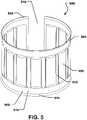
- the wave columns 324 and the unformed sections 340 can alternate around the circumference of the sidewall 304. Moreover, in a particular aspect, the wave columns 324 are evenly spaced around the circumference of the sidewall 304 by the unformed sections 340 of the sidewall 304.
- FIG. 3 and FIG. 5 indicate that the sidewall 304 of the body 302 of the tolerance ring 122 can be formed with a plurality of slots 342 that can extend radially through the sidewall 304 of the body 302.
- the slots 342 can extend along the unformed sections 340 of the sidewall 304.
- the body 302 has a length, L
- the slot has a length, L S .
- L S ⁇ 80% L, such as ⁇ 85% L, or ⁇ 90% L.
- L S ⁇ 99% L, such as ⁇ 98% L, ⁇ 97% L, ⁇ 96% L, ⁇ 95% L.
- L S can be within a range between, and including, any of the percentage of L values described herein.
- each unformed section 340 has a width, W US .
- each slot 342 has a width, W S .
- W S can be ⁇ 50% W US , such as ⁇ 55% Wus, ⁇ 60% W US , ⁇ 65% W US , ⁇ 70% W US , ⁇ 75% W US , ⁇ 80% W US , ⁇ 85% W US , or ⁇ 90% W US .
- W S can be ⁇ 99% W US , such as ⁇ 98% W US , ⁇ 97% W US , ⁇ 96% W US , or ⁇ 95% W US .
- W S can be within a range between, and including, any of the percentage of W US values described above.
- each wave structure has an overall length, L WS .
- L WS can be measured from a top of an upper wave and a bottom of a lower wave.
- L WS can be measured from the top of the elongated wave to the bottom of the elongated wave.
- L S can be ⁇ 50% L WS , such as ⁇ 55% L WS , ⁇ 60% L WS , ⁇ 65% L WS , ⁇ 70% L WS , ⁇ 75% L WS , ⁇ 80% L WS , ⁇ 85% L WS , ⁇ 90% L WS , or ⁇ 95% L WS .
- L S can be ⁇ 110% L WS , such as ⁇ 109% L WS , ⁇ 108% L WS , ⁇ 107% L WS , ⁇ 106% L WS , or ⁇ 105% L WS .
- L S can be within a range between, and including, any of the percentage of L WS values described above.
- each slot 342 can includes a first end and a second end and each end can be rounded. Further, each slot 342 is centered circumferentially and longitudinally within each unformed section 340.
- an unformed section without a slot 342, i.e., a solid unformed section can include a circumferential wave-to-wave force transfer, FT, in which force exerted on one wave structure is transmitted through the solid unformed section to an adjacent wave structure.
- FT circumferential wave-to-wave force transfer
- Removing a portion, or nearly all, of the unformed section can substantially reduce FT and an unformed section 340 having a slot 342 formed therein can have a circumferential wave-to-wave transfer, FT S , which is less than FT.
- FT S can be ⁇ 50% FT, such as ⁇ 45% FT, ⁇ 40% FT, ⁇ 35% FT, ⁇ 30% FT, ⁇ 25% FT, ⁇ 20% FT, ⁇ 15% FT, or ⁇ 10% FT.
- FT S can be ⁇ 1% FT, such as ⁇ 2% FT, ⁇ 3% FT, ⁇ 4% FT, or ⁇ 5% FT.
- FT S can be within a range between, and including, any of the percentage of FT values described above.
- Removing a portion of the unformed section 342 adjacent to a wave 322, or wave structure can alter the stiffness of the adjacent wave 322.
- the stiffness of the adj acent wave can be reduced from an identical wave 322 not adjacent to a slotted unformed section 342.
- a wave adjacent to an unslotted unformed section 342 can include a stiffness, S, and after a slot 342 is cut, punched, or otherwise made, in an unformed section 342 adjacent to the wave 322, the resulting wave can have a stiffness, S S .
- S S can be less than S.
- Ss can be ⁇ 95% S, such as S S ⁇ 90% S, ⁇ 85% S, ⁇ 80% S, ⁇ 75% S, ⁇ 70% S, or ⁇ 65% S.
- S S can be ⁇ 25% S, such as ⁇ 30% S, ⁇ 35% S, ⁇ 40% S, ⁇ 45% S, or ⁇ 50% S.
- S S can be within a range between, and including, any of the percentage of S values described above.
- FIG. 4 indicates that the tolerance ring 122 can include a central axis 350 that can pass through a center 352 of the tolerance ring 122 and bisect the gap 314.
- the tolerance ring 122 can be symmetric about the central axis 350.
- the pivot 120 and the bore 116 can include a central axis that lies along, or nearly along, the central axis 320 of the tolerance ring 122.
- the tolerance ring 122 can provide an axial stiffness that can substantially resist rocking movement of the pivot 120 relative to the bore 116 and the actuator arm 102 in which the central axis of the pivot 120 rotates about an axis perpendicular to the central axis (a longitudinal axis) with respect to the central axis 320.
- the axial stiffness of the tolerance ring 122 can be manipulated to substantially reduce any variations in the axial stiffness caused by the reduction in axial stiffness due to the gap 314. Further, by modifying the unformed sections adjacent to the wave structures, the axial stiffness of the tolerance ring 122 can be manipulated so that the axial stiffness of the tolerance ring 122 does not vary too greatly when measured at various locations circumferentially around the tolerance ring 122.
- the axial stiffness of the tolerance ring 122 through the gap 314, AS G can be measured in a first direction that passes through the gap 314 and a center 360 of the tolerance ring 122.
- the axial stiffness of the tolerance ring 122 perpendicular to the gap 314, AS PG can be measured in a second direction perpendicular to the first direction.
- AS G can be ⁇ 90% AS PG , such as ⁇ 91% AS PG , ⁇ 92% AS PG , ⁇ 93% AS PG , ⁇ 94% AS PG , ⁇ 95% AS PG , or ⁇ 96% AS PG .
- AS G can be ⁇ 100% AS PG , ⁇ 99% AS PG , ⁇ 98% AS PG , or ⁇ 97% AS PG . Moreover, AS G can be within a range between, and including, any of the percentage values of AS PG disclosed above.
- the resonant frequency of the tolerance ring 122 does not vary greatly when measured at various locations circumferentially the assembly in which the tolerance ring 122 is installed.
- the resonant frequency of the tolerance ring 122 through the gap 314, RF G can be measured in a first direction that passes through the gap 314 and the center 360 of the tolerance ring 122.
- the resonant frequency of the tolerance ring 122 perpendicular to the gap 314, RF PG can be measured in a second direction perpendicular to the first direction.
- RF G can be ⁇ 90% RF PG , such as ⁇ 91% RF PG , ⁇ 92% RF PG , ⁇ 93% RF PG , ⁇ 94% RF PG , or ⁇ 95% RF PG . Further, RF G can be ⁇ 100% RF PG , ⁇ 99% RF PG , ⁇ 98% RF PG , ⁇ 97% RF PG , or ⁇ 96% RF PG . Moreover, RF G can be within a range between, and including, any of the percentage values of RF PG disclosed above.
- each wave structure can include a single elongated wave 500.
- the elongated waves 500 can extend longitudinally along a sidewall 502 of a body 504 of a tolerance ring 506. Further, each elongated wave 500 can extend substantially along a length of the sidewall 502 of the tolerance ring 506 between an upper flange 508 and a lower flange 510.
- the tolerance ring 506 can also include a gap 514.
- each elongated wave 500 can be centered along the length of the tolerance ring 500.
- this aspect of the tolerance ring 500 can include one or more of the features or characteristics described herein with respect to the other tolerance rings disclosed herein.
- a slot 512 can be formed in the sidewall 502 of the tolerance ring 506 within an unformed section 514 between adjacent elongated waves 500.
- the tolerance ring can include a gap 516.
- two wave structures e.g., elongated waves, wave columns, or a combination thereof, will always be located circumferentially closer to a gap 314, 516 than the remaining wave structures.
- the two wave structures adjacent to the gap 314, 516 i.e., the two wave structures closest to the gap 314 can include a first wave stiffness, SW 1 .
- the other wave structures that are adjacent to unformed sections can include a second wave stiffness, SW 2 .
- SW 1 can be ⁇ SW 2 .
- slots 342, 512 formed in unformed sections 342, 514 of the sidewall 304, 504 that are circumferentially closer to the gap 314, 516 can be different sized, different shaped, or different sized and shaped, than slots 342, 512 formed in the sidewall 304, 504 that are circumferentially further from the gap 314, 516.
- the slots 322, 600 can increase in size, e.g., length, width, or a combination thereof, along the circumference of the sidewall 304, 604 from the gap 314, 516 to a location along the circumference of the sidewall 304, 604 furthest from the gap 314, 516 (i.e., 180° from the gap 314, 516).
- FIG. 6 shows another tolerance ring 600 formed with slots 602 in the unformed sections 604 of the sidewall 606.
- the slots 602 can be bifurcated, or otherwise split, by a slot bridge 608.
- the slot bridge can alter the wave stiffness adjacent at or near the bridged slot, WS BS , so that a wave stiffness of a wave adjacent to a slot, WS S , is less than WS BS .
- WS BS can be associated with a single wave, e.g., a central wave in a wave column, or a portion of a wave, e.g., a middle of an elongated wave.
- the tolerance ring 600 can retain structural rigidity through the middle of the tolerance ring while still providing an axial stiffness that only slightly varies in various directions at the top and bottom of the tolerance ring.
- WS S can be ⁇ 50% WS BS , such as ⁇ 45% WS BS , ⁇ 40% WS BS , ⁇ 35% WS BS , ⁇ 30% WS BS , ⁇ 25% WS BS , or ⁇ 20% WS BS .
- WS S can be ⁇ 1% WS BS , such as ⁇ 2% WS BS , ⁇ 3% WS BS , ⁇ 4% WS BS , or ⁇ 5% WS BS .
- WS S can be within a range between, and including, any of the percentage of WS BS values.
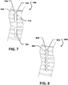
- FIG. 7 depicts yet another tolerance ring 700 having an upper slot 702 and a lower slot 704 formed in an unformed section 706 of a sidewall 708.
- the slots 702, 704 can be separate, discrete, slots 702, 704 that are vertically aligned between adjacent wave structures 710.
- the upper slot 702 can be formed near a top of the sidewall 708 of the tolerance ring 700 and as such, near a top of an elongated wave and the lower slot 704 can be formed near a bottom of the sidewall 708 of the tolerance ring 700 and as such, near a bottom of an elongated wave.
- the upper slot 702 can be formed between adjacent upper waves and the lower slot 704 can be formed between adjacent lower waves.
- Each slot 702, 704 can have a length, L S , and each upper and lower wave can have a length, L W .
- L S can be ⁇ 75% L W , such as ⁇ 80% L W , ⁇ 85% L W , ⁇ 90% L W , ⁇ 95% L W , or ⁇ 100% L W .
- L S can be ⁇ 200% L W , such as ⁇ 175% L W , ⁇ 150% L W , or ⁇ 125% L W .
- L S can be within a range of any of the percentage of L W values described herein.
- the tolerance ring 800 includes a plurality of closely spaced, vertically aligned holes 802 formed radially through the unformed section 804 of the sidewall 806.
- the size and distance between the holes 802 can be modified in order to modify the weakness imparted to the unformed section 804 of the sidewall 806. For example, increasing the hole diameter 802 and decreasing the distance between the holes 802 can increase the weakness in the unformed section 804 of the sidewall 806. Conversely, decreasing the hole diameter 802 and increasing the distance between the holes 802 can decrease the weakness in the unformed section 804 of the sidewall 806.
- the holes 802 can have the same diameter or different diameters.
- a hole 802 located along the vertical center of the tolerance ring 800 can have the smallest diameter and the remaining holes 802 can progressively increase in diameter toward a top and a bottom of the tolerance ring 800.
- a hole 802 located along the vertical center of the tolerance ring 800 can have the largest diameter and the remaining holes 802 can progressively decrease in diameter toward a top and a bottom of the tolerance ring 800.
- a tolerance ring can be made from a metal, a metal alloy, or a combination thereof.
- the metal can include a ferrous metal.
- the metal can include steel.
- the steel can include stainless steel, such as austenitic stainless steel.
- the steel can include stainless steel comprising chrome, nickel, or a combination thereof.
- the steel can X10CrNi18-8 stainless steel.
- the tolerance ring can include a Vickers pyramid number hardness, VPN, which can be ⁇ 350, such as ⁇ 375, ⁇ 400, ⁇ 425, or ⁇ 450. VPN can also be ⁇ 500, ⁇ 475, or ⁇ 450.
- the tolerance ring can be treated to increase its corrosion resistance.
- the tolerance ring can be passivated.
- the tolerance ring can be passivated according to the ASTM standard A967.
- the stock material from which the tolerance ring can be formed can have a thickness, t, and t can be ⁇ 0.085 mm, such as ⁇ 0.087 mm, ⁇ 0.090 mm, ⁇ 0.095 mm, or ⁇ 0.100 mm.
- t can be ⁇ 0.115 mm, ⁇ 0.113 mm, ⁇ 0.110 mm, or ⁇ 0.105 mm.
- t can be within a range between, and including, any of the values of t disclosed above.
- the tolerance ring may have an overall outer diameter, OD, and OD can be ⁇ 5 mm, such as ⁇ 6 mm, ⁇ 7 mm, ⁇ 8 mm, ⁇ 9 mm, or ⁇ 10 mm.
- the OD can be ⁇ 20 mm, such as ⁇ 15 mm, ⁇ 14 mm, ⁇ 13 mm, ⁇ 12 mm, or ⁇ 10 mm. Further, OD can be within a range between and including any of the values of OD described herein.
- the tolerance ring can have an overall length, L, and L can be ⁇ 20 mm, such as ⁇ 17 mm, ⁇ 15 mm, ⁇ 14 mm, or ⁇ 13 mm.
- L can be ⁇ 5 mm, ⁇ 6 mm, ⁇ 7 mm, ⁇ 8 mm, ⁇ 9 mm, or ⁇ 10 mm.
- L can be within a range between, and including, any of the values of L described above.
- the resulting tolerance ring is substantially free of any burrs. Specifically, no burrs are visible along any of the cut edges under a visual inspection of the tolerance ring under 10x magnification.
- a tolerance ring is manufactured from X10CrNi18-8 stainless steel stock.
- the stainless steel stock has a thickness of 0.1 mm ⁇ 0.013. Further, the stainless steel stock has a VPN of 400-450 and is passivated according to ASTM standard A967.
- the formed tolerance ring includes thirteen wave columns equally spaced around the circumference of the sidewall. The distance between the centers of each adjacent pair of wave columns along the circumference of the sidewall is approximately 2.62 mm.
- each wave column includes three waves that are vertically aligned.
- the upper wave and the lower wave are approximately 1.66 mm wide and 3.0 mm tall.
- the middle wave is approximately 1.66 mm wide and 1.5 mm tall.
- the tolerance ring has an overall wall thickness after installation of about 0.3 mm. Further, the tolerance ring has an overall free-state diameter of 11.5 mm and an overall length of 12.5 mm.
- the tolerance ring includes twelve slots formed in the unformed sections of the sidewall. Specifically, a slot is formed in the unformed section of sidewall between each adjacent pair of wave columns. Each slot is centered between the wave columns and centered along a length of the tolerance ring. Each slot is approximately 0.6 mm wide and 10 mm long.
- the tolerance ring is installed around a post having an outer diameter of 11.135 mm and this assembly is installed within a ring having a bore of approximately 11.722 mm.
- This assembly is suspended using fishing line and two lasers are placed perpendicular to a flat face of the ring on the same side of the ring. The lasers are placed 180 degrees from each other. One laser is used as a reference laser and the other laser is used as a measurement laser.
- the ring is tapped under the measurement laser using a hammer that has a force transducer incorporated therein.
- FIG. 9 depicts a Hammer Test setup for on-axis axial stiffness testing.
- the tolerance ring is installed around a post 902 having an outer diameter of 11.135 mm and this assembly is installed within a ring 904 having a bore of approximately 11.722 mm.
- This assembly is suspended using fishing lines 906 and two lasers are placed perpendicular to a flat face of the ring 908 on the same side of the ring.
- the lasers are placed 180 degrees from each other.
- One laser is used as a reference laser R and the other laser is used as a measurement laser M.
- the post is tapped on-axis as indicated by the arrow labeled H from the side opposite of the lasers.
- the lasers and the force transducer of the hammer are coupled to a microprocessor and provide inputs to the microprocessor.
- FIG. 10A illustrates the Hammer Test setup for off-axis axial stiffness testing.
- the tolerance ring is installed around a post having and within a ring as shown in FIG. 9 and suspended using fishing lines.
- two lasers are placed perpendicular to a flat face of the ring on the same side of the ring.
- the lasers are placed 180 degrees from each other.
- One laser is used as a reference laser and the other laser is used as a measurement laser.
- the ring is tapped off-axis under the measurement laser as indicated by the arrow labeled H using a hammer that has a force transducer incorporated therein.
- the lasers and the force transducer of the hammer are coupled to a microprocessor and provide inputs to the microprocessor.
- FIG. 10B illustrates how the input is processed to compensate for the rocking mode R M and axial mode A M induced by the off-axis tap.
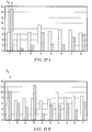
- FIGs. 11A and 11B display the test results of on-axis and off-axis axial stiffness for various tolerance ring.
- the columns have the following designations.
- the F R provides the average resonant frequency in kHz of the ring; the ⁇ is the determined average percent difference around ring.
- Comparison B Tolerance Ring 3 twelve wave quad ring 9 plannish (unformed) opposite gap 4
- Double band Comp. ring 10 Center wave opposite gap 5 six wave pitch corrected 11 Ring with slits 6 seven wave pitch corrected
- Ring 1 is a comparison ring being a 13 wave hard disc drive tolerance ring with three bands.
- Ring 2 is an eight wave ring in 4 groups.
- Ring 3 is a twelve waves tolerance ring in four groups.
- Ring 4 is similar to ring 1 but includes a double band.
- Ring 5 has six wave that are pitch corrected.
- Pitch corrected rings have waves distributed around the assembly with equal angular spacing.
- Rings 6 and 7 have a seven wave and eight wave pitch corrected arrangement, respectively.
- Ring 8 is a second comparison ring made from a new assembly batch having a 13 wave three band arrangement.
- Ring 9 has an unformed ("plannish") region opposite gap.
- Ring 10 has a centered wave opposite gap.
- Ring 11 is a 12 wave pitch corrected ring having slits located between waves. The slits have a length substantially to the length of the wave columns.
- the radial stiffness of the ring in a dummy assembly is measured using a hammer test in 2 places; at the gap and at 90 degrees to the gap. The % difference is calculated between the average of 5 rings tested with 5 hits at each place. Since the tests were carried out with the same dummy masses, the resonant frequency is reported rather than the stiffness for ease of calculation, Equation 1.
- the radial stiffness of the ring in a dummy assembly is measured using a hammer test in 2 places; at the gap and at 90 degrees to the gap. The % difference is calculated between the average of 5 rings tested with 5 hits at each place. Since the tests were carried out with the same dummy masses, the resonant frequency is reported rather than the stiffness for ease of calculation, Equation 1.
- f 1 2 ⁇ ⁇ k m wherein f is the resonant frequency, m is the effective mass, and k is the stiffness of the test piece.
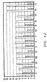
- FIG. 12 depicts the test results of radial stiffness testing for various tolerance ring.
- the columns have the same designations as in FIGs. 11A and 11B and as disclosed below.
- the F R provides the average resonant frequency in kHz of the ring; the ⁇ is the determined average percent difference around ring.
- Ring 2A has a 40 lbf remaining assembly force.
- Ring 3B has 30 lbf remaining assembly force.
- Ring 12 is a 12 wave pitch corrected ring having holes between wave column, more specifically two holes between two waves.
- Ring 13 is an eleven wave pitch corrected.
- Ring 14 is a ring with housing variable, i.e. the ring can be squeezed to conform to a central bore.
- Ring 15 is a ring whit closed housing variable, i.e., the ring is smaller in diameter than its bore and can be stretched to conform to the bore.
- FIG. 13 depicts the test results of PAF, IS, and IS/PAF testing for various tolerance ring.
- the columns have the same designations as in FIGs. 11A, 11B , and 12 .
- PAF and IS are in lbf and IS/PAF is in %
- the lasers and the force transducer of the hammer are coupled to a microprocessor and provide inputs to the microprocessor.
- the microprocessor includes software that calculates resonant frequencies from the inputs provided by the hammer and the lasers.
- the resonant frequency is directly related to the axial stiffness of the tolerance ring.
- the resonant frequency measured along an axis that bisects the gap and passes through a center of the assembly is about 9.8 kHz.
- the resonant frequency measured along an axis perpendicular to the first axis is about 10.1 kHz which is a difference of about 3.2%.
- the axial stiffness through the gap, AS G is about 96.8% of the axial stiffness perpendicular to the gap, AS PG .
- the tolerance rings described herein include slots formed in the sidewall.
- the slots can provide a tolerance ring having a resonant frequency and stiffness that do not substantially vary circumferentially around the tolerance ring.
- the tolerance ring can maintain the post in alignment within the bore and can substantially prevent any rocking of the post within the bore under normal operational loads in nearly any radial direction.
Landscapes
- Engineering & Computer Science (AREA)
- General Engineering & Computer Science (AREA)
- Mechanical Engineering (AREA)
- Moving Of Heads (AREA)
- Rolling Contact Bearings (AREA)
- Mounting Of Bearings Or Others (AREA)
- Turbine Rotor Nozzle Sealing (AREA)
- Prostheses (AREA)
Description
- The present disclosure is directed to tolerance rings, particularly to tolerance rings for actuator arms within hard disk drives.
- This disclosure relates to tolerance ring assemblies, wherein a tolerance ring provides an interference fit between parts of an assembly, in which a first part has a cylindrical portion located in a cylindrical bore of a second part. Further, this disclosure particularly relates to assemblies having a tolerance ring that provides an interference fit between a cylindrical component such as a shaft or a bearing and a housing for the shaft.
- Improved engineering techniques have resulted in the need for greater accuracy of machine parts, raising manufacturing costs. Very close tolerances are required where press fits, splines, pins or keyways are employed to transmit torque in applications such as pulleys, flywheels or driveshafts.
- Tolerance rings may be used to provide an interference fit between parts required to transmit torque. Tolerance rings provide a low cost means of providing an interference fit between parts that may not be machined to exact dimensions. Tolerance rings have a number of other potential advantages, such as compensating for different linear coefficients of expansion between the parts, allowing rapid apparatus assembly, and durability.
- A tolerance ring generally comprises a strip of resilient material, for example a metal such as spring steel, the ends of which are brought together to form a ring. A band of protrusions extend radially outwards from the ring, or radially inwards towards the center of the ring. Usually, the protrusions are formations, possibly regular formations, such as corrugations, ridges or waves.
- When the ring is located in the annular space between, for example, a shaft and a bore in a housing in which the shaft is located, the protrusions are compressed. Each protrusion acts as a spring and exerts a radial force against the shaft and the surface of the bore, providing an interference fit between the shaft and the housing. Rotation of the housing or the shaft will produce similar rotation in the other of the shaft or the housing, as torque is transmitted by the tolerance ring. Typically, the band of protrusions is axially flanked by annular regions of the ring that have no formations (known in the art as "unformed regions" of the tolerance ring).
-
US 2012/0087044 A1 describes a tolerance ring including a hollow cylindrical body defining a longitudinal axis that passes axially through its center. A circumferential gap divides the hollow cylindrical body so that the hollow cylindrical body includes first and second longitudinal edges that define the circumferential gap. A plurality of bumps protrudes radially from the hollow cylindrical body, and consists of a plurality of gap-adjacent bumps and a plurality of non-gap-adjacent bumps. At least one of the plurality of bumps is circumferentially between the gap and each of the non-gap-adjacent bumps. None of the plurality of bumps is circumferentially between the gap and each of the gap-adjacent bumps. The tolerance ring includes a means for increasing an otherwise lower average radial compressive stiffness of the gap-adjacent bumps to become substantially equal to an average radial stiffness of the non-gap-adjacent bumps. - Although tolerance rings usually comprise a strip of resilient material that is curved to allow the easy formation of a ring by overlapping the ends of the strip, a tolerance ring may also be manufactured as an annular band. The term "tolerance ring" as used hereafter includes both types of tolerance ring. The term "shaft" as used hereafter includes any assembly component with a cylindrical portion, such as a shaft or a bearing.
- Accordingly, the industry continues to need improvements in tolerance rings, particularly tolerance rings installed within hard disk drives.
- The present disclosure can be better understood, and its numerous features and advantages made apparent to those skilled in the art by referencing the accompanying drawings.
-
FIG. 1 includes an exploded perspective view of a hard disk drive assembly in accordance with an embodiment. -
FIG. 2 includes a cross-sectional view of a hard disk drive assembly in accordance with an embodiment. -
FIG. 3 includes a perspective view of a tolerance ring in accordance with an embodiment. -
FIG. 4 includes a cross-sectional view of a tolerance ring in accordance with an embodiment taken along Line 4-4 inFIG. 3 . -
FIG. 5 includes a perspective view of a tolerance ring in accordance with another embodiment. -
FIG. 6 includes a perspective view of a tolerance ring in accordance with yet another embodiment. -
FIG. 7 includes a partial perspective view of a tolerance ring in accordance with still another embodiment. -
FIG. 8 includes a partial perspective view of a tolerance ring in accordance with yet still another embodiment. -
FIG. 9 includes a Hammer Test setup for testing on-axis axial stiffness. -
FIGs. 10A and 10B illustrate a Hammer Test for testing off-axial stiffness. -
FIGs. 11A and 11B include the test results of on- and off-axis axial stiffness for various tolerance rings. -
FIG. 12 includes the test results of radial stiffness for various tolerance rings. -
FIG. 13 includes test results for Peak Assembly Force (PAF), Initial Slip (IS), and ratio of IS/PAF for various tolerance rings. - The use of the same reference symbols in different drawings indicates similar or identical items.
- The following description is directed to tolerance rings, and particularly, to tolerance rings that can be installed within a hard disk drive between a post and a bore formed in an actuator arm. In one aspect, a tolerance ring can be fitted around the pivot and then this pivot ring assembly can be inserted into the bore. Alternatively, the tolerance ring can be inserted into the bore and the pivot can be inserted into the tolerance ring.
- In a typical tolerance ring, the waves nearest to the gap tend to be the weakest, i.e., least stiff, since the waves have a gap on one side and material on the other and the remaining waves in the tolerance ring are flanked by material on both sides. This variation in stiffness can cause performance variables, e.g., resonance and alignment, to be very dependent on a position of the gap in the hard disk drive assembly. Attempting to optimize the gap location for one performance parameter can adversely affect other performance parameters. This, in turn, can compromise overall performance.
- A tolerance ring according to one or more of the embodiments described herein can include a plurality of slots that extend through the sidewall of the tolerance ring at targeted locations within the unformed sections of the tolerance ring in order to impart controlled weaknesses in the sidewall adjacent to one or more waves. For example, a slot can extend along nearly the entire length of the sidewall between two adjacent wave structures to remove nearly all of the unformed section of the sidewall between the wave structures. Removing the unformed section of the sidewall between the wave structures can reduce the stiffness of the adjacent waves since the unformed section provides a strengthening base for the wave structures.
- The slotted tolerance rings disclosed herein can provide a tolerance ring having a resonant frequency and stiffness that do not substantially vary circumferentially around the tolerance ring. As such, the tolerance ring can maintain the post in alignment within the bore and can substantially prevent any rocking of the post within the bore under normal operational loads in nearly any radial direction.
- Referring initially to
FIG. 1 , a hard disk drive assembly is shown and is generally designated 100. The harddisk drive assembly 100 can include anactuator arm 102 for a hard disk drive and apivot assembly 104. - As illustrated, the
actuator arm 102 can include aproximal end 110 and adistal end 112. A plurality of read/writeheads 114 can extend from thedistal end 112 of theactuator arm 102. Moreover, theactuator arm 102 can be formed with abore 116 near theproximal end 110 of theactuator arm 102. -
FIG. 1 further indicates that thepivot assembly 104 can include apivot 120 and atolerance ring 122. Thepivot 120 can include aninner member 124 and anouter member 126 and theouter member 126 can rotate with respect to theinner member 124. - In a particular aspect, the
tolerance ring 122 can fit around thepivot 120 and then, thepivot assembly 104 can be installed within thebore 116. In another aspect, thetolerance ring 122 can be placed within thebore 116 and thepivot 120 can be inserted into thetolerance ring 122. Thetolerance ring 122 can establish an interference fit between theouter member 126 of thepivot 120 and thebore 116 of theactuator arm 102. As such, theactuator arm 102 can rotate with theouter member 126 of thepivot 120 around theinner member 124 of thepivot 120. - Accordingly, as shown in
FIG. 2 , thetolerance ring 122 can be installed within thebore 116 between an outer component, theactuator arm 102, and an inner component, thepivot 120. In a particular aspect, when installed, no portion of thetolerance ring 122 extends beyond the top or bottom of the bore and thetolerance ring 122 can be completely contained within thebore 116. In another aspect, a portion of thetolerance ring 122, e.g., a top, a bottom, a structure on a top, a structure on a bottom, or a combination thereof, can extend from the bore. - As illustrated in
FIG. 2 , and described in greater detail below, thetolerance ring 122 can be configured to engage the inner wall of thebore 116 and the outer wall of thepivot 120 in order to maintain thepivot 120 within theactuator arm 102 in an interference fit. Thetolerance ring 122 can account for dimensional variations by expanding around thepivot 120 as it is installed thereon and then, at least partially deforming, or compressing, within thebore 116 during installation. - Referring now to
FIG. 3 ,FIG. 4 , andFIG. 5 , details concerning thetolerance ring 122 are illustrated. As depicted, thetolerance ring 122 can include a generallycylindrical body 302 having a generallycylindrical sidewall 304. Thesidewall 304 can include a top 306 and a bottom 308. Further, thesidewall 304 can include afirst end 310 and asecond end 312. Moreover, agap 314 can be established between thefirst end 310 and thesecond end 312 of thesidewall 304. Thegap 314 can extend along the entire length of thebody 302 and thegap 314 can establish a split in thebody 302. - As indicated in
FIG. 3 , thebody 302 of thetolerance ring 122 can further include anupper flange 316 extending from the top 306 of thesidewall 304 and alower flange 318 extending from thebottom 308 of thesidewall 304. - The
tolerance ring 122 can include acentral axis 320 and as shown inFIG. 2 andFIG. 3 , in a particular aspect, theflanges central axis 320 of thetolerance ring 122. It is to be understood that theflanges central axis 320. In either case, theflanges central axis 320. In a particular aspect, α can be ≥ 5°, such as ≥ 10°, or ≥ 15°. In another aspect, α can be ≤ 30°, such as ≤ 25°, or ≤ 20°. In another aspect, α can be within a range between, and including, any of the values disclosed above. - As most clearly illustrated in
FIG. 2 , thetolerance ring 122 may include an overall wall thickness, tOW, that is the distance between the inner surface of thesidewall 304 of thetolerance ring 122 and an outer surface of a wall structure formed in thesidewall 304 of thetolerance ring 122. Further, eachflange sidewall 304 such that eachflange sidewall 304 of thetolerance ring 122 and the outer edge of theflange - In certain embodiments that include flanges and wall structures that extend in an inward direction relative to the
central axis 320, tOW can be measured between an outer surface of thesidewall 304 of thetolerance ring 122 and an inner surface of a wall structure formed in thesidewall 304 of thetolerance ring 122. Further, in such embodiments, tOF is measured between the outer surface of thesidewall 304 of thetolerance ring 122 and the inner edge of theflange - Still referring to
FIG. 2 andFIG. 3 , thetolerance ring 122 can include a plurality ofwaves 322 formed in thesidewall 304 of thebody 302. As illustrated, in one aspect, thewaves 322 can extend in an outward direction with respect to thecentral axis 320. However, in another aspect, thewaves 322 can extend in an inward direction with respect to thecentral axis 320. - The
waves 322 can be formed, or otherwise arranged, in thesidewall 304 of thebody 302 so that thetolerance ring 122 includes a plurality of wave structures, such aswave columns 324 that are equally spaced around the circumference of thesidewall 302 of thebody 304 of thetolerance ring 122. - Each
wave column 324 can include at least twowaves 322 vertically aligned with each other along thesidewall 304 of thebody 302 of thetolerance ring 122, e.g., along a length of thetolerance ring 122. - As illustrated in
FIG. 3 , in a particular aspect, eachwave column 324 of thetolerance ring 122 can have afirst wave 330 near the top 306 of thesidewall 304 of thebody 302 of thetolerance ring 122 and asecond wave 332 near thebottom 308 of thesidewall 304 of thebody 302 of thetolerance ring 122. In a particular aspect, thefirst wave 330 can be centered within the top half of the length of thetolerance ring 122. Moreover, thesecond wave 332 can be centered within the bottom half of the length of thetolerance ring 122. Eachwave column 324 can also include athird wave 334 between thefirst wave 330 and thesecond wave 332. Thethird wave 334 can be centered along the length of thetolerance ring 122. - In one aspect, the
first wave 330 can be the same size as thesecond wave 332, e.g., length, width, height (measured from the outer surface of the sidewall 304). In another aspect, thefirst wave 330, thesecond wave 332, and thethird wave 334 are the same size, e.g., length, width, height (measured from the outer surface of the sidewall 304). In particular, thefirst wave 330 and thesecond wave 332 can have a first length, L1, and thethird wave 334 includes a second length, L2, and L2 ≤ L1. Specifically, L2 can be ≤ 75% L1, such as L2 ≤ 70% L1, L2 ≤ 65% L1, L2 ≤ 60% L1, L2 ≤ 55% L1, or L2 ≤ 50% L1. In another aspect, L2 can be ≥ 25% L1, such as L2 ≥ 30% L1, L2 ≥ 35% L1, or L2 ≥ 40% L1. In another aspect, L2 can be within a range between, and including, any of the percentage values of L1 disclosed above. -
FIG. 3 ,FIG. 4 , andFIG. 5 further indicate that thesidewall 304 of thebody 302 of thetolerance ring 122 can include a plurality of unformed sections 340. Each unformed section 340 can comprise a section of thesidewall 304 that extends betweenadjacent wave columns 324 and is not formed with any waves or other structures. Moreover, each unformed section 340 can extend betweenadjacent wave columns 324 between theupper flange 316 and thelower flange 318 of thebody 302 without any additional structure or feature formed between theflanges - As indicated in
FIG. 5 , thewave columns 324 and the unformed sections 340 can alternate around the circumference of thesidewall 304. Moreover, in a particular aspect, thewave columns 324 are evenly spaced around the circumference of thesidewall 304 by the unformed sections 340 of thesidewall 304. -
FIG. 3 andFIG. 5 indicate that thesidewall 304 of thebody 302 of thetolerance ring 122 can be formed with a plurality ofslots 342 that can extend radially through thesidewall 304 of thebody 302. In particular, theslots 342 can extend along the unformed sections 340 of thesidewall 304. In a particular aspect, thebody 302 has a length, L, and the slot has a length, LS. Further, LS ≥ 80% L, such as ≥ 85% L, or ≥ 90% L. In another aspect, LS ≤ 99% L, such as ≤ 98% L, ≤ 97% L, ≤ 96% L, ≤ 95% L. Moreover, LS can be within a range between, and including, any of the percentage of L values described herein. - In another aspect, each unformed section 340 has a width, WUS. Further, each
slot 342 has a width, WS. In a particular aspect, WS can be ≥ 50% WUS, such as ≥ 55% Wus, ≥ 60% WUS, ≥ 65% WUS, ≥ 70% WUS, ≥ 75% WUS, ≥ 80% WUS, ≥ 85% WUS, or ≥ 90% WUS. In another aspect, WS can be ≤ 99% WUS, such as ≤ 98% WUS, ≤ 97% WUS, ≤ 96% WUS, or ≤ 95% WUS. WS can be within a range between, and including, any of the percentage of WUS values described above. - In yet another aspect, each wave structure has an overall length, LWS. For a wave column, LWS can be measured from a top of an upper wave and a bottom of a lower wave. For an elongated wave, described below, LWS can be measured from the top of the elongated wave to the bottom of the elongated wave. In a particular aspect, LS can be ≥ 50% LWS, such as ≥ 55% LWS, ≥ 60% LWS, ≥ 65% LWS, ≥ 70% LWS, ≥ 75% LWS, ≥ 80% LWS, ≥ 85% LWS, ≥ 90% LWS, or ≥ 95% LWS. Moreover, LS can be ≤ 110% LWS, such as ≤ 109% LWS, ≤ 108% LWS, ≤ 107% LWS, ≤ 106% LWS, or ≤ 105% LWS. LS can be within a range between, and including, any of the percentage of LWS values described above.
- In another aspect, each
slot 342 can includes a first end and a second end and each end can be rounded. Further, eachslot 342 is centered circumferentially and longitudinally within each unformed section 340. - In a particular aspect, an unformed section without a
slot 342, i.e., a solid unformed section, can include a circumferential wave-to-wave force transfer, FT, in which force exerted on one wave structure is transmitted through the solid unformed section to an adjacent wave structure. In certain applications, a relatively high FT can be undesirable. Removing a portion, or nearly all, of the unformed section can substantially reduce FT and an unformed section 340 having aslot 342 formed therein can have a circumferential wave-to-wave transfer, FTS, which is less than FT. For example, FTS, can be ≤ 50% FT, such as ≤ 45% FT, ≤ 40% FT, ≤ 35% FT, ≤ 30% FT, ≤ 25% FT, ≤ 20% FT, ≤ 15% FT, or ≤ 10% FT. Further, FTS can be ≥ 1% FT, such as ≥ 2% FT, ≥ 3% FT, ≥ 4% FT, or ≥ 5% FT. In another aspect, FTS can be within a range between, and including, any of the percentage of FT values described above. - Removing a portion of the
unformed section 342 adjacent to awave 322, or wave structure, can alter the stiffness of theadjacent wave 322. In particular, by removing a portion of thewave 322, the stiffness of the adj acent wave can be reduced from anidentical wave 322 not adjacent to a slottedunformed section 342. In other words, a wave adjacent to an unslottedunformed section 342 can include a stiffness, S, and after aslot 342 is cut, punched, or otherwise made, in anunformed section 342 adjacent to thewave 322, the resulting wave can have a stiffness, SS. SS can be less than S. For example, Ss can be ≤ 95% S, such as SS ≤ 90% S, ≤ 85% S, ≤ 80% S, ≤ 75% S, ≤ 70% S, or ≤ 65% S. Moreover, SS can be ≥ 25% S, such as ≥ 30% S, ≥ 35% S, ≥ 40% S, ≥ 45% S, or ≥ 50% S. In another aspect, SS can be within a range between, and including, any of the percentage of S values described above. -
FIG. 4 indicates that thetolerance ring 122 can include acentral axis 350 that can pass through acenter 352 of thetolerance ring 122 and bisect thegap 314. In a particular aspect, thetolerance ring 122 can be symmetric about thecentral axis 350. - In a particular aspect, when the
pivot assembly 104 is installed within thebore 116 of the actuator arm with thetolerance ring 122 disposed there between, thepivot 120 and thebore 116 can include a central axis that lies along, or nearly along, thecentral axis 320 of thetolerance ring 122. Thetolerance ring 122 can provide an axial stiffness that can substantially resist rocking movement of thepivot 120 relative to thebore 116 and theactuator arm 102 in which the central axis of thepivot 120 rotates about an axis perpendicular to the central axis (a longitudinal axis) with respect to thecentral axis 320. - When left unconstrained, such rocking motion can cause the read/write heads 114 to contact a hard disk. This contact is undesired and can cause failure of a hard disk drive. By modifying the unformed sections adjacent to wave structures as described herein, the axial stiffness of the
tolerance ring 122 can be manipulated to substantially reduce any variations in the axial stiffness caused by the reduction in axial stiffness due to thegap 314. Further, by modifying the unformed sections adjacent to the wave structures, the axial stiffness of thetolerance ring 122 can be manipulated so that the axial stiffness of thetolerance ring 122 does not vary too greatly when measured at various locations circumferentially around thetolerance ring 122. - For example, the axial stiffness of the
tolerance ring 122 through thegap 314, ASG, can be measured in a first direction that passes through thegap 314 and a center 360 of thetolerance ring 122. The axial stiffness of thetolerance ring 122 perpendicular to thegap 314, ASPG, can be measured in a second direction perpendicular to the first direction. ASG can be ≥ 90% ASPG, such as ≥ 91% ASPG, ≥ 92% ASPG, ≥ 93% ASPG, ≥ 94% ASPG, ≥ 95% ASPG, or ≥ 96% ASPG. Further, ASG can be ≤ 100% ASPG, ≤ 99% ASPG, ≤ 98% ASPG, or ≤ 97% ASPG. Moreover, ASG can be within a range between, and including, any of the percentage values of ASPG disclosed above. - Additionally, the resonant frequency of the
tolerance ring 122 does not vary greatly when measured at various locations circumferentially the assembly in which thetolerance ring 122 is installed. For example, the resonant frequency of thetolerance ring 122 through thegap 314, RFG, can be measured in a first direction that passes through thegap 314 and the center 360 of thetolerance ring 122. The resonant frequency of thetolerance ring 122 perpendicular to thegap 314, RFPG, can be measured in a second direction perpendicular to the first direction. RFG can be ≥ 90% RFPG, such as ≥ 91% RFPG, ≥ 92% RFPG, ≥ 93% RFPG, ≥ 94% RFPG, or ≥ 95% RFPG. Further, RFG can be ≤ 100% RFPG, ≤ 99% RFPG, ≤ 98% RFPG, ≤ 97% RFPG, or ≤ 96% RFPG. Moreover, RFG can be within a range between, and including, any of the percentage values of RFPG disclosed above. - Referring now to
FIG. 5 , in another aspect, each wave structure can include a singleelongated wave 500. Theelongated waves 500 can extend longitudinally along asidewall 502 of abody 504 of atolerance ring 506. Further, eachelongated wave 500 can extend substantially along a length of thesidewall 502 of thetolerance ring 506 between anupper flange 508 and alower flange 510. Thetolerance ring 506 can also include agap 514. In this aspect, eachelongated wave 500 can be centered along the length of thetolerance ring 500. Moreover, this aspect of thetolerance ring 500 can include one or more of the features or characteristics described herein with respect to the other tolerance rings disclosed herein. In this aspect, aslot 512 can be formed in thesidewall 502 of thetolerance ring 506 within anunformed section 514 between adjacentelongated waves 500. Further, the tolerance ring can include agap 516. - In each embodiment described herein, two wave structures, e.g., elongated waves, wave columns, or a combination thereof, will always be located circumferentially closer to a
gap gap gap 314 can include a first wave stiffness, SW1. The other wave structures that are adjacent to unformed sections can include a second wave stiffness, SW2. Without modification of thetolerance ring tolerance ring - However, modifying the
wave structures wave structures unformed sections 340, 614 between thewave structures slots unformed sections sidewall gap slots sidewall gap slots 322, 600 can increase in size, e.g., length, width, or a combination thereof, along the circumference of thesidewall gap sidewall gap 314, 516 (i.e., 180° from thegap 314, 516). -
FIG. 6 shows another tolerance ring 600 formed withslots 602 in theunformed sections 604 of thesidewall 606. As illustrated, theslots 602 can be bifurcated, or otherwise split, by aslot bridge 608. In a particular aspect, the slot bridge can alter the wave stiffness adjacent at or near the bridged slot, WSBS, so that a wave stiffness of a wave adjacent to a slot, WSS, is less than WSBS. WSBS can be associated with a single wave, e.g., a central wave in a wave column, or a portion of a wave, e.g., a middle of an elongated wave. By altering the stiffness of a central wave or a central portion of a wave, the tolerance ring 600 can retain structural rigidity through the middle of the tolerance ring while still providing an axial stiffness that only slightly varies in various directions at the top and bottom of the tolerance ring. - In a particular aspect, WSS can be ≤ 50% WSBS, such as ≤ 45% WSBS, ≤ 40% WSBS, ≤ 35% WSBS, ≤ 30% WSBS, ≤ 25% WSBS, or ≤ 20% WSBS. In another aspect, WSS, can be ≥ 1% WSBS, such as ≥ 2% WSBS, ≥ 3% WSBS, ≥ 4% WSBS, or ≥ 5% WSBS. Moreover, WSS can be within a range between, and including, any of the percentage of WSBS values.
-
FIG. 7 depicts yet anothertolerance ring 700 having anupper slot 702 and alower slot 704 formed in anunformed section 706 of asidewall 708. Theslots slots adjacent wave structures 710. In one aspect, theupper slot 702 can be formed near a top of thesidewall 708 of thetolerance ring 700 and as such, near a top of an elongated wave and thelower slot 704 can be formed near a bottom of thesidewall 708 of thetolerance ring 700 and as such, near a bottom of an elongated wave. In another aspect, theupper slot 702 can be formed between adjacent upper waves and thelower slot 704 can be formed between adjacent lower waves. Eachslot - Referring to
FIG. 8 , another embodiment of a tolerance ring is shown and is generally designated 800. As illustrated, thetolerance ring 800 includes a plurality of closely spaced, vertically alignedholes 802 formed radially through theunformed section 804 of thesidewall 806. The size and distance between theholes 802 can be modified in order to modify the weakness imparted to theunformed section 804 of thesidewall 806. For example, increasing thehole diameter 802 and decreasing the distance between theholes 802 can increase the weakness in theunformed section 804 of thesidewall 806. Conversely, decreasing thehole diameter 802 and increasing the distance between theholes 802 can decrease the weakness in theunformed section 804 of thesidewall 806. - In a particular aspect, the
holes 802 can have the same diameter or different diameters. For example, ahole 802 located along the vertical center of thetolerance ring 800 can have the smallest diameter and the remainingholes 802 can progressively increase in diameter toward a top and a bottom of thetolerance ring 800. Alternatively, ahole 802 located along the vertical center of thetolerance ring 800 can have the largest diameter and the remainingholes 802 can progressively decrease in diameter toward a top and a bottom of thetolerance ring 800. - In a particular aspect, a tolerance ring according to any of the aspects described herein can be made from a metal, a metal alloy, or a combination thereof. The metal can include a ferrous metal. Further, the metal can include steel. The steel can include stainless steel, such as austenitic stainless steel. Moreover, the steel can include stainless steel comprising chrome, nickel, or a combination thereof. For example, the steel can X10CrNi18-8 stainless steel. Further, the tolerance ring can include a Vickers pyramid number hardness, VPN, which can be ≥ 350, such as ≥ 375, ≥ 400, ≥ 425, or ≥ 450. VPN can also be ≤ 500, ≤ 475, or ≤ 450. VPN can also be within a range between, and including, any of the VPN values described herein. In another aspect, the tolerance ring can be treated to increase its corrosion resistance. In particular, the tolerance ring can be passivated. For example, the tolerance ring can be passivated according to the ASTM standard A967.
- In another aspect, the stock material from which the tolerance ring can be formed can have a thickness, t, and t can be ≥ 0.085 mm, such as ≥ 0.087 mm, ≥ 0.090 mm, ≥ 0.095 mm, or ≥ 0.100 mm. In another aspect, t can be ≤ 0.115 mm, ≤ 0.113 mm, ≤ 0.110 mm, or ≤ 0.105 mm. Moreover, t can be within a range between, and including, any of the values of t disclosed above.
- The tolerance ring according to any of the aspects described herein may have an overall outer diameter, OD, and OD can be ≥ 5 mm, such as ≥ 6 mm, ≥ 7 mm, ≥ 8 mm, ≥ 9 mm, or ≥ 10 mm. The OD can be ≤ 20 mm, such as ≤ 15 mm, ≤ 14 mm, ≤ 13 mm, ≤ 12 mm, or ≤ 10 mm. Further, OD can be within a range between and including any of the values of OD described herein.
- In another aspect, the tolerance ring can have an overall length, L, and L can be ≤ 20 mm, such as ≤ 17 mm, ≤ 15 mm, ≤ 14 mm, or ≤ 13 mm. L can be ≥ 5 mm, ≥ 6 mm, ≥ 7 mm, ≥ 8 mm, ≥ 9 mm, or ≥ 10 mm. Moreover, L can be within a range between, and including, any of the values of L described above.
- Additionally, after the stock material that is used to form any of the tolerance rings described herein is cut, stamped, and rolled to form the tolerance ring, the resulting tolerance ring is substantially free of any burrs. Specifically, no burrs are visible along any of the cut edges under a visual inspection of the tolerance ring under 10x magnification.
- A tolerance ring is manufactured from X10CrNi18-8 stainless steel stock. The stainless steel stock has a thickness of 0.1 mm ± 0.013. Further, the stainless steel stock has a VPN of 400-450 and is passivated according to ASTM standard A967. The formed tolerance ring includes thirteen wave columns equally spaced around the circumference of the sidewall. The distance between the centers of each adjacent pair of wave columns along the circumference of the sidewall is approximately 2.62 mm.
- Further, each wave column includes three waves that are vertically aligned. The upper wave and the lower wave are approximately 1.66 mm wide and 3.0 mm tall. The middle wave is approximately 1.66 mm wide and 1.5 mm tall. The tolerance ring has an overall wall thickness after installation of about 0.3 mm. Further, the tolerance ring has an overall free-state diameter of 11.5 mm and an overall length of 12.5 mm.
- The tolerance ring includes twelve slots formed in the unformed sections of the sidewall. Specifically, a slot is formed in the unformed section of sidewall between each adjacent pair of wave columns. Each slot is centered between the wave columns and centered along a length of the tolerance ring. Each slot is approximately 0.6 mm wide and 10 mm long.
- The tolerance ring is installed around a post having an outer diameter of 11.135 mm and this assembly is installed within a ring having a bore of approximately 11.722 mm. This assembly is suspended using fishing line and two lasers are placed perpendicular to a flat face of the ring on the same side of the ring. The lasers are placed 180 degrees from each other. One laser is used as a reference laser and the other laser is used as a measurement laser. The ring is tapped under the measurement laser using a hammer that has a force transducer incorporated therein.
-
FIG. 9 depicts a Hammer Test setup for on-axis axial stiffness testing. The tolerance ring is installed around apost 902 having an outer diameter of 11.135 mm and this assembly is installed within aring 904 having a bore of approximately 11.722 mm. This assembly is suspended usingfishing lines 906 and two lasers are placed perpendicular to a flat face of thering 908 on the same side of the ring. The lasers are placed 180 degrees from each other. One laser is used as a reference laser R and the other laser is used as a measurement laser M. The post is tapped on-axis as indicated by the arrow labeled H from the side opposite of the lasers. The lasers and the force transducer of the hammer are coupled to a microprocessor and provide inputs to the microprocessor. -
FIG. 10A illustrates the Hammer Test setup for off-axis axial stiffness testing. The tolerance ring is installed around a post having and within a ring as shown inFIG. 9 and suspended using fishing lines. As inFIG. 9 , two lasers are placed perpendicular to a flat face of the ring on the same side of the ring. The lasers are placed 180 degrees from each other. One laser is used as a reference laser and the other laser is used as a measurement laser. The ring is tapped off-axis under the measurement laser as indicated by the arrow labeled H using a hammer that has a force transducer incorporated therein. The lasers and the force transducer of the hammer are coupled to a microprocessor and provide inputs to the microprocessor.FIG. 10B illustrates how the input is processed to compensate for the rocking mode RM and axial mode AM induced by the off-axis tap. -
FIGs. 11A and 11B display the test results of on-axis and off-axis axial stiffness for various tolerance ring. InFIGs. 11A and 11B , the columns have the following designations. The FR provides the average resonant frequency in kHz of the ring; the Δ is the determined average percent difference around ring.1 Comparison A Tolerance Ring 7 eight wave pitch corrected 2 eight wave quad ring 8 Comparison B Tolerance Ring 3 twelve wave quad ring 9 plannish (unformed) opposite gap 4 Double band Comp. ring 10 Center wave opposite gap 5 six wave pitch corrected 11 Ring with slits 6 seven wave pitch corrected -
Ring 1 is a comparison ring being a 13 wave hard disc drive tolerance ring with three bands.Ring 2 is an eight wave ring in 4 groups.Ring 3 is a twelve waves tolerance ring in four groups.Ring 4 is similar toring 1 but includes a double band.Ring 5 has six wave that are pitch corrected. Pitch corrected rings have waves distributed around the assembly with equal angular spacing.Rings Ring 8 is a second comparison ring made from a new assembly batch having a 13 wave three band arrangement.Ring 9 has an unformed ("plannish") region opposite gap.Ring 10 has a centered wave opposite gap.Ring 11 is a 12 wave pitch corrected ring having slits located between waves. The slits have a length substantially to the length of the wave columns. - The radial stiffness of the ring in a dummy assembly is measured using a hammer test in 2 places; at the gap and at 90 degrees to the gap. The % difference is calculated between the average of 5 rings tested with 5 hits at each place. Since the tests were carried out with the same dummy masses, the resonant frequency is reported rather than the stiffness for ease of calculation,
Equation 1. - The radial stiffness of the ring in a dummy assembly is measured using a hammer test in 2 places; at the gap and at 90 degrees to the gap. The % difference is calculated between the average of 5 rings tested with 5 hits at each place. Since the tests were carried out with the same dummy masses, the resonant frequency is reported rather than the stiffness for ease of calculation,
Equation 1.
-
FIG. 12 depicts the test results of radial stiffness testing for various tolerance ring. InFIG. 12 , the columns have the same designations as inFIGs. 11A and 11B and as disclosed below. The FR provides the average resonant frequency in kHz of the ring; the Δ is the determined average percent difference around ring.3A 12 wave quad ring 40lbf PAF 13 eleven wave pitch corrected 3B 12 wave quad ring 30 lbf PAF 14 Ring housing variable 12 Ring w/ holes 15 Ring with closed housing variable - Ring 2A has a 40 lbf remaining assembly force.
Ring 3B has 30 lbf remaining assembly force.Ring 12 is a 12 wave pitch corrected ring having holes between wave column, more specifically two holes between two waves.Ring 13 is an eleven wave pitch corrected.Ring 14 is a ring with housing variable, i.e. the ring can be squeezed to conform to a central bore.Ring 15 is a ring whit closed housing variable, i.e., the ring is smaller in diameter than its bore and can be stretched to conform to the bore. - For Peak assembly and initial slip testing, first the torque of a pivot is tested. The pivot is then assembled into an arm using the relevant tolerance ring and the peak assembly force (PAF) is recorded. The torque of the assembly is then tested and the difference between unassembled and assembled torque, or 'torque shift' is recorded. Next, the assembly is disassembled, and the initial slip is recorded and finally, the torque of the pivot is measured again. The pivot is re used until the post-assembled torque is considered high, or 5 times, whichever occurs first. The arm is re-used 5 times. These reusage policies are the result of previous investigation and shouldn't cause any problems, but it should be borne in mind that the pivot and arm are not virgin each time.
-
FIG. 13 depicts the test results of PAF, IS, and IS/PAF testing for various tolerance ring. InFIG. 13 , the columns have the same designations as inFIGs. 11A, 11B , and12 . PAF and IS are in lbf and IS/PAF is in % - The lasers and the force transducer of the hammer are coupled to a microprocessor and provide inputs to the microprocessor. The microprocessor includes software that calculates resonant frequencies from the inputs provided by the hammer and the lasers. The resonant frequency is directly related to the axial stiffness of the tolerance ring. The resonant frequency measured along an axis that bisects the gap and passes through a center of the assembly is about 9.8 kHz. The resonant frequency measured along an axis perpendicular to the first axis is about 10.1 kHz which is a difference of about 3.2%. As such, the axial stiffness through the gap, ASG, is about 96.8% of the axial stiffness perpendicular to the gap, ASPG.
- The tolerance rings described herein include slots formed in the sidewall. The slots can provide a tolerance ring having a resonant frequency and stiffness that do not substantially vary circumferentially around the tolerance ring. As such, the tolerance ring can maintain the post in alignment within the bore and can substantially prevent any rocking of the post within the bore under normal operational loads in nearly any radial direction.
- A skilled artisan can recognize that there may be others applications that can utilize a tolerance ring having one or more of the characteristics described herein.
- The above-disclosed subject matter is to be considered illustrative, and not restrictive, and the appended claims are intended to cover all such modifications, enhancements, and other embodiments, which fall within the true scope of the present invention. Thus, to the maximum extent allowed by law, the scope of the present invention is to be determined by the broadest permissible interpretation of the following claims and their equivalents, and shall not be restricted or limited by the foregoing detailed description.
- In addition, in the foregoing Detailed Description, various features can be grouped together or described in a single embodiment for the purpose of streamlining the disclosure. This disclosure is not to be interpreted as reflecting an intention that the claimed embodiments require more features than are expressly recited in each claim. Rather, as the following claims reflect, inventive subject matter can be directed to less than all features of any of the disclosed embodiments. Thus, the following claims are incorporated into the Detailed Description, with each claim standing on its own as defining separately claimed subject matter.
Claims (15)
- A tolerance ring (122; 506; 700; 800), comprising:
a generally cylindrical body (302) having a sidewall (302; 502; 606; 708; 806) wherein the sidewall (302; 502; 606; 708; 806) includes:a plurality of wave structures (322) extending from the sidewall (302; 502; 606; 708; 806) at regular intervals around the body (302);a first unformed section between a first pair of adjacent wave structures, the first unformed section including a gap (314; 516), wherein the gap (314; 516) extends along an entire length, L, of the body to establish a split in the body (302); anda second unformed section between a second pair of adjacent wave structures, the second unformed section including a slot (342) therein, characterized in that the slot (342) has a length, LS, and LS ≥ 80% L. - The tolerance ring (122; 506; 700; 800) of claim 1, wherein LS ≥ 85% L.
- The tolerance ring (122; 506; 700; 800) of claim 2, wherein LS ≤ 99% L.
- The tolerance ring (122; 506; 700; 800) of claim 1, wherein a solid unformed section without a slot includes a circumferential wave-to-wave force transfer, FT, and the second unformed section with the slot (342) includes a circumferential wave-to-wave force transfer, FTS ≤ 50% FT.
- The tolerance ring (122; 506; 700; 800) of claim 4, wherein FTS ≥ 1% FT.
- The tolerance ring (122; 506; 700; 800) of claim 1, wherein each unformed section has a width, WUS, each slot has a width, WS, and WS ≥ 50% Wus.
- The tolerance ring (122; 506; 700; 800) of claim 6, wherein WS ≤ 99% Wus.
- The tolerance ring (122; 506; 700; 800) of claim 1, wherein each wave structure has a length, LWS, and LS ≥ 50% LWS.
- The tolerance ring (122; 506; 700; 800) of claim 8, wherein LS ≤ 110% LWS.
- The tolerance ring (122; 506; 700; 800) of claim 1, wherein each slot (342) is centered within each unformed section.
- The tolerance ring (122; 506; 700; 800) of claim 1, wherein each wave structure comprises a first wave extending from the sidewall (302; 502; 606; 708; 806) and a second wave extending from the sidewall (302; 502; 606; 708; 806), wherein the second wave is distanced from the first wave, wherein the first wave and the second wave are arranged in a column.
- The tolerance ring (122; 506; 700; 800) of claim 11, wherein each wave column (324) further comprises a third wave (334) extending from the sidewall between the first wave and the second wave.
- The tolerance ring (122; 506; 700; 800) of claim 1, wherein each slot (342) comprises a length, LS, and a width, Ws, and a LS:WS ≥ 10:1.
- A pivot assembly (104), comprising:an outer component (102) including a bore (116) within the outer component (102);an inner component (120) disposed within the bore (116); anda tolerance ring (122; 506; 700; 800) according to claim 1.
- The assembly (104) according to claim 14, wherein the assembly (104) comprises a hard disk drive.
Priority Applications (1)
| Application Number | Priority Date | Filing Date | Title |
|---|---|---|---|
| PL13722513T PL2845192T3 (en) | 2012-04-30 | 2013-04-30 | Tolerance ring with slotted sidewall |
Applications Claiming Priority (2)
| Application Number | Priority Date | Filing Date | Title |
|---|---|---|---|
| US201261640626P | 2012-04-30 | 2012-04-30 | |
| PCT/GB2013/051117 WO2013164608A1 (en) | 2012-04-30 | 2013-04-30 | Tolerance ring with slotted sidewall |
Publications (2)
| Publication Number | Publication Date |
|---|---|
| EP2845192A1 EP2845192A1 (en) | 2015-03-11 |
| EP2845192B1 true EP2845192B1 (en) | 2019-07-17 |
Family
ID=48430847
Family Applications (1)
| Application Number | Title | Priority Date | Filing Date |
|---|---|---|---|
| EP13722513.2A Active EP2845192B1 (en) | 2012-04-30 | 2013-04-30 | Tolerance ring with slotted sidewall |
Country Status (8)
| Country | Link |
|---|---|
| US (1) | US9022683B2 (en) |
| EP (1) | EP2845192B1 (en) |
| JP (1) | JP5923216B2 (en) |
| KR (1) | KR101635729B1 (en) |
| CN (1) | CN104246880B (en) |
| MY (1) | MY186198A (en) |
| PL (1) | PL2845192T3 (en) |
| WO (1) | WO2013164608A1 (en) |
Families Citing this family (18)
| Publication number | Priority date | Publication date | Assignee | Title |
|---|---|---|---|---|
| JP5474710B2 (en) * | 2010-09-03 | 2014-04-16 | 株式会社東郷製作所 | Torque transmission tolerance ring |
| JP5781628B2 (en) * | 2011-12-09 | 2015-09-24 | 日本発條株式会社 | Tolerance ring, hard disk device, and method of manufacturing hard disk device |
| MY172768A (en) | 2012-04-30 | 2019-12-12 | Saint Gobain Performance Plastics Rencol Ltd | Tolerance ring with perforated waves |
| PL2845192T3 (en) | 2012-04-30 | 2020-01-31 | Saint-Gobain Performance Plastics Rencol Limited | Tolerance ring with slotted sidewall |
| CN106460935B (en) | 2014-06-06 | 2021-05-04 | 圣戈班性能塑料万科有限公司 | tolerance ring |
| US10100873B2 (en) * | 2014-12-09 | 2018-10-16 | Ford Global Technologies, Llc | Radially deflectable bushing and steering gear assembly using the same |
| US9908167B1 (en) | 2015-03-02 | 2018-03-06 | Western Digital Technologies, Inc. | Disk drive tolerance ring with edge rounding from opposite major faces |
| JP6341216B2 (en) * | 2016-02-09 | 2018-06-13 | トヨタ自動車株式会社 | Vehicle power transmission device |
| WO2018083021A1 (en) * | 2016-11-01 | 2018-05-11 | Saint-Gobain Performance Plastics Rencol Limited | Friction brake |
| CA3160529A1 (en) | 2019-11-07 | 2021-05-14 | Saint-Gobain Performance Plastics Rencol Limited | Electrically conductive bearings |
| WO2021113599A1 (en) | 2019-12-06 | 2021-06-10 | Saint-Gobain Performance Plastics Corporation | Flanged bearing, assembly, and method of making and using the same |
| EP4073397B1 (en) | 2019-12-13 | 2026-03-25 | Saint-Gobain Performance Plastics Rencol Limited | Assembly comprising a tolerance ring between two components with desired slipping torque at the surfaces of contact |
| EP4086473A1 (en) * | 2021-05-07 | 2022-11-09 | SFS Group International AG | Tolerance ring with stop |
| JP2024520214A (en) | 2021-07-02 | 2024-05-22 | サン-ゴバン パフォーマンス プラスチックス パンプス ゲゼルシャフト ミット ベシュレンクテル ハフツング | Flanged bearings, assemblies, and methods of making and using same |
| KR20240124302A (en) | 2021-12-21 | 2024-08-16 | 생-고뱅 퍼포먼스 플라스틱스 코포레이션 | Electrically conductive bearing having ribs, and method for manufacturing and using the same |
| TWI874880B (en) | 2021-12-30 | 2025-03-01 | 德商聖高拜塑膠製品股份有限公司 | Sliding component, assembly, and method of forming and using the same |
| CA3246552A1 (en) * | 2022-04-01 | 2023-10-05 | Saint-Gobain Performance Plastics Corporation | Torque performance bearings and methods of making and using the same |
| CN121360970B (en) * | 2025-12-19 | 2026-02-27 | 浙江卡环科技有限公司 | Tolerance ring production equipment with automatic positioning and cutting device |
Citations (2)
| Publication number | Priority date | Publication date | Assignee | Title |
|---|---|---|---|---|
| US3700271A (en) * | 1970-04-16 | 1972-10-24 | Star Kugelhalter Gmbh Dt | Spacer ring |
| US20080043375A1 (en) * | 2006-08-15 | 2008-02-21 | Hanrahan Kevin P | Tolerance ring having variable height and/or assymmetrically located bumps |
Family Cites Families (52)
| Publication number | Priority date | Publication date | Assignee | Title |
|---|---|---|---|---|
| US791059A (en) | 1904-08-08 | 1905-05-30 | Fort Wayne Wind Mill Company | Self-adjusting bearing. |
| US2348862A (en) | 1940-02-27 | 1944-05-16 | Fred Goat Co Inc | Registration control apparatus |
| US2813765A (en) | 1953-04-13 | 1957-11-19 | Kenneth C Alward | Cylindrical construction |
| US2978227A (en) | 1958-07-23 | 1961-04-04 | Thompson Ramo Wooldridge Inc | Rotor construction for rotary regenerator |
| US3420537A (en) | 1965-10-22 | 1969-01-07 | Gleason Works | Workholder and expansible collet therefor |
| IT984360B (en) | 1972-03-06 | 1974-11-20 | Star Kugelhalter Gmbh Dt | INSERT ELEMENT INTERPOSABLE BETWEEN MACHINE PARTS FOR CONNECTION PURPOSE |
| DE2527681C3 (en) | 1975-06-21 | 1978-05-24 | Multi-Contact Ag, Allschwil (Schweiz) | Electrical contact arrangement |
| US4286894A (en) | 1979-03-21 | 1981-09-01 | Roller Bearing Company Of America | Tolerance rings |
| US4384626A (en) | 1982-02-22 | 1983-05-24 | Smith International, Inc. | Clamp-on stabilizer |
| US4872767A (en) | 1985-04-03 | 1989-10-10 | General Electric Company | Bearing support |
| DE3704572A1 (en) | 1987-02-13 | 1988-08-25 | Skf Gmbh | Spring element |
| DE3706365C1 (en) | 1987-02-27 | 1988-09-15 | Geesthacht Gkss Forschung | Coupling for backlash-free and centered connection of a hub part to a shaft |
| US4981390A (en) | 1987-03-06 | 1991-01-01 | The Ray Engineering Co., Ltd. | Tolerance ring with retaining means |
| IT214173Z2 (en) | 1988-02-19 | 1990-04-02 | Magneti Marelli Spa | ASTIFORM ASSEMBLY BUSHING PARTICULARLY FOR AN ELECTROMAGNETIC SENSOR |
| JPH0392610A (en) | 1989-09-02 | 1991-04-17 | Shizuko Sato | Combining tool for two members |
| DE3930970A1 (en) | 1989-09-16 | 1991-03-28 | Schaeffler Waelzlager Kg | TOLERANCE RING MADE OF POLYMER MATERIAL |
| DE4230965A1 (en) | 1992-09-16 | 1994-03-17 | Schaeffler Waelzlager Kg | Roller bearing with axial alignment for shaft - has flange on shaft located between parallel flanges of locating U=shaped ring on bearing housing |
| US5704762A (en) | 1993-11-08 | 1998-01-06 | Alliedsignal Inc. | Ceramic-to-metal stator vane assembly |
| GB2298005B (en) | 1995-02-14 | 1998-08-12 | Torrington Co | Resilient tolerance ring and shaft arrangement including a ring |
| US5575691A (en) | 1995-05-05 | 1996-11-19 | Elcon Products International | Apparatus for front or rear extraction of an electrical contact from a connector housing |
| FR2756885B1 (en) | 1996-12-09 | 1999-01-15 | Skf France | STEERING COLUMN BEARING FOR MOTOR VEHICLES |
| DE19922914A1 (en) | 1999-05-20 | 2000-11-23 | Schaeffler Waelzlager Ohg | Rolling bearing for a steering shaft for motor vehicles comprises a tolerance ring made of an electrically conductive polymer material |
| DE19955643A1 (en) | 1999-11-19 | 2001-05-23 | Schaeffler Waelzlager Ohg | Angular ball bearing for car steering column has flexible tolerance ring made of polymer fitted to its inner ring by projections which grip it, outer ring having one contact point with each ball and inner ring having two |
| JP2003522912A (en) * | 2000-02-09 | 2003-07-29 | シーゲイト テクノロジー エルエルシー | Tolerance ring with high hoop strength that is difficult to deform |
| FR2813356B1 (en) | 2000-08-30 | 2002-11-29 | Skf France | AXIAL PRESSURE BEARING BEARING, IN PARTICULAR FOR A STEERING COLUMN OF MOTOR VEHICLES |
| JP2002130310A (en) | 2000-10-20 | 2002-05-09 | Nsk Ltd | Unit bearing |
| DE10132470A1 (en) | 2001-07-04 | 2003-01-23 | Ina Schaeffler Kg | Radial ball bearing without play |
| FR2827923B1 (en) | 2001-07-25 | 2003-10-24 | Skf Ab | STEERING COLUMN BEARING FOR MOTOR VEHICLE |
| FR2844850B1 (en) | 2002-09-20 | 2005-06-17 | Skf Ab | PRECONTRATED BEARING BEARING DEVICE AND MECHANICAL ASSEMBLY COMPRISING SUCH A DEVICE. |
| DE10331961A1 (en) | 2003-07-15 | 2005-02-03 | Robert Bosch Gmbh | ring magnet |
| DE20319969U1 (en) | 2003-12-23 | 2004-03-11 | Siemens Ag | Rotation carrier with elastic connection device for installing electrical machines in pipes |
| GB0409690D0 (en) | 2004-04-30 | 2004-06-02 | Rencol Tolerance Rings Ltd | Fastener |
| DE102004029462A1 (en) | 2004-06-18 | 2006-01-05 | Continental Teves Ag & Co. Ohg | Floating caliper disc brake with bolt guides |
| US7563050B2 (en) | 2004-07-15 | 2009-07-21 | Temper Corporation | Rings for mounting structures to shafts and methods of using such rings |
| US8657299B2 (en) | 2004-07-15 | 2014-02-25 | John E. Rode | Mounting rings for shafts |
| JP2007305268A (en) * | 2006-05-15 | 2007-11-22 | Nsk Ltd | Bearing unit |
| FR2901595A1 (en) | 2006-05-29 | 2007-11-30 | Staubli Faverges Sca | Connector`s male element for detachable junction of two pipelines, has protection groove whose notch locks pins with respect to locking ring in notch of locking ring, where notch of locking ring is oriented with respect to female element |
| US7850389B2 (en) * | 2006-08-15 | 2010-12-14 | Intriplex Technologies, Inc. | Tolerance ring having various end tab designs to prevent interlocking |
| US7583476B2 (en) | 2006-08-22 | 2009-09-01 | Intri-Plex Technologies, Inc. | Tolerance ring for data storage with cut-out feature for mass control |
| EP1985875B1 (en) | 2007-04-24 | 2013-10-02 | Saint-Gobain Performance Plastics Rencol Limited | Mounting assembly |
| WO2009030017A1 (en) | 2007-09-06 | 2009-03-12 | Powerdisk Development Ltd. | Energy storage and return spring |
| DE102008028371B4 (en) | 2008-06-13 | 2020-10-08 | Schaeffler Technologies AG & Co. KG | Tolerance ring |
| US8217356B2 (en) | 2008-08-11 | 2012-07-10 | Saint-Gobain Ceramics & Plastics, Inc. | Radiation detector including elongated elements |
| US8157450B2 (en) | 2008-08-22 | 2012-04-17 | Baldor Electric Company | Waveform expansion sleeve for a bearing |
| EP2337962B1 (en) | 2008-09-10 | 2014-04-16 | Saint-Gobain Performance Plastics Rencol Ltd. | Tolerance ring and mounting assembly with such a tolerance ring |
| RU2389913C1 (en) | 2009-04-10 | 2010-05-20 | Николай Митрофанович Панин | Joint unit |
| DE102010019528A1 (en) | 2010-05-06 | 2011-11-10 | Schaeffler Technologies Gmbh & Co. Kg | Rolling bearing device and turbocharger with such a rolling bearing device |
| JP5474710B2 (en) | 2010-09-03 | 2014-04-16 | 株式会社東郷製作所 | Torque transmission tolerance ring |
| US8385024B2 (en) * | 2010-10-07 | 2013-02-26 | IntriPlex Technologies | Tolerance ring with edge bump difference |
| DE102011077361A1 (en) * | 2011-06-10 | 2012-12-13 | FedertechnikKaltbrunn AG | Spring for a shaft / hub connection with overload protection function, especially for tailgate drives |
| PL2845192T3 (en) | 2012-04-30 | 2020-01-31 | Saint-Gobain Performance Plastics Rencol Limited | Tolerance ring with slotted sidewall |
| MY172768A (en) | 2012-04-30 | 2019-12-12 | Saint Gobain Performance Plastics Rencol Ltd | Tolerance ring with perforated waves |
-
2013
- 2013-04-30 PL PL13722513T patent/PL2845192T3/en unknown
- 2013-04-30 EP EP13722513.2A patent/EP2845192B1/en active Active
- 2013-04-30 MY MYPI2014703114A patent/MY186198A/en unknown
- 2013-04-30 CN CN201380020991.3A patent/CN104246880B/en active Active
- 2013-04-30 KR KR1020147032563A patent/KR101635729B1/en active Active
- 2013-04-30 JP JP2015506312A patent/JP5923216B2/en active Active
- 2013-04-30 US US13/874,443 patent/US9022683B2/en active Active
- 2013-04-30 WO PCT/GB2013/051117 patent/WO2013164608A1/en not_active Ceased
Patent Citations (2)
| Publication number | Priority date | Publication date | Assignee | Title |
|---|---|---|---|---|
| US3700271A (en) * | 1970-04-16 | 1972-10-24 | Star Kugelhalter Gmbh Dt | Spacer ring |
| US20080043375A1 (en) * | 2006-08-15 | 2008-02-21 | Hanrahan Kevin P | Tolerance ring having variable height and/or assymmetrically located bumps |
Also Published As
| Publication number | Publication date |
|---|---|
| US20130315655A1 (en) | 2013-11-28 |
| US9022683B2 (en) | 2015-05-05 |
| JP5923216B2 (en) | 2016-05-24 |
| MY186198A (en) | 2021-06-30 |
| KR101635729B1 (en) | 2016-07-05 |
| CN104246880B (en) | 2018-08-28 |
| KR20150029619A (en) | 2015-03-18 |
| CN104246880A (en) | 2014-12-24 |
| PL2845192T3 (en) | 2020-01-31 |
| WO2013164608A1 (en) | 2013-11-07 |
| JP2015518552A (en) | 2015-07-02 |
| EP2845192A1 (en) | 2015-03-11 |
Similar Documents
| Publication | Publication Date | Title |
|---|---|---|
| EP2845194B1 (en) | Tolerance ring with perforated waves | |
| US9022683B2 (en) | Tolerance ring with slotted sidewall | |
| EP2845193B1 (en) | Tolerance ring with grouped waves | |
| EP3014134B1 (en) | Tolerance ring with divided torque slip | |
| US9013834B2 (en) | Tolerance ring with discrete tolerance ring panels | |
| KR20150024408A (en) | Tolerance ring with component engagement structures | |
| EP2054636B1 (en) | Tolerance ring having various end tab designs to prevent interlocking | |
| EP2888150B1 (en) | Shoulderless tolerance ring |
Legal Events
| Date | Code | Title | Description |
|---|---|---|---|
| PUAI | Public reference made under article 153(3) epc to a published international application that has entered the european phase |
Free format text: ORIGINAL CODE: 0009012 |
|
| 17P | Request for examination filed |
Effective date: 20141120 |
|
| AK | Designated contracting states |
Kind code of ref document: A1 Designated state(s): AL AT BE BG CH CY CZ DE DK EE ES FI FR GB GR HR HU IE IS IT LI LT LU LV MC MK MT NL NO PL PT RO RS SE SI SK SM TR |
|
| AX | Request for extension of the european patent |
Extension state: BA ME |
|
| DAX | Request for extension of the european patent (deleted) | ||
| STAA | Information on the status of an ep patent application or granted ep patent |
Free format text: STATUS: EXAMINATION IS IN PROGRESS |
|
| 17Q | First examination report despatched |
Effective date: 20180529 |
|
| GRAJ | Information related to disapproval of communication of intention to grant by the applicant or resumption of examination proceedings by the epo deleted |
Free format text: ORIGINAL CODE: EPIDOSDIGR1 |
|
| GRAP | Despatch of communication of intention to grant a patent |
Free format text: ORIGINAL CODE: EPIDOSNIGR1 |
|
| GRAP | Despatch of communication of intention to grant a patent |
Free format text: ORIGINAL CODE: EPIDOSNIGR1 |
|
| STAA | Information on the status of an ep patent application or granted ep patent |
Free format text: STATUS: GRANT OF PATENT IS INTENDED |
|
| INTG | Intention to grant announced |
Effective date: 20190212 |
|
| GRAS | Grant fee paid |
Free format text: ORIGINAL CODE: EPIDOSNIGR3 |
|
| GRAA | (expected) grant |
Free format text: ORIGINAL CODE: 0009210 |
|
| STAA | Information on the status of an ep patent application or granted ep patent |
Free format text: STATUS: THE PATENT HAS BEEN GRANTED |
|
| AK | Designated contracting states |
Kind code of ref document: B1 Designated state(s): AL AT BE BG CH CY CZ DE DK EE ES FI FR GB GR HR HU IE IS IT LI LT LU LV MC MK MT NL NO PL PT RO RS SE SI SK SM TR |
|
| REG | Reference to a national code |
Ref country code: GB Ref legal event code: FG4D |
|
| REG | Reference to a national code |
Ref country code: CH Ref legal event code: EP |
|
| REG | Reference to a national code |
Ref country code: IE Ref legal event code: FG4D |
|
| REG | Reference to a national code |
Ref country code: DE Ref legal event code: R096 Ref document number: 602013057887 Country of ref document: DE |
|
| REG | Reference to a national code |
Ref country code: AT Ref legal event code: REF Ref document number: 1156579 Country of ref document: AT Kind code of ref document: T Effective date: 20190815 |
|
| REG | Reference to a national code |
Ref country code: NL Ref legal event code: MP Effective date: 20190717 |
|
| REG | Reference to a national code |
Ref country code: LT Ref legal event code: MG4D |
|
| REG | Reference to a national code |
Ref country code: AT Ref legal event code: MK05 Ref document number: 1156579 Country of ref document: AT Kind code of ref document: T Effective date: 20190717 |
|
| PG25 | Lapsed in a contracting state [announced via postgrant information from national office to epo] |
Ref country code: FI Free format text: LAPSE BECAUSE OF FAILURE TO SUBMIT A TRANSLATION OF THE DESCRIPTION OR TO PAY THE FEE WITHIN THE PRESCRIBED TIME-LIMIT Effective date: 20190717 Ref country code: NL Free format text: LAPSE BECAUSE OF FAILURE TO SUBMIT A TRANSLATION OF THE DESCRIPTION OR TO PAY THE FEE WITHIN THE PRESCRIBED TIME-LIMIT Effective date: 20190717 Ref country code: PT Free format text: LAPSE BECAUSE OF FAILURE TO SUBMIT A TRANSLATION OF THE DESCRIPTION OR TO PAY THE FEE WITHIN THE PRESCRIBED TIME-LIMIT Effective date: 20191118 Ref country code: HR Free format text: LAPSE BECAUSE OF FAILURE TO SUBMIT A TRANSLATION OF THE DESCRIPTION OR TO PAY THE FEE WITHIN THE PRESCRIBED TIME-LIMIT Effective date: 20190717 Ref country code: LT Free format text: LAPSE BECAUSE OF FAILURE TO SUBMIT A TRANSLATION OF THE DESCRIPTION OR TO PAY THE FEE WITHIN THE PRESCRIBED TIME-LIMIT Effective date: 20190717 Ref country code: BG Free format text: LAPSE BECAUSE OF FAILURE TO SUBMIT A TRANSLATION OF THE DESCRIPTION OR TO PAY THE FEE WITHIN THE PRESCRIBED TIME-LIMIT Effective date: 20191017 Ref country code: SE Free format text: LAPSE BECAUSE OF FAILURE TO SUBMIT A TRANSLATION OF THE DESCRIPTION OR TO PAY THE FEE WITHIN THE PRESCRIBED TIME-LIMIT Effective date: 20190717 Ref country code: AT Free format text: LAPSE BECAUSE OF FAILURE TO SUBMIT A TRANSLATION OF THE DESCRIPTION OR TO PAY THE FEE WITHIN THE PRESCRIBED TIME-LIMIT Effective date: 20190717 Ref country code: NO Free format text: LAPSE BECAUSE OF FAILURE TO SUBMIT A TRANSLATION OF THE DESCRIPTION OR TO PAY THE FEE WITHIN THE PRESCRIBED TIME-LIMIT Effective date: 20191017 |
|
| PG25 | Lapsed in a contracting state [announced via postgrant information from national office to epo] |
Ref country code: IS Free format text: LAPSE BECAUSE OF FAILURE TO SUBMIT A TRANSLATION OF THE DESCRIPTION OR TO PAY THE FEE WITHIN THE PRESCRIBED TIME-LIMIT Effective date: 20191117 Ref country code: ES Free format text: LAPSE BECAUSE OF FAILURE TO SUBMIT A TRANSLATION OF THE DESCRIPTION OR TO PAY THE FEE WITHIN THE PRESCRIBED TIME-LIMIT Effective date: 20190717 Ref country code: LV Free format text: LAPSE BECAUSE OF FAILURE TO SUBMIT A TRANSLATION OF THE DESCRIPTION OR TO PAY THE FEE WITHIN THE PRESCRIBED TIME-LIMIT Effective date: 20190717 Ref country code: GR Free format text: LAPSE BECAUSE OF FAILURE TO SUBMIT A TRANSLATION OF THE DESCRIPTION OR TO PAY THE FEE WITHIN THE PRESCRIBED TIME-LIMIT Effective date: 20191018 Ref country code: RS Free format text: LAPSE BECAUSE OF FAILURE TO SUBMIT A TRANSLATION OF THE DESCRIPTION OR TO PAY THE FEE WITHIN THE PRESCRIBED TIME-LIMIT Effective date: 20190717 Ref country code: AL Free format text: LAPSE BECAUSE OF FAILURE TO SUBMIT A TRANSLATION OF THE DESCRIPTION OR TO PAY THE FEE WITHIN THE PRESCRIBED TIME-LIMIT Effective date: 20190717 |
|
| PG25 | Lapsed in a contracting state [announced via postgrant information from national office to epo] |
Ref country code: TR Free format text: LAPSE BECAUSE OF FAILURE TO SUBMIT A TRANSLATION OF THE DESCRIPTION OR TO PAY THE FEE WITHIN THE PRESCRIBED TIME-LIMIT Effective date: 20190717 |
|
| PG25 | Lapsed in a contracting state [announced via postgrant information from national office to epo] |
Ref country code: EE Free format text: LAPSE BECAUSE OF FAILURE TO SUBMIT A TRANSLATION OF THE DESCRIPTION OR TO PAY THE FEE WITHIN THE PRESCRIBED TIME-LIMIT Effective date: 20190717 Ref country code: DK Free format text: LAPSE BECAUSE OF FAILURE TO SUBMIT A TRANSLATION OF THE DESCRIPTION OR TO PAY THE FEE WITHIN THE PRESCRIBED TIME-LIMIT Effective date: 20190717 Ref country code: RO Free format text: LAPSE BECAUSE OF FAILURE TO SUBMIT A TRANSLATION OF THE DESCRIPTION OR TO PAY THE FEE WITHIN THE PRESCRIBED TIME-LIMIT Effective date: 20190717 Ref country code: IT Free format text: LAPSE BECAUSE OF FAILURE TO SUBMIT A TRANSLATION OF THE DESCRIPTION OR TO PAY THE FEE WITHIN THE PRESCRIBED TIME-LIMIT Effective date: 20190717 |
|
| PG25 | Lapsed in a contracting state [announced via postgrant information from national office to epo] |
Ref country code: IS Free format text: LAPSE BECAUSE OF FAILURE TO SUBMIT A TRANSLATION OF THE DESCRIPTION OR TO PAY THE FEE WITHIN THE PRESCRIBED TIME-LIMIT Effective date: 20200224 Ref country code: SM Free format text: LAPSE BECAUSE OF FAILURE TO SUBMIT A TRANSLATION OF THE DESCRIPTION OR TO PAY THE FEE WITHIN THE PRESCRIBED TIME-LIMIT Effective date: 20190717 Ref country code: SK Free format text: LAPSE BECAUSE OF FAILURE TO SUBMIT A TRANSLATION OF THE DESCRIPTION OR TO PAY THE FEE WITHIN THE PRESCRIBED TIME-LIMIT Effective date: 20190717 |
|
| REG | Reference to a national code |
Ref country code: DE Ref legal event code: R097 Ref document number: 602013057887 Country of ref document: DE |
|
| PLBE | No opposition filed within time limit |
Free format text: ORIGINAL CODE: 0009261 |
|
| STAA | Information on the status of an ep patent application or granted ep patent |
Free format text: STATUS: NO OPPOSITION FILED WITHIN TIME LIMIT |
|
| PG2D | Information on lapse in contracting state deleted |
Ref country code: IS |
|
| 26N | No opposition filed |
Effective date: 20200603 |
|
| PG25 | Lapsed in a contracting state [announced via postgrant information from national office to epo] |
Ref country code: SI Free format text: LAPSE BECAUSE OF FAILURE TO SUBMIT A TRANSLATION OF THE DESCRIPTION OR TO PAY THE FEE WITHIN THE PRESCRIBED TIME-LIMIT Effective date: 20190717 |
|
| PG25 | Lapsed in a contracting state [announced via postgrant information from national office to epo] |
Ref country code: MC Free format text: LAPSE BECAUSE OF FAILURE TO SUBMIT A TRANSLATION OF THE DESCRIPTION OR TO PAY THE FEE WITHIN THE PRESCRIBED TIME-LIMIT Effective date: 20190717 |
|
| REG | Reference to a national code |
Ref country code: CH Ref legal event code: PL |
|
| PG25 | Lapsed in a contracting state [announced via postgrant information from national office to epo] |
Ref country code: LI Free format text: LAPSE BECAUSE OF NON-PAYMENT OF DUE FEES Effective date: 20200430 Ref country code: CH Free format text: LAPSE BECAUSE OF NON-PAYMENT OF DUE FEES Effective date: 20200430 Ref country code: LU Free format text: LAPSE BECAUSE OF NON-PAYMENT OF DUE FEES Effective date: 20200430 |
|
| REG | Reference to a national code |
Ref country code: BE Ref legal event code: MM Effective date: 20200430 |
|
| PG25 | Lapsed in a contracting state [announced via postgrant information from national office to epo] |
Ref country code: BE Free format text: LAPSE BECAUSE OF NON-PAYMENT OF DUE FEES Effective date: 20200430 |
|
| PG25 | Lapsed in a contracting state [announced via postgrant information from national office to epo] |
Ref country code: IE Free format text: LAPSE BECAUSE OF NON-PAYMENT OF DUE FEES Effective date: 20200430 |
|
| PG25 | Lapsed in a contracting state [announced via postgrant information from national office to epo] |
Ref country code: MT Free format text: LAPSE BECAUSE OF FAILURE TO SUBMIT A TRANSLATION OF THE DESCRIPTION OR TO PAY THE FEE WITHIN THE PRESCRIBED TIME-LIMIT Effective date: 20190717 Ref country code: CY Free format text: LAPSE BECAUSE OF FAILURE TO SUBMIT A TRANSLATION OF THE DESCRIPTION OR TO PAY THE FEE WITHIN THE PRESCRIBED TIME-LIMIT Effective date: 20190717 |
|
| PG25 | Lapsed in a contracting state [announced via postgrant information from national office to epo] |
Ref country code: MK Free format text: LAPSE BECAUSE OF FAILURE TO SUBMIT A TRANSLATION OF THE DESCRIPTION OR TO PAY THE FEE WITHIN THE PRESCRIBED TIME-LIMIT Effective date: 20190717 |
|
| P01 | Opt-out of the competence of the unified patent court (upc) registered |
Effective date: 20230530 |
|
| REG | Reference to a national code |
Ref country code: DE Ref legal event code: R082 Ref document number: 602013057887 Country of ref document: DE Representative=s name: KRAUS & LEDERER PARTGMBB, DE |
|
| PGFP | Annual fee paid to national office [announced via postgrant information from national office to epo] |
Ref country code: FR Payment date: 20250319 Year of fee payment: 13 Ref country code: PL Payment date: 20250321 Year of fee payment: 13 Ref country code: CZ Payment date: 20250328 Year of fee payment: 13 |
|
| PGFP | Annual fee paid to national office [announced via postgrant information from national office to epo] |
Ref country code: DE Payment date: 20250319 Year of fee payment: 13 |
|
| PGFP | Annual fee paid to national office [announced via postgrant information from national office to epo] |
Ref country code: GB Payment date: 20260320 Year of fee payment: 14 |