EP2843987A1 - Method and device for performing interference control - Google Patents
Method and device for performing interference control Download PDFInfo
- Publication number
- EP2843987A1 EP2843987A1 EP20130782052 EP13782052A EP2843987A1 EP 2843987 A1 EP2843987 A1 EP 2843987A1 EP 20130782052 EP20130782052 EP 20130782052 EP 13782052 A EP13782052 A EP 13782052A EP 2843987 A1 EP2843987 A1 EP 2843987A1
- Authority
- EP
- European Patent Office
- Prior art keywords
- network side
- side device
- cells
- interference control
- parameter value
- Prior art date
- Legal status (The legal status is an assumption and is not a legal conclusion. Google has not performed a legal analysis and makes no representation as to the accuracy of the status listed.)
- Granted
Links
- 238000000034 method Methods 0.000 title claims abstract description 31
- 238000005259 measurement Methods 0.000 claims abstract description 83
- 230000008878 coupling Effects 0.000 claims description 8
- 238000010168 coupling process Methods 0.000 claims description 8
- 238000005859 coupling reaction Methods 0.000 claims description 8
- 230000006855 networking Effects 0.000 abstract description 9
- 238000005192 partition Methods 0.000 abstract description 3
- 238000004891 communication Methods 0.000 abstract description 2
- 238000010586 diagram Methods 0.000 description 21
- 230000005540 biological transmission Effects 0.000 description 18
- 238000004590 computer program Methods 0.000 description 7
- 238000012986 modification Methods 0.000 description 5
- 230000004048 modification Effects 0.000 description 5
- 230000008569 process Effects 0.000 description 5
- 238000012545 processing Methods 0.000 description 5
- CIWBSHSKHKDKBQ-JLAZNSOCSA-N Ascorbic acid Chemical compound OC[C@H](O)[C@H]1OC(=O)C(O)=C1O CIWBSHSKHKDKBQ-JLAZNSOCSA-N 0.000 description 4
- 230000006870 function Effects 0.000 description 4
- 230000015654 memory Effects 0.000 description 4
- 239000000969 carrier Substances 0.000 description 3
- 230000011664 signaling Effects 0.000 description 3
- 238000005516 engineering process Methods 0.000 description 2
- 230000001413 cellular effect Effects 0.000 description 1
- 230000008859 change Effects 0.000 description 1
- 238000011161 development Methods 0.000 description 1
- 238000002955 isolation Methods 0.000 description 1
- 230000007774 longterm Effects 0.000 description 1
- 230000003287 optical effect Effects 0.000 description 1
- 230000001360 synchronised effect Effects 0.000 description 1
- 230000002123 temporal effect Effects 0.000 description 1
Images


Classifications
-
- H—ELECTRICITY
- H04—ELECTRIC COMMUNICATION TECHNIQUE
- H04W—WIRELESS COMMUNICATION NETWORKS
- H04W24/00—Supervisory, monitoring or testing arrangements
- H04W24/02—Arrangements for optimising operational condition
-
- H—ELECTRICITY
- H04—ELECTRIC COMMUNICATION TECHNIQUE
- H04W—WIRELESS COMMUNICATION NETWORKS
- H04W16/00—Network planning, e.g. coverage or traffic planning tools; Network deployment, e.g. resource partitioning or cells structures
- H04W16/02—Resource partitioning among network components, e.g. reuse partitioning
- H04W16/10—Dynamic resource partitioning
-
- H—ELECTRICITY
- H04—ELECTRIC COMMUNICATION TECHNIQUE
- H04W—WIRELESS COMMUNICATION NETWORKS
- H04W72/00—Local resource management
- H04W72/04—Wireless resource allocation
- H04W72/044—Wireless resource allocation based on the type of the allocated resource
- H04W72/0446—Resources in time domain, e.g. slots or frames
-
- H—ELECTRICITY
- H04—ELECTRIC COMMUNICATION TECHNIQUE
- H04W—WIRELESS COMMUNICATION NETWORKS
- H04W72/00—Local resource management
- H04W72/50—Allocation or scheduling criteria for wireless resources
- H04W72/54—Allocation or scheduling criteria for wireless resources based on quality criteria
- H04W72/541—Allocation or scheduling criteria for wireless resources based on quality criteria using the level of interference
Definitions
- the invention relates to the technical field of wireless communications, in particular to a method and device for performing interference control.
- a TDD (Time division duplex) mode refers to the situation that an uplink and a downlink use a same working frequency band, uplink and downlink signals are transmitted at different time intervals and a Guard Period (GP) exists between the uplink and the downlink; and an FDD (Frequency division duplex) mode refers to the situation that the uplink and the downlink use different working frequency bands, uplink and downlink signals can be transmitted on different frequency carriers at the same time and a Guard Band (GB) exists between the uplink and the downlink.
- GP Guard Period
- GB Guard Band
- a frame structure of an LTE (Long Term Evolution) TDD system is slightly complex. As shown in Figure 1A , the length of a radio frame is 10ms, the radio frame contains two types of subframes, i.e. special subframes and normal subframes, the number of which is 10 in total, and the length of each subframe is 1ms.
- the special subframes are divided into three subframes: a DwPTS (Downlink Pilot Time Slot) used for transmitting a PSS (Primary Synchronization Signal), a PDCCH (Physical Downlink Control Channel), a PHICH (Physical HARQ Indication Channel), a PCFICH (Physical Control Format Indication Channel), a PDSCH (Physical Downlink Shared Channel) and the like; a GP used as the Guard Period between the downlink and the uplink; and an UpPTS (Uplink Pilot Time Slot) used for transmitting an SRS (Sounding Reference Signal), a PRACH (Physical Random Access Channel) and the like.
- a DwPTS Downlink Pilot Time Slot
- the normal subframe includes uplink subframes and downlink subframes which are used for transmitting uplink/downlink control channels, traffic data and the like.
- One radio frame can be configured with two special subframes (positioned at the subframes 1 and 6), or can be configured with one special subframe (positioned at the subframe 1).
- the subframe 0 and the subframe 5, as well as the DwPTS in the special subframes, are always used for downlink transmission; the subframe 2 and the UpPTS in the special subframes are always used for uplink transmission; and other subframes can be configured for uplink transmission or downlink transmission as required.
- the uplink transmission and the downlink transmission use the same frequency resources and uplink/downlink signals are transmitted on the different subframes.
- the common TDD system including a 3G TD-SCDMA (Time Division Synchronous Code Division Multiple Access) system and a 4G TD-LTE system
- the uplink and downlink subframes are partitioned statically or semi-statically and it is common to determine the proportional partition of the uplink and downlink subframes during a network planning according to the type of a cell and the approximate traffic proportion and keep the proportional partition unchanged. This is a relatively simple and effective scheme under the background of large coverage of macro cells.
- a femto cell is configured to receive the uplink signals on a time slot on which the macro cell transmits the downlink signals, then base station-base station interference occurs between the two cells and a femto base station directly receives the downlink signals from a Macro base station, so that the quality of L-UE (Local UE) uplink signals received by the femto base station is seriously affected.
- L-UE Local UE
- the adjacent cells herein can be the geographically adjacent cells using a same TDD carrier (as shown in Figure 1B ), or the geographically overlapped cells or the cells using adjacent TDD carriers (as shown in Figure 1C ). Simultaneously, the adjacent cells herein can be the cells deployed at the same layer (such as the macro cells) or the cells deployed in layers (such as the macro cells, the Pico cells, the Home NodeBs and the like).
- An embodiment of the invention provides a method and device for performing interference control so as to reduce cross link interference in TDD networking.
- An embodiment of the invention provides a method for performing interference control, which includes:
- An embodiment of the invention provides a device for performing interference control, including:
- An embodiment of the invention provides a system for performing interference control, including:
- the cross link interference in the TDD networking is reduced and the flexibility and the efficiency of the system are further upgraded.
- the inventors find that, in TDD networking, if different cells adopt different uplink and downlink configurations, the influence degree of cross link interference on the performances of a system is closely related with traffic loads of the cells.
- the cross link interference can significantly reduce the performances of the system; and when the cells are in the relatively light traffic loads, as the collision probability of traffics in the opposite directions of the adjacent cells is relatively low, that the probability of causing the cross link interference is also relatively low.
- the relatively light traffic loads just refer to a scene that TDD UL-DL subframe dynamic reconfiguration can obtain maximum performance gain. If relatively strict interference control is adopted uniformly, the obtainment of subframe dynamic reconfiguration performance gain will be restricted.
- a network side device determines an interference control threshold value according to traffic load parameter values of the two cells, compares the measurement parameter value determined with the interference control threshold value, divides the two cells into clusters according to the comparison result and performs interference control according to clusters after dividing. Because the factors of cell traffic loads are considered in the TDD cross link interference control, the cross link interference in the TDD networking is reduced.
- a radio frame in uplink/downlink configuration involved in the embodiment of the invention includes flexible subframes, fixed downlink subframes, fixed uplink subframes and special subframes.
- the fixed downlink subframes refer to the subframes with the transmission direction being downlink and fixed, as well as downlink pilot time slots in the special subframe
- the uplink fixed subframes refer to the subframes with the transmission direction being uplink and fixed
- the flexible subframes are the subframes with flexible transmission directions.
- the flexible subframes further include flexible uplink subframes and flexible downlink subframes, wherein the flexible uplink subframes are flexible subframes which are determined for uplink transmission and the flexible downlink subframes are flexible subframes which are determined for downlink transmission.
- Uplink pilot time slots in the special subframes of the embodiment of the invention have the same functions as the uplink pilot time slots in the special subframes in the background and will not be described repeatedly here.
- the embodiment of the invention can be applied to a TDD system (such as a TD-LTE system) and can also be applied to other systems which need to dynamically adjust uplink and downlink configurations of the subframes, for example, a TD-SCDMA system and a subsequent evolution system thereof, a WiMAX (Worldwide Interoperability for Microwave Access) system and the subsequent evolution system thereof and the like.
- a TDD system such as a TD-LTE system
- other systems which need to dynamically adjust uplink and downlink configurations of the subframes
- a TD-SCDMA system and a subsequent evolution system thereof for example, a TD-SCDMA system and a subsequent evolution system thereof, a WiMAX (Worldwide Interoperability for Microwave Access) system and the subsequent evolution system thereof and the like.
- the subframe 2 is the fixed uplink subframe
- the subframe 0 and the subframe 5 are the fixed downlink subframes
- the subframe 1 is the special subframe
- the subframe 6 is the special subframe or the downlink subframe (the subframe with the downlink transmission direction) and the remaining subframes are the flexible subframes
- the subframe 7 is an uplink subframe (namely the subframe 7 is the flexible subframe with the uplink transmission direction, namely flexible the uplink subframe)
- the subframe 6 is the special subframe, such as the structure of the radio frame as shown in Figure 2A
- the subframe 7 is a downlink subframe (namely the subframe 7 is the flexible subframe with the downlink transmission direction, namely the flexible downlink subframe)
- the subframe 6 is a downlink subframe (namely the subframe with the downlink transmission direction), such as the structure of the radio frame as shown in Figure 2B
- An embodiment of the invention provides an uplink and downlink HARQ (Hybrid Automatic Repeat reQuest) temporal relation of a TDD system for the dynamic uplink and downlink subframe distribution as shown in Figure 2A and Figure 2B .
- HARQ Hybrid Automatic Repeat reQuest
- the measurement parameter value between base stations in the embodiment of the invention includes but not limited to one or more of the following parameter values:
- the parameter value can represent the isolation degree between the two base stations or signal strength which is received by a certain base station from another base station, it can be used as the measurement parameter value between the base stations in the embodiment of the invention.
- the embodiment of the invention can adopt a centralized interference control mode or a distributed interference control mode. If the centralized interference control mode is adopted, the network side device in the embodiment of the invention is a central node; and if the distributed interference control mode is adopted, the network side device in the embodiment of the invention is the base station.
- the central node can be a base station in a network (such as a Macro base station in a macro-pico networking environment or a certain pico base station in a multi-pico networking environment) or a specialized central controller.
- the traffic load conditions of respective cells are mutually notified through the network interface, wherein the network interface here can be an X2 interface, an S1 interface or other wired interfaces defined according to existing standard, or can be newly defined interfaces, or even include air interfaces through wireless transmission.
- the X2 interface is an interface between the base stations and can complete user data delivery, the processing of user data and signaling and the like between the base stations.
- the S1 interface is a logic interface established between a radio access network node and a core network node and can be further specifically divided into a control plane interface (S1-MME) and a user plane interface (S1-U).
- the S1-MME is the logic interface established between the radio access network node and MME and used for transmitting control plane signaling (as for the specific contents of the signaling, please refer to 3GPP TS36.413).
- the S1-U is the logic interface established between the radio access network node and SGW and used for transmitting user plane data (as for formats of user plane data packets, please refer to 3GPP TS29.281).
- a system for performing interference control of an embodiment of the invention includes a network side device 10 and a base station 20.
- the network side device 10 is configured to determine a traffic load parameter value of each cell and a measurement parameter value between base stations which serve for any two cells; for the two cells, determine an interference control threshold value according to the traffic load parameter values of the two cells, and compare the measurement parameter value determined with the interference control threshold value and divides the two cells into clusters according to the comparison result; and perform interference control according to clusters after dividing; and
- the base station 20 is configured to transmit the traffic load parameter value of each cell managed by the base station and the measurement parameter value between the base station and another base station to the network side device.
- the network side device 10 determines the load grade according to the traffic load parameter values of the two cells; and searches for the interference control threshold value corresponding to the load grade determined according to the corresponding relation between the load grade and the interference control threshold value and takes the interference control threshold value searched out as the interference control threshold value.
- the corresponding relation between the load grade and the interference control threshold value can be set as needed.
- the traffic load conditions can be divided into more than one grade and the corresponding interference control threshold value is set according to each traffic load condition grade, thereby preventing the uniform setting of the interference control threshold value from limiting the flexibility of the network.
- the grade I corresponds to the P1 threshold
- the grade II corresponds to the P2 threshold
- the load grade is considered to be the grade I and clustering judgment is performed based on the P1 threshold
- the load grade can be considered to be the grade II and the clustering judgment is performed based on the P2 threshold.
- the measurement parameter value between the base stations is the path loss value or the coupling loss value:
- the clustering judgment is performed based on the P1 threshold, that is, when P_AB ⁇ P1, the cells A and B are divided into the same cluster; otherwise, the cells A and B are divided into the different clusters;
- the clustering judgment is performed based on the P2 threshold, that is, when P_AB ⁇ P2, the cells A and B are divided into the same cluster; otherwise, the cells A and B are divided into different clusters.
- the measurement parameter value between the base stations is the interference power value:
- the network side device 10 can also perform merging on the clusters after dividing, wherein any two clusters after merging do not contain a same cell.
- the cluster 1 contains the cells A and B
- the cluster 2 contains the cells B and C
- the cluster 3 contains the cell D
- the cluster 1 and the cluster 2 are merged into one cluster containing the cells A, B and C
- the cluster 3 is another cluster.
- the cluster 1 contains the cells A and B
- the cluster 2 contains the cells B and C
- the cluster 3 contains the cells C and D
- the cluster 1 and the cluster 2 are merged into one cluster 4 containing the cells A, B and C.
- the cluster 3 and the cluster 4 can also be merged into one cluster containing the cells A, B, C and D.
- the network side device 10 uses same uplink and downlink configurations for the cells in the same cluster; and uses same or different uplink and downlink configurations for the cells in the different clusters.
- the network side device 10 is the central node; and if the embodiment of the invention adopts the distributed interference control mode, the network side device 10 is the base station.
- the measurement parameter values are reported by the base stations to the central node; and the traffic load parameter values of the TDD cells are reported by the base stations to the central node.
- the network side device 10 receives the traffic load parameter value of each cell managed by the base station, which is determined by the base station, and the measurement parameter value between the base station and another base station, which is determined by the base station.
- the measurement parameter values are interacted between the base stations; and the traffic load parameter values of the cells are interacted between the base stations.
- the network side device 10 determines the traffic load parameter value of each cell managed by the network side device 10 and the measurement parameter value between the network side device 10 and another network side device and receives the traffic load parameter value of each cell managed by another base station, which is determined by the another base station, and the measurement parameter value between the base stations, which is determined by the another base station.
- the base station A can receive the traffic load parameter value of the cell managed by the base station B and the measurement parameter value between the base station B and another base station, which is determined by the base station B.
- the network side device 10 also needs to transmit the traffic load parameter value of the cell managed by the network side device 10 and the measurement parameter value between the network side device 10 and another network side device to another base station.
- the path loss between the cell A and the cell B is XdB
- the path loss between the cell C and the cell D is YdB and X and Y are close. If the cell A and the cell B are in the relatively heavy loads, then the threshold value P1 is used; and if the cell C and the cell D are in the relatively light loads, then the threshold value P2 is used.
- the cell A and the cell B are divided into the same cluster and the same uplink and downlink configurations are used; and as Y ⁇ P2, the cells C and D respectively independently form the clusters and the different uplink and downlink configurations can be used, so that the flexibility in resource scheduling in the traffic range of the cell C and the cell D is further upgraded.
- the path loss between the cell E and each cell is no smaller than P1 and P2 and the cell E can independently form the cluster.
- the network side device in the system for performing interference control of the embodiment of the invention includes: a determination module 500, a division module 510 and a control module 520.
- the determination module 500 is configured to determine the traffic load parameter value of each cell and the measurement parameter value between the base stations which serve for any two cells belong;
- the division module 510 is configured to, for the two cells, determine the interference control threshold value according to the traffic load parameter values of the two cells, compare the measurement parameter value determined with the interference control threshold value and divide the two cells into clusters according to the comparison result; and
- the control module 520 is configured to perform interference control according to the clusters after dividing.
- the division module 510 determines the load grade according to the traffic load parameter values of the two cells; and searches for the interference control threshold value corresponding to the load grade determined according to the corresponding relation between the load grade and the interference control threshold value and takes the interference control threshold value searched out as the interference control threshold value.
- the division module 510 divides the two cells into a same cluster; and when the measurement parameter value between the base stations which serve for the two cells is no smaller than the interference control threshold value determined, the division module 510 divides the two cells into the different clusters.
- the division module 510 divides the two cells into the same cluster; and when the measurement parameter value between the base stations which serve for the two cells is no larger than the interference control threshold value determined, the division module 510 divides the two cells into the different clusters.
- the division module 510 performs merging on the clusters after dividing; In this case, any two clusters after merging do not contain a same cell.
- control module 520 uses same uplink and downlink configurations for the cells in the same cluster; and uses same or different uplink and downlink configurations for the cells in the different clusters.
- the network side device is the central node; and if the distributed interference control mode is adopted, the network side device is the base station.
- the network side device is the central node;
- the determination module 500 receives the traffic load parameter value of each cell managed by the base station, which is determined by the base station, and the measurement parameter value between the base station and another base station, which is determined by the base station.
- the network side device is the base station;
- the determination module 500 determines the traffic load parameter value of each cell managed by the network side device and the measurement parameter value between the network side device and another network side device and receives the traffic load parameter value of each cell managed by another base station, which is determined by the another base station, and the measurement parameter value between the base stations, which is determined by the another base station.
- the determination module 500 also needs to transmit the traffic load parameter value of the cell managed by the network side device and the measurement parameter value between the network side device and another network side device to another base station.
- an embodiment of the invention further provides a method for performing interference control.
- the principle of the method for solving the problems is similar to that of the system for performing interference control of the embodiment of the invention, the implementation of the method can refer to the implementation of the system and will not be repeatedly discussed here.
- the method for performing interference control of the embodiment of the invention includes the following operations:
- the network side device determines a load grade according to the traffic load parameter values of the two cells; and searches for the interference control threshold value corresponding to the load grade determined according to the corresponding relation between the load grade and the interference control threshold value and takes the interference control threshold value searched out as the interference control threshold value.
- the corresponding relation between the load grade and the interference control threshold value can be set as needed.
- the traffic load conditions can be divided into more than one grade and the corresponding interference control threshold value is set according to each traffic load condition grade, thereby preventing the uniform setting of the interference control threshold value from limiting the flexibility of the network.
- the measurement parameter value between the base stations is the path loss value or the coupling loss value:
- the measurement parameter value between the base stations is the interference power value:
- the network side device can also perform merging on the clusters after dividing, wherein any two clusters after merging do not contain a same cell.
- the network side device uses same uplink and downlink configurations for the cells in the same cluster; and uses same or different uplink and downlink configurations for the cells in the different clusters.
- the network side device is the central node; and if the embodiment of the invention adopts the distributed interference control mode, the network side device is the base station.
- the measurement parameter values are reported by the base stations to the central node; and the traffic load parameter values of the TDD cells are reported by the base stations to the central node.
- the network side device receives the traffic load parameter value of each cell managed by the base station, which is determined by the base station, and the measurement parameter value between the base station and another base station, which is determined by the base station.
- the measurement parameter value is interacted between the base stations; and the traffic load parameter values of the cells are interacted between the base stations.
- the network side device determines the traffic load parameter value of each cell managed by the network side device and the measurement parameter value between the network side device and another network side device and receives the traffic load parameter value of each cell managed by another base station, which is determined by the another base station, and the measurement parameter value between the base stations, which is determined by the another base station.
- the embodiments of the invention can provide the method, the system or a computer program product. Therefore, the invention can adopt the forms of complete hardware embodiments, complete software embodiments or embodiments combining software and hardware. Furthermore, the invention can adopt the form of the computer program product which is implemented on one or more computer usable storage media (including but not limited to magnetic disk memories, CD-ROMs, optical memories and the like) containing computer usable program codes.
- computer usable storage media including but not limited to magnetic disk memories, CD-ROMs, optical memories and the like
- each process and/or block in the flow diagram and/or the block diagram and the combination of the processes and/or the blocks in the flow diagram and/or the block diagram can be implemented by computer program instructions.
- These computer program instructions can be provided to a general-purpose computer, a special-purpose computer, an embedded processor or a processor of another programmable data processing device to produce a machine, thereby producing a device for implementing the functions designated in one or multiple processes in the flow diagram and/or one or multiple blocks in the block diagram through the instructions executed by the computer or the processor of the another programmable data processing device.
- These computer program instructions can be stored in a computer readable memory capable of guiding the computer or the another programmable data processing device to work in a specific way, thereby enabling the instructions which are stored in the computer readable memory to produce a manufactured product including an instruction device, wherein the instruction device implements the functions designated in one or multiple processes in the flow diagram and/or one or multiple blocks in the block diagram.
- These computer program instructions can also be loaded onto the computer or the another programmable data processing device, so that the computer or the another programmable device can execute a series of operation operations to produce the treatment implemented by the computer, thereby enabling the instructions executed on the computer or the another programmable device to provide the operation of implementing the functions designated in one or multiple processes in the flow diagram and/or one or multiple blocks in the block diagram.
Landscapes
- Engineering & Computer Science (AREA)
- Computer Networks & Wireless Communication (AREA)
- Signal Processing (AREA)
- Mobile Radio Communication Systems (AREA)
Abstract
Description
- This application claims the priority to Chinese patent application No.
201210127618.5 - The invention relates to the technical field of wireless communications, in particular to a method and device for performing interference control.
- As for basic duplex modes adopted by a cellular system, a TDD (Time division duplex) mode refers to the situation that an uplink and a downlink use a same working frequency band, uplink and downlink signals are transmitted at different time intervals and a Guard Period (GP) exists between the uplink and the downlink; and an FDD (Frequency division duplex) mode refers to the situation that the uplink and the downlink use different working frequency bands, uplink and downlink signals can be transmitted on different frequency carriers at the same time and a Guard Band (GB) exists between the uplink and the downlink.
- A frame structure of an LTE (Long Term Evolution) TDD system is slightly complex. As shown in
Figure 1A , the length of a radio frame is 10ms, the radio frame contains two types of subframes, i.e. special subframes and normal subframes, the number of which is 10 in total, and the length of each subframe is 1ms. The special subframes are divided into three subframes: a DwPTS (Downlink Pilot Time Slot) used for transmitting a PSS (Primary Synchronization Signal), a PDCCH (Physical Downlink Control Channel), a PHICH (Physical HARQ Indication Channel), a PCFICH (Physical Control Format Indication Channel), a PDSCH (Physical Downlink Shared Channel) and the like; a GP used as the Guard Period between the downlink and the uplink; and an UpPTS (Uplink Pilot Time Slot) used for transmitting an SRS (Sounding Reference Signal), a PRACH (Physical Random Access Channel) and the like. The normal subframe includes uplink subframes and downlink subframes which are used for transmitting uplink/downlink control channels, traffic data and the like. One radio frame can be configured with two special subframes (positioned at thesubframes 1 and 6), or can be configured with one special subframe (positioned at the subframe 1). Thesubframe 0 and thesubframe 5, as well as the DwPTS in the special subframes, are always used for downlink transmission; thesubframe 2 and the UpPTS in the special subframes are always used for uplink transmission; and other subframes can be configured for uplink transmission or downlink transmission as required. - In the TDD system, the uplink transmission and the downlink transmission use the same frequency resources and uplink/downlink signals are transmitted on the different subframes. The common TDD system including a 3G TD-SCDMA (Time Division Synchronous Code Division Multiple Access) system and a 4G TD-LTE system, the uplink and downlink subframes are partitioned statically or semi-statically and it is common to determine the proportional partition of the uplink and downlink subframes during a network planning according to the type of a cell and the approximate traffic proportion and keep the proportional partition unchanged. This is a relatively simple and effective scheme under the background of large coverage of macro cells. However, with the development of technologies, more and more Pico cells, Home NodeBs and other low-power base stations are deployed to provide local small coverage. There are a smaller number of User Equipments (UEs) and a significant change in UE's traffic requirements in these cells, thus the configuration of uplink sub-frames and downlink sub-frames is needed to be varied dynamically.
- In an actual system, if different uplink and downlink subframe configurations are set for different cells, cross link interference of the adjacent cells can be caused. As shown in
Figure 1B , a femto cell is configured to receive the uplink signals on a time slot on which the macro cell transmits the downlink signals, then base station-base station interference occurs between the two cells and a femto base station directly receives the downlink signals from a Macro base station, so that the quality of L-UE (Local UE) uplink signals received by the femto base station is seriously affected. - The adjacent cells herein can be the geographically adjacent cells using a same TDD carrier (as shown in
Figure 1B ), or the geographically overlapped cells or the cells using adjacent TDD carriers (as shown inFigure 1C ). Simultaneously, the adjacent cells herein can be the cells deployed at the same layer (such as the macro cells) or the cells deployed in layers (such as the macro cells, the Pico cells, the Home NodeBs and the like). - As reconfigurations of the uplink and the downlink of a TDD cell are relatively flexible, cross link interference strength is increased. However, there is no solution for reducing the cross link interference in TDD networking at present.
- An embodiment of the invention provides a method and device for performing interference control so as to reduce cross link interference in TDD networking.
- An embodiment of the invention provides a method for performing interference control, which includes:
- determining, by a network side device, a traffic load parameter value of each cell and a measurement parameter value between base stations which serve for any two cells;
- For the two cells, determining, by the network side device, an interference control threshold value according to the traffic load parameter values of the two cells, comparing the measurement parameter value determined with the interference control threshold value and dividing the two cells into clusters according to the comparison result; and
- Performing, by the network side device, interference control according to clusters after dividing.
- An embodiment of the invention provides a device for performing interference control, including:
- A determination module configured to determine a traffic load parameter value of each cell and a measurement parameter value between base stations which serve for any two cells;
- A division module configured to, for the two cells, determine an interference control threshold value according to the traffic load parameter values of the two cells, compare the measurement parameter value determined with the interference control threshold value and divide the two cells into clusters according to the comparison result; and
- A control module configured to perform interference control according to clusters after dividing.
- An embodiment of the invention provides a system for performing interference control, including:
- A network side device configured to determine a traffic load parameter value of each cell and a measurement parameter value between base stations which serve for any two cells; for the two cells, determine an interference control threshold value according to the traffic load parameter values of the two cells, compare the measurement parameter value determined with the interference control threshold value and divide the two cells into clusters according to the comparison result; and perform interference control according to clusters after dividing; and
- A base station configured to transmit the traffic load parameter value of each cell managed by the base station and the measurement parameter value between the base station and another base station to the network side device.
- Because the factors of cell traffic loads are considered in the TDD cross link interference control, the cross link interference in the TDD networking is reduced and the flexibility and the efficiency of the system are further upgraded.
-
-
Figure 1A is a schematic diagram of a frame structure of a TD-LTE system; -
Figure 1B is a schematic diagram of cross link interference when a same TDD carrier is used; -
Figure 1C is a schematic diagram of cross link interference when adjacent TDD carriers are used; -
Figure 2A is a schematic diagram of a first subframe structure of an embodiment of the invention; -
Figure 2B is a schematic diagram of a second subframe structure of an embodiment of the invention; -
Figure 3 is a schematic diagram of structure of a system for performing interference control of an embodiment of the invention; -
Figure 4 is a schematic diagram of an application scene of an embodiment of the invention; -
Figure 5 is a schematic diagram of a structure of a network side device in the system for performing interference control of an embodiment of the invention; and -
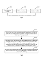
Figure 6 is a flow diagram of a method for performing interference control of an embodiment of the invention. - The inventors find that, in TDD networking, if different cells adopt different uplink and downlink configurations, the influence degree of cross link interference on the performances of a system is closely related with traffic loads of the cells. When the cells are in the medium loads or the relatively heavy loads, the cross link interference can significantly reduce the performances of the system; and when the cells are in the relatively light traffic loads, as the collision probability of traffics in the opposite directions of the adjacent cells is relatively low, that the probability of causing the cross link interference is also relatively low. However, the relatively light traffic loads just refer to a scene that TDD UL-DL subframe dynamic reconfiguration can obtain maximum performance gain. If relatively strict interference control is adopted uniformly, the obtainment of subframe dynamic reconfiguration performance gain will be restricted.
- On this basis, in an embodiment of the invention, for adjacent two cells, a network side device determines an interference control threshold value according to traffic load parameter values of the two cells, compares the measurement parameter value determined with the interference control threshold value, divides the two cells into clusters according to the comparison result and performs interference control according to clusters after dividing. Because the factors of cell traffic loads are considered in the TDD cross link interference control, the cross link interference in the TDD networking is reduced.
- In this case, a radio frame in uplink/downlink configuration involved in the embodiment of the invention includes flexible subframes, fixed downlink subframes, fixed uplink subframes and special subframes. The fixed downlink subframes refer to the subframes with the transmission direction being downlink and fixed, as well as downlink pilot time slots in the special subframe, the uplink fixed subframes refer to the subframes with the transmission direction being uplink and fixed, and the flexible subframes are the subframes with flexible transmission directions. The flexible subframes further include flexible uplink subframes and flexible downlink subframes, wherein the flexible uplink subframes are flexible subframes which are determined for uplink transmission and the flexible downlink subframes are flexible subframes which are determined for downlink transmission.
- Uplink pilot time slots in the special subframes of the embodiment of the invention have the same functions as the uplink pilot time slots in the special subframes in the background and will not be described repeatedly here.
- The embodiment of the invention can be applied to a TDD system (such as a TD-LTE system) and can also be applied to other systems which need to dynamically adjust uplink and downlink configurations of the subframes, for example, a TD-SCDMA system and a subsequent evolution system thereof, a WiMAX (Worldwide Interoperability for Microwave Access) system and the subsequent evolution system thereof and the like.
- In order to support the use of more downlink subframes, only one fixed uplink subframe can be set in one radio frame, namely the
subframe 2 is the fixed uplink subframe, thesubframe 0 and thesubframe 5 are the fixed downlink subframes, thesubframe 1 is the special subframe, thesubframe 6 is the special subframe or the downlink subframe (the subframe with the downlink transmission direction) and the remaining subframes are the flexible subframes;
In this case, when thesubframe 7 is an uplink subframe (namely thesubframe 7 is the flexible subframe with the uplink transmission direction, namely flexible the uplink subframe), thesubframe 6 is the special subframe, such as the structure of the radio frame as shown inFigure 2A ;
When thesubframe 7 is a downlink subframe (namely thesubframe 7 is the flexible subframe with the downlink transmission direction, namely the flexible downlink subframe), thesubframe 6 is a downlink subframe (namely the subframe with the downlink transmission direction), such as the structure of the radio frame as shown inFigure 2B ; and under such frame structure, the maximum proportion, which can be supported, of the downlink (DL) subframes to the uplink (UL) subframes is 9: 1, so that the dynamic range of self-adaptive resource in the dynamic TDD system is larger and traffic changes can be better matched. - An embodiment of the invention provides an uplink and downlink HARQ (Hybrid Automatic Repeat reQuest) temporal relation of a TDD system for the dynamic uplink and downlink subframe distribution as shown in
Figure 2A and Figure 2B . - The measurement parameter value in the embodiment of the invention includes but not limited to one or more of the following parameter values:
- Frequency resource occupancy rate, such as the proportion of PRB resources occupied by traffic transmission in bandwidth of a system in all the PRB resources;
- Time resource occupancy rate, such as the proportion of subframe resources occupied by traffic transmission in the system in all the subframe resources;
- Resource occupancy rate in a specific resource set, such as the resource occupancy rates of the subframes in the fixed direction and the subframes in the flexible direction (as shown in
Figure 2A ), which are respectively counted; and - Statistics of occupancy rates of different traffic types of resources, such as GBR (Guranteed Bit Rate) traffic and Non-GBR traffic which are separately counted.
- In this case, the measurement parameter value between base stations in the embodiment of the invention includes but not limited to one or more of the following parameter values:
- A path loss value, a coupling loss value and an interference power value.
- It should be noted that, as long as the parameter value can represent the isolation degree between the two base stations or signal strength which is received by a certain base station from another base station, it can be used as the measurement parameter value between the base stations in the embodiment of the invention.
- The embodiment of the invention can adopt a centralized interference control mode or a distributed interference control mode. If the centralized interference control mode is adopted, the network side device in the embodiment of the invention is a central node; and if the distributed interference control mode is adopted, the network side device in the embodiment of the invention is the base station.
- When a centralized interference control solution with a center is adopted, traffic load conditions of all the cells are uniformly reported to the central node through a network interface, wherein the central node can be a base station in a network (such as a Macro base station in a macro-pico networking environment or a certain pico base station in a multi-pico networking environment) or a specialized central controller. When a distributed interference control solution without the center is adopted, the traffic load conditions of respective cells are mutually notified through the network interface, wherein the network interface here can be an X2 interface, an S1 interface or other wired interfaces defined according to existing standard, or can be newly defined interfaces, or even include air interfaces through wireless transmission.
- In the case, the X2 interface is an interface between the base stations and can complete user data delivery, the processing of user data and signaling and the like between the base stations. The S1 interface is a logic interface established between a radio access network node and a core network node and can be further specifically divided into a control plane interface (S1-MME) and a user plane interface (S1-U). The S1-MME is the logic interface established between the radio access network node and MME and used for transmitting control plane signaling (as for the specific contents of the signaling, please refer to 3GPP TS36.413). The S1-U is the logic interface established between the radio access network node and SGW and used for transmitting user plane data (as for formats of user plane data packets, please refer to 3GPP TS29.281).
- The embodiments of the invention will be further described in detail in combination with the accompanying drawings of the description.
- As shown in
Figure 3 , a system for performing interference control of an embodiment of the invention includes anetwork side device 10 and abase station 20. - The
network side device 10 is configured to determine a traffic load parameter value of each cell and a measurement parameter value between base stations which serve for any two cells; for the two cells, determine an interference control threshold value according to the traffic load parameter values of the two cells, and compare the measurement parameter value determined with the interference control threshold value and divides the two cells into clusters according to the comparison result; and perform interference control according to clusters after dividing; and
Thebase station 20 is configured to transmit the traffic load parameter value of each cell managed by the base station and the measurement parameter value between the base station and another base station to the network side device. - Preferably, the
network side device 10 determines the load grade according to the traffic load parameter values of the two cells; and searches for the interference control threshold value corresponding to the load grade determined according to the corresponding relation between the load grade and the interference control threshold value and takes the interference control threshold value searched out as the interference control threshold value. - In the implementation, the corresponding relation between the load grade and the interference control threshold value can be set as needed. The traffic load conditions can be divided into more than one grade and the corresponding interference control threshold value is set according to each traffic load condition grade, thereby preventing the uniform setting of the interference control threshold value from limiting the flexibility of the network.
- Assumed that, there are two interference control threshold values, namely P1 and P2, P1<P2, the grade I corresponds to the P1 threshold, and the grade II corresponds to the P2 threshold, when the cell A and the cell B are in the situation of relatively light traffic loads (for example, the traffic load parameter values of both the cell A and the cell B are smaller than the threshold), the load grade is considered to be the grade I and clustering judgment is performed based on the P1 threshold; and when one of the cell A and the cell B is in the situation of relatively heavy traffic load (for example, the traffic load parameter value of the cell A or the cell B is smaller than the threshold), the load grade can be considered to be the grade II and the clustering judgment is performed based on the P2 threshold.
- Preferably, if the measurement parameter value between the base stations is the path loss value or the coupling loss value:
- When the measurement parameter value between the base stations which serves for the two cells is smaller than the determined interference control threshold value, the
network side device 10 divides the two cells into a same cluster; and when the measurement parameter value between the base stations which serves for the two cells is no smaller than the determined interference control threshold value, thenetwork side device 10 divides the two cells into different clusters. - For example, when the cell A and the cell B are in the situation of relatively light traffic loads, the clustering judgment is performed based on the P1 threshold, that is, when P_AB<P1, the cells A and B are divided into the same cluster; otherwise, the cells A and B are divided into the different clusters;
When one of the cell A and the cell B is in the situation of relatively heavy traffic load, the clustering judgment is performed based on the P2 threshold, that is, when P_AB<P2, the cells A and B are divided into the same cluster; otherwise, the cells A and B are divided into different clusters. - Preferably, if the measurement parameter value between the base stations is the interference power value:
- When the measurement parameter value between the base stations which serve for the two cells is larger than the interference control threshold value determined, the
network side device 10 divides the two cells into a same cluster; and - When the measurement parameter value between the base stations which serve for the two cells is no larger than the interference control threshold value determined, the
network side device 10 divides the two cells into the different clusters. - Preferably, after the cluster dividing and before performing the interference control, the
network side device 10 can also perform merging on the clusters after dividing, wherein any two clusters after merging do not contain a same cell. - For example, if the
cluster 1 contains the cells A and B, thecluster 2 contains the cells B and C and thecluster 3 contains the cell D, then thecluster 1 and thecluster 2 are merged into one cluster containing the cells A, B and C, and thecluster 3 is another cluster. - For example, if there are three clusters, the
cluster 1 contains the cells A and B, thecluster 2 contains the cells B and C and thecluster 3 contains the cells C and D, then thecluster 1 and thecluster 2 are merged into onecluster 4 containing the cells A, B and C. As thecluster 3 contains the cell C, thecluster 3 and thecluster 4 can also be merged into one cluster containing the cells A, B, C and D. - Preferably, the
network side device 10 uses same uplink and downlink configurations for the cells in the same cluster; and uses same or different uplink and downlink configurations for the cells in the different clusters. - In the implementation, if the embodiment of the invention adopts the centralized interference control mode, the
network side device 10 is the central node; and if the embodiment of the invention adopts the distributed interference control mode, thenetwork side device 10 is the base station. - Preferably, when the centralized interference control mode with a central node is adopted, the measurement parameter values are reported by the base stations to the central node; and the traffic load parameter values of the TDD cells are reported by the base stations to the central node.
- Specifically, for one base station, the
network side device 10 receives the traffic load parameter value of each cell managed by the base station, which is determined by the base station, and the measurement parameter value between the base station and another base station, which is determined by the base station. - When the distributed interference control mode without the central node is adopted, the measurement parameter values are interacted between the base stations; and the traffic load parameter values of the cells are interacted between the base stations.
- Specifically, the
network side device 10 determines the traffic load parameter value of each cell managed by thenetwork side device 10 and the measurement parameter value between thenetwork side device 10 and another network side device and receives the traffic load parameter value of each cell managed by another base station, which is determined by the another base station, and the measurement parameter value between the base stations, which is determined by the another base station. - For example, the base station A can receive the traffic load parameter value of the cell managed by the base station B and the measurement parameter value between the base station B and another base station, which is determined by the base station B.
- If the distributed interference control mode without the central node is adopted, the
network side device 10 also needs to transmit the traffic load parameter value of the cell managed by thenetwork side device 10 and the measurement parameter value between thenetwork side device 10 and another network side device to another base station. - Taking
Figure 4 as an example, the path loss between the cell A and the cell B is XdB, the path loss between the cell C and the cell D is YdB and X and Y are close. If the cell A and the cell B are in the relatively heavy loads, then the threshold value P1 is used; and if the cell C and the cell D are in the relatively light loads, then the threshold value P2 is used. - According to the solution of the embodiment of the invention, as X<P1, the cell A and the cell B are divided into the same cluster and the same uplink and downlink configurations are used; and as Y≥P2, the cells C and D respectively independently form the clusters and the different uplink and downlink configurations can be used, so that the flexibility in resource scheduling in the traffic range of the cell C and the cell D is further upgraded.
- As the cell E is relatively far relative to the cells A, B, C and D, the path loss between the cell E and each cell is no smaller than P1 and P2 and the cell E can independently form the cluster.
- As shown in
Figure 5 , the network side device in the system for performing interference control of the embodiment of the invention includes: adetermination module 500, adivision module 510 and acontrol module 520. - The
determination module 500 is configured to determine the traffic load parameter value of each cell and the measurement parameter value between the base stations which serve for any two cells belong;
Thedivision module 510 is configured to, for the two cells, determine the interference control threshold value according to the traffic load parameter values of the two cells, compare the measurement parameter value determined with the interference control threshold value and divide the two cells into clusters according to the comparison result; and
Thecontrol module 520 is configured to perform interference control according to the clusters after dividing. - Preferably, the
division module 510 determines the load grade according to the traffic load parameter values of the two cells; and searches for the interference control threshold value corresponding to the load grade determined according to the corresponding relation between the load grade and the interference control threshold value and takes the interference control threshold value searched out as the interference control threshold value. - Preferably, if the measurement parameter value between the base stations is the path loss value or the coupling loss value;
When the measurement parameter value between the base stations which serve for the two cells is smaller than the interference control threshold value determined, thedivision module 510 divides the two cells into a same cluster; and when the measurement parameter value between the base stations which serve for the two cells is no smaller than the interference control threshold value determined, thedivision module 510 divides the two cells into the different clusters. - Preferably, if the measurement parameter value between the base stations is the interference power value;
When the measurement parameter value between the base stations which serves for the two cells is larger than the interference control threshold value determined, thedivision module 510 divides the two cells into the same cluster; and when the measurement parameter value between the base stations which serve for the two cells is no larger than the interference control threshold value determined, thedivision module 510 divides the two cells into the different clusters. - Preferably, after cluster dividing, the
division module 510 performs merging on the clusters after dividing;
In this case, any two clusters after merging do not contain a same cell. - Preferably, the
control module 520 uses same uplink and downlink configurations for the cells in the same cluster; and uses same or different uplink and downlink configurations for the cells in the different clusters. - Preferably, if the centralized interference control mode is adopted, the network side device is the central node; and if the distributed interference control mode is adopted, the network side device is the base station.
- Preferably, the network side device is the central node;
For one base station, thedetermination module 500 receives the traffic load parameter value of each cell managed by the base station, which is determined by the base station, and the measurement parameter value between the base station and another base station, which is determined by the base station. - Preferably, the network side device is the base station;
Thedetermination module 500 determines the traffic load parameter value of each cell managed by the network side device and the measurement parameter value between the network side device and another network side device and receives the traffic load parameter value of each cell managed by another base station, which is determined by the another base station, and the measurement parameter value between the base stations, which is determined by the another base station. - If the distributed interference control mode without the center is adopted, the
determination module 500 also needs to transmit the traffic load parameter value of the cell managed by the network side device and the measurement parameter value between the network side device and another network side device to another base station. - Based on the same inventive concept, an embodiment of the invention further provides a method for performing interference control. As the principle of the method for solving the problems is similar to that of the system for performing interference control of the embodiment of the invention, the implementation of the method can refer to the implementation of the system and will not be repeatedly discussed here.
- As shown in
Figure 6 , the method for performing interference control of the embodiment of the invention includes the following operations: -
Operation 601, a network side device determines a traffic load parameter value of each cell and a measurement parameter value between base stations which serve for any two cells; -
Operation 602, for the two cells, the network side device determines the interference control threshold value according to the traffic load parameter values of the two cells, compares the measurement parameter value determined with the interference control threshold value and divides the two cells into clusters according to the comparison result; and -
Operation 603, the network side device performs interference control according to clusters after dividing. - Preferably, in
operation 602, the network side device determines a load grade according to the traffic load parameter values of the two cells; and searches for the interference control threshold value corresponding to the load grade determined according to the corresponding relation between the load grade and the interference control threshold value and takes the interference control threshold value searched out as the interference control threshold value. - In the implementation, the corresponding relation between the load grade and the interference control threshold value can be set as needed. The traffic load conditions can be divided into more than one grade and the corresponding interference control threshold value is set according to each traffic load condition grade, thereby preventing the uniform setting of the interference control threshold value from limiting the flexibility of the network.
- Preferably, if the measurement parameter value between the base stations is the path loss value or the coupling loss value:
- When the measurement parameter value between the base stations which serve for the two cells is smaller than the interference control threshold value determined, the network side device divides the two cells into a same cluster; and when the measurement parameter value between the base stations which serve for the two cells is no smaller than the interference control threshold value determined, the network side device divides the two cells into different clusters.
- Preferably, if the measurement parameter value between the base stations is the interference power value:
- When the measurement parameter value between the base stations which serve for the two cells is larger than the interference control threshold value determined, the network side device divides the two cells into a same cluster; and
- When the measurement parameter value between the base stations which serve for the two cells is no larger than the interference control threshold value determined, the network side device divides the two cells into the different clusters.
- Preferably, after the cluster dividing and before performing the interference control, the network side device can also perform merging on the clusters after dividing, wherein any two clusters after merging do not contain a same cell.
- Preferably, in
operation 603, the network side device uses same uplink and downlink configurations for the cells in the same cluster; and uses same or different uplink and downlink configurations for the cells in the different clusters. - In the implementation, if the embodiment of the invention adopts the centralized interference control mode, the network side device is the central node; and if the embodiment of the invention adopts the distributed interference control mode, the network side device is the base station.
- Preferably, when the centralized interference control way with a center is adopted, the measurement parameter values are reported by the base stations to the central node; and the traffic load parameter values of the TDD cells are reported by the base stations to the central node.
- Specifically, in
operation 601, for one base station, the network side device receives the traffic load parameter value of each cell managed by the base station, which is determined by the base station, and the measurement parameter value between the base station and another base station, which is determined by the base station. - When the distributed interference control way without the center is adopted, the measurement parameter value is interacted between the base stations; and the traffic load parameter values of the cells are interacted between the base stations.
- Specifically, in
operation 601, the network side device determines the traffic load parameter value of each cell managed by the network side device and the measurement parameter value between the network side device and another network side device and receives the traffic load parameter value of each cell managed by another base station, which is determined by the another base station, and the measurement parameter value between the base stations, which is determined by the another base station. - Those skilled in the art should understand that the embodiments of the invention can provide the method, the system or a computer program product. Therefore, the invention can adopt the forms of complete hardware embodiments, complete software embodiments or embodiments combining software and hardware. Furthermore, the invention can adopt the form of the computer program product which is implemented on one or more computer usable storage media (including but not limited to magnetic disk memories, CD-ROMs, optical memories and the like) containing computer usable program codes.
- The invention is described by referring to a flow diagram and/or a block diagram of the method, the device (system) and the computer program product according to the embodiments of the invention. It should be understood that each process and/or block in the flow diagram and/or the block diagram and the combination of the processes and/or the blocks in the flow diagram and/or the block diagram can be implemented by computer program instructions. These computer program instructions can be provided to a general-purpose computer, a special-purpose computer, an embedded processor or a processor of another programmable data processing device to produce a machine, thereby producing a device for implementing the functions designated in one or multiple processes in the flow diagram and/or one or multiple blocks in the block diagram through the instructions executed by the computer or the processor of the another programmable data processing device.
- These computer program instructions can be stored in a computer readable memory capable of guiding the computer or the another programmable data processing device to work in a specific way, thereby enabling the instructions which are stored in the computer readable memory to produce a manufactured product including an instruction device, wherein the instruction device implements the functions designated in one or multiple processes in the flow diagram and/or one or multiple blocks in the block diagram.
- These computer program instructions can also be loaded onto the computer or the another programmable data processing device, so that the computer or the another programmable device can execute a series of operation operations to produce the treatment implemented by the computer, thereby enabling the instructions executed on the computer or the another programmable device to provide the operation of implementing the functions designated in one or multiple processes in the flow diagram and/or one or multiple blocks in the block diagram.
- Although the preferred embodiments of the invention have been described, once those skilled in the art know the basic inventive concepts, they can make alternative changes and modifications to these embodiments. Thus, the appended claims intend to be interpreted as including the preferred embodiments and all the changes and modifications within the scope of the invention.
- Obviously, those skilled in the art can make various modifications and variations to the invention without deviating from the spirit and scope of the invention. Thus, if the modifications and variations of the invention still fall within the scope of the claims of the invention and the equivalent technologies thereof, the invention also intend to include these modifications and variations.
Claims (23)
- A method for performing interference control, comprising:determining, by a network side device, a traffic load parameter value of each cell and a measurement parameter value between base stations which serve for any two cells;for the two cells, determining, by the network side device, an interference control threshold value according to the traffic load parameter values of the two cells, comparing the measurement parameter value determined with the interference control threshold value and dividing the two cells into clusters according to the comparison result; andperforming, by the network side device, interference control according to clusters after dividing.
- The method according to claim 1, wherein determining, by the network side device, the interference control threshold value comprises:determining, by the network side device, a load grade according to the traffic load parameter values of the two cells; andsearching for, by the network side device, an interference control threshold value corresponding to the load grade determined according to a corresponding relation between the load grade and the interference control threshold value and taking the interference control threshold value searched out as the interference control threshold value.
- The method according to claim 1, wherein the measurement parameter value between the base stations is one or more of the following parameter values:a path loss value, a coupling loss value and an interference power value.
- The method according to claim 3, wherein the measurement parameter value between the base stations is the path loss value or the coupling loss value; then
the dividing, by the network side device, the two cells into clusters comprises:when the measurement parameter value between the base stations which serve for the two cells is smaller than the interference control threshold value determined, dividing, by the network side device, the two cells into a same cluster; andwhen the measurement parameter value between the base stations which serve for the two cells is no smaller than the interference control threshold value determined, dividing, by the network side device, the two cells into different clusters. - The method according to claim 3, wherein the measurement parameter value between the base stations is the interference power value; then
the dividing, by the network side device, the two cells into clusters comprises:when the measurement parameter value between the base stations which serve for the two cells is larger than the interference control threshold value determined, dividing, by the network side device, the two cells into a same cluster; andwhen the measurement parameter value between the base stations which serve for the two cells is no larger than the interference control threshold value determined, dividing, by the network side device, the two cells into different clusters. - The method according to claim 1, wherein after the network side device divides the two cells into clusters and before the network side device performs interference control, the method further comprises:performing, by the network side device, merging on the clusters after dividing;wherein any two clusters after merging do not contain a same cell.
- The method according to any one of claims 1-6, wherein the performing, by the network side device, interference control according to the clusters after dividing comprises:the network side device using same uplink and downlink configurations for the cells in the same cluster; andthe network side device using same or different uplink and downlink configurations for the cells in the different clusters.
- The method according to any one of claims 1-6, wherein if a centralized interference control mode is adopted, the network side device is a central node; and
if a distributed interference control mode is adopted, the network side device is a base station. - The method according to claim 8, wherein the network side device is the central node; and
determining, by the network side device, the traffic load parameter value of each cell and the measurement parameter value between the base stations which serve for any two cells comprises:for one base station, the network side device receives the traffic load parameter value of each cell managed by the base station, which is determined by the base station, and the measurement parameter value between the base station and another base station, which is determined by the base station. - The method according to claim 8, wherein the network side device is the base station;
determining, by the network side device, the traffic load parameter value of each cell and the measurement parameter value between the base stations which serve for any two cells comprises:determining, by the network side device, the traffic load parameter value of each cell managed by the network side device and the measurement parameter value between the network side device and another network side device, and receiving the traffic load parameter value of each cell managed by another base station, which is determined by the another base station, and the measurement parameter value between the base stations, which is determined by the another base station. - The method according to any one of claims 1-6, wherein the traffic load parameter value of each cell comprises one or more of the following parameter values:frequency resource occupancy rate, time resource occupancy rate, resource occupancy rate in a specific resource set and statistics of occupancy rates of different traffic types of resources.
- A network side device for performing interference control, comprising:a determination module configured to determine a traffic load parameter value of each cell and a measurement parameter value between base stations which serve for any two cells;a division module configured to, for the two cells, determine an interference control threshold value according to the traffic load parameter values of the two cells, compare the measurement parameter value determined with the interference control threshold value and divide the two cells into clusters according to the comparison result; anda control module configured to perform interference control according to clusters after dividing.
- The network side device according to claim 12, wherein the division module is specifically configured to:determine a load grade according to the traffic load parameter values of the two cells; and search for an interference control threshold value corresponding to the load grade determined according to a corresponding relation between the load grade and the interference control threshold value and take the interference control threshold value searched out as the interference control threshold value.
- The network side device according to claim 12, wherein the measurement parameter value between the base stations is one or more of the following parameter values:a path loss value, a coupling loss value and an interference power value.
- The network side device according to claim 14, wherein the measurement parameter value between the base stations is the path loss value or the coupling loss value;
and the division module is specifically configured to:when the measurement parameter value between the base stations which serve for the two cells is smaller than the interference control threshold value determined, divide the two cells into a same cluster; and when the measurement parameter value between the base stations which serve for the two cells is no smaller than the interference control threshold value determined, divide the two cells into different clusters. - The network side device according to claim 14, wherein the measurement parameter value between the base stations is the interference power value;
and the division module is specifically configured to:when the measurement parameter value between the base stations which serve for the two cells is larger than the interference control threshold value determined, divide the two cells into a same cluster; and when the measurement parameter value between the base stations which serve for the two cells is no larger than the interference control threshold value determined, divide the two cells into different clusters. - The network side device according to claim 12, wherein the division module is further configured to:perform merging on the clusters after dividing,wherein any two clusters after merging do not contain a same cell.
- The network side device according to any one of claims 12-17, wherein the control module is specifically configured to:use same uplink and downlink configurations for the cells in the same cluster; and use same or different uplink and downlink configurations for the cells in the different clusters.
- The network side device according to any one of claims 12-17, wherein if a centralized interference control mode is adopted, the network side device is a central node; and
if a distributed interference control mode is adopted, the network side device is a base station. - The network side device according to claim 19, wherein the network side device is the central node; and
the determination module is specifically configured to:for one base station, receive the traffic load parameter value of each cell managed by the base station, which is determined by the base station, and the measurement parameter value between the base station and another base station, which is determined by the base station. - The network side device according to claim 19, wherein the network side device is the base station; and
the determination module is specifically configured to:determine the traffic load parameter value of each cell managed by the network side device and the measurement parameter value between the network side device and another network side device, and receive the traffic load parameter value of each cell managed by another base station, which is determined by the another base station, and the measurement parameter value between the base stations, which is determined by the another base station. - The network side device according to any one of claims 12-17, wherein the traffic load parameter value of each cell comprises one or more of the following parameter values:frequency resource occupancy rate, time resource occupancy rate, resource occupancy rate in a specific resource set and statistics of occupancy rates of different traffic types of resources.
- A system for performing interference control, comprising:a network side device configured to determine a traffic load parameter value of each cell and a measurement parameter value between base stations which serve for any two cells; for the two cells, determine an interference control threshold value according to the traffic load parameter values of the two cells, compare the measurement parameter value determined with the interference control threshold value and divide the two cells into clusters according to the comparison result; and perform interference control according to clusters after dividing; anda base station configured to transmit the traffic load parameter value of each cell managed by the base station and the measurement parameter value between the base station and another base station to the network side device.
Applications Claiming Priority (2)
| Application Number | Priority Date | Filing Date | Title |
|---|---|---|---|
| CN201210127618.5A CN103379520B (en) | 2012-04-26 | 2012-04-26 | A kind of carrying out disturbs the method and apparatus controlled |
| PCT/CN2013/072172 WO2013159598A1 (en) | 2012-04-26 | 2013-03-05 | Method and device for performing interference control |
Publications (3)
| Publication Number | Publication Date |
|---|---|
| EP2843987A1 true EP2843987A1 (en) | 2015-03-04 |
| EP2843987A4 EP2843987A4 (en) | 2015-10-28 |
| EP2843987B1 EP2843987B1 (en) | 2017-05-10 |
Family
ID=49463969
Family Applications (1)
| Application Number | Title | Priority Date | Filing Date |
|---|---|---|---|
| EP13782052.8A Active EP2843987B1 (en) | 2012-04-26 | 2013-03-05 | Method and device for performing interference control |
Country Status (4)
| Country | Link |
|---|---|
| US (1) | US9775056B2 (en) |
| EP (1) | EP2843987B1 (en) |
| CN (1) | CN103379520B (en) |
| WO (1) | WO2013159598A1 (en) |
Cited By (2)
| Publication number | Priority date | Publication date | Assignee | Title |
|---|---|---|---|---|
| EP3116256A1 (en) * | 2015-07-07 | 2017-01-11 | Vodafone IP Licensing limited | Device for controlling network resources |
| WO2018202956A1 (en) * | 2017-05-05 | 2018-11-08 | Nokia Solutions And Networks Oy | Enabling exchange of information on radio frame configuration in neighbor cells |
Families Citing this family (20)
| Publication number | Priority date | Publication date | Assignee | Title |
|---|---|---|---|---|
| CN104066093B (en) * | 2013-03-18 | 2018-03-23 | 财团法人工业技术研究院 | Interference management method, anchor point equipment, base station and system of wireless communication system |
| WO2014166067A1 (en) * | 2013-04-09 | 2014-10-16 | Qualcomm Incorporated | Dynamic cell cluster interference management scheme using dynamic point selection (dps) or semi-static point selection (spss) for enhanced interference management and traffic adaptation (eimta) |
| US9906350B2 (en) * | 2013-05-08 | 2018-02-27 | Acer Incorporated | Method of handling interference mitigation and related communication device |
| WO2015089745A1 (en) * | 2013-12-17 | 2015-06-25 | 华为技术有限公司 | Method and network device for obtaining and configuring sub-frame structure |
| US10009861B2 (en) * | 2014-10-14 | 2018-06-26 | Qualcomm Incorporated | Techniques for adaptively enabling synchronization of nodes using a listen before talk load-based equipment protocol |
| US10149293B2 (en) * | 2014-10-16 | 2018-12-04 | Qualcomm Incorporated | Transmission preemption for enhanced component carriers |
| EP3016309B1 (en) * | 2014-10-28 | 2017-10-18 | Alcatel Lucent | Apparatus and method for full-duplex communication over a shared transmission medium |
| WO2016127394A1 (en) * | 2015-02-13 | 2016-08-18 | 华为技术有限公司 | Method and apparatus for controlling interference, and communication system |
| WO2017113215A1 (en) * | 2015-12-30 | 2017-07-06 | 华为技术有限公司 | Method and apparatus for merging cells |
| WO2017113217A1 (en) * | 2015-12-30 | 2017-07-06 | 华为技术有限公司 | Cell merging/splitting method and apparatus |
| EP3280177B1 (en) * | 2016-08-01 | 2019-05-22 | Alcatel Lucent | Control method and control system for controlling access points in a wireless network |
| CN110024462A (en) * | 2017-01-06 | 2019-07-16 | 富士通株式会社 | Transmitting device, method and communication system based on dynamic Time Division duplex |
| CN110637494A (en) * | 2017-06-09 | 2019-12-31 | 中兴通讯股份有限公司 | Systems and methods for measuring and controlling cross-link interference in wireless communications |
| TWI693809B (en) * | 2017-06-16 | 2020-05-11 | 聯發科技股份有限公司 | Method and apparatus for cross-link interference measurement in mobile communications |
| US11343064B2 (en) * | 2018-05-03 | 2022-05-24 | Samsung Electronics Co., Ltd. | Systems and methods to improve co-existence between fixed wireless access and short range devices in 802.11ay |
| CN108934030B (en) * | 2018-07-19 | 2021-08-03 | 中信科移动通信技术股份有限公司 | Method for avoiding cross interference of IAB base station |
| US12035345B2 (en) | 2019-01-23 | 2024-07-09 | Apple Inc. | Data channel mapping type and DM-RS configuration to enable L1 CLI measurement and reporting |
| CN110662302B (en) * | 2019-09-02 | 2022-05-06 | 普联技术有限公司 | RU subchannel allocation method, device, storage medium and network equipment |
| WO2023123096A1 (en) * | 2021-12-29 | 2023-07-06 | 北京小米移动软件有限公司 | Interference coordination method, apparatus, and storage medium |
| CN116419264A (en) * | 2021-12-30 | 2023-07-11 | 中兴通讯股份有限公司 | Frame structure adjustment method, device, electronic device and storage medium |
Family Cites Families (10)
| Publication number | Priority date | Publication date | Assignee | Title |
|---|---|---|---|---|
| US5497503A (en) * | 1993-05-28 | 1996-03-05 | Ameritech Corporation | Method for assigning frequency channels in a cellular communication system and for identifying critical existing fixed microwave receivers that restrict operation of such a system |
| CN1564483A (en) | 2004-04-07 | 2005-01-12 | 中兴通讯股份有限公司 | Dynamic channel distributing method of TD-SCDMA |
| WO2006069489A1 (en) * | 2004-12-31 | 2006-07-06 | Utstarcom Telecom Co., Ltd. | Method and base station for uplink timeslot assignment in utra tdd system |
| CN1929323B (en) * | 2005-09-07 | 2011-04-06 | 大唐移动通信设备有限公司 | Method of suppressing cross time slot interfere for time slot CDMA system |
| CN101459956B (en) * | 2007-12-10 | 2012-01-11 | 电信科学技术研究院 | Load control method and apparatus |
| CN101291515B (en) | 2008-06-06 | 2010-12-08 | 北京邮电大学 | A method for interference suppression in wireless communication system |
| US8285298B2 (en) * | 2009-12-23 | 2012-10-09 | At&T Mobility Ii Llc | Chromatic scheduler for network traffic with disparate service requirements |
| EP2437536B1 (en) * | 2010-09-29 | 2018-04-25 | Alcatel Lucent | Method and device to manage cells in a cellular network |
| CN102036295B (en) * | 2010-12-02 | 2014-04-16 | 大唐移动通信设备有限公司 | Method, system and equipment for determining uplink and downlink configuration |
| CN102291785B (en) * | 2011-09-21 | 2014-08-20 | 电信科学技术研究院 | Method and equipment for resource coordination between cells |
-
2012
- 2012-04-26 CN CN201210127618.5A patent/CN103379520B/en active Active
-
2013
- 2013-03-05 EP EP13782052.8A patent/EP2843987B1/en active Active
- 2013-03-05 WO PCT/CN2013/072172 patent/WO2013159598A1/en not_active Ceased
- 2013-03-05 US US14/397,198 patent/US9775056B2/en active Active
Cited By (3)
| Publication number | Priority date | Publication date | Assignee | Title |
|---|---|---|---|---|
| EP3116256A1 (en) * | 2015-07-07 | 2017-01-11 | Vodafone IP Licensing limited | Device for controlling network resources |
| WO2018202956A1 (en) * | 2017-05-05 | 2018-11-08 | Nokia Solutions And Networks Oy | Enabling exchange of information on radio frame configuration in neighbor cells |
| US11350405B2 (en) | 2017-05-05 | 2022-05-31 | Nokia Solutions And Networks Oy | Enabling exchange of information on radio frame configuration in neighbor cells |
Also Published As
| Publication number | Publication date |
|---|---|
| EP2843987B1 (en) | 2017-05-10 |
| CN103379520B (en) | 2016-02-17 |
| CN103379520A (en) | 2013-10-30 |
| WO2013159598A1 (en) | 2013-10-31 |
| EP2843987A4 (en) | 2015-10-28 |
| US9775056B2 (en) | 2017-09-26 |
| US20150045076A1 (en) | 2015-02-12 |
Similar Documents
| Publication | Publication Date | Title |
|---|---|---|
| US9775056B2 (en) | Method and device for performing interference control | |
| US10798723B2 (en) | Vehicle to everything communication control method and apparatus therefor | |
| US10021654B2 (en) | Method for controlling power and apparatus therefor in wireless communication system supporting device-to-device communication | |
| CN102026209B (en) | Method, system and device for transmitting information and configuring subframes | |
| US9854600B2 (en) | Method for controlling transmission of uplink control information on plurality of serving cells, and apparatus therefor | |
| CN105210403B (en) | Method for enhancing small cell | |
| CN102281638B (en) | Method and equipment for scheduling slot | |
| US20140126501A1 (en) | Method and device for inter-cell interference coordination | |
| EP3089531B1 (en) | User terminal and radio communication method | |
| KR20200018468A (en) | Full duplex downlink and uplink direction | |
| US9538543B2 (en) | Interference indicator for wireless communication systems | |
| US20150117348A1 (en) | Communication control device, communication control method, and terminal device | |
| CN102036295A (en) | Method, system and equipment for determining uplink and downlink configuration | |
| WO2013051350A1 (en) | Wireless communication apparatus, wireless communication method, and wireless communication system | |
| CN102137499B (en) | Method, system and equipment for performing interruption coordination | |
| EP3193552B1 (en) | Device-to-device communication method and apparatus | |
| CN103906244A (en) | Method, system and device for information transmission | |
| EP4062694B1 (en) | Group rnti update at beam change | |
| CN103391168B (en) | A kind of method and device carrying out interference control | |
| JP2021503774A (en) | Techniques and equipment for carrier management | |
| CN106165484B (en) | Method, device and communication system for controlling interference | |
| US20260032685A1 (en) | Communication method and apparatus | |
| KR20160094876A (en) | Method and apparatus for transmitting and receiving reference signal using unlicensed band | |
| CN104038943A (en) | Interference coordination method, interference coordination system and network node | |
| CN103687007A (en) | Informing and receiving method and device of slot assignment information |
Legal Events
| Date | Code | Title | Description |
|---|---|---|---|
| PUAI | Public reference made under article 153(3) epc to a published international application that has entered the european phase |
Free format text: ORIGINAL CODE: 0009012 |
|
| 17P | Request for examination filed |
Effective date: 20141118 |
|
| AK | Designated contracting states |
Kind code of ref document: A1 Designated state(s): AL AT BE BG CH CY CZ DE DK EE ES FI FR GB GR HR HU IE IS IT LI LT LU LV MC MK MT NL NO PL PT RO RS SE SI SK SM TR |
|
| AX | Request for extension of the european patent |
Extension state: BA ME |
|
| DAX | Request for extension of the european patent (deleted) | ||
| RA4 | Supplementary search report drawn up and despatched (corrected) |
Effective date: 20150930 |
|
| RIC1 | Information provided on ipc code assigned before grant |
Ipc: H04W 24/02 20090101AFI20150924BHEP Ipc: H04W 16/10 20090101ALI20150924BHEP |
|
| GRAP | Despatch of communication of intention to grant a patent |
Free format text: ORIGINAL CODE: EPIDOSNIGR1 |
|
| INTG | Intention to grant announced |
Effective date: 20161026 |
|
| GRAS | Grant fee paid |
Free format text: ORIGINAL CODE: EPIDOSNIGR3 |
|
| STAA | Information on the status of an ep patent application or granted ep patent |
Free format text: STATUS: GRANT OF PATENT IS INTENDED |
|
| GRAA | (expected) grant |
Free format text: ORIGINAL CODE: 0009210 |
|
| STAA | Information on the status of an ep patent application or granted ep patent |
Free format text: STATUS: THE PATENT HAS BEEN GRANTED |
|
| AK | Designated contracting states |
Kind code of ref document: B1 Designated state(s): AL AT BE BG CH CY CZ DE DK EE ES FI FR GB GR HR HU IE IS IT LI LT LU LV MC MK MT NL NO PL PT RO RS SE SI SK SM TR |
|
| REG | Reference to a national code |
Ref country code: GB Ref legal event code: FG4D |
|
| REG | Reference to a national code |
Ref country code: AT Ref legal event code: REF Ref document number: 893495 Country of ref document: AT Kind code of ref document: T Effective date: 20170515 Ref country code: CH Ref legal event code: EP |
|
| REG | Reference to a national code |
Ref country code: IE Ref legal event code: FG4D |
|
| REG | Reference to a national code |
Ref country code: DE Ref legal event code: R096 Ref document number: 602013021020 Country of ref document: DE |
|
| REG | Reference to a national code |
Ref country code: NL Ref legal event code: MP Effective date: 20170510 |
|
| REG | Reference to a national code |
Ref country code: LT Ref legal event code: MG4D |
|
| REG | Reference to a national code |
Ref country code: AT Ref legal event code: MK05 Ref document number: 893495 Country of ref document: AT Kind code of ref document: T Effective date: 20170510 |
|
| PG25 | Lapsed in a contracting state [announced via postgrant information from national office to epo] |
Ref country code: AT Free format text: LAPSE BECAUSE OF FAILURE TO SUBMIT A TRANSLATION OF THE DESCRIPTION OR TO PAY THE FEE WITHIN THE PRESCRIBED TIME-LIMIT Effective date: 20170510 Ref country code: NO Free format text: LAPSE BECAUSE OF FAILURE TO SUBMIT A TRANSLATION OF THE DESCRIPTION OR TO PAY THE FEE WITHIN THE PRESCRIBED TIME-LIMIT Effective date: 20170810 Ref country code: ES Free format text: LAPSE BECAUSE OF FAILURE TO SUBMIT A TRANSLATION OF THE DESCRIPTION OR TO PAY THE FEE WITHIN THE PRESCRIBED TIME-LIMIT Effective date: 20170510 Ref country code: LT Free format text: LAPSE BECAUSE OF FAILURE TO SUBMIT A TRANSLATION OF THE DESCRIPTION OR TO PAY THE FEE WITHIN THE PRESCRIBED TIME-LIMIT Effective date: 20170510 Ref country code: FI Free format text: LAPSE BECAUSE OF FAILURE TO SUBMIT A TRANSLATION OF THE DESCRIPTION OR TO PAY THE FEE WITHIN THE PRESCRIBED TIME-LIMIT Effective date: 20170510 Ref country code: GR Free format text: LAPSE BECAUSE OF FAILURE TO SUBMIT A TRANSLATION OF THE DESCRIPTION OR TO PAY THE FEE WITHIN THE PRESCRIBED TIME-LIMIT Effective date: 20170811 Ref country code: HR Free format text: LAPSE BECAUSE OF FAILURE TO SUBMIT A TRANSLATION OF THE DESCRIPTION OR TO PAY THE FEE WITHIN THE PRESCRIBED TIME-LIMIT Effective date: 20170510 |
|
| PG25 | Lapsed in a contracting state [announced via postgrant information from national office to epo] |
Ref country code: NL Free format text: LAPSE BECAUSE OF FAILURE TO SUBMIT A TRANSLATION OF THE DESCRIPTION OR TO PAY THE FEE WITHIN THE PRESCRIBED TIME-LIMIT Effective date: 20170510 Ref country code: IS Free format text: LAPSE BECAUSE OF FAILURE TO SUBMIT A TRANSLATION OF THE DESCRIPTION OR TO PAY THE FEE WITHIN THE PRESCRIBED TIME-LIMIT Effective date: 20170910 Ref country code: PL Free format text: LAPSE BECAUSE OF FAILURE TO SUBMIT A TRANSLATION OF THE DESCRIPTION OR TO PAY THE FEE WITHIN THE PRESCRIBED TIME-LIMIT Effective date: 20170510 Ref country code: LV Free format text: LAPSE BECAUSE OF FAILURE TO SUBMIT A TRANSLATION OF THE DESCRIPTION OR TO PAY THE FEE WITHIN THE PRESCRIBED TIME-LIMIT Effective date: 20170510 Ref country code: RS Free format text: LAPSE BECAUSE OF FAILURE TO SUBMIT A TRANSLATION OF THE DESCRIPTION OR TO PAY THE FEE WITHIN THE PRESCRIBED TIME-LIMIT Effective date: 20170510 Ref country code: SE Free format text: LAPSE BECAUSE OF FAILURE TO SUBMIT A TRANSLATION OF THE DESCRIPTION OR TO PAY THE FEE WITHIN THE PRESCRIBED TIME-LIMIT Effective date: 20170510 Ref country code: BG Free format text: LAPSE BECAUSE OF FAILURE TO SUBMIT A TRANSLATION OF THE DESCRIPTION OR TO PAY THE FEE WITHIN THE PRESCRIBED TIME-LIMIT Effective date: 20170810 |
|
| PG25 | Lapsed in a contracting state [announced via postgrant information from national office to epo] |
Ref country code: EE Free format text: LAPSE BECAUSE OF FAILURE TO SUBMIT A TRANSLATION OF THE DESCRIPTION OR TO PAY THE FEE WITHIN THE PRESCRIBED TIME-LIMIT Effective date: 20170510 Ref country code: DK Free format text: LAPSE BECAUSE OF FAILURE TO SUBMIT A TRANSLATION OF THE DESCRIPTION OR TO PAY THE FEE WITHIN THE PRESCRIBED TIME-LIMIT Effective date: 20170510 Ref country code: CZ Free format text: LAPSE BECAUSE OF FAILURE TO SUBMIT A TRANSLATION OF THE DESCRIPTION OR TO PAY THE FEE WITHIN THE PRESCRIBED TIME-LIMIT Effective date: 20170510 Ref country code: SK Free format text: LAPSE BECAUSE OF FAILURE TO SUBMIT A TRANSLATION OF THE DESCRIPTION OR TO PAY THE FEE WITHIN THE PRESCRIBED TIME-LIMIT Effective date: 20170510 Ref country code: RO Free format text: LAPSE BECAUSE OF FAILURE TO SUBMIT A TRANSLATION OF THE DESCRIPTION OR TO PAY THE FEE WITHIN THE PRESCRIBED TIME-LIMIT Effective date: 20170510 |
|
| REG | Reference to a national code |
Ref country code: DE Ref legal event code: R097 Ref document number: 602013021020 Country of ref document: DE |
|
| PG25 | Lapsed in a contracting state [announced via postgrant information from national office to epo] |
Ref country code: IT Free format text: LAPSE BECAUSE OF FAILURE TO SUBMIT A TRANSLATION OF THE DESCRIPTION OR TO PAY THE FEE WITHIN THE PRESCRIBED TIME-LIMIT Effective date: 20170510 Ref country code: SM Free format text: LAPSE BECAUSE OF FAILURE TO SUBMIT A TRANSLATION OF THE DESCRIPTION OR TO PAY THE FEE WITHIN THE PRESCRIBED TIME-LIMIT Effective date: 20170510 |
|
| PLBE | No opposition filed within time limit |
Free format text: ORIGINAL CODE: 0009261 |
|
| STAA | Information on the status of an ep patent application or granted ep patent |
Free format text: STATUS: NO OPPOSITION FILED WITHIN TIME LIMIT |
|
| REG | Reference to a national code |
Ref country code: FR Ref legal event code: PLFP Year of fee payment: 6 |
|
| 26N | No opposition filed |
Effective date: 20180213 |
|
| PG25 | Lapsed in a contracting state [announced via postgrant information from national office to epo] |
Ref country code: SI Free format text: LAPSE BECAUSE OF FAILURE TO SUBMIT A TRANSLATION OF THE DESCRIPTION OR TO PAY THE FEE WITHIN THE PRESCRIBED TIME-LIMIT Effective date: 20170510 |
|
| REG | Reference to a national code |
Ref country code: CH Ref legal event code: PL |
|
| PG25 | Lapsed in a contracting state [announced via postgrant information from national office to epo] |
Ref country code: MC Free format text: LAPSE BECAUSE OF FAILURE TO SUBMIT A TRANSLATION OF THE DESCRIPTION OR TO PAY THE FEE WITHIN THE PRESCRIBED TIME-LIMIT Effective date: 20170510 |
|
| REG | Reference to a national code |
Ref country code: BE Ref legal event code: MM Effective date: 20180331 |
|
| REG | Reference to a national code |
Ref country code: IE Ref legal event code: MM4A |
|
| PG25 | Lapsed in a contracting state [announced via postgrant information from national office to epo] |
Ref country code: LU Free format text: LAPSE BECAUSE OF NON-PAYMENT OF DUE FEES Effective date: 20180305 |
|
| PG25 | Lapsed in a contracting state [announced via postgrant information from national office to epo] |
Ref country code: IE Free format text: LAPSE BECAUSE OF NON-PAYMENT OF DUE FEES Effective date: 20180305 |
|
| PG25 | Lapsed in a contracting state [announced via postgrant information from national office to epo] |
Ref country code: BE Free format text: LAPSE BECAUSE OF NON-PAYMENT OF DUE FEES Effective date: 20180331 Ref country code: LI Free format text: LAPSE BECAUSE OF NON-PAYMENT OF DUE FEES Effective date: 20180331 Ref country code: CH Free format text: LAPSE BECAUSE OF NON-PAYMENT OF DUE FEES Effective date: 20180331 |
|
| PG25 | Lapsed in a contracting state [announced via postgrant information from national office to epo] |
Ref country code: MT Free format text: LAPSE BECAUSE OF NON-PAYMENT OF DUE FEES Effective date: 20180305 |
|
| PG25 | Lapsed in a contracting state [announced via postgrant information from national office to epo] |
Ref country code: TR Free format text: LAPSE BECAUSE OF FAILURE TO SUBMIT A TRANSLATION OF THE DESCRIPTION OR TO PAY THE FEE WITHIN THE PRESCRIBED TIME-LIMIT Effective date: 20170510 |
|
| PG25 | Lapsed in a contracting state [announced via postgrant information from national office to epo] |
Ref country code: PT Free format text: LAPSE BECAUSE OF FAILURE TO SUBMIT A TRANSLATION OF THE DESCRIPTION OR TO PAY THE FEE WITHIN THE PRESCRIBED TIME-LIMIT Effective date: 20170510 |
|
| PG25 | Lapsed in a contracting state [announced via postgrant information from national office to epo] |
Ref country code: HU Free format text: LAPSE BECAUSE OF FAILURE TO SUBMIT A TRANSLATION OF THE DESCRIPTION OR TO PAY THE FEE WITHIN THE PRESCRIBED TIME-LIMIT; INVALID AB INITIO Effective date: 20130305 Ref country code: CY Free format text: LAPSE BECAUSE OF FAILURE TO SUBMIT A TRANSLATION OF THE DESCRIPTION OR TO PAY THE FEE WITHIN THE PRESCRIBED TIME-LIMIT Effective date: 20170510 Ref country code: MK Free format text: LAPSE BECAUSE OF NON-PAYMENT OF DUE FEES Effective date: 20170510 |
|
| PG25 | Lapsed in a contracting state [announced via postgrant information from national office to epo] |
Ref country code: AL Free format text: LAPSE BECAUSE OF FAILURE TO SUBMIT A TRANSLATION OF THE DESCRIPTION OR TO PAY THE FEE WITHIN THE PRESCRIBED TIME-LIMIT Effective date: 20170510 |
|
| REG | Reference to a national code |
Ref country code: DE Ref legal event code: R081 Ref document number: 602013021020 Country of ref document: DE Owner name: DATANG MOBILE COMMUNICATIONS EQUIPMENT CO., LT, CN Free format text: FORMER OWNER: CHINA ACADEMY OF TELECOMMUNICATIONS TECHNOLOGY, BEIJING, CN |
|
| REG | Reference to a national code |
Ref country code: GB Ref legal event code: 732E Free format text: REGISTERED BETWEEN 20211007 AND 20211013 |
|
| PGFP | Annual fee paid to national office [announced via postgrant information from national office to epo] |
Ref country code: DE Payment date: 20250319 Year of fee payment: 13 |
|
| PGFP | Annual fee paid to national office [announced via postgrant information from national office to epo] |
Ref country code: FR Payment date: 20250325 Year of fee payment: 13 |
|
| PGFP | Annual fee paid to national office [announced via postgrant information from national office to epo] |
Ref country code: GB Payment date: 20250321 Year of fee payment: 13 |