EP2843927A1 - Image forming system, image forming apparatus, and non-transitory computer readable recording medium storing a setup program - Google Patents
Image forming system, image forming apparatus, and non-transitory computer readable recording medium storing a setup program Download PDFInfo
- Publication number
- EP2843927A1 EP2843927A1 EP20140002880 EP14002880A EP2843927A1 EP 2843927 A1 EP2843927 A1 EP 2843927A1 EP 20140002880 EP20140002880 EP 20140002880 EP 14002880 A EP14002880 A EP 14002880A EP 2843927 A1 EP2843927 A1 EP 2843927A1
- Authority
- EP
- European Patent Office
- Prior art keywords
- image forming
- user terminal
- identification code
- terminal apparatus
- forming apparatus
- Prior art date
- Legal status (The legal status is an assumption and is not a legal conclusion. Google has not performed a legal analysis and makes no representation as to the accuracy of the status listed.)
- Granted
Links
Images



Classifications
-
- H—ELECTRICITY
- H04—ELECTRIC COMMUNICATION TECHNIQUE
- H04L—TRANSMISSION OF DIGITAL INFORMATION, e.g. TELEGRAPHIC COMMUNICATION
- H04L67/00—Network arrangements or protocols for supporting network services or applications
- H04L67/34—Network arrangements or protocols for supporting network services or applications involving the movement of software or configuration parameters
-
- H—ELECTRICITY
- H04—ELECTRIC COMMUNICATION TECHNIQUE
- H04N—PICTORIAL COMMUNICATION, e.g. TELEVISION
- H04N1/00—Scanning, transmission or reproduction of documents or the like, e.g. facsimile transmission; Details thereof
- H04N1/00962—Input arrangements for operating instructions or parameters, e.g. updating internal software
- H04N1/00973—Input arrangements for operating instructions or parameters, e.g. updating internal software from a remote device, e.g. receiving via the internet instructions input to a computer terminal
-
- G—PHYSICS
- G06—COMPUTING OR CALCULATING; COUNTING
- G06F—ELECTRIC DIGITAL DATA PROCESSING
- G06F3/00—Input arrangements for transferring data to be processed into a form capable of being handled by the computer; Output arrangements for transferring data from processing unit to output unit, e.g. interface arrangements
- G06F3/12—Digital output to print unit, e.g. line printer, chain printer
- G06F3/1201—Dedicated interfaces to print systems
- G06F3/1202—Dedicated interfaces to print systems specifically adapted to achieve a particular effect
- G06F3/1203—Improving or facilitating administration, e.g. print management
- G06F3/1204—Improving or facilitating administration, e.g. print management resulting in reduced user or operator actions, e.g. presetting, automatic actions, using hardware token storing data
-
- G—PHYSICS
- G06—COMPUTING OR CALCULATING; COUNTING
- G06F—ELECTRIC DIGITAL DATA PROCESSING
- G06F3/00—Input arrangements for transferring data to be processed into a form capable of being handled by the computer; Output arrangements for transferring data from processing unit to output unit, e.g. interface arrangements
- G06F3/12—Digital output to print unit, e.g. line printer, chain printer
- G06F3/1201—Dedicated interfaces to print systems
- G06F3/1223—Dedicated interfaces to print systems specifically adapted to use a particular technique
- G06F3/1229—Printer resources management or printer maintenance, e.g. device status, power levels
- G06F3/1232—Transmitting printer device capabilities, e.g. upon request or periodically
-
- G—PHYSICS
- G06—COMPUTING OR CALCULATING; COUNTING
- G06F—ELECTRIC DIGITAL DATA PROCESSING
- G06F3/00—Input arrangements for transferring data to be processed into a form capable of being handled by the computer; Output arrangements for transferring data from processing unit to output unit, e.g. interface arrangements
- G06F3/12—Digital output to print unit, e.g. line printer, chain printer
- G06F3/1201—Dedicated interfaces to print systems
- G06F3/1223—Dedicated interfaces to print systems specifically adapted to use a particular technique
- G06F3/1237—Print job management
- G06F3/1253—Configuration of print job parameters, e.g. using UI at the client
- G06F3/1254—Automatic configuration, e.g. by driver
-
- G—PHYSICS
- G06—COMPUTING OR CALCULATING; COUNTING
- G06F—ELECTRIC DIGITAL DATA PROCESSING
- G06F3/00—Input arrangements for transferring data to be processed into a form capable of being handled by the computer; Output arrangements for transferring data from processing unit to output unit, e.g. interface arrangements
- G06F3/12—Digital output to print unit, e.g. line printer, chain printer
- G06F3/1201—Dedicated interfaces to print systems
- G06F3/1278—Dedicated interfaces to print systems specifically adapted to adopt a particular infrastructure
- G06F3/1285—Remote printer device, e.g. being remote from client or server
-
- G—PHYSICS
- G06—COMPUTING OR CALCULATING; COUNTING
- G06F—ELECTRIC DIGITAL DATA PROCESSING
- G06F9/00—Arrangements for program control, e.g. control units
- G06F9/06—Arrangements for program control, e.g. control units using stored programs, i.e. using an internal store of processing equipment to receive or retain programs
- G06F9/44—Arrangements for executing specific programs
- G06F9/445—Program loading or initiating
- G06F9/44505—Configuring for program initiating, e.g. using registry, configuration files
-
- H—ELECTRICITY
- H04—ELECTRIC COMMUNICATION TECHNIQUE
- H04L—TRANSMISSION OF DIGITAL INFORMATION, e.g. TELEGRAPHIC COMMUNICATION
- H04L12/00—Data switching networks
- H04L12/28—Data switching networks characterised by path configuration, e.g. LAN [Local Area Networks] or WAN [Wide Area Networks]
- H04L12/2803—Home automation networks
- H04L12/2807—Exchanging configuration information on appliance services in a home automation network
- H04L12/2809—Exchanging configuration information on appliance services in a home automation network indicating that an appliance service is present in a home automation network
-
- H—ELECTRICITY
- H04—ELECTRIC COMMUNICATION TECHNIQUE
- H04N—PICTORIAL COMMUNICATION, e.g. TELEVISION
- H04N1/00—Scanning, transmission or reproduction of documents or the like, e.g. facsimile transmission; Details thereof
- H04N1/00127—Connection or combination of a still picture apparatus with another apparatus, e.g. for storage, processing or transmission of still picture signals or of information associated with a still picture
-
- H—ELECTRICITY
- H04—ELECTRIC COMMUNICATION TECHNIQUE
- H04N—PICTORIAL COMMUNICATION, e.g. TELEVISION
- H04N1/00—Scanning, transmission or reproduction of documents or the like, e.g. facsimile transmission; Details thereof
- H04N1/00127—Connection or combination of a still picture apparatus with another apparatus, e.g. for storage, processing or transmission of still picture signals or of information associated with a still picture
- H04N1/00204—Connection or combination of a still picture apparatus with another apparatus, e.g. for storage, processing or transmission of still picture signals or of information associated with a still picture with a digital computer or a digital computer system, e.g. an internet server
-
- H—ELECTRICITY
- H04—ELECTRIC COMMUNICATION TECHNIQUE
- H04N—PICTORIAL COMMUNICATION, e.g. TELEVISION
- H04N1/00—Scanning, transmission or reproduction of documents or the like, e.g. facsimile transmission; Details thereof
- H04N1/0035—User-machine interface; Control console
- H04N1/00405—Output means
- H04N1/00408—Display of information to the user, e.g. menus
- H04N1/00411—Display of information to the user, e.g. menus the display also being used for user input, e.g. touch screen
-
- H—ELECTRICITY
- H04—ELECTRIC COMMUNICATION TECHNIQUE
- H04N—PICTORIAL COMMUNICATION, e.g. TELEVISION
- H04N1/00—Scanning, transmission or reproduction of documents or the like, e.g. facsimile transmission; Details thereof
- H04N1/0035—User-machine interface; Control console
- H04N1/00405—Output means
- H04N1/00474—Output means outputting a plurality of functional options, e.g. scan, copy or print
-
- H—ELECTRICITY
- H04—ELECTRIC COMMUNICATION TECHNIQUE
- H04N—PICTORIAL COMMUNICATION, e.g. TELEVISION
- H04N1/00—Scanning, transmission or reproduction of documents or the like, e.g. facsimile transmission; Details thereof
- H04N1/00962—Input arrangements for operating instructions or parameters, e.g. updating internal software
- H04N1/0097—Storage of instructions or parameters, e.g. customised instructions or different parameters for different user IDs
-
- G—PHYSICS
- G06—COMPUTING OR CALCULATING; COUNTING
- G06F—ELECTRIC DIGITAL DATA PROCESSING
- G06F3/00—Input arrangements for transferring data to be processed into a form capable of being handled by the computer; Output arrangements for transferring data from processing unit to output unit, e.g. interface arrangements
- G06F3/12—Digital output to print unit, e.g. line printer, chain printer
- G06F3/1201—Dedicated interfaces to print systems
- G06F3/1223—Dedicated interfaces to print systems specifically adapted to use a particular technique
- G06F3/1224—Client or server resources management
- G06F3/1225—Software update, e.g. print driver, modules, plug-ins, fonts
-
- H—ELECTRICITY
- H04—ELECTRIC COMMUNICATION TECHNIQUE
- H04N—PICTORIAL COMMUNICATION, e.g. TELEVISION
- H04N2201/00—Indexing scheme relating to scanning, transmission or reproduction of documents or the like, and to details thereof
- H04N2201/0077—Types of the still picture apparatus
- H04N2201/0094—Multifunctional device, i.e. a device capable of all of reading, reproducing, copying, facsimile transception, file transception
Definitions
- the present invention relates to an image forming system, an image forming apparatus, and a non-transitory computer readable recording medium storing a setup program.
- network setting information is stored in a USB (Universal Serial Bus) flash drive
- the USB flash drive is connected to a device
- the device reads the network setting information and sets up network setting on the basis of the network setting information.
- USB Universal Serial Bus
- a user terminal device acquires a device information through a network from a device, and sets up a driver of the device on the basis of the device information.
- the first system it is required to store the network setting information in the USB flash drive, and therefore, a user is required knowledge on network technology.
- the second system it is required that the user terminal device has been set up so as to enable to perform network communication with the device, and therefore, a user is required knowledge on network technology.
- the user terminal device searches for devices on the network, selects a target device among the found devices on the search, and installs a driver for the selected device.
- the selected device is identified using its MAC (Media Access Control) address or IP (Internet Protocol) address, it is difficult for a user without knowledge on network technology to select a target device on the basis of its MAC address or IP address.
- An image forming system includes an image forming apparatus connected to a network; and a user terminal apparatus connected to the network and in which a driver program of the image forming apparatus is installed.
- the image forming apparatus includes an input device and an apparatus information transmitting unit.
- the input device is configured to receive an input of an identification code unique to the user terminal apparatus on the basis of a user operation.
- the apparatus information transmitting unit is configured to search for a user terminal apparatus on the network using the identification code unique to the user terminal apparatus inputted to the input device and transmit apparatus information on this image forming apparatus to the user terminal apparatus found by the search.
- the user terminal apparatus includes a display device, an identification code managing unit, an apparatus information acquiring unit, and a driver setup unit.
- the identification code managing unit is configured to display an identification code unique to this user terminal apparatus on the display device.
- the apparatus information acquiring unit is configured to receive the apparatus information transmitted from the image forming apparatus to which the identification code was inputted.
- the driver setup unit is configured to set up the driver program on the basis of the received apparatus information.
- An image forming apparatus includes an input device and an apparatus information transmitting unit.
- the input device is configured to receive an input of an identification code unique to a user terminal apparatus on the basis of a user operation.
- the apparatus information transmitting unit is configured to search for a user terminal apparatus on the network using the identification code inputted to the input device and transmit apparatus information on this image forming apparatus to the user terminal apparatus found by the search.
- the identification code is unique to the user terminal apparatus in which a driver program of this image forming apparatus has been installed.
- a non-transitory computer readable recording medium stores a setup program.
- the setup program causes a computer in a user terminal apparatus in which a driver program is installed for an image forming apparatus connected to a network to act as an identification code managing unit, an apparatus information acquiring unit, and a driver setup unit.
- the identification code managing unit is configured to display an identification code unique to this user terminal apparatus on a display device.
- the apparatus information acquiring unit is configured to receive the apparatus information transmitted from the image forming apparatus to which the identification code was inputted.
- the driver setup unit is configured to set up the driver program on the basis of the received apparatus information.
- Fig. 1 shows a block diagram that indicates a configuration of an image forming system in an embodiment of the present invention.
- an image forming apparatus 1 is connected to a network 2, and plural user terminal apparatuses 3 are also connected to the network 2.
- the image forming apparatus 1 is a multi function peripheral, but may be another apparatus having a printing function such as a printer.
- the network 2 is a local area network such as an office LAN (Local Area Network).
- the user terminal apparatuses 3 are personal computers or the like in which a driver of the image forming apparatus 1 has been installed.
- Fig. 2 shows a block diagram that indicates a configuration of the image forming apparatus 1 in Fig. 1 .
- each one of the image forming apparatuses 1 includes a printing device 11, a facsimile device 12, an image scanning device 13, an operation panel 14, a communication device 15, and a controller 16.
- the printing device 11 is an internal device that prints each image based on print image data on a paper sheet using electrophotography.
- the facsimile device 12 is an internal device that transmits and receives an image as a facsimile signal through a public telephone line using a modem.
- the image scanning device 13 is an internal device that scans a document image of a document and generates image data of the document image.
- the operation panel 14 is disposed on the case surface of the image forming apparatus 1, and includes a display device 14a that displays information to a user and an input device 14b that receives a user operation.
- a display device 14a that displays information to a user
- an input device 14b that receives a user operation.
- a liquid crystal display is used as the display device 14a.
- a key switch, a touch panel or the like is used as the input device 14b.
- the communication device 15 is a circuit that is connected to the network and performs data communication with another apparatus (e.g. the user terminal apparatus 3) connected to the network 2.
- another apparatus e.g. the user terminal apparatus 3
- a network interface is used as the communication device 15.
- the controller 16 includes a CPU (Central Processing Unit), a ROM (Read Only Memory), and a RAM (Random Access Memory), loads a program from the ROM or the like to the RAM, and executes the program with the CPU to embody various processing units.
- an apparatus information transmitting unit 21 is embodied in the controller 16.
- the apparatus information transmitting unit 21 searches for a user terminal apparatus on the network 2 using the communication device 15 with an identification code unique to the user terminal apparatus 3 inputted to the input device 14b and transmits apparatus information on this image forming apparatus 1 to the user terminal apparatus 3 found by the search.
- Fig. 3 shows a block diagram that indicates a configuration of the user terminal apparatus 3 in Fig. 1 .
- the user terminal apparatus 3 is, for instance, a personal computer having network function in which programs such as an operating system and an application program have been installed.
- Each one of the user terminal apparatuses 3 includes a communication device 31, a display device 32, an input device 33, a storage device 34, and a processor 35.
- the communication device 31 is a device that is connected to the network 2 and performs data communication with other devices (e.g. the image forming apparatus 1) through the network 2 in accordance with a predetermined communication protocol.
- a network interface, a modem or the like is used as the communication device 31.
- the display device 32 is a device such as liquid crystal display that displays sorts of screens to a user of the terminal apparatus 3.
- the input device 33 is a device such as keyboard or mouse that detects a user operation.
- the storage device 34 is a device capable of storing data and programs.
- a non volatile storage medium with a large capacity is used as the storage device 34, such as non volatile memory or hard disk drive.
- an installed driver program 41 and a setup program 42 are stored in the storage device 34.
- the setup program 42 is stored in a non-transitory computer readable recording medium.
- the processor 35 is a computer that includes a CPU, a ROM, and a RAM, and loads programs into the RAM from the storage device 34, the ROM or the like and executes the program with the CPU to embody some processing units.
- processing units such as an unshown operating system and a communication processing unit 51 are embodied by the processor 35, and a setup processing unit 52 is embodied by executing the setup program 42.
- the driver program 41 is executed for generating print data such as PDL data from a document data generated by an application and transmitting the print data to a predetermined image forming apparatus 1.
- the setup processing unit 52 includes an identification code managing unit 61, an apparatus information acquiring unit 62, and a driver setup unit 63.
- the identification code managing unit 61 generates an identification code unique to this user terminal apparatus 3 and displays the identification code on the display device 32. When a broadcast search is performed with this identification code as a search key, the identification code managing unit 61 transmits a response that indicates this identification code was issued by this user terminal apparatus 3.
- the apparatus information acquiring unit 62 receives apparatus information transmitted from the image forming apparatus 1 to which the identification code was inputted.
- the driver setup unit 63 sets up the driver program 41 on the basis of the apparatus information received by the apparatus information acquiring unit 62. Specifically, the driver setup unit 63 changes values of setting data of the driver program 41 (e.g. a network identifier, a machine type and the like of the image forming apparatus to be controlled by the driver program 41) on the basis of the apparatus information received by the apparatus information acquiring unit 62.
- setting data of the driver program 41 e.g. a network identifier, a machine type and the like of the image forming apparatus to be controlled by the driver program 41
- Fig. 4 shows a sequence diagram that explains a setup process for a driver program 41 in the user terminal apparatus 3 in the system shown in Fig. 1 .
- the processor 35 executes the setup program 42 and changes an operation mode of the setup processing unit 52 to a connection waiting mode (in Step S1).
- the identification code managing unit 61 Upon changing to the connection waiting mode, the identification code managing unit 61 generates an identification code unique to this user terminal apparatus 3 and displays the identification code on the display device 32 (in Step S2). Afterward, the apparatus information acquiring unit 62 waits until apparatus information is incoming. It should be noted that this identification code may be a serial number of the user terminal apparatus 3, a MAC address of the communication device 31 or a code uniquely derived from such unique information.
- Fig. 5 shows a diagram that indicates an example of an identification code displayed on the user terminal apparatus 3 in Fig. 1 .
- the identification code is displayed as a text together with a message that indicates the apparatus is in a connection waiting status.
- a user who operates the user terminal apparatus 3 memorizes or writes down the identification code displayed on the display device 32 and goes to a place where a desired image forming apparatus 1 is located. Subsequently, the user operates the image forming apparatus 1 to cause the image forming apparatus 1 to display an input screen of the identification code on the display device 14a.
- the apparatus information transmitting unit 21 displays an input screen of an identification code on the display device 14a.
- Fig. 6 shows a diagram that indicates an example of an input screen of an identification code, displayed on the image forming apparatus 1 in Fig. 1 .
- the user inputs the memorized or written down identification code into an input field in the input screen using the input device 14b.
- the apparatus information transmitting unit 21 received the inputted identification code (in Step S3).
- the apparatus information transmitting unit 21 performs broadcast search on the network 2 using the communication device 15 with the inputted identification code as a search key (in Step S4).
- the broadcast search is performed in accordance with a predetermined known communication protocol.
- the identification managing unit 61 of the user terminal apparatus 3 in the connection waiting mode determines whether the identification code as the search key is equal to the identification code of this user terminal apparatus 3 or not. If the identification code as the search key is equal to the identification code of this user terminal apparatus 3, the identification managing unit 61 transmits a response.
- the apparatus information transmitting unit 21 of the image forming apparatus 1 Upon receiving the response, the apparatus information transmitting unit 21 of the image forming apparatus 1 identifies a network identifier (e.g. IP address) of the user terminal apparatus 3 that is the sender of the response, and transmits apparatus information (machine type, available communication protocol, and the like) of this image forming apparatus 1 to a destination specified by the network identifier (in Step S5).
- a network identifier e.g. IP address
- apparatus information machine type, available communication protocol, and the like
- the apparatus information acquiring unit 62 of this user terminal apparatus 3 receives the apparatus information in the connection waiting mode, and the driver setup unit 63 sets up the driver program 41 on the basis of the apparatus information (in Step S6).
- this user terminal apparatus 3 is enabled to use the image forming apparatus 1 in which the user inputted the identification code. Specifically, an application or the like in this user terminal apparatus 3 is enabled to causes this image forming apparatus 1 to perform printing or the like using the driver program 41.
- the aforementioned setup of the driver program 41 is automatically performed in the user terminal apparatus 3, and therefore, it is possible that the user goes to a place where another image forming apparatus 1 is located without returning to a place where the user terminal apparatus 3 is located and also inputs the identification code to this other image forming apparatus 1 as well, and causes the aforementioned setup of the driver program 41 to be automatically performed in the user terminal apparatus 3 (in Steps S11 to S14).
- Steps S11 to S14 it is possible to automatically set up the driver programs 41 for the plural image forming apparatus.
- the image forming apparatus 1 searches for a user terminal apparatus 3 on the network 2 with the identification code unique to the user terminal apparatus 3 inputted to the input device 14b, and transmits apparatus information on this image forming apparatus 1 to the user terminal apparatus 3 found by the search. Meanwhile, the user terminal apparatus 3 displays the identification code unique to this user terminal apparatus 3 on the display device 32, receives apparatus information transmitted from the image forming apparatus 1 to which this identification code was inputted, and sets up the driver program 41 on the basis of the received apparatus information.
- a user is required only to input an identification code displayed on the user terminal apparatus 3 to a user-desired image forming apparatus 1, and therefore, even if the user does not have knowledge on network technology, the user can set up a driver of the user-desired image forming apparatus 1.
Landscapes
- Engineering & Computer Science (AREA)
- Theoretical Computer Science (AREA)
- Signal Processing (AREA)
- General Engineering & Computer Science (AREA)
- Multimedia (AREA)
- Physics & Mathematics (AREA)
- Human Computer Interaction (AREA)
- General Physics & Mathematics (AREA)
- Automation & Control Theory (AREA)
- Computer Networks & Wireless Communication (AREA)
- Software Systems (AREA)
- Computing Systems (AREA)
- Facsimiles In General (AREA)
- Accessory Devices And Overall Control Thereof (AREA)
Abstract
Description
- >
- The present invention relates to an image forming system, an image forming apparatus, and a non-transitory computer readable recording medium storing a setup program.
- In a system (referred as the first system), network setting information is stored in a USB (Universal Serial Bus) flash drive, the USB flash drive is connected to a device, and the device reads the network setting information and sets up network setting on the basis of the network setting information.
- In another system (referred as the second system), a user terminal device acquires a device information through a network from a device, and sets up a driver of the device on the basis of the device information.
- However, in case of the first system, it is required to store the network setting information in the USB flash drive, and therefore, a user is required knowledge on network technology. In case of the second system, it is required that the user terminal device has been set up so as to enable to perform network communication with the device, and therefore, a user is required knowledge on network technology.
- Further, it is possible that the user terminal device searches for devices on the network, selects a target device among the found devices on the search, and installs a driver for the selected device. However, since in general the selected device is identified using its MAC (Media Access Control) address or IP (Internet Protocol) address, it is difficult for a user without knowledge on network technology to select a target device on the basis of its MAC address or IP address.
- An image forming system according to an aspect of the present invention includes an image forming apparatus connected to a network; and a user terminal apparatus connected to the network and in which a driver program of the image forming apparatus is installed. The image forming apparatus includes an input device and an apparatus information transmitting unit. The input device is configured to receive an input of an identification code unique to the user terminal apparatus on the basis of a user operation. The apparatus information transmitting unit is configured to search for a user terminal apparatus on the network using the identification code unique to the user terminal apparatus inputted to the input device and transmit apparatus information on this image forming apparatus to the user terminal apparatus found by the search. The user terminal apparatus includes a display device, an identification code managing unit, an apparatus information acquiring unit, and a driver setup unit. The identification code managing unit is configured to display an identification code unique to this user terminal apparatus on the display device. The apparatus information acquiring unit is configured to receive the apparatus information transmitted from the image forming apparatus to which the identification code was inputted. The driver setup unit is configured to set up the driver program on the basis of the received apparatus information.
- An image forming apparatus according to an aspect of the present invention includes an input device and an apparatus information transmitting unit. The input device is configured to receive an input of an identification code unique to a user terminal apparatus on the basis of a user operation. The apparatus information transmitting unit is configured to search for a user terminal apparatus on the network using the identification code inputted to the input device and transmit apparatus information on this image forming apparatus to the user terminal apparatus found by the search. The identification code is unique to the user terminal apparatus in which a driver program of this image forming apparatus has been installed.
- A non-transitory computer readable recording medium according to an aspect of the present invention stores a setup program. The setup program causes a computer in a user terminal apparatus in which a driver program is installed for an image forming apparatus connected to a network to act as an identification code managing unit, an apparatus information acquiring unit, and a driver setup unit. The identification code managing unit is configured to display an identification code unique to this user terminal apparatus on a display device. The apparatus information acquiring unit is configured to receive the apparatus information transmitted from the image forming apparatus to which the identification code was inputted. The driver setup unit is configured to set up the driver program on the basis of the received apparatus information.
- These and other objects, features and advantages of the present invention will become more apparent upon reading of the following detailed description along with the accompanied drawings.
-
-
Fig. 1 shows a block diagram that indicates a configuration of an image forming system in an embodiment of the present invention; -
Fig. 2 shows a block diagram that indicates a configuration of animage forming apparatus 1 inFig. 1 ; -
Fig. 3 shows a block diagram that indicates a configuration of auser terminal apparatus 3 inFig. 1 ; -
Fig. 4 shows a sequence diagram that explains a setup process for adriver program 41 in theuser terminal apparatus 3 in the system shown inFig. 1 ; -
Fig. 5 shows a diagram that indicates an example of an identification code displayed on theuser terminal apparatus 3 inFig. 1 ; and -
Fig. 6 shows a diagram that indicates an example of an input screen of an identification code, displayed on theimage forming apparatus 1 inFig. 1 . - Hereinafter, an embodiment according to an aspect of the present invention will be explained with reference to drawings.
-
Fig. 1 shows a block diagram that indicates a configuration of an image forming system in an embodiment of the present invention. In the system shown inFig. 1 , animage forming apparatus 1 is connected to anetwork 2, and pluraluser terminal apparatuses 3 are also connected to thenetwork 2. Theimage forming apparatus 1 is a multi function peripheral, but may be another apparatus having a printing function such as a printer. Thenetwork 2 is a local area network such as an office LAN (Local Area Network). Theuser terminal apparatuses 3 are personal computers or the like in which a driver of theimage forming apparatus 1 has been installed. - Here, configurations of the
image forming apparatus 1 and theuser terminal apparatus 3 are explained. -
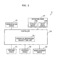
Fig. 2 shows a block diagram that indicates a configuration of theimage forming apparatus 1 inFig. 1 . As shown inFig. 2 , each one of theimage forming apparatuses 1 includes aprinting device 11, afacsimile device 12, animage scanning device 13, anoperation panel 14, acommunication device 15, and acontroller 16. - The
printing device 11 is an internal device that prints each image based on print image data on a paper sheet using electrophotography. - The
facsimile device 12 is an internal device that transmits and receives an image as a facsimile signal through a public telephone line using a modem. - The
image scanning device 13 is an internal device that scans a document image of a document and generates image data of the document image. - The
operation panel 14 is disposed on the case surface of theimage forming apparatus 1, and includes adisplay device 14a that displays information to a user and aninput device 14b that receives a user operation. For example, a liquid crystal display is used as thedisplay device 14a. A key switch, a touch panel or the like is used as theinput device 14b. - The
communication device 15 is a circuit that is connected to the network and performs data communication with another apparatus (e.g. the user terminal apparatus 3) connected to thenetwork 2. For example, a network interface is used as thecommunication device 15. - The
controller 16 includes a CPU (Central Processing Unit), a ROM (Read Only Memory), and a RAM (Random Access Memory), loads a program from the ROM or the like to the RAM, and executes the program with the CPU to embody various processing units. In this embodiment, an apparatusinformation transmitting unit 21 is embodied in thecontroller 16. - The apparatus
information transmitting unit 21 searches for a user terminal apparatus on thenetwork 2 using thecommunication device 15 with an identification code unique to theuser terminal apparatus 3 inputted to theinput device 14b and transmits apparatus information on thisimage forming apparatus 1 to theuser terminal apparatus 3 found by the search. -
Fig. 3 shows a block diagram that indicates a configuration of theuser terminal apparatus 3 inFig. 1 . Theuser terminal apparatus 3 is, for instance, a personal computer having network function in which programs such as an operating system and an application program have been installed. Each one of theuser terminal apparatuses 3 includes acommunication device 31, adisplay device 32, aninput device 33, astorage device 34, and aprocessor 35. - The
communication device 31 is a device that is connected to thenetwork 2 and performs data communication with other devices (e.g. the image forming apparatus 1) through thenetwork 2 in accordance with a predetermined communication protocol. For example, a network interface, a modem or the like is used as thecommunication device 31. Thedisplay device 32 is a device such as liquid crystal display that displays sorts of screens to a user of theterminal apparatus 3. Theinput device 33 is a device such as keyboard or mouse that detects a user operation. - The
storage device 34 is a device capable of storing data and programs. A non volatile storage medium with a large capacity is used as thestorage device 34, such as non volatile memory or hard disk drive. In thestorage device 34, an installeddriver program 41 and asetup program 42 are stored. Thus, thesetup program 42 is stored in a non-transitory computer readable recording medium. - The
processor 35 is a computer that includes a CPU, a ROM, and a RAM, and loads programs into the RAM from thestorage device 34, the ROM or the like and executes the program with the CPU to embody some processing units. - After the
user terminal apparatus 3 starts, sorts of programs are appropriately executed by theprocessor 35. In this embodiment, processing units such as an unshown operating system and acommunication processing unit 51 are embodied by theprocessor 35, and asetup processing unit 52 is embodied by executing thesetup program 42. - The
driver program 41 is executed for generating print data such as PDL data from a document data generated by an application and transmitting the print data to a predeterminedimage forming apparatus 1. - The
setup processing unit 52 includes an identificationcode managing unit 61, an apparatusinformation acquiring unit 62, and adriver setup unit 63. - The identification
code managing unit 61 generates an identification code unique to thisuser terminal apparatus 3 and displays the identification code on thedisplay device 32. When a broadcast search is performed with this identification code as a search key, the identificationcode managing unit 61 transmits a response that indicates this identification code was issued by thisuser terminal apparatus 3. - Using the
communication device 31, the apparatusinformation acquiring unit 62 receives apparatus information transmitted from theimage forming apparatus 1 to which the identification code was inputted. - The
driver setup unit 63 sets up thedriver program 41 on the basis of the apparatus information received by the apparatusinformation acquiring unit 62. Specifically, thedriver setup unit 63 changes values of setting data of the driver program 41 (e.g. a network identifier, a machine type and the like of the image forming apparatus to be controlled by the driver program 41) on the basis of the apparatus information received by the apparatusinformation acquiring unit 62. - The following part explains a setup process for the
driver program 41 in theuser terminal apparatus 3 in the aforementioned system.Fig. 4 shows a sequence diagram that explains a setup process for adriver program 41 in theuser terminal apparatus 3 in the system shown inFig. 1 . - Firstly, on the basis of a user operation to the
input device 33, theprocessor 35 executes thesetup program 42 and changes an operation mode of thesetup processing unit 52 to a connection waiting mode (in Step S1). - Upon changing to the connection waiting mode, the identification
code managing unit 61 generates an identification code unique to thisuser terminal apparatus 3 and displays the identification code on the display device 32 (in Step S2). Afterward, the apparatusinformation acquiring unit 62 waits until apparatus information is incoming. It should be noted that this identification code may be a serial number of theuser terminal apparatus 3, a MAC address of thecommunication device 31 or a code uniquely derived from such unique information. -
Fig. 5 shows a diagram that indicates an example of an identification code displayed on theuser terminal apparatus 3 inFig. 1 . As shown inFig. 5 , in a window, the identification code is displayed as a text together with a message that indicates the apparatus is in a connection waiting status. - A user who operates the
user terminal apparatus 3 memorizes or writes down the identification code displayed on thedisplay device 32 and goes to a place where a desiredimage forming apparatus 1 is located. Subsequently, the user operates theimage forming apparatus 1 to cause theimage forming apparatus 1 to display an input screen of the identification code on thedisplay device 14a. - On the basis of this user operation, the apparatus
information transmitting unit 21 displays an input screen of an identification code on thedisplay device 14a. -
Fig. 6 shows a diagram that indicates an example of an input screen of an identification code, displayed on theimage forming apparatus 1 inFig. 1 . - The user inputs the memorized or written down identification code into an input field in the input screen using the
input device 14b. The apparatusinformation transmitting unit 21 received the inputted identification code (in Step S3). - The apparatus
information transmitting unit 21 performs broadcast search on thenetwork 2 using thecommunication device 15 with the inputted identification code as a search key (in Step S4). The broadcast search is performed in accordance with a predetermined known communication protocol. - Upon receiving a message of the broadcast search, the
identification managing unit 61 of theuser terminal apparatus 3 in the connection waiting mode determines whether the identification code as the search key is equal to the identification code of thisuser terminal apparatus 3 or not. If the identification code as the search key is equal to the identification code of thisuser terminal apparatus 3, theidentification managing unit 61 transmits a response. - Upon receiving the response, the apparatus
information transmitting unit 21 of theimage forming apparatus 1 identifies a network identifier (e.g. IP address) of theuser terminal apparatus 3 that is the sender of the response, and transmits apparatus information (machine type, available communication protocol, and the like) of thisimage forming apparatus 1 to a destination specified by the network identifier (in Step S5). - The apparatus
information acquiring unit 62 of thisuser terminal apparatus 3 receives the apparatus information in the connection waiting mode, and thedriver setup unit 63 sets up thedriver program 41 on the basis of the apparatus information (in Step S6). - Therefore, this
user terminal apparatus 3 is enabled to use theimage forming apparatus 1 in which the user inputted the identification code. Specifically, an application or the like in thisuser terminal apparatus 3 is enabled to causes thisimage forming apparatus 1 to perform printing or the like using thedriver program 41. - After the user inputs the identification code to the
image forming apparatus 1, the aforementioned setup of thedriver program 41 is automatically performed in theuser terminal apparatus 3, and therefore, it is possible that the user goes to a place where anotherimage forming apparatus 1 is located without returning to a place where theuser terminal apparatus 3 is located and also inputs the identification code to this otherimage forming apparatus 1 as well, and causes the aforementioned setup of thedriver program 41 to be automatically performed in the user terminal apparatus 3 (in Steps S11 to S14). Thus, using one identification code, it is possible to automatically set up thedriver programs 41 for the plural image forming apparatus. - In the aforementioned embodiment, the
image forming apparatus 1 searches for auser terminal apparatus 3 on thenetwork 2 with the identification code unique to theuser terminal apparatus 3 inputted to theinput device 14b, and transmits apparatus information on thisimage forming apparatus 1 to theuser terminal apparatus 3 found by the search. Meanwhile, theuser terminal apparatus 3 displays the identification code unique to thisuser terminal apparatus 3 on thedisplay device 32, receives apparatus information transmitted from theimage forming apparatus 1 to which this identification code was inputted, and sets up thedriver program 41 on the basis of the received apparatus information. - Consequently, a user is required only to input an identification code displayed on the
user terminal apparatus 3 to a user-desiredimage forming apparatus 1, and therefore, even if the user does not have knowledge on network technology, the user can set up a driver of the user-desiredimage forming apparatus 1. - The description has been presented for purposes of illustration and description, and is not intended to be exhaustive or limited.
- It should be understood that various changes and modifications to the embodiments described herein will be apparent to those skilled in the art. Such changes and modifications may be made without departing from the spirit and scope of the present subject matter and without diminishing its intended advantages. It is therefore intended that such changes and modifications be covered by the appended claims.
Claims (5)
- An image forming system, comprising:an image forming apparatus (1) connected to a network (2); anda user terminal apparatus (3)connected to the network (2) and in which a driver program (41) of the image forming apparatus (1) is installed;wherein the image forming apparatus (1) comprises:an input device (14b) configured to receive an input of an identification code unique to the user terminal apparatus (3) on the basis of a user operation;an apparatus information transmitting unit (21) configured to search for a user terminal apparatus (3) on the network (2) using the identification code unique to the user terminal apparatus (3) inputted to the input device (14b) and transmit apparatus information on this image forming apparatus (1) to the user terminal apparatus (3) found by the search; andthe user terminal apparatus (3) comprises:a display device (32);an identification code managing unit (61) configured to display an identification code unique to this user terminal apparatus (3) on the display device (32);an apparatus information acquiring unit (62) configured to receive the apparatus information transmitted from the image forming apparatus (1) to which the identification code was inputted; anda driver setup unit (63) configured to set up the driver program (41) on the basis of the received apparatus information.
- The image forming system according to claim 1, further comprising plural image forming apparatuses (1) including the image forming apparatus (1);
wherein each one of the image forming apparatuses (1) comprises:said input device (14b), andsaid apparatus information transmitting unit (21); and
the apparatus information acquiring unit (21) is further configured to receive plural pieces of the apparatus information transmitted from the plural image forming apparatuses (1) to which the identification code was inputted, and
the driver setup unit (63) is further configured to set up respective driver programs (41) of the plural image forming apparatuses (1) on the basis of the received plural pieces of the apparatus information. - The image forming system according to claim 1, wherein:the identification code managing unit (61) is further configured to automatically display the identification code on the display device (32) upon changing to a connection waiting mode;the apparatus information acquiring unit (62) is further configured to wait in the connection waiting mode until the transmitted apparatus information is incoming; andthe driver setup unit (63) is further configured to set up the driver program (41) on the basis of the apparatus information received in the connection waiting mode.
- An image forming apparatus (1) to be connected to a network (2), comprising:an input device (14b) configured to receive an input of an identification code unique to a user terminal apparatus on the basis of a user operation;an apparatus information transmitting unit (21) configured to search for a user terminal apparatus (3) on the network (2) using the identification code inputted to the input device (14b) and transmit apparatus information on this image forming apparatus (1) to the user terminal apparatus (3) found by the search,wherein the identification code is unique to the user terminal apparatus (3) in which a driver program (41) of this image forming apparatus (1) has been installed.
- A non-transitory computer readable recording medium storing a setup program (42), wherein the setup program (42) causes a computer (35) in a user terminal apparatus (3) in which a driver program (41) is installed for an image forming apparatus (1) connected to a network (2) to act as:an identification code managing unit (61) configured to display an identification code unique to this user terminal apparatus (1) on a display device (32);an apparatus information acquiring unit (62) configured to receive the apparatus information transmitted from the image forming apparatus (1) to which the identification code was inputted; anda driver setup unit (63) configured to set up the driver program (41) on the basis of the received apparatus information.
Applications Claiming Priority (1)
| Application Number | Priority Date | Filing Date | Title |
|---|---|---|---|
| JP2013178663A JP5901589B2 (en) | 2013-08-29 | 2013-08-29 | Image forming system |
Publications (2)
| Publication Number | Publication Date |
|---|---|
| EP2843927A1 true EP2843927A1 (en) | 2015-03-04 |
| EP2843927B1 EP2843927B1 (en) | 2018-11-28 |
Family
ID=51453556
Family Applications (1)
| Application Number | Title | Priority Date | Filing Date |
|---|---|---|---|
| EP14002880.4A Not-in-force EP2843927B1 (en) | 2013-08-29 | 2014-08-19 | Image forming system, image forming apparatus, and non-transitory computer readable recording medium storing a setup program |
Country Status (4)
| Country | Link |
|---|---|
| US (1) | US9350891B2 (en) |
| EP (1) | EP2843927B1 (en) |
| JP (1) | JP5901589B2 (en) |
| CN (1) | CN104427171A (en) |
Citations (2)
| Publication number | Priority date | Publication date | Assignee | Title |
|---|---|---|---|---|
| US20060107039A1 (en) * | 2004-11-18 | 2006-05-18 | Konica Minolta Business Technologies, Inc. | Image formation system having authentication function |
| US20070067413A1 (en) * | 2005-08-31 | 2007-03-22 | Masahiro Nishio | Information processing apparatus, network device, control method therefor, computer program, and computer readable storage medium |
Family Cites Families (9)
| Publication number | Priority date | Publication date | Assignee | Title |
|---|---|---|---|---|
| JP2004280644A (en) * | 2003-03-18 | 2004-10-07 | Ricoh Co Ltd | Printing system, management device, and printing device search method |
| EP1696655A3 (en) * | 2005-02-25 | 2007-07-25 | Canon Kabushiki Kaisha | Information processor |
| JP4639917B2 (en) | 2005-04-07 | 2011-02-23 | コニカミノルタビジネステクノロジーズ株式会社 | Image forming apparatus and image forming system |
| JP4546356B2 (en) | 2005-08-31 | 2010-09-15 | キヤノン株式会社 | Image forming apparatus, control method therefor, program, and image forming system |
| JP4579799B2 (en) | 2005-09-02 | 2010-11-10 | キヤノン株式会社 | Image forming apparatus, control method therefor, program, and image forming system |
| JP5034993B2 (en) * | 2007-02-07 | 2012-09-26 | ブラザー工業株式会社 | Information processing apparatus and information processing method |
| JP5125304B2 (en) * | 2007-08-13 | 2013-01-23 | ブラザー工業株式会社 | Wireless communication connection system and network device |
| US8495706B2 (en) * | 2010-10-21 | 2013-07-23 | Kabushiki Kaisha Toshiba | Television apparatus, display control device, and display control method |
| CA2832447C (en) * | 2011-04-04 | 2021-05-18 | Blackberry Limited | Document management system using printer emulation |
-
2013
- 2013-08-29 JP JP2013178663A patent/JP5901589B2/en not_active Expired - Fee Related
-
2014
- 2014-08-19 EP EP14002880.4A patent/EP2843927B1/en not_active Not-in-force
- 2014-08-25 CN CN201410421958.8A patent/CN104427171A/en active Pending
- 2014-08-25 US US14/467,569 patent/US9350891B2/en active Active
Patent Citations (2)
| Publication number | Priority date | Publication date | Assignee | Title |
|---|---|---|---|---|
| US20060107039A1 (en) * | 2004-11-18 | 2006-05-18 | Konica Minolta Business Technologies, Inc. | Image formation system having authentication function |
| US20070067413A1 (en) * | 2005-08-31 | 2007-03-22 | Masahiro Nishio | Information processing apparatus, network device, control method therefor, computer program, and computer readable storage medium |
Also Published As
| Publication number | Publication date |
|---|---|
| CN104427171A (en) | 2015-03-18 |
| US9350891B2 (en) | 2016-05-24 |
| JP2015050487A (en) | 2015-03-16 |
| US20150062609A1 (en) | 2015-03-05 |
| EP2843927B1 (en) | 2018-11-28 |
| JP5901589B2 (en) | 2016-04-13 |
Similar Documents
| Publication | Publication Date | Title |
|---|---|---|
| US11949830B2 (en) | Printing apparatus capable of counting the number of times of printing, method for controlling printing apparatus, and storage medium | |
| JP6395374B2 (en) | Image forming apparatus, image forming apparatus control method, and computer-readable program | |
| US11372606B2 (en) | Server system | |
| US8947708B2 (en) | Information processing apparatus, method for controlling an information processing apparatus, and image forming system | |
| JP6238711B2 (en) | Printing apparatus, printing control method, and program | |
| US20130301069A1 (en) | Information processing device, computer program product, and image forming apparatus | |
| US20130046843A1 (en) | Information processing system, managing apparatus, and computer-readable storage medium | |
| US9329548B2 (en) | Terminal apparatus, image forming system, and non-transitory computer readable medium | |
| JP6331302B2 (en) | Information processing system, information acquisition apparatus, server, program, and information processing method | |
| US11645024B2 (en) | Resuming print job by using accounting information | |
| US10264161B2 (en) | Image processing apparatus, image processing method, and non-transitory computer readable medium | |
| JP2007323641A (en) | Electronic document output request processing control system and method | |
| CN107229437B (en) | Pull type printing system | |
| KR20170053580A (en) | Printing apparatus having wireless direct communication function and method of controlling the printing apparatus | |
| US11385842B2 (en) | Printing system, information processing apparatus, control method therefor, and storage medium | |
| US11340842B2 (en) | Server system | |
| EP2958346B1 (en) | Information processing apparatus, information processing method and recording medium | |
| US9864556B2 (en) | Image forming apparatus having web browser, method of controlling image forming apparatus, and storage medium | |
| US20140118766A1 (en) | Host device, driving method of the host device, image forming device, image forming method, and computer-readable recording medium | |
| US9262114B2 (en) | Information apparatus and information processing system | |
| JP6135480B2 (en) | Information processing program and information processing apparatus | |
| US20240314251A1 (en) | Image forming apparatus and method of controlling image forming apparatus | |
| CN105991867B (en) | Image forming apparatus and image forming method | |
| US20190342459A1 (en) | Image forming apparatus that carries out communication with multiple external apparatuses, control method for the image forming apparatus, and storage medium | |
| US9350891B2 (en) | Image forming system, image forming apparatus, and non-transitory computer readable recording medium storing a setup program |
Legal Events
| Date | Code | Title | Description |
|---|---|---|---|
| 17P | Request for examination filed |
Effective date: 20140819 |
|
| AK | Designated contracting states |
Kind code of ref document: A1 Designated state(s): AL AT BE BG CH CY CZ DE DK EE ES FI FR GB GR HR HU IE IS IT LI LT LU LV MC MK MT NL NO PL PT RO RS SE SI SK SM TR |
|
| AX | Request for extension of the european patent |
Extension state: BA ME |
|
| PUAI | Public reference made under article 153(3) epc to a published international application that has entered the european phase |
Free format text: ORIGINAL CODE: 0009012 |
|
| R17P | Request for examination filed (corrected) |
Effective date: 20150619 |
|
| RBV | Designated contracting states (corrected) |
Designated state(s): AL AT BE BG CH CY CZ DE DK EE ES FI FR GB GR HR HU IE IS IT LI LT LU LV MC MK MT NL NO PL PT RO RS SE SI SK SM TR |
|
| 17Q | First examination report despatched |
Effective date: 20151013 |
|
| STAA | Information on the status of an ep patent application or granted ep patent |
Free format text: STATUS: EXAMINATION IS IN PROGRESS |
|
| GRAP | Despatch of communication of intention to grant a patent |
Free format text: ORIGINAL CODE: EPIDOSNIGR1 |
|
| STAA | Information on the status of an ep patent application or granted ep patent |
Free format text: STATUS: GRANT OF PATENT IS INTENDED |
|
| INTG | Intention to grant announced |
Effective date: 20180703 |
|
| GRAS | Grant fee paid |
Free format text: ORIGINAL CODE: EPIDOSNIGR3 |
|
| GRAA | (expected) grant |
Free format text: ORIGINAL CODE: 0009210 |
|
| STAA | Information on the status of an ep patent application or granted ep patent |
Free format text: STATUS: THE PATENT HAS BEEN GRANTED |
|
| AK | Designated contracting states |
Kind code of ref document: B1 Designated state(s): AL AT BE BG CH CY CZ DE DK EE ES FI FR GB GR HR HU IE IS IT LI LT LU LV MC MK MT NL NO PL PT RO RS SE SI SK SM TR |
|
| REG | Reference to a national code |
Ref country code: CH Ref legal event code: EP |
|
| REG | Reference to a national code |
Ref country code: AT Ref legal event code: REF Ref document number: 1071639 Country of ref document: AT Kind code of ref document: T Effective date: 20181215 |
|
| REG | Reference to a national code |
Ref country code: DE Ref legal event code: R096 Ref document number: 602014036771 Country of ref document: DE |
|
| REG | Reference to a national code |
Ref country code: IE Ref legal event code: FG4D |
|
| REG | Reference to a national code |
Ref country code: NL Ref legal event code: MP Effective date: 20181128 |
|
| REG | Reference to a national code |
Ref country code: LT Ref legal event code: MG4D |
|
| REG | Reference to a national code |
Ref country code: AT Ref legal event code: MK05 Ref document number: 1071639 Country of ref document: AT Kind code of ref document: T Effective date: 20181128 |
|
| PG25 | Lapsed in a contracting state [announced via postgrant information from national office to epo] |
Ref country code: IS Free format text: LAPSE BECAUSE OF FAILURE TO SUBMIT A TRANSLATION OF THE DESCRIPTION OR TO PAY THE FEE WITHIN THE PRESCRIBED TIME-LIMIT Effective date: 20190328 Ref country code: FI Free format text: LAPSE BECAUSE OF FAILURE TO SUBMIT A TRANSLATION OF THE DESCRIPTION OR TO PAY THE FEE WITHIN THE PRESCRIBED TIME-LIMIT Effective date: 20181128 Ref country code: LV Free format text: LAPSE BECAUSE OF FAILURE TO SUBMIT A TRANSLATION OF THE DESCRIPTION OR TO PAY THE FEE WITHIN THE PRESCRIBED TIME-LIMIT Effective date: 20181128 Ref country code: AT Free format text: LAPSE BECAUSE OF FAILURE TO SUBMIT A TRANSLATION OF THE DESCRIPTION OR TO PAY THE FEE WITHIN THE PRESCRIBED TIME-LIMIT Effective date: 20181128 Ref country code: HR Free format text: LAPSE BECAUSE OF FAILURE TO SUBMIT A TRANSLATION OF THE DESCRIPTION OR TO PAY THE FEE WITHIN THE PRESCRIBED TIME-LIMIT Effective date: 20181128 Ref country code: NO Free format text: LAPSE BECAUSE OF FAILURE TO SUBMIT A TRANSLATION OF THE DESCRIPTION OR TO PAY THE FEE WITHIN THE PRESCRIBED TIME-LIMIT Effective date: 20190228 Ref country code: BG Free format text: LAPSE BECAUSE OF FAILURE TO SUBMIT A TRANSLATION OF THE DESCRIPTION OR TO PAY THE FEE WITHIN THE PRESCRIBED TIME-LIMIT Effective date: 20190228 Ref country code: LT Free format text: LAPSE BECAUSE OF FAILURE TO SUBMIT A TRANSLATION OF THE DESCRIPTION OR TO PAY THE FEE WITHIN THE PRESCRIBED TIME-LIMIT Effective date: 20181128 Ref country code: ES Free format text: LAPSE BECAUSE OF FAILURE TO SUBMIT A TRANSLATION OF THE DESCRIPTION OR TO PAY THE FEE WITHIN THE PRESCRIBED TIME-LIMIT Effective date: 20181128 |
|
| PG25 | Lapsed in a contracting state [announced via postgrant information from national office to epo] |
Ref country code: PT Free format text: LAPSE BECAUSE OF FAILURE TO SUBMIT A TRANSLATION OF THE DESCRIPTION OR TO PAY THE FEE WITHIN THE PRESCRIBED TIME-LIMIT Effective date: 20190328 Ref country code: GR Free format text: LAPSE BECAUSE OF FAILURE TO SUBMIT A TRANSLATION OF THE DESCRIPTION OR TO PAY THE FEE WITHIN THE PRESCRIBED TIME-LIMIT Effective date: 20190301 Ref country code: RS Free format text: LAPSE BECAUSE OF FAILURE TO SUBMIT A TRANSLATION OF THE DESCRIPTION OR TO PAY THE FEE WITHIN THE PRESCRIBED TIME-LIMIT Effective date: 20181128 Ref country code: AL Free format text: LAPSE BECAUSE OF FAILURE TO SUBMIT A TRANSLATION OF THE DESCRIPTION OR TO PAY THE FEE WITHIN THE PRESCRIBED TIME-LIMIT Effective date: 20181128 Ref country code: SE Free format text: LAPSE BECAUSE OF FAILURE TO SUBMIT A TRANSLATION OF THE DESCRIPTION OR TO PAY THE FEE WITHIN THE PRESCRIBED TIME-LIMIT Effective date: 20181128 |
|
| PG25 | Lapsed in a contracting state [announced via postgrant information from national office to epo] |
Ref country code: NL Free format text: LAPSE BECAUSE OF FAILURE TO SUBMIT A TRANSLATION OF THE DESCRIPTION OR TO PAY THE FEE WITHIN THE PRESCRIBED TIME-LIMIT Effective date: 20181128 |
|
| PG25 | Lapsed in a contracting state [announced via postgrant information from national office to epo] |
Ref country code: IT Free format text: LAPSE BECAUSE OF FAILURE TO SUBMIT A TRANSLATION OF THE DESCRIPTION OR TO PAY THE FEE WITHIN THE PRESCRIBED TIME-LIMIT Effective date: 20181128 Ref country code: PL Free format text: LAPSE BECAUSE OF FAILURE TO SUBMIT A TRANSLATION OF THE DESCRIPTION OR TO PAY THE FEE WITHIN THE PRESCRIBED TIME-LIMIT Effective date: 20181128 Ref country code: CZ Free format text: LAPSE BECAUSE OF FAILURE TO SUBMIT A TRANSLATION OF THE DESCRIPTION OR TO PAY THE FEE WITHIN THE PRESCRIBED TIME-LIMIT Effective date: 20181128 Ref country code: DK Free format text: LAPSE BECAUSE OF FAILURE TO SUBMIT A TRANSLATION OF THE DESCRIPTION OR TO PAY THE FEE WITHIN THE PRESCRIBED TIME-LIMIT Effective date: 20181128 |
|
| REG | Reference to a national code |
Ref country code: DE Ref legal event code: R097 Ref document number: 602014036771 Country of ref document: DE |
|
| PG25 | Lapsed in a contracting state [announced via postgrant information from national office to epo] |
Ref country code: EE Free format text: LAPSE BECAUSE OF FAILURE TO SUBMIT A TRANSLATION OF THE DESCRIPTION OR TO PAY THE FEE WITHIN THE PRESCRIBED TIME-LIMIT Effective date: 20181128 Ref country code: SM Free format text: LAPSE BECAUSE OF FAILURE TO SUBMIT A TRANSLATION OF THE DESCRIPTION OR TO PAY THE FEE WITHIN THE PRESCRIBED TIME-LIMIT Effective date: 20181128 Ref country code: RO Free format text: LAPSE BECAUSE OF FAILURE TO SUBMIT A TRANSLATION OF THE DESCRIPTION OR TO PAY THE FEE WITHIN THE PRESCRIBED TIME-LIMIT Effective date: 20181128 Ref country code: SK Free format text: LAPSE BECAUSE OF FAILURE TO SUBMIT A TRANSLATION OF THE DESCRIPTION OR TO PAY THE FEE WITHIN THE PRESCRIBED TIME-LIMIT Effective date: 20181128 |
|
| PLBE | No opposition filed within time limit |
Free format text: ORIGINAL CODE: 0009261 |
|
| STAA | Information on the status of an ep patent application or granted ep patent |
Free format text: STATUS: NO OPPOSITION FILED WITHIN TIME LIMIT |
|
| PG25 | Lapsed in a contracting state [announced via postgrant information from national office to epo] |
Ref country code: SI Free format text: LAPSE BECAUSE OF FAILURE TO SUBMIT A TRANSLATION OF THE DESCRIPTION OR TO PAY THE FEE WITHIN THE PRESCRIBED TIME-LIMIT Effective date: 20181128 |
|
| PGFP | Annual fee paid to national office [announced via postgrant information from national office to epo] |
Ref country code: DE Payment date: 20190806 Year of fee payment: 6 Ref country code: FR Payment date: 20190711 Year of fee payment: 6 |
|
| 26N | No opposition filed |
Effective date: 20190829 |
|
| PGFP | Annual fee paid to national office [announced via postgrant information from national office to epo] |
Ref country code: GB Payment date: 20190816 Year of fee payment: 6 |
|
| PG25 | Lapsed in a contracting state [announced via postgrant information from national office to epo] |
Ref country code: TR Free format text: LAPSE BECAUSE OF FAILURE TO SUBMIT A TRANSLATION OF THE DESCRIPTION OR TO PAY THE FEE WITHIN THE PRESCRIBED TIME-LIMIT Effective date: 20181128 |
|
| PG25 | Lapsed in a contracting state [announced via postgrant information from national office to epo] |
Ref country code: CH Free format text: LAPSE BECAUSE OF NON-PAYMENT OF DUE FEES Effective date: 20190831 Ref country code: LI Free format text: LAPSE BECAUSE OF NON-PAYMENT OF DUE FEES Effective date: 20190831 Ref country code: LU Free format text: LAPSE BECAUSE OF NON-PAYMENT OF DUE FEES Effective date: 20190819 Ref country code: MC Free format text: LAPSE BECAUSE OF FAILURE TO SUBMIT A TRANSLATION OF THE DESCRIPTION OR TO PAY THE FEE WITHIN THE PRESCRIBED TIME-LIMIT Effective date: 20181128 |
|
| REG | Reference to a national code |
Ref country code: BE Ref legal event code: MM Effective date: 20190831 |
|
| PG25 | Lapsed in a contracting state [announced via postgrant information from national office to epo] |
Ref country code: IE Free format text: LAPSE BECAUSE OF NON-PAYMENT OF DUE FEES Effective date: 20190819 |
|
| PG25 | Lapsed in a contracting state [announced via postgrant information from national office to epo] |
Ref country code: BE Free format text: LAPSE BECAUSE OF NON-PAYMENT OF DUE FEES Effective date: 20190831 |
|
| REG | Reference to a national code |
Ref country code: DE Ref legal event code: R119 Ref document number: 602014036771 Country of ref document: DE |
|
| GBPC | Gb: european patent ceased through non-payment of renewal fee |
Effective date: 20200819 |
|
| PG25 | Lapsed in a contracting state [announced via postgrant information from national office to epo] |
Ref country code: CY Free format text: LAPSE BECAUSE OF FAILURE TO SUBMIT A TRANSLATION OF THE DESCRIPTION OR TO PAY THE FEE WITHIN THE PRESCRIBED TIME-LIMIT Effective date: 20181128 |
|
| PG25 | Lapsed in a contracting state [announced via postgrant information from national office to epo] |
Ref country code: DE Free format text: LAPSE BECAUSE OF NON-PAYMENT OF DUE FEES Effective date: 20210302 Ref country code: HU Free format text: LAPSE BECAUSE OF FAILURE TO SUBMIT A TRANSLATION OF THE DESCRIPTION OR TO PAY THE FEE WITHIN THE PRESCRIBED TIME-LIMIT; INVALID AB INITIO Effective date: 20140819 Ref country code: MT Free format text: LAPSE BECAUSE OF FAILURE TO SUBMIT A TRANSLATION OF THE DESCRIPTION OR TO PAY THE FEE WITHIN THE PRESCRIBED TIME-LIMIT Effective date: 20181128 Ref country code: FR Free format text: LAPSE BECAUSE OF NON-PAYMENT OF DUE FEES Effective date: 20200831 |
|
| PG25 | Lapsed in a contracting state [announced via postgrant information from national office to epo] |
Ref country code: GB Free format text: LAPSE BECAUSE OF NON-PAYMENT OF DUE FEES Effective date: 20200819 |
|
| PG25 | Lapsed in a contracting state [announced via postgrant information from national office to epo] |
Ref country code: MK Free format text: LAPSE BECAUSE OF FAILURE TO SUBMIT A TRANSLATION OF THE DESCRIPTION OR TO PAY THE FEE WITHIN THE PRESCRIBED TIME-LIMIT Effective date: 20181128 |