EP2843857B1 - Method and system for testing isotropic sensitivity of a terminal - Google Patents
Method and system for testing isotropic sensitivity of a terminal Download PDFInfo
- Publication number
- EP2843857B1 EP2843857B1 EP13884948.4A EP13884948A EP2843857B1 EP 2843857 B1 EP2843857 B1 EP 2843857B1 EP 13884948 A EP13884948 A EP 13884948A EP 2843857 B1 EP2843857 B1 EP 2843857B1
- Authority
- EP
- European Patent Office
- Prior art keywords
- received signal
- signal strength
- terminal received
- theta
- terminal
- Prior art date
- Legal status (The legal status is an assumption and is not a legal conclusion. Google has not performed a legal analysis and makes no representation as to the accuracy of the status listed.)
- Active
Links
Images

Classifications
-
- H—ELECTRICITY
- H04—ELECTRIC COMMUNICATION TECHNIQUE
- H04B—TRANSMISSION
- H04B17/00—Monitoring; Testing
- H04B17/10—Monitoring; Testing of transmitters
- H04B17/101—Monitoring; Testing of transmitters for measurement of specific parameters of the transmitter or components thereof
- H04B17/102—Power radiated at antenna
-
- H—ELECTRICITY
- H04—ELECTRIC COMMUNICATION TECHNIQUE
- H04B—TRANSMISSION
- H04B17/00—Monitoring; Testing
- H04B17/20—Monitoring; Testing of receivers
- H04B17/29—Performance testing
-
- H—ELECTRICITY
- H04—ELECTRIC COMMUNICATION TECHNIQUE
- H04B—TRANSMISSION
- H04B17/00—Monitoring; Testing
- H04B17/30—Monitoring; Testing of propagation channels
- H04B17/309—Measuring or estimating channel quality parameters
- H04B17/318—Received signal strength
-
- H—ELECTRICITY
- H04—ELECTRIC COMMUNICATION TECHNIQUE
- H04B—TRANSMISSION
- H04B7/00—Radio transmission systems, i.e. using radiation field
- H04B7/02—Diversity systems; Multi-antenna system, i.e. transmission or reception using multiple antennas
- H04B7/10—Polarisation diversity; Directional diversity
-
- H—ELECTRICITY
- H04—ELECTRIC COMMUNICATION TECHNIQUE
- H04W—WIRELESS COMMUNICATION NETWORKS
- H04W88/00—Devices specially adapted for wireless communication networks, e.g. terminals, base stations or access point devices
- H04W88/02—Terminal devices
Definitions
- the present disclosure generally relates to the technical field of communications, and more particularly, to a method and a system for testing Total Isotropic Sensitivity (TIS) of a terminal.
- TIS Total Isotropic Sensitivity
- the testing system gradually decreases the transmitting power of the base station simulator, and then transmits data packets having a fixed length but random contents.
- the terminal transmits these data packets back to a base station simulator via a transmitting path.
- the base station simulator compares each bit of the data packets that are transmitted with the data packets that are received so as to calculate a bit error rate (BER) until the BER exceeds a standard threshold. Then, the transmitting power of the base station simulator when the BER exceeds the standard threshold is just the Effective Isotropic Sensitivity (EIS) of the current testing point.
- EIS Effective Isotropic Sensitivity
- the BER standard threshold is 2.44% for GSM (Global System of Mobile communication) and 0.1% for WCDMA (Wideband Code Division Multiple Access).
- the path loss (which is a fixed deviation value for a fixed frequency point and a fixed polarization direction of the measuring antenna in the darkroom) in the darkroom is compensated for the EISs. Then, an integration operation is made according to a formula to obtain the final Total Isotropic Sensitivity (TIS).
- TIS Total Isotropic Sensitivity
- the time consumed in this step determines the final testing time of the whole system.
- a TW patent application TW200934211 discloses a method for auto-testing the 3D stereo Total Isotropic Sensitivity (TIS) of a mobile phone.
- TIS is an average value of received sensitivities in all directions in the three-dimensional space.
- CTIA Cellular Telecommunications & Internet Association
- phi ⁇ -axis
- theta ⁇ -axis
- D1 only shows how to quickly obtain the final sensitivity value at one testing angle, however, each sensitivity value (that is, the 2D EIS test result) at each angle still must be measured, thus the TIS value can be calculated according to all of the sensitivity values at all of the testing angle. Therefore, the testing method of D1 also consumes a large time since each sensitivity value at each angle also still must be measured.
- D2 Test Plan for Mobile Station Over the Air Performance
- RSS receive signal strength
- EIS radiated effective isotropic sensitivity
- TIS final total isotropic sensitivity
- a technical problem to be solved in the present disclosure is to provide a method and a system for testing Total Isotropic Sensitivity (TIS) of a terminal, which take a short testing time and have a high testing efficiency.
- TIS Total Isotropic Sensitivity
- the present disclosure provides a method for testing TIS of a terminal, which comprises:
- the correspondence table is obtained by testing the base station power levels and the terminal received signal strengths, or is generated by means of an Equal Difference method in which as the base station signal strength decreases by per 1 dB, the terminal received signal strength also decreases by 1 dB.
- the step of rotating the rotating table to test a terminal received signal strength of the terminal at each Theta/Phi angle and in each antenna polarization direction and to generate a terminal received signal strength direction map comprises:
- the terminal received signal strength is tested at least twice or the terminal received signal strength at different base station power levels are tested, and then the results are averaged.
- the step of generating a terminal received signal strength direction map further comprises:
- the present disclosure further provides a system for testing TIS of a terminal, which comprises the terminal, a base station simulator, a darkroom and a controller, and the darkroom comprising a measuring antenna and a rotating table, wherein:
- the controller obtains the correspondence table by testing the base station power levels and the terminal received signal strengths, or adopts an Equal Difference method, in which as the base station signal strength decreases by per 1 dB, the terminal received signal strength also decreases by 1 dB, to generate the correspondence table.
- the rotating table is rotated to move the terminal sequentially to different Theta and Phi angles and to adjust the polarization direction of the antenna, and the controller tests the terminal received signal strength at each of the Theta/Phi angles and in each of the antenna polarization directions and forms the terminal received signal strength direction map according to all the terminal received signal strengths.
- the controller tests the terminal received signal strength at least twice or tests the terminal received signal strength at different base station power levels, and then averages the results.
- the controller searches for the best Phi angle and the best antenna polarization direction, re-tests the terminal received signal strength at the best Phi angle and in the best antenna polarization direction, and compares the terminal received signal strength obtained with the terminal received signal strength in the terminal received signal strength direction map to obtain a difference value;
- the controller corrects the terminal received signal strengths at the Theta angle corresponding to all the Phi angles and all the antenna polarization directions according to the difference value.
- the present disclosure provides the following benefits: by testing a terminal received signal strength at each Theta/Phi angle and in each antenna polarization direction and generating a terminal received signal strength direction map and a correspondence table between base station power levels and the terminal received signal strengths, the best Theta/Phi angle and the best antenna polarization direction are found and an EIS corresponding to the best Theta/Phi angle and the best antenna polarization direction is tested, and then EISs at other Theta/Phi angles and in other antenna polarization directions are calculated and integrated to obtain the terminal TIS.
- the testing time can be effectively reduced and the testing efficiency can be improved.
- FIG. 1 there is shown a schematic flowchart diagram of a first embodiment of a method for testing TIS of a terminal according to the present disclosure.
- the present disclosure provides a method for testing TIS of a terminal, which comprises:
- the TIS or terminal received signal strength direction map is basically the same for each of the channels, so it is sufficient to test the terminal received signal strength direction map of only one of the channels without having to test the terminal received signal strength direction map of each channel.
- the terminal received signal strength direction map is preferably, if there are three channels (i.e., a high channel, a medium channel, and a low channel) to be tested, then it is sufficient to test the terminal received signal strength direction map of only the medium channel.
- Step S13 generating a correspondence table between base station power levels and the terminal received signal strengths.
- the correspondence table may be obtained by testing the base station power levels and the terminal received signal strengths, or by means of an Equal Difference method in which as the base station signal strength decreases by per 1 dB, the terminal received signal strength also decreases by 1 dB.
- Step S14 searching for the best Theta/Phi angle and the best antenna polarization direction according to the terminal received signal strength direction map, and rotating the terminal to the best Theta/Phi angle and the best antenna polarization direction to test an EIS EIS best of all channels under test at the best Theta/Phi angle and in the best antenna polarization direction.
- the path loss in the darkroom needs to be compensated for the EIS EIS best , and is a fixed deviation value for a fixed frequency point and a fixed polarization direction of the measuring antenna.
- the base station simulator transmits data packets to the terminal via the measuring antenna, and the terminal transmits the data packets that are received back to the base station simulator via the communication antenna.
- the base station simulator calculates a bit error rate (BER) according to the data packets that are transmitted and the data packets that are received to adjust the transmitting power of the base station simulator.
- BER bit error rate
- the transmitting power of the base station simulator is just the EIS at the current Theta/Phi angle and in the current antenna polarization direction.
- the EIS EIS it is only necessary to test the EIS EIS best at the best Theat/Phi angle and in the best antenna polarization direction, and the EISs at other angles and in other polarization directions are calculated from the equation according to EIS.
- the testing time of each testing point is reduced from 3 ⁇ 16.4s to 4s, and the testing time of the whole testing is reduced from 118 minutes to about 10 minutes, so the testing efficiency is greatly improved.
- Step S16 integrating all the EISs to obtain the terminal TIS.
- the testing time can be effectively reduced and the testing efficiency can be improved.
- the system for testing TIS of a terminal according to the present disclosure comprises a terminal 20, a base station simulator 40, a darkroom 30 and a controller 50; and the darkroom 30 comprises a measuring antenna 302, a communication antenna 303 and a rotating table 301.
- the terminal 20 is placed on the rotating table 301 in the darkroom 30 to create a communication connection with the base station simulator 40 via the measuring antenna 302 and the communication antenna 303.
- the rotating table 301 is rotated to different Theta/Phi angles and antenna polarization directions so that the controller 50 tests a terminal received signal strength of the terminal 20 at each of the Theta/Phi angles and in each of the antenna polarization directions and generates a terminal received signal strength direction map.
- the terminal received signal strength is tested at least twice at each testing point, or the terminal received signal strengths are tested at different base station power levels and then the results are averaged as the terminal received signal strength of the testing point; and the number of times of the testing may be but is not limited to two.
- the power level of the base station simulator 40 is InitialCellPower in one test
- the power level of the base station simulator 40 is InitialCellPower-0.5 in the other test
- the two results obtained are averaged as the terminal received signal strength of the testing point, and this may increase the resolution of the terminal received signal strength from 1 dB to 0.5 dB.
- Each test only takes 4s.
- the terminal received signal strength direction map is formed according to all the terminal received signal strengths, and the terminal received signal strength direction map is saved so as to be called when needed, which can further reduce the testing time.
- the terminal received signal strength direction map may be saved as one file, but is not limited thereto.
- the controller 50 may make corrections on the terminal received signal strength direction map to increase the accuracy of the testing so that the result can become more stable. Specifically, at each of the Theta angles, the controller 50 searches for the best Phi angle and the best antenna polarization direction, re-tests the terminal received signal strength at the best Phi angle and in the best antenna polarization direction, and compares the terminal received signal strength obtained with the received signal strength in the original terminal received signal strength direction map to obtain a difference value; and the controller 50 corrects the terminal received signal strengths at the Theta angle corresponding to all the Phi angles and all the antenna polarization directions according to the difference value.
- the controller 50 generates the correspondence table between the base station power levels and the terminal received signal strengths by testing the base station power levels and the terminal received signal strengths, or by means of an Equal Difference method in which as the base station signal strength decreases by per 1 dB, the terminal received signal strength also decreases by 1 dB.
- the controller 50 searches for the best Theta/Phi angle and the best antenna polarization direction according to the terminal received signal strength direction map, and rotates the terminal 20 to the best Theta/Phi angle and the best antenna polarization direction to test an EIS EIS best of all channels under test at the best Theta/Phi angle and in the best antenna polarization direction.
- the path loss in the darkroom 30 needs to be compensated for the EIS EIS best , and is a fixed deviation value for a fixed frequency point and a fixed polarization direction of the measuring antenna 302.
- the base station simulator 40 transmits data packets to the terminal 20 via the measuring antenna 302, and the terminal 20 transmits the data packets that are received back to the base station simulator 40 via the communication antenna 30.
- the base station simulator 40 calculates a bit error rate (BER) according to the data packets that are transmitted and the data packets that are received to adjust the transmitting power of the base station simulator 40.
- BER bit error rate
- the transmitting power of the base station simulator 40 is just the EIS at the current Theta/Phi angle and in the current antenna polarization direction.
- controller 50 integrates all the EISs to obtain the terminal TIS.
- the controller 50 only needs to test the EIS EIS best at the best Theat/Phi angle and in the best antenna polarization direction, and the EISs at other angles and in other polarization directions are calculated from the equation according to the EIS.
- the same EIS searching operation needs to be performed on each testing point. Therefore, the testing time can be effectively reduced and the testing efficiency can be improved. Taking a conventional 3-channel WCDMA TIS test as an example, the testing time of each testing point is reduced from 3 ⁇ 16.4s to 4s, and the testing time of the whole testing is reduced from 118 minutes to about 10 minutes, so the testing efficiency is greatly improved.
- the testing time can be effectively reduced and the testing efficiency can be improved.
Landscapes
- Engineering & Computer Science (AREA)
- Computer Networks & Wireless Communication (AREA)
- Signal Processing (AREA)
- Physics & Mathematics (AREA)
- Electromagnetism (AREA)
- Quality & Reliability (AREA)
- Mobile Radio Communication Systems (AREA)
Description
- The present disclosure generally relates to the technical field of communications, and more particularly, to a method and a system for testing Total Isotropic Sensitivity (TIS) of a terminal.
- In a system for testing a terminal antenna, the Theta angle of a rotating table for testing needs to change from 0° to 180° at a step size of 30° (6 steps in total); and the Phi angle of the rotating table needs to change from 0° to 360° at a step size of 30° (12 steps in total). Furthermore, a horizontal polarization direction and a vertical polarization direction are used for a measuring antenna in the standard darkroom, so the total number of testing points are 6∗12∗2=144.
- At each testing point, the testing system gradually decreases the transmitting power of the base station simulator, and then transmits data packets having a fixed length but random contents. After receiving these data packets, the terminal transmits these data packets back to a base station simulator via a transmitting path. The base station simulator compares each bit of the data packets that are transmitted with the data packets that are received so as to calculate a bit error rate (BER) until the BER exceeds a standard threshold. Then, the transmitting power of the base station simulator when the BER exceeds the standard threshold is just the Effective Isotropic Sensitivity (EIS) of the current testing point. According to the 3GPP (The 3rd Generation Partnership Project) standard, for example, the BER standard threshold is 2.44% for GSM (Global System of Mobile communication) and 0.1% for WCDMA (Wideband Code Division Multiple Access).
- After the EIS of each of the testing points has been obtained, the path loss (which is a fixed deviation value for a fixed frequency point and a fixed polarization direction of the measuring antenna in the darkroom) in the darkroom is compensated for the EISs. Then, an integration operation is made according to a formula to obtain the final Total Isotropic Sensitivity (TIS).
- Because the same operations are executed for each of the testing points, the time consumed in this step determines the final testing time of the whole system. Taking a standard WCDMA TIS test as an example, one BER test has to use 41 data blocks and 82 WCDMA data frames, and takes 82∗10ms=0.82s. Averagely, 20 searches have to be made for one point, which takes 16.4s. Therefore, a conventional 3-channel WCDMA TIS needs to take a time of about 16.4∗144∗3=118 minutes. Accordingly, the EIS searching time in the system for testing a terminal antenna of the prior art is relatively long, which leads to a low testing efficiency.
- A TW patent application
TW200934211 (D1 - D1 only shows how to quickly obtain the final sensitivity value at one testing angle, however, each sensitivity value (that is, the 2D EIS test result) at each angle still must be measured, thus the TIS value can be calculated according to all of the sensitivity values at all of the testing angle. Therefore, the testing method of D1 also consumes a large time since each sensitivity value at each angle also still must be measured.
- Another prior art disclosed in CTIA Certification: Test Plan for Mobile Station Over the Air Performance (D2), shows an alternate TIS test procedure based on receive signal strength (RSS). However, in D2, each radiated effective isotropic sensitivity (EIS) at each direction and polarization also still must be measured, thus the final total isotropic sensitivity (TIS) are calculated by all of the measured EIS at all directions and polarizations. Thereby, the test of D2 also consumes a large time.
- A technical problem to be solved in the present disclosure is to provide a method and a system for testing Total Isotropic Sensitivity (TIS) of a terminal, which take a short testing time and have a high testing efficiency.
- To solve the aforesaid technical problem, the present disclosure provides a method for testing TIS of a terminal, which comprises:
- placing the terminal on a rotating table in a darkroom to create a communication connection with a base station simulator via a darkroom measuring antenna;
- rotating the rotating table to test a terminal received signal strength of the terminal at each Theta/Phi angle and in each antenna polarization direction and to generate a terminal received signal strength direction map;
- generating a correspondence table between base station power levels and the terminal received signal strengths;
- searching for the best Theta/Phi angle and the best antenna polarization direction according to the terminal received signal strength direction map, and rotating the terminal to the best Theta/Phi angle and the best antenna polarization direction to test an Effective Isotropic Sensitivity (EIS) EISbest of all channels under test at the best Theta/Phi angle and in the best antenna polarization direction;
- calculating EISs at other Theta/Phi angles and in other antenna polarization directions according to the EIS EISbest and the correspondence table: EIS=EISbest+(RXLEVELbest-RXLEVEL; where, RXLEVELbest is a terminal received signal strength at the best Theta/Phi angle and in the best antenna polarization direction, and RXLEVEL is the terminal received signal strength at the other Theta/Phi angles and in other antenna polarization directions; and
- integrating all the EISs to obtain the terminal TIS.
- The correspondence table is obtained by testing the base station power levels and the terminal received signal strengths, or is generated by means of an Equal Difference method in which as the base station signal strength decreases by per 1 dB, the terminal received signal strength also decreases by 1 dB.
- The step of rotating the rotating table to test a terminal received signal strength of the terminal at each Theta/Phi angle and in each antenna polarization direction and to generate a terminal received signal strength direction map comprises:
- rotating the rotating table to move the terminal sequentially to different Theta and Phi angles and adjusting the polarization direction of the antenna;
- testing the terminal received signal strength at each of the Theta/Phi angles and in each of the antenna polarization directions; and
- forming the terminal received signal strength direction map according to all the terminal received signal strengths.
- In the step of testing the terminal received signal strength at each of the Theta/Phi angles and in each of the antenna polarization directions, the terminal received signal strength is tested at least twice or the terminal received signal strength at different base station power levels are tested, and then the results are averaged.
- The step of generating a terminal received signal strength direction map further comprises:
- searching for the best Phi angle and the best antenna polarization direction at each of the Theta angles;
- re-testing the terminal received signal strength at the best Phi angle and in the best antenna polarization direction, and comparing the terminal received signal strength obtained with the received signal strength in the terminal received signal strength direction map to obtain a difference value; and
- correcting the terminal received signal strengths at the Theta angle corresponding to all the Phi angles and all the antenna polarization directions according to the difference value.
- The present disclosure further provides a system for testing TIS of a terminal, which comprises the terminal, a base station simulator, a darkroom and a controller, and the darkroom comprising a measuring antenna and a rotating table, wherein:
- the terminal is placed on the rotating table in the darkroom to create a communication connection with the base station simulator via the measuring antenna;
- the rotating table is rotated to different Theta/Phi angles and antenna polarization directions so that the controller tests a terminal received signal strength of the terminal at each of the Theta/Phi angles and in each of the antenna polarization directions and generates a terminal received signal strength direction map;
- the controller generates a correspondence table between base station power levels and the terminal received signal strengths;
- the controller searches for the best Theta/Phi angle and the best antenna polarization direction according to the terminal received signal strength direction map, and rotates the terminal to the best Theta/Phi angle and the best antenna polarization direction to test an EIS EISbest of all channels under test at the best Theta/Phi angle and in the best antenna polarization direction;
- the controller calculates EISs at other Theta/Phi angles and in other antenna polarization directions according to the EIS EISbest and the correspondence table: EIS=EISbest+(RXLEVELbest-RXLEVEL); where, RXLEVELbest is a terminal received signal strength at the best Theta/Phi angle and in the best antenna polarization direction, and RXLEVEL is the terminal received signal strength at the other Theta/Phi angles and in other antenna polarization directions; and the controller integrates all the EISs to obtain the terminal TIS.
- The controller obtains the correspondence table by testing the base station power levels and the terminal received signal strengths, or adopts an Equal Difference method, in which as the base station signal strength decreases by per 1 dB, the terminal received signal strength also decreases by 1 dB, to generate the correspondence table.
- The rotating table is rotated to move the terminal sequentially to different Theta and Phi angles and to adjust the polarization direction of the antenna, and the controller tests the terminal received signal strength at each of the Theta/Phi angles and in each of the antenna polarization directions and forms the terminal received signal strength direction map according to all the terminal received signal strengths.
- The controller tests the terminal received signal strength at least twice or tests the terminal received signal strength at different base station power levels, and then averages the results.
- At each of the Theta angles, the controller searches for the best Phi angle and the best antenna polarization direction, re-tests the terminal received signal strength at the best Phi angle and in the best antenna polarization direction, and compares the terminal received signal strength obtained with the terminal received signal strength in the terminal received signal strength direction map to obtain a difference value; and
- The controller corrects the terminal received signal strengths at the Theta angle corresponding to all the Phi angles and all the antenna polarization directions according to the difference value.
- Through the above solutions, the present disclosure provides the following benefits: by testing a terminal received signal strength at each Theta/Phi angle and in each antenna polarization direction and generating a terminal received signal strength direction map and a correspondence table between base station power levels and the terminal received signal strengths, the best Theta/Phi angle and the best antenna polarization direction are found and an EIS corresponding to the best Theta/Phi angle and the best antenna polarization direction is tested, and then EISs at other Theta/Phi angles and in other antenna polarization directions are calculated and integrated to obtain the terminal TIS. Thereby, the testing time can be effectively reduced and the testing efficiency can be improved.
-
-
FIG. 1 is a schematic flowchart diagram of a first embodiment of a method for testing TIS of a terminal according to the present disclosure; -
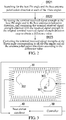
FIG. 2 is a schematic view illustrating a sub-process of step S12 shown inFIG. 1 according to the present disclosure; and -
FIG. 3 is a schematic structural view of a first embodiment of a system for testing TIS of a terminal according to the present disclosure. - Referring to
FIG. 1 , there is shown a schematic flowchart diagram of a first embodiment of a method for testing TIS of a terminal according to the present disclosure. As shown inFIG. 1 , the present disclosure provides a method for testing TIS of a terminal, which comprises: - Step S11: placing the terminal on a rotating table in a darkroom to create a communication connection with a base station simulator via a darkroom measuring antenna.
- Step S12: rotating the rotating table to test a terminal received signal strength of the terminal at each Theta/Phi angle and in each antenna polarization direction and to generate a terminal received signal strength direction map. At each of the Theta/Phi angles, two measurements need to be made by adjusting the polarization direction of the measuring antenna into the horizontal polarization and the vertical polarization respectively. One Theta/Phi angle and one antenna polarization direction form a testing point, and a base station simulator is maintained at a fixed signal strength, so the terminal received signal strength is tested only once at each testing point. The power level of the base station simulator is denoted by InitialCellPower. In other embodiments of the present disclosure, the terminal received signal strength is tested at least twice at each testing point or the terminal received signal strengths are tested at different base station power levels, and then the results are averaged as the terminal received signal strength of the testing point; and the number of times of the testing may be but is not limited to two. Preferably, the power level of the base station simulator is InitialCellPower in one test, the power level of the base station simulator is InitialCellPower-0.5 in the other test, and the two results obtained are averaged as the terminal received signal strength of the testing point, and this may increase the resolution of the terminal received signal strength from 1 dB to 0.5 dB. The InitialCellPower set forth herein may be but is not limited to a relatively high signal strength, and is preferably -40dBm. For example, if the base station power level in the first test is -15 dBm, then the strength obtained after the test is 40. In the second test, the base station power level is set to be -15.5 dBm, and if the strength obtained after the testing is still 40, then the final testing value is 40.5; and otherwise, is 40. In this way, the original testing error of 1dB may be corrected to 0.5 dB. If the number of times of the tests is increased at an interval of 0.25, then the testing error is also changed to 0.25 dB correspondingly. Each test only takes 4s. After the tests at all the testing points are completed, the terminal received signal strength direction map is formed according to all the terminal received signal strengths. In a preferred embodiment, the terminal received signal strength direction map is saved so as to be called when needed, which can further reduce the testing time. The terminal received signal strength direction map may be saved as one file, but is not limited thereto. If the terminal received signal strength direction map needs to be called when other terminals continue to be tested, the following method may be used to make corrections to increase the accuracy of the testing so that the result can become more stable. As shown in
FIG. 2 , there is shown a schematic view illustrating a sub-process of step S12 shown inFIG. 1 according to the present disclosure. The step S12 comprises:- Step S121: searching for the best Phi angle and the best antenna polarization direction at each of the Theta angles.
- Step S122: re-testing the terminal received signal strength at the best Phi angle and in the best antenna polarization direction, and comparing the terminal received signal strength obtained with the received signal strength in the original terminal received signal strength direction map to obtain a difference value.
- Step S123: correcting the terminal received signal strengths at the Theta angle corresponding to all the Phi angles and all the antenna polarization directions according to the difference value.
- For a communication frequency band, the TIS or terminal received signal strength direction map is basically the same for each of the channels, so it is sufficient to test the terminal received signal strength direction map of only one of the channels without having to test the terminal received signal strength direction map of each channel. Preferably, if there are three channels (i.e., a high channel, a medium channel, and a low channel) to be tested, then it is sufficient to test the terminal received signal strength direction map of only the medium channel.
- Step S13: generating a correspondence table between base station power levels and the terminal received signal strengths. The correspondence table may be obtained by testing the base station power levels and the terminal received signal strengths, or by means of an Equal Difference method in which as the base station signal strength decreases by per 1 dB, the terminal received signal strength also decreases by 1 dB.
- Step S14: searching for the best Theta/Phi angle and the best antenna polarization direction according to the terminal received signal strength direction map, and rotating the terminal to the best Theta/Phi angle and the best antenna polarization direction to test an EIS EISbest of all channels under test at the best Theta/Phi angle and in the best antenna polarization direction. The path loss in the darkroom needs to be compensated for the EIS EISbest, and is a fixed deviation value for a fixed frequency point and a fixed polarization direction of the measuring antenna. In this embodiment, the base station simulator transmits data packets to the terminal via the measuring antenna, and the terminal transmits the data packets that are received back to the base station simulator via the communication antenna. The base station simulator calculates a bit error rate (BER) according to the data packets that are transmitted and the data packets that are received to adjust the transmitting power of the base station simulator. When the BER reaches a standard threshold, the transmitting power of the base station simulator is just the EIS at the current Theta/Phi angle and in the current antenna polarization direction.
- Step S15: calculating EISs at other Theta/Phi angles and in other antenna polarization directions according to the EIS EISbest and the correspondence table:

- In this embodiment, it is only necessary to test the EIS EISbest at the best Theat/Phi angle and in the best antenna polarization direction, and the EISs at other angles and in other polarization directions are calculated from the equation according to EIS. However, in the conventional tests of the prior art, the same EIS searching operation needs to be performed on each testing point. Therefore, if the testing time of each testing point is reduced by 10s, then the total testing time is reduced by 144∗10s=24 minutes. For a conventional 3-channel testing, the testing time is reduced by 24∗3=72minutes. Taking a conventional 3-channel WCDMA TIS test as an example, the testing time of each testing point is reduced from 3∗16.4s to 4s, and the testing time of the whole testing is reduced from 118 minutes to about 10 minutes, so the testing efficiency is greatly improved.
- Step S16: integrating all the EISs to obtain the terminal TIS.
- In this embodiment, by testing the terminal received signal strength at each Theta/Phi angle and in each antenna polarization direction and generating the terminal received signal strength direction map and the correspondence table between the base station power levels and the terminal received signal strengths, searching for the best Theta/Phi angle and the best antenna polarization direction and testing the EIS corresponding to the best Theta/Phi angle and the best antenna polarization direction, and then calculating EISs at other Theta/Phi angles and in other antenna polarization directions and integrating the EISs at other Theta/Phi angles and in other antenna polarization directions to obtain the terminal TIS, the testing time can be effectively reduced and the testing efficiency can be improved.
- Referring to
FIG. 3 , there is shown a schematic structural view of a first embodiment of a system for testing TIS of a terminal according to the present disclosure. As shown inFIG. 3 , the system for testing TIS of a terminal according to the present disclosure comprises a terminal 20, abase station simulator 40, adarkroom 30 and acontroller 50; and thedarkroom 30 comprises a measuringantenna 302, acommunication antenna 303 and a rotating table 301. - The terminal 20 is placed on the rotating table 301 in the
darkroom 30 to create a communication connection with thebase station simulator 40 via the measuringantenna 302 and thecommunication antenna 303. - The rotating table 301 is rotated to different Theta/Phi angles and antenna polarization directions so that the
controller 50 tests a terminal received signal strength of the terminal 20 at each of the Theta/Phi angles and in each of the antenna polarization directions and generates a terminal received signal strength direction map. - In this embodiment, at each of the Theta/Phi angles, two measurements need to be made by adjusting the polarization direction of the measuring antenna into the horizontal polarization and the vertical polarization respectively. One Theta/Phi angle and one antenna polarization direction form a testing point. The
base station simulator 40 is maintained at a fixed signal strength, so the terminal received signal strength is tested only once at each testing point. The power level of thebase station simulator 40 is denoted by InitialCellPower. In other embodiments of the present disclosure, the terminal received signal strength is tested at least twice at each testing point, or the terminal received signal strengths are tested at different base station power levels and then the results are averaged as the terminal received signal strength of the testing point; and the number of times of the testing may be but is not limited to two. Preferably, the power level of thebase station simulator 40 is InitialCellPower in one test, the power level of thebase station simulator 40 is InitialCellPower-0.5 in the other test, and the two results obtained are averaged as the terminal received signal strength of the testing point, and this may increase the resolution of the terminal received signal strength from 1 dB to 0.5 dB. Each test only takes 4s. After the tests at all the testing points are completed, the terminal received signal strength direction map is formed according to all the terminal received signal strengths, and the terminal received signal strength direction map is saved so as to be called when needed, which can further reduce the testing time. The terminal received signal strength direction map may be saved as one file, but is not limited thereto. - If the terminal received signal strength direction map needs to be called when
other terminals 20 continue to be tested, thecontroller 50 may make corrections on the terminal received signal strength direction map to increase the accuracy of the testing so that the result can become more stable. Specifically, at each of the Theta angles, thecontroller 50 searches for the best Phi angle and the best antenna polarization direction, re-tests the terminal received signal strength at the best Phi angle and in the best antenna polarization direction, and compares the terminal received signal strength obtained with the received signal strength in the original terminal received signal strength direction map to obtain a difference value; and thecontroller 50 corrects the terminal received signal strengths at the Theta angle corresponding to all the Phi angles and all the antenna polarization directions according to the difference value. - The
controller 50 generates the correspondence table between the base station power levels and the terminal received signal strengths by testing the base station power levels and the terminal received signal strengths, or by means of an Equal Difference method in which as the base station signal strength decreases by per 1 dB, the terminal received signal strength also decreases by 1 dB. - The
controller 50 searches for the best Theta/Phi angle and the best antenna polarization direction according to the terminal received signal strength direction map, and rotates the terminal 20 to the best Theta/Phi angle and the best antenna polarization direction to test an EIS EISbest of all channels under test at the best Theta/Phi angle and in the best antenna polarization direction. The path loss in thedarkroom 30 needs to be compensated for the EIS EISbest, and is a fixed deviation value for a fixed frequency point and a fixed polarization direction of the measuringantenna 302. In this embodiment, thebase station simulator 40 transmits data packets to the terminal 20 via the measuringantenna 302, and the terminal 20 transmits the data packets that are received back to thebase station simulator 40 via thecommunication antenna 30. Thebase station simulator 40 calculates a bit error rate (BER) according to the data packets that are transmitted and the data packets that are received to adjust the transmitting power of thebase station simulator 40. When the BER reaches a standard threshold, the transmitting power of thebase station simulator 40 is just the EIS at the current Theta/Phi angle and in the current antenna polarization direction. - The
controller 50 calculates EISs at other Theta/Phi angles and in other antenna polarization directions according to the EIS EISbest and the correspondence table:
- Finally, the
controller 50 integrates all the EISs to obtain the terminal TIS. - In this embodiment, the
controller 50 only needs to test the EIS EISbest at the best Theat/Phi angle and in the best antenna polarization direction, and the EISs at other angles and in other polarization directions are calculated from the equation according to the EIS. However, in the conventional tests of the prior art, the same EIS searching operation needs to be performed on each testing point. Therefore, the testing time can be effectively reduced and the testing efficiency can be improved. Taking a conventional 3-channel WCDMA TIS test as an example, the testing time of each testing point is reduced from 3∗16.4s to 4s, and the testing time of the whole testing is reduced from 118 minutes to about 10 minutes, so the testing efficiency is greatly improved. - According to the above descriptions, by testing the terminal received signal strength at each Theta/Phi angle and in each antenna polarization direction and generating the terminal received signal strength direction map and the correspondence table between the base station power levels and the terminal received signal strengths, searching for the best Theta/Phi angle and the best antenna polarization direction and testing the EIS corresponding to the best Theta/Phi angle and the best antenna polarization direction, and then calculating EISs at other Theta/Phi angles and in other antenna polarization directions and integrating the EISs at other Theta/Phi angles and in other antenna polarization directions to obtain the terminal TIS, the testing time can be effectively reduced and the testing efficiency can be improved.
- What described above are only the embodiments of the present disclosure, but are not intended to limit the scope of the present disclosure. Any equivalent structures or equivalent process flow modifications that are made according to the specification and the attached drawings of the present disclosure, or any direct or indirect applications of the present disclosure in other related technical fields shall all be covered within the protection scope of the present disclosure.
Claims (14)
- A method for testing Total Isotropic Sensitivity (TIS) of a terminal (20), comprising:(S11): placing the terminal (20) on a rotating table (301) in a darkroom (30) to create a communication connection with a base station simulator (40) via a darkroom measuring antenna (302);(S12): rotating the rotating table (301) to test a terminal received signal strength of the terminal (20) at each Theta/Phi angle and in each antenna polarization direction, and to generate a terminal received signal strength direction map;(S13): generating a correspondence table between base station power levels and the terminal received signal strengths;
it is characterized in that, after the step (S13), the method further comprises:(S14): searching for the best Theta/Phi angle and the best antenna polarization direction according to the terminal received signal strength direction map, and rotating the terminal (20) to the best Theta/Phi angle and the best antenna polarization direction to test an Effective Isotropic Sensitivity (EIS) EISbest of all channels under test at the best Theta/Phi angle and in the best antenna polarization direction, wherein the best Theta/Phi angle and the best antenna polarization direction is a Theta/Phi angle and an antenna polarization direction of a testing point having a maximum terminal received signal strength in the terminal received signal strength direction map;(S15): calculating EISs at other Theta/Phi angles and in other antenna polarization directions according to the EIS EISbest and the correspondence table: (S16): integrating all the EISs to obtain the terminal TIS.
 - The method of claim 1, wherein the correspondence table is obtained by testing the base station power levels and the terminal received signal strengths.
- The method of claim 1, wherein the correspondence table is generated by means of an Equal Difference method in which as the base station signal strength decreases by per 1 dB, the terminal received signal strength also decreases by 1 dB.
- The method of claim 1, wherein the step of rotating the rotating table (301) to test a terminal received signal strength of the terminal at each Theta/Phi angle and in each antenna polarization direction and to generate a terminal received signal strength direction map comprises:rotating the rotating table (301) to move the terminal (20) sequentially to different Theta and Phi angles and adjusting the polarization direction of the antenna;testing the terminal received signal strength at each of the Theta/Phi angles and in each of the antenna polarization directions; andforming the terminal received signal strength direction map according to all the terminal received signal strengths.
- The method of claim 4, wherein in the step of testing the terminal received signal strength at each of the Theta/Phi angles and in each of the antenna polarization directions, the terminal received signal strength is tested at least twice, and then the results are averaged.
- The method of claim 4, wherein in the step of testing the terminal received signal strength at each of the Theta/Phi angles and in each of the antenna polarization directions, the terminal received signal strength at different base station power levels are tested, and then the results are averaged.
- The method of claim 1, wherein the step of generating a terminal received signal strength direction map further comprises:(S121): searching for the best Phi angle and the best antenna polarization direction at each of the Theta angles;(S122): re-testing the terminal received signal strength at the best Phi angle and in the best antenna polarization direction, and comparing the terminal received signal strength obtained with the terminal received signal strength in the terminal received signal strength direction map to obtain a difference value; and(S123): correcting the terminal received signal strengths at the Theta angle corresponding to all the Phi angles and all the antenna polarization directions according to the difference value.
- A system for testing TIS of a terminal (20), the system comprising the terminal (20), a base station simulator (40), a darkroom (30) and a controller (50), and the darkroom comprising a measuring antenna (302) and a rotating table (301), wherein:the terminal (20) is placed on the rotating table (301) in the darkroom (30) to create a communication connection with the base station simulator (40) via the measuring antenna (302);the rotating table (301) is rotated to different Theta/Phi angles and antenna polarization directions so that the controller (50) tests a terminal received signal strength of the terminal (20) at each of the Theta/Phi angles and in each of the antenna polarization directions and generates a terminal received signal strength direction map;the controller (50) generates a correspondence table between base station power levels and the terminal received signal strengths;it is characterized in that the controller (50) searches for the best Theta/Phi angle and the best antenna polarization direction according to the terminal received signal strength direction map, and rotates the terminal (20) to the best Theta/Phi angle and the best antenna polarization direction to test an EIS EISbest of all channels under test at the best Theta/Phi angle and in the best antenna polarization direction, wherein the best Theta/Phi angle and the best antenna polarization direction is a Theta/Phi angle and an antenna polarization direction of a testing point having a maximum terminal received signal strength in the terminal received signal strength direction map;the controller (50) calculates EISs at other Theta/Phi angles and in other antenna polarization directions according to the EIS EISbest and the correspondence table:
 where, RXLEVELbest is a terminal received signal strength at the best Theta/Phi angle and in the best antenna polarization direction, and RXLEVEL is the terminal received signal strength at the other Theta/Phi angles and in other antenna polarization directions; andthe controller (50) integrates all the EISs to obtain the terminal TIS.
 - The system of claim 8, wherein the controller (50) obtains the correspondence table by testing the base station power levels and the terminal received signal strengths.
- The system of claim 8, wherein the controller (50) adopts an Equal Difference method, in which as the base station signal strength decreases by per 1 dB, the terminal received signal strength also decreases by 1 dB, to generate the correspondence table.
- The system of claim 8, wherein the rotating table (301) is rotated to move the terminal (20) sequentially to different Theta and Phi angles and to adjust the polarization direction of the antenna, and the controller (50) tests the terminal received signal strength at each of the Theta/Phi angles and in each of the antenna polarization directions and forms the terminal received signal strength direction map according to all the terminal received signal strengths.
- The system of claim 11, wherein the controller (50) tests the terminal received signal strength at least twice, and then averages the results.
- The system of claim 11, wherein the controller (50) tests the terminal received signal strength at different base station power levels, and then averages the results.
- The system of claim 8, wherein, at each of the Theta angles, the controller (50) searches for the best Phi angle and the best antenna polarization direction, re-tests the terminal received signal strength at the best Phi angle and in the best antenna polarization direction, and compares the terminal received signal strength obtained with the terminal received signal strength in the terminal received signal strength direction map to obtain a difference value; and
the controller (50) corrects the terminal received signal strengths at the Theta angle corresponding to all the Phi angles and all the antenna polarization directions according to the difference value.
Applications Claiming Priority (2)
| Application Number | Priority Date | Filing Date | Title |
|---|---|---|---|
| CN201310205601.1A CN103297161B (en) | 2013-05-28 | 2013-05-28 | A kind of terminal antenna receiving sensitivity method of testing and system |
| PCT/CN2013/081893 WO2014190626A1 (en) | 2013-05-28 | 2013-08-20 | Method and system for testing isotropic sensitivity of a terminal |
Publications (3)
| Publication Number | Publication Date |
|---|---|
| EP2843857A1 EP2843857A1 (en) | 2015-03-04 |
| EP2843857A4 EP2843857A4 (en) | 2015-11-18 |
| EP2843857B1 true EP2843857B1 (en) | 2019-05-15 |
Family
ID=49097541
Family Applications (1)
| Application Number | Title | Priority Date | Filing Date |
|---|---|---|---|
| EP13884948.4A Active EP2843857B1 (en) | 2013-05-28 | 2013-08-20 | Method and system for testing isotropic sensitivity of a terminal |
Country Status (5)
| Country | Link |
|---|---|
| US (1) | US9236959B2 (en) |
| EP (1) | EP2843857B1 (en) |
| CN (1) | CN103297161B (en) |
| ES (1) | ES2728198T3 (en) |
| WO (1) | WO2014190626A1 (en) |
Families Citing this family (12)
| Publication number | Priority date | Publication date | Assignee | Title |
|---|---|---|---|---|
| CN104215855A (en) * | 2014-09-09 | 2014-12-17 | 深圳市佳沃通信技术有限公司 | Measuring distance adjustable OTA (over-the-air) test darkroom |
| CN104931811B (en) * | 2015-05-05 | 2019-06-04 | 惠州Tcl移动通信有限公司 | A kind of mobile terminal antenna testing method and device |
| CN105738710B (en) * | 2016-03-29 | 2018-09-11 | 北京森馥科技股份有限公司 | A kind of radio-frequency electromagnetic method of environmental monitoring |
| CN108120880A (en) * | 2017-12-22 | 2018-06-05 | 广州广电计量检测无锡有限公司 | Transmitting radar antenna conducted emission and susceptibility test platform and its test method |
| CN108111232B (en) * | 2018-03-01 | 2023-06-20 | 上海鸿洛通信电子有限公司 | Test darkroom and test system |
| CN108847903A (en) * | 2018-06-19 | 2018-11-20 | Oppo广东移动通信有限公司 | Electronic equipment receiving sensitivity test system, method and device |
| CN109586748B (en) | 2018-10-24 | 2020-11-13 | 惠州Tcl移动通信有限公司 | Method and terminal for reducing poor coupling sensitivity, and device with storage function |
| US11451979B2 (en) * | 2019-08-14 | 2022-09-20 | At&T Intellectual Property I, L.P. | Device testing optimization for 5G or other next generation network |
| CN112394233B (en) | 2019-08-16 | 2024-07-30 | 稜研科技股份有限公司 | Antenna packaging verification board |
| CN110995373A (en) * | 2019-12-19 | 2020-04-10 | 紫光展讯通信(惠州)有限公司 | Conduction sensitivity measuring method and device, storage medium and comprehensive measuring terminal |
| CN111988094B (en) * | 2020-09-18 | 2023-03-31 | 深圳市通用测试系统有限公司 | Wireless performance testing device, system, method, equipment and storage medium |
| CN112666406B (en) * | 2020-12-24 | 2023-11-03 | 福州物联网开放实验室有限公司 | A quick test method for the receiving sensitivity of antennas transmitting and receiving communications with the same frequency |
Family Cites Families (7)
| Publication number | Priority date | Publication date | Assignee | Title |
|---|---|---|---|---|
| US7773964B2 (en) * | 2004-10-25 | 2010-08-10 | Qualcomm Incorporated | Systems, methods and apparatus for determining a radiated performance of a wireless device |
| DE602008000050D1 (en) | 2007-06-15 | 2009-08-27 | Research In Motion Ltd | System for determining total isotropic sensitivity using a received signal strength indicator value and associated methods |
| TW200934211A (en) * | 2008-01-18 | 2009-08-01 | Arima Communication Corp | Automatic test method for speeding up total isotropic sensitivity of mobile phone |
| US8761684B2 (en) * | 2009-02-13 | 2014-06-24 | Spirent Communications, Inc. | Method and apparatus for virtual desktop OTA |
| CN101510806B (en) * | 2009-03-06 | 2012-08-29 | 深圳市鼎立方无线技术有限公司 | Method and apparatus for testing total omnidirectional sensitivity of transmit-receive cofrequency mobile terminal |
| CN102237933B (en) * | 2010-04-26 | 2014-02-26 | 深圳市鼎立方无线技术有限公司 | Method and device for testing effective isotropic sensitivity (EIS) |
| CN102185950B (en) | 2011-06-03 | 2013-12-18 | 惠州Tcl移动通信有限公司 | Radio-frequency testing device and radio-frequency testing method for multi-antenna handset |
-
2013
- 2013-05-28 CN CN201310205601.1A patent/CN103297161B/en active Active
- 2013-08-20 ES ES13884948T patent/ES2728198T3/en active Active
- 2013-08-20 WO PCT/CN2013/081893 patent/WO2014190626A1/en not_active Ceased
- 2013-08-20 EP EP13884948.4A patent/EP2843857B1/en active Active
- 2013-08-20 US US14/433,219 patent/US9236959B2/en active Active
Non-Patent Citations (1)
| Title |
|---|
| None * |
Also Published As
| Publication number | Publication date |
|---|---|
| ES2728198T3 (en) | 2019-10-22 |
| CN103297161A (en) | 2013-09-11 |
| CN103297161B (en) | 2016-03-02 |
| EP2843857A4 (en) | 2015-11-18 |
| US20150263815A1 (en) | 2015-09-17 |
| EP2843857A1 (en) | 2015-03-04 |
| WO2014190626A1 (en) | 2014-12-04 |
| US9236959B2 (en) | 2016-01-12 |
Similar Documents
| Publication | Publication Date | Title |
|---|---|---|
| EP2843857B1 (en) | Method and system for testing isotropic sensitivity of a terminal | |
| US11005580B2 (en) | Array antenna calibration method and device | |
| US11988754B2 (en) | Clock offset determination method and apparatus | |
| EP3293898B1 (en) | Method and device for testing antenna of mobile terminal | |
| US12155461B2 (en) | Clock offset determination method, clock offset processing method, device, and system | |
| US12532282B2 (en) | Method and apparatus for correcting transmitting channel delay, and storage medium | |
| CN102237933B (en) | Method and device for testing effective isotropic sensitivity (EIS) | |
| EP2993481A1 (en) | Fast test method for total radiation power of terminal antenna | |
| US9306680B2 (en) | Method and device for calibrating frequency synthesizer in communication terminal | |
| US11108450B2 (en) | Beam measurement method and apparatus | |
| CN106162722B (en) | A kind of mutually interference method for rapidly testing and system | |
| CN104683039B (en) | The crystal oscillator frequency calibration method and calibrating installation of communication terminal | |
| WO2019062724A1 (en) | Method for determining current state of beam reciprocity capability, and terminal | |
| EP4324266A1 (en) | Methods and apparatuses of measuring downlink positioning reference signal | |
| CN103298020A (en) | WIFI OTA (wireless fidelity over the air) testing method and system of mobile terminal | |
| EP2493238B1 (en) | Method and device for path loss acquisition | |
| CN106160895B (en) | A kind of mutual disturbed test method and system suitable for reverberation chamber | |
| CN113748720A (en) | Information reporting method and device and user equipment | |
| CN103916899A (en) | Interference signal generating device and method, and test signal generating system and method | |
| US20240244579A1 (en) | Methods and apparatus of priority of processing downlink positioning reference signal | |
| CN111327370B (en) | Radio frequency index determination method and device | |
| CN103152806A (en) | Power control method and device in communication between machines | |
| CN104661294B (en) | The calibration method and calibrating installation of transmitter in communication system | |
| CN103546329B (en) | A kind of engineering parameter calibration steps and the network equipment | |
| WO2023180970A1 (en) | Methods and apparatus of frequency domain phase measurement and positioning reporting |
Legal Events
| Date | Code | Title | Description |
|---|---|---|---|
| PUAI | Public reference made under article 153(3) epc to a published international application that has entered the european phase |
Free format text: ORIGINAL CODE: 0009012 |
|
| 17P | Request for examination filed |
Effective date: 20141125 |
|
| AK | Designated contracting states |
Kind code of ref document: A1 Designated state(s): AL AT BE BG CH CY CZ DE DK EE ES FI FR GB GR HR HU IE IS IT LI LT LU LV MC MK MT NL NO PL PT RO RS SE SI SK SM TR |
|
| AX | Request for extension of the european patent |
Extension state: BA ME |
|
| RA4 | Supplementary search report drawn up and despatched (corrected) |
Effective date: 20151020 |
|
| RIC1 | Information provided on ipc code assigned before grant |
Ipc: G01R 29/10 20060101ALI20151013BHEP Ipc: H04B 17/29 20150101ALI20151013BHEP Ipc: H04B 17/10 20150101AFI20151013BHEP |
|
| DAX | Request for extension of the european patent (deleted) | ||
| STAA | Information on the status of an ep patent application or granted ep patent |
Free format text: STATUS: EXAMINATION IS IN PROGRESS |
|
| 17Q | First examination report despatched |
Effective date: 20170928 |
|
| REG | Reference to a national code |
Ref country code: DE Ref legal event code: R079 Ref document number: 602013055610 Country of ref document: DE Free format text: PREVIOUS MAIN CLASS: H04B0017000000 Ipc: H04B0017100000 |
|
| GRAJ | Information related to disapproval of communication of intention to grant by the applicant or resumption of examination proceedings by the epo deleted |
Free format text: ORIGINAL CODE: EPIDOSDIGR1 |
|
| STAA | Information on the status of an ep patent application or granted ep patent |
Free format text: STATUS: GRANT OF PATENT IS INTENDED |
|
| GRAP | Despatch of communication of intention to grant a patent |
Free format text: ORIGINAL CODE: EPIDOSNIGR1 |
|
| RIC1 | Information provided on ipc code assigned before grant |
Ipc: H04W 84/00 20090101ALI20190131BHEP Ipc: H04W 88/02 20090101ALN20190131BHEP Ipc: H04B 17/318 20150101ALI20190131BHEP Ipc: H04B 17/29 20150101ALI20190131BHEP Ipc: H04B 7/10 20170101ALI20190131BHEP Ipc: H04B 17/10 20150101AFI20190131BHEP |
|
| INTG | Intention to grant announced |
Effective date: 20190213 |
|
| GRAS | Grant fee paid |
Free format text: ORIGINAL CODE: EPIDOSNIGR3 |
|
| GRAA | (expected) grant |
Free format text: ORIGINAL CODE: 0009210 |
|
| STAA | Information on the status of an ep patent application or granted ep patent |
Free format text: STATUS: THE PATENT HAS BEEN GRANTED |
|
| AK | Designated contracting states |
Kind code of ref document: B1 Designated state(s): AL AT BE BG CH CY CZ DE DK EE ES FI FR GB GR HR HU IE IS IT LI LT LU LV MC MK MT NL NO PL PT RO RS SE SI SK SM TR |
|
| REG | Reference to a national code |
Ref country code: CH Ref legal event code: EP |
|
| REG | Reference to a national code |
Ref country code: DE Ref legal event code: R096 Ref document number: 602013055610 Country of ref document: DE |
|
| REG | Reference to a national code |
Ref country code: IE Ref legal event code: FG4D |
|
| REG | Reference to a national code |
Ref country code: NL Ref legal event code: MP Effective date: 20190515 |
|
| REG | Reference to a national code |
Ref country code: LT Ref legal event code: MG4D |
|
| REG | Reference to a national code |
Ref country code: ES Ref legal event code: FG2A Ref document number: 2728198 Country of ref document: ES Kind code of ref document: T3 Effective date: 20191022 |
|
| PG25 | Lapsed in a contracting state [announced via postgrant information from national office to epo] |
Ref country code: NL Free format text: LAPSE BECAUSE OF FAILURE TO SUBMIT A TRANSLATION OF THE DESCRIPTION OR TO PAY THE FEE WITHIN THE PRESCRIBED TIME-LIMIT Effective date: 20190515 Ref country code: LT Free format text: LAPSE BECAUSE OF FAILURE TO SUBMIT A TRANSLATION OF THE DESCRIPTION OR TO PAY THE FEE WITHIN THE PRESCRIBED TIME-LIMIT Effective date: 20190515 Ref country code: HR Free format text: LAPSE BECAUSE OF FAILURE TO SUBMIT A TRANSLATION OF THE DESCRIPTION OR TO PAY THE FEE WITHIN THE PRESCRIBED TIME-LIMIT Effective date: 20190515 Ref country code: FI Free format text: LAPSE BECAUSE OF FAILURE TO SUBMIT A TRANSLATION OF THE DESCRIPTION OR TO PAY THE FEE WITHIN THE PRESCRIBED TIME-LIMIT Effective date: 20190515 Ref country code: SE Free format text: LAPSE BECAUSE OF FAILURE TO SUBMIT A TRANSLATION OF THE DESCRIPTION OR TO PAY THE FEE WITHIN THE PRESCRIBED TIME-LIMIT Effective date: 20190515 Ref country code: AL Free format text: LAPSE BECAUSE OF FAILURE TO SUBMIT A TRANSLATION OF THE DESCRIPTION OR TO PAY THE FEE WITHIN THE PRESCRIBED TIME-LIMIT Effective date: 20190515 Ref country code: NO Free format text: LAPSE BECAUSE OF FAILURE TO SUBMIT A TRANSLATION OF THE DESCRIPTION OR TO PAY THE FEE WITHIN THE PRESCRIBED TIME-LIMIT Effective date: 20190815 Ref country code: PT Free format text: LAPSE BECAUSE OF FAILURE TO SUBMIT A TRANSLATION OF THE DESCRIPTION OR TO PAY THE FEE WITHIN THE PRESCRIBED TIME-LIMIT Effective date: 20190915 |
|
| PG25 | Lapsed in a contracting state [announced via postgrant information from national office to epo] |
Ref country code: LV Free format text: LAPSE BECAUSE OF FAILURE TO SUBMIT A TRANSLATION OF THE DESCRIPTION OR TO PAY THE FEE WITHIN THE PRESCRIBED TIME-LIMIT Effective date: 20190515 Ref country code: GR Free format text: LAPSE BECAUSE OF FAILURE TO SUBMIT A TRANSLATION OF THE DESCRIPTION OR TO PAY THE FEE WITHIN THE PRESCRIBED TIME-LIMIT Effective date: 20190816 Ref country code: RS Free format text: LAPSE BECAUSE OF FAILURE TO SUBMIT A TRANSLATION OF THE DESCRIPTION OR TO PAY THE FEE WITHIN THE PRESCRIBED TIME-LIMIT Effective date: 20190515 Ref country code: BG Free format text: LAPSE BECAUSE OF FAILURE TO SUBMIT A TRANSLATION OF THE DESCRIPTION OR TO PAY THE FEE WITHIN THE PRESCRIBED TIME-LIMIT Effective date: 20190815 |
|
| REG | Reference to a national code |
Ref country code: AT Ref legal event code: MK05 Ref document number: 1134657 Country of ref document: AT Kind code of ref document: T Effective date: 20190515 |
|
| PG25 | Lapsed in a contracting state [announced via postgrant information from national office to epo] |
Ref country code: RO Free format text: LAPSE BECAUSE OF FAILURE TO SUBMIT A TRANSLATION OF THE DESCRIPTION OR TO PAY THE FEE WITHIN THE PRESCRIBED TIME-LIMIT Effective date: 20190515 Ref country code: CZ Free format text: LAPSE BECAUSE OF FAILURE TO SUBMIT A TRANSLATION OF THE DESCRIPTION OR TO PAY THE FEE WITHIN THE PRESCRIBED TIME-LIMIT Effective date: 20190515 Ref country code: EE Free format text: LAPSE BECAUSE OF FAILURE TO SUBMIT A TRANSLATION OF THE DESCRIPTION OR TO PAY THE FEE WITHIN THE PRESCRIBED TIME-LIMIT Effective date: 20190515 Ref country code: AT Free format text: LAPSE BECAUSE OF FAILURE TO SUBMIT A TRANSLATION OF THE DESCRIPTION OR TO PAY THE FEE WITHIN THE PRESCRIBED TIME-LIMIT Effective date: 20190515 Ref country code: DK Free format text: LAPSE BECAUSE OF FAILURE TO SUBMIT A TRANSLATION OF THE DESCRIPTION OR TO PAY THE FEE WITHIN THE PRESCRIBED TIME-LIMIT Effective date: 20190515 Ref country code: SK Free format text: LAPSE BECAUSE OF FAILURE TO SUBMIT A TRANSLATION OF THE DESCRIPTION OR TO PAY THE FEE WITHIN THE PRESCRIBED TIME-LIMIT Effective date: 20190515 |
|
| REG | Reference to a national code |
Ref country code: DE Ref legal event code: R097 Ref document number: 602013055610 Country of ref document: DE |
|
| PG25 | Lapsed in a contracting state [announced via postgrant information from national office to epo] |
Ref country code: SM Free format text: LAPSE BECAUSE OF FAILURE TO SUBMIT A TRANSLATION OF THE DESCRIPTION OR TO PAY THE FEE WITHIN THE PRESCRIBED TIME-LIMIT Effective date: 20190515 |
|
| PLBE | No opposition filed within time limit |
Free format text: ORIGINAL CODE: 0009261 |
|
| STAA | Information on the status of an ep patent application or granted ep patent |
Free format text: STATUS: NO OPPOSITION FILED WITHIN TIME LIMIT |
|
| PG25 | Lapsed in a contracting state [announced via postgrant information from national office to epo] |
Ref country code: TR Free format text: LAPSE BECAUSE OF FAILURE TO SUBMIT A TRANSLATION OF THE DESCRIPTION OR TO PAY THE FEE WITHIN THE PRESCRIBED TIME-LIMIT Effective date: 20190515 |
|
| 26N | No opposition filed |
Effective date: 20200218 |
|
| PG25 | Lapsed in a contracting state [announced via postgrant information from national office to epo] |
Ref country code: PL Free format text: LAPSE BECAUSE OF FAILURE TO SUBMIT A TRANSLATION OF THE DESCRIPTION OR TO PAY THE FEE WITHIN THE PRESCRIBED TIME-LIMIT Effective date: 20190515 |
|
| PG25 | Lapsed in a contracting state [announced via postgrant information from national office to epo] |
Ref country code: LU Free format text: LAPSE BECAUSE OF NON-PAYMENT OF DUE FEES Effective date: 20190820 Ref country code: SI Free format text: LAPSE BECAUSE OF FAILURE TO SUBMIT A TRANSLATION OF THE DESCRIPTION OR TO PAY THE FEE WITHIN THE PRESCRIBED TIME-LIMIT Effective date: 20190515 Ref country code: MC Free format text: LAPSE BECAUSE OF FAILURE TO SUBMIT A TRANSLATION OF THE DESCRIPTION OR TO PAY THE FEE WITHIN THE PRESCRIBED TIME-LIMIT Effective date: 20190515 Ref country code: CH Free format text: LAPSE BECAUSE OF NON-PAYMENT OF DUE FEES Effective date: 20190831 Ref country code: LI Free format text: LAPSE BECAUSE OF NON-PAYMENT OF DUE FEES Effective date: 20190831 |
|
| REG | Reference to a national code |
Ref country code: BE Ref legal event code: MM Effective date: 20190831 |
|
| PG25 | Lapsed in a contracting state [announced via postgrant information from national office to epo] |
Ref country code: IE Free format text: LAPSE BECAUSE OF NON-PAYMENT OF DUE FEES Effective date: 20190820 |
|
| PG25 | Lapsed in a contracting state [announced via postgrant information from national office to epo] |
Ref country code: BE Free format text: LAPSE BECAUSE OF NON-PAYMENT OF DUE FEES Effective date: 20190831 |
|
| PG25 | Lapsed in a contracting state [announced via postgrant information from national office to epo] |
Ref country code: CY Free format text: LAPSE BECAUSE OF FAILURE TO SUBMIT A TRANSLATION OF THE DESCRIPTION OR TO PAY THE FEE WITHIN THE PRESCRIBED TIME-LIMIT Effective date: 20190515 |
|
| PG25 | Lapsed in a contracting state [announced via postgrant information from national office to epo] |
Ref country code: IS Free format text: LAPSE BECAUSE OF FAILURE TO SUBMIT A TRANSLATION OF THE DESCRIPTION OR TO PAY THE FEE WITHIN THE PRESCRIBED TIME-LIMIT Effective date: 20190915 |
|
| PG25 | Lapsed in a contracting state [announced via postgrant information from national office to epo] |
Ref country code: HU Free format text: LAPSE BECAUSE OF FAILURE TO SUBMIT A TRANSLATION OF THE DESCRIPTION OR TO PAY THE FEE WITHIN THE PRESCRIBED TIME-LIMIT; INVALID AB INITIO Effective date: 20130820 Ref country code: MT Free format text: LAPSE BECAUSE OF FAILURE TO SUBMIT A TRANSLATION OF THE DESCRIPTION OR TO PAY THE FEE WITHIN THE PRESCRIBED TIME-LIMIT Effective date: 20190515 |
|
| PG25 | Lapsed in a contracting state [announced via postgrant information from national office to epo] |
Ref country code: MK Free format text: LAPSE BECAUSE OF FAILURE TO SUBMIT A TRANSLATION OF THE DESCRIPTION OR TO PAY THE FEE WITHIN THE PRESCRIBED TIME-LIMIT Effective date: 20190515 |
|
| P01 | Opt-out of the competence of the unified patent court (upc) registered |
Effective date: 20230530 |
|
| PGFP | Annual fee paid to national office [announced via postgrant information from national office to epo] |
Ref country code: ES Payment date: 20250926 Year of fee payment: 13 |
|
| PGFP | Annual fee paid to national office [announced via postgrant information from national office to epo] |
Ref country code: DE Payment date: 20250820 Year of fee payment: 13 |
|
| PGFP | Annual fee paid to national office [announced via postgrant information from national office to epo] |
Ref country code: IT Payment date: 20250825 Year of fee payment: 13 |
|
| PGFP | Annual fee paid to national office [announced via postgrant information from national office to epo] |
Ref country code: GB Payment date: 20250820 Year of fee payment: 13 |
|
| PGFP | Annual fee paid to national office [announced via postgrant information from national office to epo] |
Ref country code: FR Payment date: 20250829 Year of fee payment: 13 |