EP2843685A2 - Mass spectrometer - Google Patents
Mass spectrometer Download PDFInfo
- Publication number
- EP2843685A2 EP2843685A2 EP14173538.1A EP14173538A EP2843685A2 EP 2843685 A2 EP2843685 A2 EP 2843685A2 EP 14173538 A EP14173538 A EP 14173538A EP 2843685 A2 EP2843685 A2 EP 2843685A2
- Authority
- EP
- European Patent Office
- Prior art keywords
- ionization chamber
- contact point
- side voltage
- voltage contact
- mass spectrometric
- Prior art date
- Legal status (The legal status is an assumption and is not a legal conclusion. Google has not performed a legal analysis and makes no representation as to the accuracy of the status listed.)
- Withdrawn
Links
- 238000012423 maintenance Methods 0.000 claims abstract description 26
- 238000004458 analytical method Methods 0.000 claims abstract description 21
- 229910052751 metal Inorganic materials 0.000 claims description 39
- 239000002184 metal Substances 0.000 claims description 39
- 150000002500 ions Chemical class 0.000 claims description 17
- 239000011810 insulating material Substances 0.000 claims description 6
- 239000007788 liquid Substances 0.000 abstract description 35
- 239000007921 spray Substances 0.000 description 30
- 238000010586 diagram Methods 0.000 description 20
- 239000002904 solvent Substances 0.000 description 9
- 238000000034 method Methods 0.000 description 8
- 238000000065 atmospheric pressure chemical ionisation Methods 0.000 description 7
- 239000007789 gas Substances 0.000 description 7
- 229910052782 aluminium Inorganic materials 0.000 description 4
- XAGFODPZIPBFFR-UHFFFAOYSA-N aluminium Chemical compound [Al] XAGFODPZIPBFFR-UHFFFAOYSA-N 0.000 description 4
- IJGRMHOSHXDMSA-UHFFFAOYSA-N Atomic nitrogen Chemical compound N#N IJGRMHOSHXDMSA-UHFFFAOYSA-N 0.000 description 2
- 229910001873 dinitrogen Inorganic materials 0.000 description 2
- 230000000694 effects Effects 0.000 description 2
- 230000005684 electric field Effects 0.000 description 2
- 238000005516 engineering process Methods 0.000 description 2
- 238000010438 heat treatment Methods 0.000 description 2
- 238000005192 partition Methods 0.000 description 2
- 239000011347 resin Substances 0.000 description 2
- 229920005989 resin Polymers 0.000 description 2
- 238000004611 spectroscopical analysis Methods 0.000 description 2
- 238000004364 calculation method Methods 0.000 description 1
- 239000012159 carrier gas Substances 0.000 description 1
- 238000000132 electrospray ionisation Methods 0.000 description 1
- 238000000752 ionisation method Methods 0.000 description 1
- 238000004895 liquid chromatography mass spectrometry Methods 0.000 description 1
- 238000012986 modification Methods 0.000 description 1
- 230000004048 modification Effects 0.000 description 1
- 230000002093 peripheral effect Effects 0.000 description 1
- 230000035945 sensitivity Effects 0.000 description 1
- 238000000926 separation method Methods 0.000 description 1
Images



Classifications
-
- H—ELECTRICITY
- H01—ELECTRIC ELEMENTS
- H01J—ELECTRIC DISCHARGE TUBES OR DISCHARGE LAMPS
- H01J49/00—Particle spectrometers or separator tubes
- H01J49/02—Details
- H01J49/24—Vacuum systems, e.g. maintaining desired pressures
-
- H—ELECTRICITY
- H01—ELECTRIC ELEMENTS
- H01R—ELECTRICALLY-CONDUCTIVE CONNECTIONS; STRUCTURAL ASSOCIATIONS OF A PLURALITY OF MUTUALLY-INSULATED ELECTRICAL CONNECTING ELEMENTS; COUPLING DEVICES; CURRENT COLLECTORS
- H01R13/00—Details of coupling devices of the kinds covered by groups H01R12/70 or H01R24/00 - H01R33/00
- H01R13/62—Means for facilitating engagement or disengagement of coupling parts or for holding them in engagement
- H01R13/629—Additional means for facilitating engagement or disengagement of coupling parts, e.g. aligning or guiding means, levers, gas pressure electrical locking indicators, manufacturing tolerances
- H01R13/631—Additional means for facilitating engagement or disengagement of coupling parts, e.g. aligning or guiding means, levers, gas pressure electrical locking indicators, manufacturing tolerances for engagement only
- H01R13/6315—Additional means for facilitating engagement or disengagement of coupling parts, e.g. aligning or guiding means, levers, gas pressure electrical locking indicators, manufacturing tolerances for engagement only allowing relative movement between coupling parts, e.g. floating connection
-
- H—ELECTRICITY
- H01—ELECTRIC ELEMENTS
- H01R—ELECTRICALLY-CONDUCTIVE CONNECTIONS; STRUCTURAL ASSOCIATIONS OF A PLURALITY OF MUTUALLY-INSULATED ELECTRICAL CONNECTING ELEMENTS; COUPLING DEVICES; CURRENT COLLECTORS
- H01R2101/00—One pole
-
- H—ELECTRICITY
- H01—ELECTRIC ELEMENTS
- H01R—ELECTRICALLY-CONDUCTIVE CONNECTIONS; STRUCTURAL ASSOCIATIONS OF A PLURALITY OF MUTUALLY-INSULATED ELECTRICAL CONNECTING ELEMENTS; COUPLING DEVICES; CURRENT COLLECTORS
- H01R24/00—Two-part coupling devices, or either of their cooperating parts, characterised by their overall structure
- H01R24/66—Two-part coupling devices, or either of their cooperating parts, characterised by their overall structure with pins, blades or analogous contacts and secured to apparatus or structure, e.g. to a wall
- H01R24/68—Two-part coupling devices, or either of their cooperating parts, characterised by their overall structure with pins, blades or analogous contacts and secured to apparatus or structure, e.g. to a wall mounted on directly pluggable apparatus
-
- H—ELECTRICITY
- H01—ELECTRIC ELEMENTS
- H01R—ELECTRICALLY-CONDUCTIVE CONNECTIONS; STRUCTURAL ASSOCIATIONS OF A PLURALITY OF MUTUALLY-INSULATED ELECTRICAL CONNECTING ELEMENTS; COUPLING DEVICES; CURRENT COLLECTORS
- H01R24/00—Two-part coupling devices, or either of their cooperating parts, characterised by their overall structure
- H01R24/76—Two-part coupling devices, or either of their cooperating parts, characterised by their overall structure with sockets, clips or analogous contacts and secured to apparatus or structure, e.g. to a wall
Definitions
- the present invention relates to a mass spectrometer having an ionization chamber and, in particular, to a liquid chromatograph mass spectrometer having an ionization chamber for ionizing a liquid sample that has been eluted from a liquid chromatographic unit and a mass spectrometric unit into which ions are introduced from the ionization chamber.
- Liquid chromatograph mass spectrometers are formed of a liquid chromatographic unit (LC unit) for separating a liquid sample into components, each of which is eluted, an ionization chamber (interface unit) for ionizing a sample component that has been eluted from the LC unit and a mass spectrometric unit (MS unit) for detecting ions that have been introduced from the ionization chamber.
- LC unit liquid chromatographic unit
- ionization chamber interface unit
- MS unit mass spectrometric unit
- the tip of a nozzle connected to the end of the column in the LC unit is placed so as to be directed toward the inside of the ionization chamber and, at the same time, a needle electrode is provided in front of the tip of the nozzle.
- a droplet of a sample that has been atomized through heating in the nozzle is made to chemically react with carrier gas ions (buffer ions) generated through corona discharge from the needle electrode so as to be ionized.
- the tip of the nozzle connected to the end of the column in the LC unit is placed so as to be directed towards the inside of the ionization chamber and, at the same time, a high voltage of approximately 5 kV is applied to the tip portion of the nozzle so that a strong non-uniform electrical field is generated.
- the liquid sample is subjected to charge separation by means of the electrical field and, thus, is torn apart through Coulomb attraction so as to be atomized.
- the solvent in the droplet of the sample evaporates through contact with the surrounding air and, thus, gas ions are generated.
- the liquid sample is ionized in a state that is close to atmospheric pressure and, therefore, a structure is adopted such that a middle chamber is provided between the ionization chamber and the MS unit so that the degree of vacuum can be increased step by step in order to maintain a difference in pressure between the ionization chamber in a high pressure state (that is, a state close to atmospheric pressure) and the MS unit in a very low pressure state (that is, a state of a vacuum of a high degree) (see Patent Document 1).
- Non-patent Documents 1 to 4 The applicant has announced on Internet websites technologies for increasing the sensitivity in and the ease of maintenance of a liquid chromatograph mass spectrometer (see Non-patent Documents 1 to 4).
- Fig 8 is a schematic diagram showing an example of the structure of a liquid chromatograph mass spectrometer using an ESI method.
- Fig 9 is a perspective diagram showing the liquid chromatograph mass spectrometer of Fig 8 .
- the liquid chromatograph mass spectrometer has an ionization chamber 200, a mass spectrometric unit 50, a control chamber 160 and a housing unit 170.
- the ionization chamber 200 has a compartment 210 in a triangular prismatic form made of aluminum, and the compartment 210 has an upper surface 210a, a first side, a second side, a third side and a lower surface.
- a circular opening is created in the center portion of the first side and the peripheral portion of the opening in the first side is attached in an airtight manner to the front surface of a first middle chamber 12 via an O ring made of rubber (not shown).
- a spray unit (ionization member) 15 is attached to the upper surface 210a of the compartment 210.
- the control chamber 160 is located beneath the ionization chamber 200 and has a control chamber housing 161 in a rectangular parallelepiped form wherein a high voltage power supply 62 is provided inside of the control chamber housing 161.
- a cable 63 is connected to the high voltage power supply 62 inside of the control chamber housing 161 and, at the same time, the other end portion of the cable 63 is connected to a connector 65, which is placed outside of the control chamber housing 161.
- the liquid sample that has been separated into components in the LC unit is supplied to the spray unit 15 through a pipe 155.
- a nebulizing gas nitrogen gas
- a nebulizing gas supplying source nitrogen gas
- the liquid sample and the nebulizing gas are led to the spray unit 15 so as to be sprayed.
- a connector 67 of a cable 64 connected to the spray unit 15 and the connector 65 of the cable 63 connected to the high voltage power supply 62 are connected to each other so that a high voltage of 5 kV is applied to the tip of the nozzle of the spray unit 15 from the high voltage power supply 62 and, thus, ionization can be achieved.
- Fig 8 shows a spray unit 15 for ESI
- the spray unit 15 is removable from the compartment 210 and in the case wherein the APCI method is used, the spray unit 15 for ESI is removed and instead a spray unit for APCI where a needle electrode for discharge can be treated as a unit is attached to the compartment 210.
- the mass spectrometric unit 50 is provided with a first middle chamber (vacuum introduction unit) 12 that is adjacent to the ionization chamber 200, a second middle chamber 13 that is adjacent to the first middle chamber 12 and a mass spectrometric chamber (MS unit) that is adjacent to the second middle chamber 13 in a manner wherein these chambers are connected to each with respective partitions there between.
- first middle chamber vacuum introduction unit
- second middle chamber 13 that is adjacent to the first middle chamber 12
- MS unit mass spectrometric chamber
- the mass spectrometric unit 50 is provided with a housing 190 made of aluminum in a parallelepiped form of 15 cm ⁇ 15 cm ⁇ 90 cm, wherein a first ion lens 21 is provided inside the first middle chamber 12 and, at the same time, a discharge opening 31 for vacuum discharge by means of an oil-sealed rotary pump (RP) is provided at the bottom of the first middle chamber 12.
- RP oil-sealed rotary pump
- a heater block 20 having a built-in temperature adjustment mechanism (not shown) is fixed to the front surface of the housing 190, where a solvent removal tube 19 in a circular tubular form (an outer diameter of 1.6 mm and an inner diameter of 0.5 mm) is formed in the heater block 20.
- a solvent removal tube 19 in a circular tubular form an outer diameter of 1.6 mm and an inner diameter of 0.5 mm
- the solvent removal tube 19 has such functions that removal of solvent and ionization are accelerated through heating and through collision when ions and fine droplets of the sample sprayed from the spray unit 15 pass through the inside thereof.
- An octupole 23 and a focus lens 24 are provided inside the second middle chamber 13, and a discharge opening 32 for vacuum discharge by means of a turbo molecular pump (TMP) is provided beneath the second middle chamber 13.
- An entry lens 25 having a small hole is provided in the partition between the second middle chamber 13 and the mass spectrometric chamber 14 so that the inside of the second middle chamber 13 and the inside of the mass spectrometric chamber 14 are connected via this small hole.
- a first quadrupole 16, a second quadrupole 17 and a detector 18 are provided inside the mass spectrometric chamber 14 and a discharge opening 33 for vacuum discharge by means of the turbo molecular pump (TMP) is provided at the bottom of the mass spectrometric chamber 14.
- TMP turbo molecular pump
- ions generated in the ionization chamber 200 are sent to the mass spectrometric chamber 14 after passing through the solvent removal tube 19, the first ion lens 21 within the housing 190 in the first middle chamber 12, a skimmer 22, the octupole 23 and the focus lens 24 within the second middle chamber 13, and the entry lens 25 in this order, where unnecessary ions are discharged by means of quadrupoles 16 and 17 so that only specific ions that have reached the detector 18 are detected.
- the first ion lens 21 and the like require maintenance and, therefore, the structure allows the ionization chamber 200 to be treated as a unit so that the ionization chamber 200 can be moved between the maintenance position and the analysis position.
- the ionization chamber 200 is rotatable by approximately 90° around the axis along the side between the first side and the front of the first middle chamber 12 in the vertical direction by means of a hinge (not shown).
- the user disconnects the connector 67 of the cable 64 connected to the spray unit 15 from the connector 65 of the cable 63 connected to the high voltage power supply 62 and removes the spray unit 15 in order to maintain the first ion lens 21 and the like and, after that, puts the ionization chamber 200 in the maintenance position and attaches the spray unit 15 for spectrometry followed by reconnection between the connector 67 of the cable 64 connected to the spray unit 15 and the connector 65 of the cable 63 connected to the high voltage power supply 62 and, then, puts the ionization chamber 200 in the analysis position.
- Patent Document 1 Japanese Unexamined Patent Publication 2001-343363
- the present inventor examined the possibility of a liquid chromatograph mass spectrometer wherein the spray unit 15 and the high voltage power supply 62 are automatically connected to each other when the ionization chamber 200 is put in the analysis position and the spray unit 15 and the high voltage power supply 62 are automatically disconnected from each other when the ionization chamber 200 is put in the maintenance position.
- a high voltage is applied to the spray unit 15 and, therefore, the voltage contact point needs a creepage distance and an air clearance. Meanwhile, it is costly to increase the number of parts to provide such a mechanism.
- the inventor discovered it effective to form an ionization chamber side voltage contact point in a compartment of the ionization chamber and to form a mass spectrometric unit side voltage contact point in the hole created in the housing of the mass spectrometric unit.
- a predetermined distance is provided between the inner periphery of the hole and outer periphery of the mass spectrometric unit side voltage contact point so that the mass spectrometric unit side voltage contact point can freely move by the same distance as the gap and, thus, the positional misalignment between the ionization chamber side voltage contact point and the mass spectrometric unit side voltage contact point can be tolerated (floating structure).
- the mass spectrometer according to the present invention is a mass spectrometer provided with an ionization chamber having an ionization unit for ionizing a sample, a mass spectrometric unit to which ions are introduced from the above described ionization chamber and a power supply for supplying power to the above described ionization unit, wherein the above described ionization chamber can be moved to a maintenance position for maintaining the above described mass spectrometric unit and to a analysis position for analyzing the above described sample, an ionization chamber side voltage contact point is formed in a compartment of the above described ionization chamber so as to protrude, a mass spectrometric unit side voltage contact point is formed in a hole created in a housing of the above described mass spectrometric unit, a predetermined distance is provided between the inner periphery of the above described hole and the outer periphery of the above described mass spectrometric unit side voltage contact point, and the above described ionization chamber side voltage contact point is inserted into the above
- a "predetermined distance” is a distance that makes it possible for the ionization chamber side voltage contact point to be inserted into the hole when the mass spectrometric unit side voltage contact point moves even in the case wherein there is a slight positional misalignment between the ionization chamber side voltage contact point and the mass spectrometric unit side voltage contact point when the ionization chamber is moved from the maintenance position to the analysis position and is determined through orbit calculation and the like by the designer.
- the ionization unit and the power supply are automatically connected to each other when the ionization chamber is put into the analysis position and the ionization unit and the power supply are automatically from each other when the ionization chamber is put into the maintenance position.
- costs can be reduced and, in addition, ease of maintenance can be improved.
- a predetermined distance is provided between the inner periphery of the hole and the outer periphery of the mass spectrometric unit side voltage contact point so that the mass spectrometric unit side voltage contact point can freely move by the same distance as the gap and, thus, the ionization chamber can be moved smoothly even in the case wherein there is a positional misalignment between the ionization chamber side voltage contact point and the mass spectrometric unit side voltage contact point.
- the above described ionization chamber may be provided with a compartment in a rectangular parallelepiped form having a rear surface linked to the front surface of the housing of the above described mass spectrometric unit, an upper surface, a front surface, a right surface, a left surface and a lower surface, the above described ionization chamber may be rotatable around an axis of a side of the above described rear surface in the vertical direction, the above described ionization chamber side voltage contact point may be formed so as to protrude from the rear surface of the above described compartment in the horizontal direction, and the above described mass spectrometric unit side voltage contact point may be formed in a hole created in the front surface of the above described housing in the horizontal direction.
- the above described ionization chamber side voltage contact point may be a plug made of a metal and, at the same time, the above described mass spectrometric unit side voltage contact point may be a socket made of a metal, or the above described ionization chamber side voltage contact point may be a socket made of a metal and, at the same time, the above described mass spectrometric unit side voltage contact point may be a plug made of a metal, and the above described plug made of a metal may be placed inside a cylinder formed of an insulating material and, at the same time, the outer periphery of the above described socket made of a metal may be covered by a cylinder formed of an insulating material.
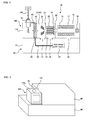
- Fig 1 is a schematic diagram showing an example of the structure of a liquid chromatograph mass spectrometer using an ESI method according to the present invention.
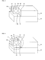
- Figs 2 through 4 are perspective diagrams showing the liquid chromatograph mass spectrometer of Fig 1 .
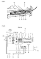
- Fig 5 is a perspective diagram showing an enlargement of A in Fig 4 .
- Fig 2 is a diagram wherein the ionization chamber is put into the analysis position.
- Fig 3 is a diagram wherein the ionization chamber is put into the maintenance position.
- Figs 4 and 5 are diagrams wherein the ionization chamber is being moved.
- the same symbols as in the above described conventional liquid chromatograph mass spectrometer are attached to the corresponding components in the drawings.
- the liquid chromatograph mass spectrometer has an ionization chamber 100, a mass spectrometric unit 50 and a control chamber 60.
- the mass spectrometric unit 50 has a housing 90 made of aluminum in a rectangular parallelepiped for of 15 cm ⁇ 15 cm ⁇ 90 cm, wherein a first ion lens 21 is provided inside of the first middle chamber 12 and, at the same time, a discharge opening 31 for vacuum discharge by means of an oil-sealed rotary pump (RP) is provided beneath the first middle chamber 12.
- RP oil-sealed rotary pump
- a heater block 20 having a built-in temperature adjustment mechanism (not shown) is fixed to the front surface of the housing 90 and a solvent removal tube 19 in a circular tubular form (an outer diameter of 1.6 mm and an inner diameter of 0.5 mm) is created in the heater block 20.
- a solvent removal tube 19 in a circular tubular form an outer diameter of 1.6 mm and an inner diameter of 0.5 mm
- a hole 91 is created in the upper right portion of the front surface of the housing 90 in the horizontal direction (toward the rear).
- Fig 6(b) is a cross sectional diagram showing an enlargement of the mass spectrometric unit side voltage contact point 92.
- the mass spectrometric unit side voltage contact point 92 has a socket 93 made of a metal and a cylinder 94 made of a resin (insulating material).
- the socket 93 made of a metal is a cylinder having an outer diameter of 4 mm and an inner diameter of 2 mm, for example, and is placed inside of the hole 91 so that the center axis of the socket 93 made of a metal and the center axis of the hole 91 become in approximate agreement.
- the front side of the front cylinder 94c is tapered around the outer periphery so as to provide a tapered portion 94a where the outer diameter becomes gradually smaller towards the front.
- a flange 94b is formed so as to protrude from the outer periphery of the rear cylinder 94d in the radius direction on the rear side so that the mass spectrometric unit side voltage contact point 92 is fixed so as not to move in the front to rear direction.
- a control chamber 60 is provided beneath the ionization chamber 100 and has a control chamber housing 61 in a rectangular parallelepiped form.
- a high voltage power supply 62 is provided inside the control chamber housing 61.
- one end portion of the cable 63 is connected to the high voltage power supply 62 inside the control chamber housing 61 and, at the same time, the other end portion of the cable 63 is connected to the rear of the socket 93 made of a metal formed within the housing 90.
- the ionization chamber 100 has a compartment 110 made of aluminum in a rectangular parallelepiped form of 13 cm ⁇ 13 cm ⁇ 12 cm and the compartment 110 has an upper surface 110a, a rear surface 110b, a front surface, a right surface, a left surface and a lower surface.
- a circular opening 102 is created in the center portion of the rear surface 110b, and the periphery portion of the opening 102 in the rear surface 110b is attached in an airtight manner to the front surface of the first middle chamber 12 via an O ring made of rubber (not shown).
- an ionization chamber side voltage contact point 80 is formed in the upper right portion of the rear surface 110b so as to protrude in the horizontal direction (toward the rear) by 10 mm or more and 11 mm or less, for example.
- Fig 6(a) is a cross sectional diagram showing an enlargement of the ionization chamber side voltage contact point 80.
- the ionization chamber side voltage contact point 80 has a cylinder 82 made of a resin (insulating material) and a plug 81 made of a metal.
- the plug 81 made of a metal is approximately in a columnar form having a diameter of 2 mm, for example, and is placed inside the cylinder 82 so that the center axis of the plug 81 made of a metal and the center axis of the cylinder 82 are in approximate agreement.
- the distance (R 5 - R 1 ) is preferable for the distance (R 5 - R 1 ) to be 0.5 mm or more and 3 mm or less.
- the front side of the plug 81 made of a metal is connected to the spray unit 15 via a cable 64, and the plug 81 made of a metal can be inserted into and engaged with the socket 93 made of a metal for connection.
- the spray unit (ionization unit) 15 is attached to the upper surface 110a of the compartment 110.
- the liquid sample separated into components by the LC unit is supplied to the spray unit 15 via a pipe 155.
- nebulizing gas nitrogen gas
- a nebulizing gas supply source via a pipe having a diameter of 3.2 mm, for example.
- the plug 81 made of a metal connected to the spray unit 15 and the socket 93 made of a metal connected to the high voltage power supply 62 are connected to each other so that a high voltage of 5 kV is applied from the high voltage power supply 62 to the tip of the nozzle of the spray unit 15 and, thus, ionization can be achieved.
- the ionization chamber 100 can be moved between the maintenance position and the analysis position.
- the ionization chamber 100 is rotatable by approximately 90° around an axis of one side between the rear surface 110b and the front surface of the first middle chamber 12 in the vertical direction by means of a hinge 101.
- the user can put the ionization chamber 100 into the maintenance position in order to maintain the first ion lens 21 and the like, or put the ionization chamber 100 into the analysis position in order to carry out analysis.
- the ionization chamber 100 is put into the maintenance position wherein the front surface of the first middle chamber 12 is open. At this time, the socket 93 made of a metal and the plug 81 made of a metal are disconnected from each other.
- the ionization chamber side voltage contact point 80 is inserted into the hole 91.
- the cylinder 82 having the outer diameter R 1 is inserted into the front hole 91a having the diameter R 5 so that the tapered portion 82a of the cylinder 82 makes contact with the tapered portion 94a of the front cylinder 94c.
- a predetermined distance ((R 3 - R 4 )/2) provided between the inner periphery of the rear hole 91b and the outer periphery of the rear cylinder 94d allows the rear cylinder 94d to move only by the distance (R 3 - R 4 ) in the radius direction and, thus, allows the ionization chamber 100 to rotate smoothly even in the case wherein there is a positional misalignment in the radius direction between the ionization chamber side voltage contact point 80 and the mass spectrometric unit side voltage contact point 92. Therefore, the plug 81 made of a metal is inserted into and engaged with the socket 93 made of a metal while the inner periphery of the cylinder 82 makes contact with the outer periphery of the front cylinder 94c.
- the ionization chamber 100 is put into the analysis position wherein the periphery portion of the opening 102 in the rear surface 110b is attached to the front surface of the first middle chamber 12 in an airtight manner.
- the socket 93 made of a metal and the plug 81 made of a metal are connected to each other.
- Fig 7 is a cross sectional diagram showing an enlargement of the socket 93 made of a metal and the plug 81 made of a metal when connected to each other.
- the spray unit 15 and the high voltage power supply 62 are automatically connected to each other when the ionization chamber 100 is put into the analysis position and the spray unit 15 and the high voltage power supply 62 are automatically disconnected when the ionization chamber 100 is put into the maintenance position. Therefore, costs can be lowered and, in addition, ease of maintenance can be improved.
- the above described liquid chromatograph mass spectrometer has such a structure that the mass spectrometric unit side voltage contact point 92 has a socket 93 made of a metal and, at the same time, the ionization chamber side voltage contact point 80 has a plug 81 made of a metal
- the structure may allow the mass spectrometric unit side voltage contact point to have a plug made of a metal and may allow the ionization chamber side voltage contact point to have a socket made of a metal.
- the present invention can be applied to mass spectrometers having an ionization chamber.
Landscapes
- Chemical & Material Sciences (AREA)
- Analytical Chemistry (AREA)
- Other Investigation Or Analysis Of Materials By Electrical Means (AREA)
- Electron Tubes For Measurement (AREA)
Abstract
Description
- The present invention relates to a mass spectrometer having an ionization chamber and, in particular, to a liquid chromatograph mass spectrometer having an ionization chamber for ionizing a liquid sample that has been eluted from a liquid chromatographic unit and a mass spectrometric unit into which ions are introduced from the ionization chamber.
- Liquid chromatograph mass spectrometers (LC/MS) are formed of a liquid chromatographic unit (LC unit) for separating a liquid sample into components, each of which is eluted, an ionization chamber (interface unit) for ionizing a sample component that has been eluted from the LC unit and a mass spectrometric unit (MS unit) for detecting ions that have been introduced from the ionization chamber. In such an ionization chamber various ionization techniques for ionizing a liquid sample are used and, in particular, atmospheric pressure ionization methods, such as the atmospheric pressure chemical ionization method (APCI) and the electrospray ionization method (ESI), are widely used.
- Concretely, in the APCI the tip of a nozzle connected to the end of the column in the LC unit is placed so as to be directed toward the inside of the ionization chamber and, at the same time, a needle electrode is provided in front of the tip of the nozzle. Thus, a droplet of a sample that has been atomized through heating in the nozzle is made to chemically react with carrier gas ions (buffer ions) generated through corona discharge from the needle electrode so as to be ionized. In addition, in the ESI the tip of the nozzle connected to the end of the column in the LC unit is placed so as to be directed towards the inside of the ionization chamber and, at the same time, a high voltage of approximately 5 kV is applied to the tip portion of the nozzle so that a strong non-uniform electrical field is generated. As a result, the liquid sample is subjected to charge separation by means of the electrical field and, thus, is torn apart through Coulomb attraction so as to be atomized. As a consequence, the solvent in the droplet of the sample evaporates through contact with the surrounding air and, thus, gas ions are generated.
- As described above, in the APCI and ESI, the liquid sample is ionized in a state that is close to atmospheric pressure and, therefore, a structure is adopted such that a middle chamber is provided between the ionization chamber and the MS unit so that the degree of vacuum can be increased step by step in order to maintain a difference in pressure between the ionization chamber in a high pressure state (that is, a state close to atmospheric pressure) and the MS unit in a very low pressure state (that is, a state of a vacuum of a high degree) (see Patent Document 1).
- The applicant has announced on Internet websites technologies for increasing the sensitivity in and the ease of maintenance of a liquid chromatograph mass spectrometer (see Non-patent Documents 1 to 4).
-
Fig 8 is a schematic diagram showing an example of the structure of a liquid chromatograph mass spectrometer using an ESI method.Fig 9 is a perspective diagram showing the liquid chromatograph mass spectrometer ofFig 8 . - The liquid chromatograph mass spectrometer has an
ionization chamber 200, a massspectrometric unit 50, acontrol chamber 160 and ahousing unit 170. - The
ionization chamber 200 has acompartment 210 in a triangular prismatic form made of aluminum, and thecompartment 210 has anupper surface 210a, a first side, a second side, a third side and a lower surface. In addition, a circular opening is created in the center portion of the first side and the peripheral portion of the opening in the first side is attached in an airtight manner to the front surface of afirst middle chamber 12 via an O ring made of rubber (not shown). Furthermore, a spray unit (ionization member) 15 is attached to theupper surface 210a of thecompartment 210. - The
control chamber 160 is located beneath theionization chamber 200 and has acontrol chamber housing 161 in a rectangular parallelepiped form wherein a highvoltage power supply 62 is provided inside of thecontrol chamber housing 161. In addition, one end portion of acable 63 is connected to the highvoltage power supply 62 inside of thecontrol chamber housing 161 and, at the same time, the other end portion of thecable 63 is connected to aconnector 65, which is placed outside of thecontrol chamber housing 161. - The liquid sample that has been separated into components in the LC unit is supplied to the
spray unit 15 through apipe 155. Though not shown, a nebulizing gas (nitrogen gas) is supplied to thespray unit 15 from a nebulizing gas supplying source through a pipe having a diameter of 3.2 mm for example. As a result, the liquid sample and the nebulizing gas are led to thespray unit 15 so as to be sprayed. At this time aconnector 67 of acable 64 connected to thespray unit 15 and theconnector 65 of thecable 63 connected to the highvoltage power supply 62 are connected to each other so that a high voltage of 5 kV is applied to the tip of the nozzle of thespray unit 15 from the highvoltage power supply 62 and, thus, ionization can be achieved. - Though
Fig 8 shows aspray unit 15 for ESI, generally thespray unit 15 is removable from thecompartment 210 and in the case wherein the APCI method is used, thespray unit 15 for ESI is removed and instead a spray unit for APCI where a needle electrode for discharge can be treated as a unit is attached to thecompartment 210. - The mass
spectrometric unit 50 is provided with a first middle chamber (vacuum introduction unit) 12 that is adjacent to theionization chamber 200, asecond middle chamber 13 that is adjacent to thefirst middle chamber 12 and a mass spectrometric chamber (MS unit) that is adjacent to thesecond middle chamber 13 in a manner wherein these chambers are connected to each with respective partitions there between. - The mass
spectrometric unit 50 is provided with ahousing 190 made of aluminum in a parallelepiped form of 15 cm × 15 cm × 90 cm, wherein afirst ion lens 21 is provided inside thefirst middle chamber 12 and, at the same time, a discharge opening 31 for vacuum discharge by means of an oil-sealed rotary pump (RP) is provided at the bottom of thefirst middle chamber 12. - A
heater block 20 having a built-in temperature adjustment mechanism (not shown) is fixed to the front surface of thehousing 190, where asolvent removal tube 19 in a circular tubular form (an outer diameter of 1.6 mm and an inner diameter of 0.5 mm) is formed in theheater block 20. As a result, the inside of thecompartment 210 and the inside of thehousing 190 are connected to each other via thesolvent removal tube 19. Therefore, thesolvent removal tube 19 has such functions that removal of solvent and ionization are accelerated through heating and through collision when ions and fine droplets of the sample sprayed from thespray unit 15 pass through the inside thereof. - An
octupole 23 and afocus lens 24 are provided inside thesecond middle chamber 13, and adischarge opening 32 for vacuum discharge by means of a turbo molecular pump (TMP) is provided beneath thesecond middle chamber 13. Anentry lens 25 having a small hole is provided in the partition between thesecond middle chamber 13 and the massspectrometric chamber 14 so that the inside of thesecond middle chamber 13 and the inside of the massspectrometric chamber 14 are connected via this small hole. - A
first quadrupole 16, asecond quadrupole 17 and adetector 18 are provided inside the massspectrometric chamber 14 and adischarge opening 33 for vacuum discharge by means of the turbo molecular pump (TMP) is provided at the bottom of the massspectrometric chamber 14. - In this liquid chromatograph mass spectrometer, ions generated in the
ionization chamber 200 are sent to the massspectrometric chamber 14 after passing through thesolvent removal tube 19, thefirst ion lens 21 within thehousing 190 in thefirst middle chamber 12, askimmer 22, theoctupole 23 and thefocus lens 24 within thesecond middle chamber 13, and theentry lens 25 in this order, where unnecessary ions are discharged by means ofquadrupoles detector 18 are detected. - Incidentally, in the above described liquid chromatograph mass spectrometer, the
first ion lens 21 and the like require maintenance and, therefore, the structure allows theionization chamber 200 to be treated as a unit so that theionization chamber 200 can be moved between the maintenance position and the analysis position. For example, theionization chamber 200 is rotatable by approximately 90° around the axis along the side between the first side and the front of thefirst middle chamber 12 in the vertical direction by means of a hinge (not shown). As a result, the user disconnects theconnector 67 of thecable 64 connected to thespray unit 15 from theconnector 65 of thecable 63 connected to the highvoltage power supply 62 and removes thespray unit 15 in order to maintain thefirst ion lens 21 and the like and, after that, puts theionization chamber 200 in the maintenance position and attaches thespray unit 15 for spectrometry followed by reconnection between theconnector 67 of thecable 64 connected to thespray unit 15 and theconnector 65 of thecable 63 connected to the highvoltage power supply 62 and, then, puts theionization chamber 200 in the analysis position. - Patent Document 1: Japanese Unexamined Patent Publication
2001-343363 -
- Non-patent Document 1:
- http://www.shimadzu.co.jp/news/press/n00kbc00000038uu.html
- Non-patent Document 2:
- http://www.an.shimadzu.co.jp/lcms/lcms8050/index.htm
- Non-patent Document 3:
- http://www.an.shimadzu.co.jp/lcms/lcms8050/uf-technology.htm
- Non-patent Document 4:
- http://www.an.shimadzu.co.jp/lcms/lcms8050/product-design.htm
- In the liquid chromatograph mass spectrometer as described above, it is necessary to connect and disconnect the
connector 65 to and from theconnector 67 for switching between the spray for ESI and the spray for APCI or for maintenance or spectrometry, which is quite troublesome and takes a long time and, thus, becomes a problem. - In order to solve the above described problem the present inventor examined the possibility of a liquid chromatograph mass spectrometer wherein the
spray unit 15 and the highvoltage power supply 62 are automatically connected to each other when theionization chamber 200 is put in the analysis position and thespray unit 15 and the highvoltage power supply 62 are automatically disconnected from each other when theionization chamber 200 is put in the maintenance position. A high voltage is applied to thespray unit 15 and, therefore, the voltage contact point needs a creepage distance and an air clearance. Meanwhile, it is costly to increase the number of parts to provide such a mechanism. - Therefore, the inventor discovered it effective to form an ionization chamber side voltage contact point in a compartment of the ionization chamber and to form a mass spectrometric unit side voltage contact point in the hole created in the housing of the mass spectrometric unit. The inventor also discovered that a predetermined distance (gap) is provided between the inner periphery of the hole and outer periphery of the mass spectrometric unit side voltage contact point so that the mass spectrometric unit side voltage contact point can freely move by the same distance as the gap and, thus, the positional misalignment between the ionization chamber side voltage contact point and the mass spectrometric unit side voltage contact point can be tolerated (floating structure).
- The mass spectrometer according to the present invention is a mass spectrometer provided with an ionization chamber having an ionization unit for ionizing a sample, a mass spectrometric unit to which ions are introduced from the above described ionization chamber and a power supply for supplying power to the above described ionization unit, wherein the above described ionization chamber can be moved to a maintenance position for maintaining the above described mass spectrometric unit and to a analysis position for analyzing the above described sample, an ionization chamber side voltage contact point is formed in a compartment of the above described ionization chamber so as to protrude, a mass spectrometric unit side voltage contact point is formed in a hole created in a housing of the above described mass spectrometric unit, a predetermined distance is provided between the inner periphery of the above described hole and the outer periphery of the above described mass spectrometric unit side voltage contact point, and the above described ionization chamber side voltage contact point is inserted into the above described hole so as to be connected to the above described mass spectrometric unit side voltage contact point when the above described ionization chamber is put into the above described analysis position and the above described ionization chamber side voltage contact point is pulled out from the above described hole so as to be disconnected from the above described mass spectrometric unit side voltage contact point when the above described ionization chamber is put into the above described maintenance position.
- Here, a "predetermined distance" is a distance that makes it possible for the ionization chamber side voltage contact point to be inserted into the hole when the mass spectrometric unit side voltage contact point moves even in the case wherein there is a slight positional misalignment between the ionization chamber side voltage contact point and the mass spectrometric unit side voltage contact point when the ionization chamber is moved from the maintenance position to the analysis position and is determined through orbit calculation and the like by the designer. For example, it is preferable for a distance of 0.25 mm or more and 1.5 mm or less to be provided between the inner periphery of the hole and the outer periphery of the mass spectrometric unit side voltage contact point.
- As describe above, in the mass spectrometer according to the present invention, which is made of a small number of parts, the ionization unit and the power supply are automatically connected to each other when the ionization chamber is put into the analysis position and the ionization unit and the power supply are automatically from each other when the ionization chamber is put into the maintenance position. As a result, costs can be reduced and, in addition, ease of maintenance can be improved. In addition, a predetermined distance (gap) is provided between the inner periphery of the hole and the outer periphery of the mass spectrometric unit side voltage contact point so that the mass spectrometric unit side voltage contact point can freely move by the same distance as the gap and, thus, the ionization chamber can be moved smoothly even in the case wherein there is a positional misalignment between the ionization chamber side voltage contact point and the mass spectrometric unit side voltage contact point.
- In addition, in the mass spectrometer according to the present invention, the above described ionization chamber may be provided with a compartment in a rectangular parallelepiped form having a rear surface linked to the front surface of the housing of the above described mass spectrometric unit, an upper surface, a front surface, a right surface, a left surface and a lower surface, the above described ionization chamber may be rotatable around an axis of a side of the above described rear surface in the vertical direction, the above described ionization chamber side voltage contact point may be formed so as to protrude from the rear surface of the above described compartment in the horizontal direction, and the above described mass spectrometric unit side voltage contact point may be formed in a hole created in the front surface of the above described housing in the horizontal direction.
- Furthermore, in the mass spectrometer according to the present invention, the above described ionization chamber side voltage contact point may be a plug made of a metal and, at the same time, the above described mass spectrometric unit side voltage contact point may be a socket made of a metal, or the above described ionization chamber side voltage contact point may be a socket made of a metal and, at the same time, the above described mass spectrometric unit side voltage contact point may be a plug made of a metal, and the above described plug made of a metal may be placed inside a cylinder formed of an insulating material and, at the same time, the outer periphery of the above described socket made of a metal may be covered by a cylinder formed of an insulating material.
-
-
Fig 1 is a schematic diagram showing an example of the structure of a liquid chromatograph mass spectrometer using an ESI method according to the present invention; -
Fig 2 is a perspective diagram showing the liquid chromatograph mass spectrometer ofFig 1 ; -
Fig 3 is a perspective diagram showing the liquid chromatograph mass spectrometer ofFig 1 ; -
Fig 4 is a perspective diagram showing the liquid chromatograph mass spectrometer ofFig 1 ; -
Fig 5 is a perspective diagram showing an enlargement of A inFig 4 ; -
Figs 6(a) and 6(b) are cross sectional diagrams showing enlargements of the ionization chamber side voltage contact point and the mass spectrometric unit side voltage contact point; -
Fig 7 is a cross sectional diagram showing an enlargement of the socket made of a metal and a plug made of a metal when connected; -
Fig 8 is a schematic diagram showing an example of the structure of a general liquid chromatograph mass spectrometer using an ESI method; and -
Fig 9 is a perspective diagram showing the liquid chromatograph mass spectrometer ofFig 8 . - In the following the embodiments of the present invention are described in reference to the drawings. Here, the present invention is not limited to the below described embodiments but includes, of course, various modifications as long as the gist of the present invention is not deviated from.
-
Fig 1 is a schematic diagram showing an example of the structure of a liquid chromatograph mass spectrometer using an ESI method according to the present invention.Figs 2 through 4 are perspective diagrams showing the liquid chromatograph mass spectrometer ofFig 1 .Fig 5 is a perspective diagram showing an enlargement of A inFig 4 . Here,Fig 2 is a diagram wherein the ionization chamber is put into the analysis position.Fig 3 is a diagram wherein the ionization chamber is put into the maintenance position.Figs 4 and5 are diagrams wherein the ionization chamber is being moved. In addition, the same symbols as in the above described conventional liquid chromatograph mass spectrometer are attached to the corresponding components in the drawings. - The liquid chromatograph mass spectrometer has an
ionization chamber 100, a massspectrometric unit 50 and acontrol chamber 60. - The mass
spectrometric unit 50 has ahousing 90 made of aluminum in a rectangular parallelepiped for of 15 cm × 15 cm × 90 cm, wherein afirst ion lens 21 is provided inside of the firstmiddle chamber 12 and, at the same time, adischarge opening 31 for vacuum discharge by means of an oil-sealed rotary pump (RP) is provided beneath the firstmiddle chamber 12. - A
heater block 20 having a built-in temperature adjustment mechanism (not shown) is fixed to the front surface of thehousing 90 and asolvent removal tube 19 in a circular tubular form (an outer diameter of 1.6 mm and an inner diameter of 0.5 mm) is created in theheater block 20. As a result the inside of thecompartment 110 and the inside of thehousing 90 are connected to each other via thesolvent removal tube 19. - In addition, a
hole 91 is created in the upper right portion of the front surface of thehousing 90 in the horizontal direction (toward the rear). Thehole 91 has a two-step structure consisting of afront hole 91a having a diameter R5 = 11 mm and arear hole 91b having a diameter R3 = 10 mm, and a mass spectrometric unit sidevoltage contact point 92 is provided inside of thehole 91.Fig 6(b) is a cross sectional diagram showing an enlargement of the mass spectrometric unit sidevoltage contact point 92. - The mass spectrometric unit side
voltage contact point 92 has asocket 93 made of a metal and acylinder 94 made of a resin (insulating material). Thesocket 93 made of a metal is a cylinder having an outer diameter of 4 mm and an inner diameter of 2 mm, for example, and is placed inside of thehole 91 so that the center axis of thesocket 93 made of a metal and the center axis of thehole 91 become in approximate agreement. In addition, thecylinder 94 has a two-step structure consisting of afront cylinder 94c having an outer diameter R2 = 6 mm and an inner diameter of 4 mm and arear cylinder 94d having an outer diameter R4 = 8 mm and an inner diameter of 5 mm and, thus, covers the outer periphery of thesocket 93 made of a metal. That is to say, a predetermined distance ((R3 - R4)/2) is provided between the inner periphery of therear hole 91b and the outer periphery of therear cylinder 94d so that the mass spectrometric unit sidevoltage contact point 92 can move by the distance (R3 - R4) in the direction of the radius (floating structure). It is preferable for this distance (R3 - R4) to be 0.5 mm or more and 3 mm or less. - Here, the front side of the
front cylinder 94c is tapered around the outer periphery so as to provide a taperedportion 94a where the outer diameter becomes gradually smaller towards the front. In addition, aflange 94b is formed so as to protrude from the outer periphery of therear cylinder 94d in the radius direction on the rear side so that the mass spectrometric unit sidevoltage contact point 92 is fixed so as not to move in the front to rear direction. - A
control chamber 60 is provided beneath theionization chamber 100 and has acontrol chamber housing 61 in a rectangular parallelepiped form. A highvoltage power supply 62 is provided inside thecontrol chamber housing 61. In addition, one end portion of thecable 63 is connected to the highvoltage power supply 62 inside thecontrol chamber housing 61 and, at the same time, the other end portion of thecable 63 is connected to the rear of thesocket 93 made of a metal formed within thehousing 90. - The
ionization chamber 100 has acompartment 110 made of aluminum in a rectangular parallelepiped form of 13 cm × 13 cm × 12 cm and thecompartment 110 has anupper surface 110a, arear surface 110b, a front surface, a right surface, a left surface and a lower surface. In addition, acircular opening 102 is created in the center portion of therear surface 110b, and the periphery portion of theopening 102 in therear surface 110b is attached in an airtight manner to the front surface of the firstmiddle chamber 12 via an O ring made of rubber (not shown). - In addition, an ionization chamber side
voltage contact point 80 is formed in the upper right portion of therear surface 110b so as to protrude in the horizontal direction (toward the rear) by 10 mm or more and 11 mm or less, for example.Fig 6(a) is a cross sectional diagram showing an enlargement of the ionization chamber sidevoltage contact point 80. - The ionization chamber side
voltage contact point 80 has acylinder 82 made of a resin (insulating material) and aplug 81 made of a metal. Thecylinder 82 has an outer diameter R1 = 10 mm and an inner diameter R2 = 6 mm, for example, and atapered portion 82a of which the inner diameter increases gradually towards the rear is provided around the inner periphery on the rear side. In addition, theplug 81 made of a metal is approximately in a columnar form having a diameter of 2 mm, for example, and is placed inside thecylinder 82 so that the center axis of theplug 81 made of a metal and the center axis of thecylinder 82 are in approximate agreement. - Here, it is preferable for the distance (R5 - R1) to be 0.5 mm or more and 3 mm or less. In addition, the front side of the
plug 81 made of a metal is connected to thespray unit 15 via acable 64, and theplug 81 made of a metal can be inserted into and engaged with thesocket 93 made of a metal for connection. - The spray unit (ionization unit) 15 is attached to the
upper surface 110a of thecompartment 110. The liquid sample separated into components by the LC unit is supplied to thespray unit 15 via apipe 155. Though not shown, nebulizing gas (nitrogen gas) is supplied to thespray unit 15 from a nebulizing gas supply source via a pipe having a diameter of 3.2 mm, for example. As a result, the liquid sample and the nebulizing gas are led to thespray unit 15 so as to be sprayed. At this time, theplug 81 made of a metal connected to thespray unit 15 and thesocket 93 made of a metal connected to the highvoltage power supply 62 are connected to each other so that a high voltage of 5 kV is applied from the highvoltage power supply 62 to the tip of the nozzle of thespray unit 15 and, thus, ionization can be achieved. - In addition, the
ionization chamber 100 can be moved between the maintenance position and the analysis position. Concretely, theionization chamber 100 is rotatable by approximately 90° around an axis of one side between therear surface 110b and the front surface of the firstmiddle chamber 12 in the vertical direction by means of ahinge 101. As a result, the user can put theionization chamber 100 into the maintenance position in order to maintain thefirst ion lens 21 and the like, or put theionization chamber 100 into the analysis position in order to carry out analysis. - Here, the analysis state (normal usage state) and the maintenance state (during maintenance of the mass spectrometric unit) of the liquid chromatograph mass spectrometer according to the present invention are described.
- The
ionization chamber 100 is put into the maintenance position wherein the front surface of the firstmiddle chamber 12 is open. At this time, thesocket 93 made of a metal and theplug 81 made of a metal are disconnected from each other. - As the
ionization chamber 100 is rotated from the maintenance position to the analysis position, the ionization chamber sidevoltage contact point 80 is inserted into thehole 91. Concretely, thecylinder 82 having the outer diameter R1 is inserted into thefront hole 91a having the diameter R5 so that the taperedportion 82a of thecylinder 82 makes contact with the taperedportion 94a of thefront cylinder 94c. At this time, a predetermined distance ((R3 - R4)/2) provided between the inner periphery of therear hole 91b and the outer periphery of therear cylinder 94d allows therear cylinder 94d to move only by the distance (R3 - R4) in the radius direction and, thus, allows theionization chamber 100 to rotate smoothly even in the case wherein there is a positional misalignment in the radius direction between the ionization chamber sidevoltage contact point 80 and the mass spectrometric unit sidevoltage contact point 92. Therefore, theplug 81 made of a metal is inserted into and engaged with thesocket 93 made of a metal while the inner periphery of thecylinder 82 makes contact with the outer periphery of thefront cylinder 94c. - The
ionization chamber 100 is put into the analysis position wherein the periphery portion of theopening 102 in therear surface 110b is attached to the front surface of the firstmiddle chamber 12 in an airtight manner. At this time, thesocket 93 made of a metal and theplug 81 made of a metal are connected to each other.Fig 7 is a cross sectional diagram showing an enlargement of thesocket 93 made of a metal and theplug 81 made of a metal when connected to each other. - As described above, in the liquid chromatograph mass spectrometer according to the present invention, which has a small number of parts, the
spray unit 15 and the highvoltage power supply 62 are automatically connected to each other when theionization chamber 100 is put into the analysis position and thespray unit 15 and the highvoltage power supply 62 are automatically disconnected when theionization chamber 100 is put into the maintenance position. Therefore, costs can be lowered and, in addition, ease of maintenance can be improved. - Though the above described liquid chromatograph mass spectrometer has such a structure that the mass spectrometric unit side
voltage contact point 92 has asocket 93 made of a metal and, at the same time, the ionization chamber sidevoltage contact point 80 has aplug 81 made of a metal, the structure may allow the mass spectrometric unit side voltage contact point to have a plug made of a metal and may allow the ionization chamber side voltage contact point to have a socket made of a metal. - The present invention can be applied to mass spectrometers having an ionization chamber.
-
- 15: spray unit (ionization unit)
- 19: solvent removal tube
- 50: mass spectrometric unit
- 60: control chamber
- 61: control chamber housing
- 62: high voltage power supply
- 80: ionization chamber side voltage contact point
- 90: housing
- 91: hole
- 92: mass spectrometric unit side voltage contact point
- 100: ionization chamber
- 110: compartment
Claims (3)
- A mass spectrometer, comprising an ionization chamber having an ionization unit for ionizing a sample, a mass spectrometric unit to which ions are introduced from said ionization chamber and a power supply for supplying power to said ionization unit, characterized in that
said ionization chamber can be moved to a maintenance position for maintaining said mass spectrometric unit and to an analysis position for analyzing said sample,
an ionization chamber side voltage contact point is formed in a compartment of said ionization chamber so as to protrude,
a mass spectrometric unit side voltage contact point is formed in a hole created in a housing of said mass spectrometric unit,
a predetermined distance is provided between the inner periphery of said hole and the outer periphery of said mass spectrometric unit side voltage contact point, and
said ionization chamber side voltage contact point is inserted into said hole so as to be connected to said mass spectrometric unit side voltage contact point when said ionization chamber is put into said analysis position and said ionization chamber side voltage contact point is pulled out from said hole so as to be disconnected from said mass spectrometric unit side voltage contact point when said ionization chamber is put into said maintenance position. - The mass spectrometer according to Claim 1, characterized in that
said ionization chamber comprises a compartment in a rectangular parallelepiped form having a rear surface linked to the front surface of the housing of said mass spectrometric unit, an upper surface, a front surface, a right surface, a left surface and a lower surface,
said ionization chamber is rotatable around an axis of a side of said rear surface in the vertical direction,
said ionization chamber side voltage contact point is formed so as to protrude from the rear surface of said compartment in the horizontal direction, and
said mass spectrometric unit side voltage contact point is formed in a hole created in the front surface of said housing in the horizontal direction. - The mass spectrometer according to Claim 1 or 2, characterized in that
said ionization chamber side voltage contact point is a plug made of a metal and, at the same time, said mass spectrometric unit side voltage contact point is a socket made of a metal, or said ionization chamber side voltage contact point is a socket made of a metal and, at the same time, said mass spectrometric unit side voltage contact point is a plug made of a metal, and
said plug made of a metal is placed inside a cylinder formed of an insulating material and, at the same time, the outer periphery of said socket made of a metal is covered by a cylinder formed of an insulating material.
Applications Claiming Priority (1)
| Application Number | Priority Date | Filing Date | Title |
|---|---|---|---|
| JP2013181822A JP6044494B2 (en) | 2013-09-03 | 2013-09-03 | Mass spectrometer |
Publications (2)
| Publication Number | Publication Date |
|---|---|
| EP2843685A2 true EP2843685A2 (en) | 2015-03-04 |
| EP2843685A3 EP2843685A3 (en) | 2015-04-01 |
Family
ID=50979641
Family Applications (1)
| Application Number | Title | Priority Date | Filing Date |
|---|---|---|---|
| EP14173538.1A Withdrawn EP2843685A3 (en) | 2013-09-03 | 2014-06-23 | Mass spectrometer |
Country Status (4)
| Country | Link |
|---|---|
| US (1) | US8927929B1 (en) |
| EP (1) | EP2843685A3 (en) |
| JP (1) | JP6044494B2 (en) |
| CN (1) | CN104425203B (en) |
Cited By (1)
| Publication number | Priority date | Publication date | Assignee | Title |
|---|---|---|---|---|
| US12308223B2 (en) | 2019-11-28 | 2025-05-20 | Shimadzu Corporation | Mass spectrometer |
Families Citing this family (6)
| Publication number | Priority date | Publication date | Assignee | Title |
|---|---|---|---|---|
| US9633826B1 (en) * | 2016-03-15 | 2017-04-25 | Shimadzu Corporation | Mass spectrometer with movable ionization chamber |
| EP3729487B1 (en) * | 2017-12-22 | 2025-09-17 | Micromass UK Limited | Device for rapid exchange of ion sources and ion transmission devices |
| WO2019234919A1 (en) * | 2018-06-08 | 2019-12-12 | 株式会社島津製作所 | Probe electrospray ionization unit and ion analysis device |
| JP7196823B2 (en) * | 2019-11-20 | 2022-12-27 | 株式会社島津製作所 | Mass spectrometer |
| JPWO2024157847A1 (en) * | 2023-01-27 | 2024-08-02 | ||
| GB2628563B (en) * | 2023-03-28 | 2026-03-11 | Thermo Fisher Scient Bremen Gmbh | Chromatography interface |
Citations (2)
| Publication number | Priority date | Publication date | Assignee | Title |
|---|---|---|---|---|
| JP2001343363A (en) | 2000-06-05 | 2001-12-14 | Shimadzu Corp | Mass spectrometer |
| WO2013044232A1 (en) * | 2011-09-22 | 2013-03-28 | Purdue Research Foundation | Differentially pumped dual linear quadrupole ion trap mass spectrometer |
Family Cites Families (21)
| Publication number | Priority date | Publication date | Assignee | Title |
|---|---|---|---|---|
| US4388531A (en) * | 1981-03-06 | 1983-06-14 | Finnigan Corporation | Ionizer having interchangeable ionization chamber |
| US4447728A (en) * | 1982-02-05 | 1984-05-08 | Finnigan Corporation | Ionizer including discharge ion source and method |
| JP2953344B2 (en) * | 1995-04-28 | 1999-09-27 | 株式会社島津製作所 | Liquid chromatograph mass spectrometer |
| JP3128053B2 (en) * | 1995-05-30 | 2001-01-29 | 株式会社島津製作所 | Gas chromatograph mass spectrometer |
| US5753795A (en) * | 1996-05-10 | 1998-05-19 | Hewlett-Packard Company | Demountable vacuum-sealing plate assembly |
| JP4267223B2 (en) * | 1996-08-30 | 2009-05-27 | 株式会社日立製作所 | Mass spectrometer |
| US6331713B1 (en) * | 1999-10-06 | 2001-12-18 | Applied Materials, Inc. | Movable ion source assembly |
| US6525313B1 (en) * | 2000-08-16 | 2003-02-25 | Brucker Daltonics Inc. | Method and apparatus for an electrospray needle for use in mass spectrometry |
| US7427750B2 (en) * | 2003-01-17 | 2008-09-23 | Griffin Analytical Technologies, L.L.C. | Mass spectrometer assemblies, mass spectrometry vacuum chamber lid assemblies, and mass spectrometer operational methods |
| US7388195B2 (en) * | 2004-09-30 | 2008-06-17 | Charles Stark Draper Laboratory, Inc. | Apparatus and systems for processing samples for analysis via ion mobility spectrometry |
| US7329865B2 (en) * | 2005-11-14 | 2008-02-12 | Agilent Technologies, Inc. | Mass spectrometry system and method with window assembly |
| WO2008087715A1 (en) * | 2007-01-17 | 2008-07-24 | Shimadzu Corporation | Ionization emitter, ionization apparatus, and process for producing ionization emitter |
| US7960711B1 (en) * | 2007-01-22 | 2011-06-14 | Chem-Space Associates, Inc. | Field-free electrospray nebulizer |
| EP2396803A4 (en) * | 2009-02-12 | 2016-10-26 | Ibis Biosciences Inc | Ionization probe assemblies |
| US8487239B2 (en) * | 2009-05-29 | 2013-07-16 | Micromass Uk Limited | Mass spectrometer |
| US8536522B2 (en) * | 2009-05-29 | 2013-09-17 | Micromass Uk Limited | Mass spectrometer |
| US8330101B2 (en) * | 2010-01-19 | 2012-12-11 | Agilent Technologies, Inc. | System and method for replacing an ion source in a mass spectrometer |
| JP5359926B2 (en) * | 2010-02-23 | 2013-12-04 | 株式会社島津製作所 | Mass spectrometer |
| DE102010037498B4 (en) * | 2010-09-13 | 2013-11-07 | Hachadorian Design & Calculation Gmbh | Electric contact |
| US8759757B2 (en) * | 2010-10-29 | 2014-06-24 | Thermo Finnigan Llc | Interchangeable ion source for electrospray and atmospheric pressure chemical ionization |
| JP5810984B2 (en) * | 2012-03-14 | 2015-11-11 | 株式会社島津製作所 | probe |
-
2013
- 2013-09-03 JP JP2013181822A patent/JP6044494B2/en active Active
-
2014
- 2014-06-05 US US14/296,844 patent/US8927929B1/en active Active
- 2014-06-23 EP EP14173538.1A patent/EP2843685A3/en not_active Withdrawn
- 2014-06-27 CN CN201410301678.3A patent/CN104425203B/en active Active
Patent Citations (2)
| Publication number | Priority date | Publication date | Assignee | Title |
|---|---|---|---|---|
| JP2001343363A (en) | 2000-06-05 | 2001-12-14 | Shimadzu Corp | Mass spectrometer |
| WO2013044232A1 (en) * | 2011-09-22 | 2013-03-28 | Purdue Research Foundation | Differentially pumped dual linear quadrupole ion trap mass spectrometer |
Non-Patent Citations (1)
| Title |
|---|
| SHIMADZU: "-introduces-lcms-8050-high-sensitivity- ultra-fast-triple-quadrupole-lc-msms Shimadzu Introduces the LCMS-8050 High-Sensitivity, Ultra-Fast Triple Quadrupole LC-MS/MS", 2 September 2013 (2013-09-02), XP055459283, Retrieved from the Internet <URL:https://www.shimadzu.nl/shimadzu-introduces-lcms-8050-high-sensitivity-ultra-fast-triple-quadrupole-lc-msms> [retrieved on 20180314] * |
Cited By (1)
| Publication number | Priority date | Publication date | Assignee | Title |
|---|---|---|---|---|
| US12308223B2 (en) | 2019-11-28 | 2025-05-20 | Shimadzu Corporation | Mass spectrometer |
Also Published As
| Publication number | Publication date |
|---|---|
| EP2843685A3 (en) | 2015-04-01 |
| JP2015050085A (en) | 2015-03-16 |
| US8927929B1 (en) | 2015-01-06 |
| CN104425203B (en) | 2017-04-12 |
| JP6044494B2 (en) | 2016-12-14 |
| CN104425203A (en) | 2015-03-18 |
Similar Documents
| Publication | Publication Date | Title |
|---|---|---|
| US8927929B1 (en) | Mass spectrometer | |
| JP7156553B2 (en) | Mass spectrometer | |
| EP3047510B1 (en) | Tool free gas cone retaining device for mass spectrometer ion block assembly | |
| CN107667414B (en) | Mass filter with extended operational life, mass spectrometer and method of mass filtering ions | |
| CN110024076B (en) | Ionization device and mass spectrometer | |
| US9305759B2 (en) | Ionization at intermediate pressure for atmospheric pressure ionization mass spectrometers | |
| JP6136773B2 (en) | Ionization probe | |
| EP2783387B1 (en) | Mass spectrometer system with curtain gas flow | |
| US7547891B2 (en) | Ion sampling apparatuses in fast polarity-switching ion sources | |
| EP3047507B1 (en) | Interface for ion source and vacuum housing | |
| US9008496B2 (en) | Probe | |
| JP6734874B2 (en) | Double bending ion guide and device using the same | |
| JP2019211440A (en) | Ion mobility analyzer | |
| US9396920B2 (en) | Ionization chamber | |
| US11043368B2 (en) | Method for ionizing gaseous samples by means of a dielectric barrier discharge and for subsequently analyzing the produced sample ions in an analysis appliance | |
| JP7294535B2 (en) | ion analyzer | |
| JPWO2019049272A1 (en) | Ion source and ion analyzer | |
| US10957526B2 (en) | Spatial, mass and energy focused ion injection method and device | |
| CN117476435A (en) | Novel composite ion source and mass spectrometer | |
| US9633826B1 (en) | Mass spectrometer with movable ionization chamber | |
| GB2520152A (en) | Tool free gas cone retaining device for mass spectrometer ion block assembly | |
| GB2519855A (en) | Interface for ion source and vacuum housing |
Legal Events
| Date | Code | Title | Description |
|---|---|---|---|
| PUAL | Search report despatched |
Free format text: ORIGINAL CODE: 0009013 |
|
| 17P | Request for examination filed |
Effective date: 20140623 |
|
| AK | Designated contracting states |
Kind code of ref document: A2 Designated state(s): AL AT BE BG CH CY CZ DE DK EE ES FI FR GB GR HR HU IE IS IT LI LT LU LV MC MK MT NL NO PL PT RO RS SE SI SK SM TR |
|
| AX | Request for extension of the european patent |
Extension state: BA ME |
|
| PUAI | Public reference made under article 153(3) epc to a published international application that has entered the european phase |
Free format text: ORIGINAL CODE: 0009012 |
|
| AK | Designated contracting states |
Kind code of ref document: A3 Designated state(s): AL AT BE BG CH CY CZ DE DK EE ES FI FR GB GR HR HU IE IS IT LI LT LU LV MC MK MT NL NO PL PT RO RS SE SI SK SM TR |
|
| AX | Request for extension of the european patent |
Extension state: BA ME |
|
| RIC1 | Information provided on ipc code assigned before grant |
Ipc: H01J 49/24 20060101AFI20150226BHEP |
|
| R17P | Request for examination filed (corrected) |
Effective date: 20150930 |
|
| RBV | Designated contracting states (corrected) |
Designated state(s): AL AT BE BG CH CY CZ DE DK EE ES FI FR GB GR HR HU IE IS IT LI LT LU LV MC MK MT NL NO PL PT RO RS SE SI SK SM TR |
|
| 17Q | First examination report despatched |
Effective date: 20180322 |
|
| STAA | Information on the status of an ep patent application or granted ep patent |
Free format text: STATUS: THE APPLICATION HAS BEEN WITHDRAWN |
|
| 18W | Application withdrawn |
Effective date: 20180810 |