EP2843537A1 - Method and systems for simulating a workload of a storage system - Google Patents
Method and systems for simulating a workload of a storage system Download PDFInfo
- Publication number
- EP2843537A1 EP2843537A1 EP13182403.9A EP13182403A EP2843537A1 EP 2843537 A1 EP2843537 A1 EP 2843537A1 EP 13182403 A EP13182403 A EP 13182403A EP 2843537 A1 EP2843537 A1 EP 2843537A1
- Authority
- EP
- European Patent Office
- Prior art keywords
- storage system
- storage
- workload
- components
- data
- Prior art date
- Legal status (The legal status is an assumption and is not a legal conclusion. Google has not performed a legal analysis and makes no representation as to the accuracy of the status listed.)
- Granted
Links
Images




Classifications
-
- G—PHYSICS
- G06—COMPUTING OR CALCULATING; COUNTING
- G06F—ELECTRIC DIGITAL DATA PROCESSING
- G06F3/00—Input arrangements for transferring data to be processed into a form capable of being handled by the computer; Output arrangements for transferring data from processing unit to output unit, e.g. interface arrangements
- G06F3/06—Digital input from, or digital output to, record carriers, e.g. RAID, emulated record carriers or networked record carriers
- G06F3/0601—Interfaces specially adapted for storage systems
- G06F3/0602—Interfaces specially adapted for storage systems specifically adapted to achieve a particular effect
- G06F3/061—Improving I/O performance
- G06F3/0613—Improving I/O performance in relation to throughput
-
- G—PHYSICS
- G06—COMPUTING OR CALCULATING; COUNTING
- G06F—ELECTRIC DIGITAL DATA PROCESSING
- G06F3/00—Input arrangements for transferring data to be processed into a form capable of being handled by the computer; Output arrangements for transferring data from processing unit to output unit, e.g. interface arrangements
- G06F3/06—Digital input from, or digital output to, record carriers, e.g. RAID, emulated record carriers or networked record carriers
- G06F3/0601—Interfaces specially adapted for storage systems
- G06F3/0602—Interfaces specially adapted for storage systems specifically adapted to achieve a particular effect
- G06F3/0604—Improving or facilitating administration, e.g. storage management
- G06F3/0605—Improving or facilitating administration, e.g. storage management by facilitating the interaction with a user or administrator
-
- G—PHYSICS
- G06—COMPUTING OR CALCULATING; COUNTING
- G06F—ELECTRIC DIGITAL DATA PROCESSING
- G06F11/00—Error detection; Error correction; Monitoring
- G06F11/30—Monitoring
- G06F11/34—Recording or statistical evaluation of computer activity, e.g. of down time, of input/output operation ; Recording or statistical evaluation of user activity, e.g. usability assessment
- G06F11/3409—Recording or statistical evaluation of computer activity, e.g. of down time, of input/output operation ; Recording or statistical evaluation of user activity, e.g. usability assessment for performance assessment
- G06F11/3414—Workload generation, e.g. scripts, playback
-
- G—PHYSICS
- G06—COMPUTING OR CALCULATING; COUNTING
- G06F—ELECTRIC DIGITAL DATA PROCESSING
- G06F11/00—Error detection; Error correction; Monitoring
- G06F11/30—Monitoring
- G06F11/34—Recording or statistical evaluation of computer activity, e.g. of down time, of input/output operation ; Recording or statistical evaluation of user activity, e.g. usability assessment
- G06F11/3466—Performance evaluation by tracing or monitoring
- G06F11/3485—Performance evaluation by tracing or monitoring for I/O devices
-
- G—PHYSICS
- G06—COMPUTING OR CALCULATING; COUNTING
- G06F—ELECTRIC DIGITAL DATA PROCESSING
- G06F3/00—Input arrangements for transferring data to be processed into a form capable of being handled by the computer; Output arrangements for transferring data from processing unit to output unit, e.g. interface arrangements
- G06F3/06—Digital input from, or digital output to, record carriers, e.g. RAID, emulated record carriers or networked record carriers
- G06F3/0601—Interfaces specially adapted for storage systems
- G06F3/0628—Interfaces specially adapted for storage systems making use of a particular technique
- G06F3/0629—Configuration or reconfiguration of storage systems
- G06F3/0632—Configuration or reconfiguration of storage systems by initialisation or re-initialisation of storage systems
-
- G—PHYSICS
- G06—COMPUTING OR CALCULATING; COUNTING
- G06F—ELECTRIC DIGITAL DATA PROCESSING
- G06F3/00—Input arrangements for transferring data to be processed into a form capable of being handled by the computer; Output arrangements for transferring data from processing unit to output unit, e.g. interface arrangements
- G06F3/06—Digital input from, or digital output to, record carriers, e.g. RAID, emulated record carriers or networked record carriers
- G06F3/0601—Interfaces specially adapted for storage systems
- G06F3/0628—Interfaces specially adapted for storage systems making use of a particular technique
- G06F3/0653—Monitoring storage devices or systems
-
- G—PHYSICS
- G06—COMPUTING OR CALCULATING; COUNTING
- G06F—ELECTRIC DIGITAL DATA PROCESSING
- G06F3/00—Input arrangements for transferring data to be processed into a form capable of being handled by the computer; Output arrangements for transferring data from processing unit to output unit, e.g. interface arrangements
- G06F3/06—Digital input from, or digital output to, record carriers, e.g. RAID, emulated record carriers or networked record carriers
- G06F3/0601—Interfaces specially adapted for storage systems
- G06F3/0628—Interfaces specially adapted for storage systems making use of a particular technique
- G06F3/0662—Virtualisation aspects
- G06F3/0664—Virtualisation aspects at device level, e.g. emulation of a storage device or system
-
- G—PHYSICS
- G06—COMPUTING OR CALCULATING; COUNTING
- G06F—ELECTRIC DIGITAL DATA PROCESSING
- G06F3/00—Input arrangements for transferring data to be processed into a form capable of being handled by the computer; Output arrangements for transferring data from processing unit to output unit, e.g. interface arrangements
- G06F3/06—Digital input from, or digital output to, record carriers, e.g. RAID, emulated record carriers or networked record carriers
- G06F3/0601—Interfaces specially adapted for storage systems
- G06F3/0668—Interfaces specially adapted for storage systems adopting a particular infrastructure
- G06F3/067—Distributed or networked storage systems, e.g. storage area networks [SAN], network attached storage [NAS]
-
- G—PHYSICS
- G06—COMPUTING OR CALCULATING; COUNTING
- G06F—ELECTRIC DIGITAL DATA PROCESSING
- G06F3/00—Input arrangements for transferring data to be processed into a form capable of being handled by the computer; Output arrangements for transferring data from processing unit to output unit, e.g. interface arrangements
- G06F3/06—Digital input from, or digital output to, record carriers, e.g. RAID, emulated record carriers or networked record carriers
- G06F3/0601—Interfaces specially adapted for storage systems
- G06F3/0668—Interfaces specially adapted for storage systems adopting a particular infrastructure
- G06F3/0671—In-line storage system
- G06F3/0683—Plurality of storage devices
- G06F3/0689—Disk arrays, e.g. RAID, JBOD
-
- G—PHYSICS
- G06—COMPUTING OR CALCULATING; COUNTING
- G06F—ELECTRIC DIGITAL DATA PROCESSING
- G06F9/00—Arrangements for program control, e.g. control units
- G06F9/06—Arrangements for program control, e.g. control units using stored programs, i.e. using an internal store of processing equipment to receive or retain programs
- G06F9/44—Arrangements for executing specific programs
- G06F9/455—Emulation; Interpretation; Software simulation, e.g. virtualisation or emulation of application or operating system execution engines
-
- G—PHYSICS
- G06—COMPUTING OR CALCULATING; COUNTING
- G06F—ELECTRIC DIGITAL DATA PROCESSING
- G06F11/00—Error detection; Error correction; Monitoring
- G06F11/30—Monitoring
- G06F11/34—Recording or statistical evaluation of computer activity, e.g. of down time, of input/output operation ; Recording or statistical evaluation of user activity, e.g. usability assessment
- G06F11/3409—Recording or statistical evaluation of computer activity, e.g. of down time, of input/output operation ; Recording or statistical evaluation of user activity, e.g. usability assessment for performance assessment
-
- G—PHYSICS
- G06—COMPUTING OR CALCULATING; COUNTING
- G06F—ELECTRIC DIGITAL DATA PROCESSING
- G06F9/00—Arrangements for program control, e.g. control units
- G06F9/06—Arrangements for program control, e.g. control units using stored programs, i.e. using an internal store of processing equipment to receive or retain programs
- G06F9/44—Arrangements for executing specific programs
- G06F9/455—Emulation; Interpretation; Software simulation, e.g. virtualisation or emulation of application or operating system execution engines
- G06F9/45533—Hypervisors; Virtual machine monitors
- G06F9/45558—Hypervisor-specific management and integration aspects
- G06F2009/4557—Distribution of virtual machine instances; Migration and load balancing
Definitions
- the present invention relates to a method for simulating a workload of a storage system. Furthermore, the present invention relates to the use of performance data, a computer system for simulating a workload of a storage system, and a computer program product.
- storage systems of data centers often comprise a large number of storage devices, such as magnetic or magneto/optical storage drives, non-volatile semiconductor memory devices, magnetic tape storage devices, and others.
- the individual storage devices are often grouped to form more complex storage subsystems, for example redundant array of independent disks (RAID) systems comprising a large number of storage devices.
- RAID redundant array of independent disks
- Such storage subsystems are sometimes further aggregated to form storage systems connected by one or more storage area networks (SAN).
- SAN storage area networks
- a method for simulating a workload of a storage system comprises the steps:
- the method in accordance with the first aspects provides two elements that may help to analyze a storage system. Firstly, rather than operating on the first storage system itself, corresponding components of a second storage system are configured based on configuration data obtained from the first storage system. For example, rather than operating a storage system deployed at a customer site, a storage system of a manufacturer or service company employed in a test environment may be operated. In this way, interference with the actual operation of the first storage system can be avoided. Secondly, rather than using an actual workload which may comprise confidential or otherwise restricted information and may not be easily available at a point of analysis, a simulated workload based on performance data comprising workload information of the first storage system is used to operate the second storage system. In this way, a method for simulating a workload of a storage system can be provided, which is independent of the first storage system and does not require the setup of a storage system identical to the first storage system.
- the number of second components of the second storage system is smaller than the number of first components of the first storage system.
- the hardware requirements for simulating the workload of a storage system can be reduced.
- the simulation may be generated by emulating the hardware of the first storage system in such a way that the hardware requirements of the second storage system are minimized.
- first components of the first storage system having a corresponding workload in excess of predefined thresholds are mapped to a corresponding second component of the simulating storage device.
- the first components comprise a first plurality of ports
- the configuration data comprise information about at least one port group and, for each port group, information about a first group of ports of the first plurality of ports associated with the respective port group.
- the second components comprise a second plurality of ports, wherein the simulating system is configured to create only those port groups comprising at least one port of the second plurality of ports and to associate only those ports of the second plurality of ports with a corresponding port group of the simulating system.
- the simulating system is configured to create only those port groups comprising at least one port of the second plurality of ports and to associate only those ports of the second plurality of ports with a corresponding port group of the simulating system.
- port groups that comprise a number of redundant ports.
- individual ports or entire port groups may be omitted in the system configuration of the second storage system without affecting the operation of the simulating storage device under normal conditions, i.e. without breakdown of a particular component.
- the first components may comprise at least one first RAID group and a first set of storage devices associated with the first RAID group, and the configuration data comprises data indicating a RAID level used by the first RAID group.
- the second components comprise a corresponding second RAID group and a second set of storage devices associated with the second RAID group, wherein the second set of storage devices consists of a minimum number of storage devices required to simulate a RAID group using the RAID level indicated by the configuration data.
- simulated RAID groups may be configured with a minimum number of storage devices required in order to implement a used RAID level of the first storage system. That is, not all storage devices provided in the actual first storage system need to be provided in the second storage system in order to provide an equivalent functionality.
- the information required for configuring the second storage system and operating the second storage system with a simulated workload may comprise obtaining and analyzing a dump file of the first storage system.
- Such data representative of the configuration of a first storage system is often provided by a control software of a storage system. Based on this information, a semiautomatic or fully automated system for configuring the second storage system may be provided.
- the method further comprises analyzing the obtained performance data of the storage system to generate fingerprint data comprising workload information for a simulated workload.
- fingerprint data comprising workload information for a simulated workload.
- configuration data of at least one physical hardware component of the first storage system is obtained, and, in the step of configuring second components, a corresponding virtual hardware component of a test environment is configured.
- the first storage system may comprise a plurality of RAID groups and the test environment may comprise a corresponding number of RAID groups, wherein for each RAID group a virtual machine controlled by a common hypervisor of the test environment is created.
- a test environment for the second storage system may be generated in a fast and efficient manner based on a template virtual machine, thus obliterating the need to provide or copy physical application servers generating a workload on the second storage system.
- data of the simulated workload in the second storage system follows a path corresponding to a path of data in the first storage system.
- the front loading of the second storage system corresponds to the front loading of the first storage system.
- the data follows the same storage path as in the environment of the first storage system.
- the method further comprises the step of generating a visual representation of the simulated workload and/or a workload of the first storage system. This will help the user to analyze the similarities between the simulated and the original environment.
- performance data of a first storage system which comprises a plurality of components for forming at least one RAID group, is used to generate a simulated workload for operating a second storage system including a corresponding RAID group.
- the simulated workload results in a front loading of the second storage system equivalent to the front loading of the first storage system.
- the use of performance data for generating a simulated workload has the advantage that a second storage system, comprising for example virtual components and/or a reduced number of physical components, having an equivalent configuration to the first storage system, can be operated with an equivalent workload, without reproducing the actual data from the first storage system.
- a computer system for simulating a workload of a first storage system comprises at least on hypervisor and a plurality of virtual machines executed by the hypervisor, wherein each virtual machine is configured to operate at least one RAID group of a second storage system corresponding to at least one associated RAID group of a first storage system.
- the virtual machines are configured based on configuration data obtained from the storage dump of the first storage system, and a simulated workload is created for each virtual machine using fingerprint data generated based on analyzing performance data of the first storage system.
- the computer system according to the third aspect can be used to execute the fingerprint in accordance with the second aspect and/or to implement the method in accordance with the first aspect.
- the method in accordance with the first aspect may be executed on a computer system by executing instruction code of a computer program product stored on a non-volatile storage medium according to a fourth aspect.
- FIG. 1 shows a flow chart of a method 100 for simulating a workload of a storage system.
- the method 100 in accordance with FIG. 1 overall achieves two key targets, the simulation of hardware of a first storage system and a simulation of a workload of the storage system.
- the simulation of a storage system's workload results in the regeneration of a workload scenario or a usage pattern of a customer storage system for performance evaluation without the need to reproduce all the data used by the customer.
- By generating a simulated workload rather than using the original data the copying of a considerable amount of data can be avoided.
- Method 100 starts with step 105 in which a user of a simulation software provides information regarding the first storage system.
- the user provides a storage dump of the first storage system as well as performance data obtained from the first storage system.
- Such information is usually provided in the form of automatically created log files for most storage systems and can be uploaded in a corresponding software tool for simulating the workload.
- the storage dump provided in step 105 comprises information regarding the original configuration of the first storage system.
- the storage dump comprises information regarding the number of disks in each RAID system of the storage system, the number of volumes in each RAID system as well as a path of a data flow within the storage system.
- performance data for various components of the storage system is obtained, for example, by a monitoring system of the first storage system.
- Practically all storage systems come with a special tool which is used for the purpose of performance monitoring. Generally, this is a built-in feature of the system or comes as a part of the default package with the purchase of the storage system. This tool monitors and records performance parameters for all the major components of the storage system whose performance needs to be evaluated.
- the tool used to obtain said performance data is referred to as Performance Monitoring Control Command (PMCC).
- the obtained performance data may comprise data regarding RAID groups, volumes, front ports and other components of the storage system.
- the user may provide further information required or beneficial for a system configuration. Examples of such additional information are network addresses, such as an IP address of a storage system used for simulation of the first storage system and/or IP addresses of servers accessing the second storage system.
- a subsequent step 110 the storage architecture of the second storage system needed to simulate the workload of the first storage system is determined.
- the system analyzes the configuration of the storage system as contained in the dump file inputted in step 105.
- the performance data may be analyzed in order to identify components that are not or barely used in the storage system.
- information about all working RAID groups are extracted.
- RAID groups with zero input/output operations per second (IOPS) are not considered.
- IOPS input/output operations per second
- a flexible threshold value may be used in order to distinguish between active RAID groups, which are considered and simulated in the second storage system, and inactive RAID groups which are not considered and simulated in the subsequent simulation and whose workload, if any, is not simulated.
- information about active volumes is analyzed. Similar as the analysis with respect to the RAID groups, if a volume has zero IOPS or a number of IOPS below a given threshold, then the volume is not considered for a subsequent simulation.
- step 110 the total number of disks needed as well as the number of controller modules and ports required for simulating a storage system that is essentially equivalent to the first storage system can be determined.
- step 115 the method can immediately proceed to step 150, in which the second storage system is configured in an equivalent way to the first storage system.
- step 150 in which the storage system used in the test environment provides essentially the same storage architecture and no further simplification of the equivalent storage system determined in step 110 is required.
- this case is addressed by two main factors. Firstly, the number of disks used in the second storage system can be reduced. Furthermore, the number of controller modules and ports can also be reduced. This is implemented by executing a subsequent optimization procedure comprising steps 120 to 145 before the system configuration is carried out in step 150.
- a reduced number of storage devices such as disks of the second storage system may be configured compared to the storage devices of the first storage system.
- the number of disks can be reduced in either one of two ways.
- a minimum RAID configuration as determined by strict hardware constraints is used.
- a minimum number of disks required to implement a specific RAID level may be used. For example, for a RAID-1 system, the provision of two disks is sufficient.
- a RAID-5 system only three disks are required, and for a RAID-6 system, a minimum of four disks are required to implement said RAID group.
- the user may manually specify a RAID configuration for one or more RAID groups. For example, a user may decide to use a number of disks equivalent to the number of disks of the system to be analyzed with respect to a part of a first storage system in detail.
- Other RAID groups can be created with a minimum configuration as detailed above.
- a configuration of other components of the second storage system may be determined.
- the number of controller modules, ports and port groups may be reduced with respect to the original configuration of the first storage system. For example, if an original port group of the system to be analyzed comprises ports 1, 2, and 5 but the hardware used for simulating the load of the storage system only comprises ports 1, 2 and 3, the corresponding port group of the second storage system will only comprise ports 1 and 2. Similar simplifications may be applied for other logical groupings, such as affinity groups, logical unit number (LUN) groups, etc.
- this configuration may be performed in a step 140 automatically, based on a default minimum configuration, and/or may be modified in a step 145 using a graphical user interface of the simulation software in accordance with specific needs of a user.
- step 150 a number of servers are configured in step 155 that are used for operating the second storage system.
- the servers configured in step 155 will be used to generate a workload for the second storage system that is essentially equivalent to the workload as experienced by the first storage system.
- the simulation software automatically generates virtual machines for all active RAID groups of the first storage system.
- the second storage system thus comprises corresponding RAID groups with the same RAID level as the first storage system.
- Within the RAID groups only active volumes are simulated.
- the names of RAID groups and volumes are kept the same as in the customer environment, which helps with performing an evaluation of a simulated workload.
- fingerprint data is generated.
- This fingerprint data can be generated automatically, for example based on performance data of the first storage system provided in step 105, or provided manually for testing purposes. For example, fingerprint data putting a specific load on a given part of the second storage system may be provided by a system engineer.
- the fingerprint data generated in step 160 is divided into two distinct parts.
- the first fingerprint comprises an identifier of a storage volume associated with that fingerprint as well as information about rate, size and/or type of accesses to that storage volume.
- the first fingerprint characterizes the nature of the storage accesses to a given storage volume.
- a second part of the fingerprint data comprises an identifier of the respective storage volume as well as information about an average access rate to the storage volume for a predetermined time segment.
- the second part of the fingerprint refers to and limits the development of and limits the load of a particular storage volume over time.
- the first and second part of the fingerprint represent a workload of the first storage system for a given storage volume. If a fingerprint is provided for each active storage volume, an equivalent overall workload of the first storage system can thus be regenerated based on the fingerprint data.
- the system configured in steps 150 and 155 can be used to simulate the workload of the first storage system in the second storage system.
- FIG. 2 shows a load balancing at front end ports of a storage system 200.
- the storage system 200 may be located at a customer site. Its load is to be simulated using another storage system in a test environment.
- the storage system 200 comprises a plurality of front end ports 210 for connection to a storage area network (SAN). Over the SAN read and write requests are received by the storage system.
- the storage system 200 further comprises back end ports 220. Through the back end ports 220, the storage system 200 is connected to a plurality of disks 230. In the example of FIG. 2 , each disk 230 is connected by means of two different back end ports 220 for redundancy and performance reasons. In general, disks 230 or other storage devices may be connected by any number of back end ports 230 to a storage system. Thus, requests received at the front ports 210 of the storage system 200 can be balanced across the back end ports 220 and disks 230.
- SAN storage area network
- the paths through which data flows in the storage system 200 of the customer environment are traced.
- This trace information provides information regarding the volumes collected to LUNs, port groups, host groups, and host affinity.
- This information can be tracked using a so-called storage dump of the storage system 200 of the customer. Based on the information provided in the storage dump, modeling and implementation of whole paths, comprising for example a LUN group, a port or a port group and a host group, in the storage system 200 can be performed automatically.
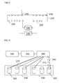
- FIG. 3 shows path information obtained from a storage dump.
- it shows different paths 310 for connecting six different RAID volumes 320 of two different RAID groups 330.
- the information contained in the storage dump does not provide information about the numbers of servers used in the customer environment to access the storage system 200 under analysis, in the second storage system all paths end at a common host group 340.
- the common host group 340 is configured to access all port groups 350 of the second storage system and can therefore access any LUN group 360. It should be noted that these simplifications do not affect the front load balancing shown in Figure 2 .
- the test environment 450 comprises a second storage system 400, a network switch 430 and a server computer 440.
- the network switch 430 is a Fibre Channel switch for implementing a SAN.
- each host port 410 of the network switch 430 is connected to each storage port 420 of the second storage system 400.
- a virtualization system is used.
- the single physical server computer 440 makes use of a hypervisor, such as the virtualization software EXSI 5.0 or above of VMware Inc., Palo Alto, US, to run a number of virtual machines within the server computer 440 of the test environment 450 used for simulating the storage system 200.
- a hypervisor such as the virtualization software EXSI 5.0 or above of VMware Inc., Palo Alto, US
- a single virtual machine is installed in the virtualization system.
- the virtual machine description is provided by the simulation software used for the automatic configuration and/or operation of the testing environment.
- the configuration of the virtual machine to be provided can be altered by the user. Based on the single template virtual machine provided, other virtual machines are cloned automatically.
- FIG. 5 shows a virtual machine 510 for implementing a RAID group 330 comprising three RAID volumes 320.
- one virtual machine 510 is required for each active RAID group 330 of the analyzed storage system 200 of the customer configuration.
- one virtual machine 510 is used to implement each RAID group 330 of the first storage system 200.
- the generated virtual machine 510 is named in an automatic fashion based on the information obtained from the configuration of the first storage system 200. For example, a common prefix followed by a name corresponding to the name of the RAID group 330 in the customer configuration can be used.
- a virtual machine 510 used to implement a RAID group 330 named "RAIDA" of the storage system 200 may be named "VM_RAIDA" in the test environment 450.
- the virtual machine 510 for the RAID group 330 is generated, all volumes 320 contained in said RAID group 330 are mapped to the virtual machine 510.
- the path via which each volume 320 is connected is mapped in accordance with information obtained from the storage dump in order to maintain host affinity.
- the path may follow a round robin approach for load balancing, as detailed in the Technical Note by VMware on "Round-Robin Load Balancing", 2007, Revision 20071119 (available from http://www.vmware.com/pdf/vi3_35_25_roundrobin.pdf). However, this may be changed by the user.
- the above mentioned provisioning and configuration of the virtual machine 510 is provided automatically in the background by the software for configuring the test environment 450.
- FIG. 6 shows the overall architecture 600 of the test environment 450 according to the described embodiment. It comprises a plurality of virtual machines 510 implementing the RAID groups 330 of the first storage system 200. These are executed by the server computer 440 running a hypervisor 610. Through the hypervisor 610, the virtual machines 510 access components of physical RAID systems 620 comprising disks 630 of the storage system 400 of the test environment 450.
- the test environment 450 may comprise more than one server computer 440 (not shown).
- every server computer will comprise a virtual machine 510 for each active RAID group 330 of the first storage system 200 while the I/O load will be spread across the different server computers running the respective virtual machines 510.
- FIGs. 7A and 7B show the data structure of fingerprints used for simulating a workload of the first storage system 200 in the test environment 450.
- time segments or use default time segments used for the simulation For example, a time segment having a length between 30 seconds of up to five minutes may be specified by a user. Based on the specified time segment, the total workload observed for the storage system 200, for example based on log files, is divided into separate chunks. For example, for time segments of five minutes, performance data collected over the course of an hour can be divided into twelve separate chunks. For each chunk and RAID volume 320, a set of fingerprints is generated and later executed by the virtual machines 510.
- a first fingerprint 710 comprises information regarding accesses to a given RAID volume 320. This is shown in FIG. 7A .
- the type of storage access i.e. whether it is a read or write access
- the size of accesses may be analyzed.
- the read IOPS for each segment is calculated by taking an average of all the read IOPS for the time span equal to that of the segment specified by user. The same process is carried out for the write IOPS, read block size and write block size as well.
- the fingerprint 710 may contain information regarding the randomness of the received accesses, i.e. whether they are sequential or random in nature.
- a first fingerprint 710 is generated for each RAID volume 320 specifying the volume name, the percentage of read IOPS, the average size of a read block, the percentage of write IOPS, and the average size of a write block as well as a user specified degree of randomness.
- FIG. 7B shows the data structure of a second fingerprint 720.
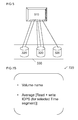
- the second fingerprint 720 comprises the volume name of the RAID volume 320 as well as the average access rate for a selected time segment.
- the second fingerprint 720 shows the total number of read and write IOPS for a given time segment to show the absolute load of the corresponding RAID volume 320 in a given time segment.
- each virtual machine 510 used to operate a particular RAID group 330 processes at least one first fingerprint 710 in real time for each time segment.
- a benchmarking software such as the software described in the paper 479-2013 of the SAS Global Forum 2013 titled "Benchmarking SAS® I/O: Verifying I/O Performance Using fio” by Spencer Hayes is used to generate a workload in accordance with the first fingerprint 710.
- the second fingerprint 720 is used by the hypervisor 610 in order to limit a maximum data flow in accordance with the information stored therein.
- the hypervisor 610 the number of IOPS for each RAID volume 320 for each virtual machine 510 can be set.
- the average IOPS on each RAID volume 320 is calculated and then set as a maximum limit on a corresponding link for each virtual machine 510. This information is processed in real time for each time segment and each virtual machine 510.
- a workload characteristic for the first storage system 200 can be simulated for the second storage system 400.
- the maximum limit is set for each raw device mapping (RDM), corresponding to a symbolic link from a virtual machine file system (VMFS) volume to a raw LUN device.
- RDM raw device mapping
- VMFS virtual machine file system
- a separate software module which provides graphical information for the original workload of the first storage system 200 and the simulated workload in the second storage system 400. This helps in analyzing the similarity between the respective scenarios and storage systems, respectively.
- graphs are generated for all relevant storage components, i.e. RAID groups 330, RAID volumes 320, and port groups based on the names determined from the storage dump. For example, for the RAID groups 330 and volumes 320, IOPS, read and write block sizes, response times and other storage parameters may be plotted. For the port groups, the front load balancing of the storage systems 200 and 400 may be plotted.
- FIGs. 8A and 8B show results of the RAID performance plot for a so-called RAID-5+0 system.
- FIG. 8A shows the workload of the original first storage system 200 comprising twelve disks 230 in a RAID-5+0 configuration.
- FIG. 8A shows the number of IOPS averaged over several subsequent data collection intervals of five minutes each.
- FIG. 8B shows the corresponding simulated workload of a second storage system 400 for the same data collection intervals.
- the general shape and amplitude of the simulated workload patterns correspond quite well with the original workload pattern of FIG. 8A .
- some simplifications applied for example by reducing the number of disks in the second storage system 400 to a total of six disks 630, some minor variations between the simulated workload and the original workload can be observed.
- This and other information provided by the simulated workload of the second storage system 400 can be used to pinpoint bottlenecks in the configuration of the first storage system 200. Furthermore, by modifying the configuration of the second storage system 400, the impact of such configuration changes can be first analyzed, before they are applied to the customer storage system 200.
- the simulation software is capable of reproducing an exact number of read/write input/output operations per second (IOPS) and read/write packet sizes, in a test environment 450 by utilizing a much smaller number of server computers and storage devices as compared to the original storage system 200 and environment to be analyzed.
- the simulation software provides the following functionalities and features:
- Such a software results in a number of advantages, comprising the minimization of hardware requirements, the creation of simulations, potentially with the help of a user-friendly graphical user interface (GUI), which in turn reduces the time and effort needed in system analysis. It also adds flexibility, in case basic requirements for simulating a storage system 200 are not met.
- GUI graphical user interface
Landscapes
- Engineering & Computer Science (AREA)
- Theoretical Computer Science (AREA)
- General Engineering & Computer Science (AREA)
- Physics & Mathematics (AREA)
- General Physics & Mathematics (AREA)
- Human Computer Interaction (AREA)
- Computer Hardware Design (AREA)
- Quality & Reliability (AREA)
- Software Systems (AREA)
- Debugging And Monitoring (AREA)
Abstract
Description
- The present invention relates to a method for simulating a workload of a storage system. Furthermore, the present invention relates to the use of performance data, a computer system for simulating a workload of a storage system, and a computer program product.
- Due to the increase in data to be processed and stored electronically, computer based storage systems have grown ever more complex over the recent years. This trend has recently been accelerated by the widespread use of centralized data management in so called data centers as well as server virtualization. In consequence, storage systems of data centers often comprise a large number of storage devices, such as magnetic or magneto/optical storage drives, non-volatile semiconductor memory devices, magnetic tape storage devices, and others. The individual storage devices are often grouped to form more complex storage subsystems, for example redundant array of independent disks (RAID) systems comprising a large number of storage devices. Such storage subsystems are sometimes further aggregated to form storage systems connected by one or more storage area networks (SAN). For both performance and redundancy reasons, components of such a complex storage system are often replicated at various levels of the storage architecture.
- As the complexity of storage systems grows, the task of optimizing and maintaining the storage systems becomes more complex. For this purpose, storage systems currently available often provide specialized software tools that allow a limited analysis of the operation of the storage system, such as measuring the amount of available storage capacity, measuring an actual data throughput and the like. While such data is useful to monitor the current operating status of a storage system, it is insufficient to analyze a storage system in detail in case an error occurs or in order to optimize the performance of the storage system. Consequently, it is one object of the present invention to provide methods and systems that enhance the capability of analyzing and optimizing of a storage system.
- According to a first aspect of the present invention, a method for simulating a workload of a storage system is disclosed. The method comprises the steps:
- obtaining configuration data regarding first components of the first storage system,
- obtaining performance data, the performance data comprising workload information of the first storage system,
- configuring second components of a second storage system based on the obtained configuration data, and
- operating the second storage system using a simulated workload based on the obtained performance data.
- The method in accordance with the first aspects provides two elements that may help to analyze a storage system. Firstly, rather than operating on the first storage system itself, corresponding components of a second storage system are configured based on configuration data obtained from the first storage system. For example, rather than operating a storage system deployed at a customer site, a storage system of a manufacturer or service company employed in a test environment may be operated. In this way, interference with the actual operation of the first storage system can be avoided. Secondly, rather than using an actual workload which may comprise confidential or otherwise restricted information and may not be easily available at a point of analysis, a simulated workload based on performance data comprising workload information of the first storage system is used to operate the second storage system. In this way, a method for simulating a workload of a storage system can be provided, which is independent of the first storage system and does not require the setup of a storage system identical to the first storage system.
- According to a preferred embodiment, the number of second components of the second storage system is smaller than the number of first components of the first storage system. By way of simulation, the hardware requirements for simulating the workload of a storage system can be reduced. For example, the simulation may be generated by emulating the hardware of the first storage system in such a way that the hardware requirements of the second storage system are minimized.
- In particular, according to one embodiment, only first components of the first storage system having a corresponding workload in excess of predefined thresholds are mapped to a corresponding second component of the simulating storage device. By omitting unused or hardly used components, such as RAID groups not accessed by an application to be simulated, the complexity of the second storage system can be reduced. Alternatively or in addition, the first components comprise a first plurality of ports, the configuration data comprise information about at least one port group and, for each port group, information about a first group of ports of the first plurality of ports associated with the respective port group. The second components comprise a second plurality of ports, wherein the simulating system is configured to create only those port groups comprising at least one port of the second plurality of ports and to associate only those ports of the second plurality of ports with a corresponding port group of the simulating system. For redundancy reasons, storage systems deployed in a data center often comprise so-called port groups that comprise a number of redundant ports. However, in case the second storage system comprises a smaller number of ports, individual ports or entire port groups may be omitted in the system configuration of the second storage system without affecting the operation of the simulating storage device under normal conditions, i.e. without breakdown of a particular component.
- Furthermore, the first components may comprise at least one first RAID group and a first set of storage devices associated with the first RAID group, and the configuration data comprises data indicating a RAID level used by the first RAID group. The second components comprise a corresponding second RAID group and a second set of storage devices associated with the second RAID group, wherein the second set of storage devices consists of a minimum number of storage devices required to simulate a RAID group using the RAID level indicated by the configuration data. As a further simplification, simulated RAID groups may be configured with a minimum number of storage devices required in order to implement a used RAID level of the first storage system. That is, not all storage devices provided in the actual first storage system need to be provided in the second storage system in order to provide an equivalent functionality.
- According to a further embodiment, the information required for configuring the second storage system and operating the second storage system with a simulated workload may comprise obtaining and analyzing a dump file of the first storage system. Such data representative of the configuration of a first storage system is often provided by a control software of a storage system. Based on this information, a semiautomatic or fully automated system for configuring the second storage system may be provided.
- According to a further embodiment, the method further comprises analyzing the obtained performance data of the storage system to generate fingerprint data comprising workload information for a simulated workload. The use of fingerprint data in order to generate a simulated workload has the advantage that the second storage system, can be operated with an equivalent workload, without reproducing the actual data from the first storage system.
- According to a further embodiment, in the step of obtaining configuration data regarding first components, configuration data of at least one physical hardware component of the first storage system is obtained, and, in the step of configuring second components, a corresponding virtual hardware component of a test environment is configured. By the use of virtualization, the hardware requirements of the test environment can be further reduced.
- In particular, the first storage system may comprise a plurality of RAID groups and the test environment may comprise a corresponding number of RAID groups, wherein for each RAID group a virtual machine controlled by a common hypervisor of the test environment is created. In this way, a test environment for the second storage system may be generated in a fast and efficient manner based on a template virtual machine, thus obliterating the need to provide or copy physical application servers generating a workload on the second storage system.
- Preferably, data of the simulated workload in the second storage system follows a path corresponding to a path of data in the first storage system. In this way, the front loading of the second storage system corresponds to the front loading of the first storage system. In other words, the data follows the same storage path as in the environment of the first storage system.
- According to another embodiment, the method further comprises the step of generating a visual representation of the simulated workload and/or a workload of the first storage system. This will help the user to analyze the similarities between the simulated and the original environment.
- According to a second aspect of the present invention, performance data of a first storage system, which comprises a plurality of components for forming at least one RAID group, is used to generate a simulated workload for operating a second storage system including a corresponding RAID group. The simulated workload results in a front loading of the second storage system equivalent to the front loading of the first storage system.
- The use of performance data for generating a simulated workload has the advantage that a second storage system, comprising for example virtual components and/or a reduced number of physical components, having an equivalent configuration to the first storage system, can be operated with an equivalent workload, without reproducing the actual data from the first storage system.
- According to a third aspect of the present invention, a computer system for simulating a workload of a first storage system is disclosed. The computer system comprises at least on hypervisor and a plurality of virtual machines executed by the hypervisor, wherein each virtual machine is configured to operate at least one RAID group of a second storage system corresponding to at least one associated RAID group of a first storage system. Therein the virtual machines are configured based on configuration data obtained from the storage dump of the first storage system, and a simulated workload is created for each virtual machine using fingerprint data generated based on analyzing performance data of the first storage system. The computer system according to the third aspect can be used to execute the fingerprint in accordance with the second aspect and/or to implement the method in accordance with the first aspect.
- The method in accordance with the first aspect may be executed on a computer system by executing instruction code of a computer program product stored on a non-volatile storage medium according to a fourth aspect.
- The methods and systems in accordance with the present invention will be described in more detail with respect to a specific embodiment with reference to the following figures:
- FIG. 1
- shows a flow chart of a method for simulating a workload of a storage system,
- FIG. 2
- shows a load balancing at front end ports of a first storage system,
- FIG. 3
- shows path information obtained from a storage dump of the first storage system,
- FIG. 4
- shows a test environment comprising a second storage system,
- FIG. 5
- show an example of a virtual machine used to implement a RAID group for the second storage system,
- FIG. 6
- shows an architecture of the second storage system,
- FIGs. 7A and 7B
- show a data structure for fingerprints used for simulating a workload,
- FIGs. 8A and 8B
- show performance data of a first storage system and a second storage system.
- Throughout the figures, common reference signs will be used for corresponding components of embodiments of the present invention.
-
FIG. 1 shows a flow chart of a method 100 for simulating a workload of a storage system. The method 100 in accordance withFIG. 1 overall achieves two key targets, the simulation of hardware of a first storage system and a simulation of a workload of the storage system. - Through the simulation of hardware of the storage system, either the minimum hardware required to allow a meaningful simulation of the first storage system or at least a significantly reduced number of hardware components compared with the first storage system can be used for fault analysis or performance evaluation. By this process, a simplification and, if required, mapping of components from the first storage system to components, physical or virtual, of a second storage system is established as detailed below.
- The simulation of a storage system's workload results in the regeneration of a workload scenario or a usage pattern of a customer storage system for performance evaluation without the need to reproduce all the data used by the customer. By generating a simulated workload rather than using the original data, the copying of a considerable amount of data can be avoided. Furthermore, no security concerns often associated with mission critical data, such as confidential business information or private customer information, arise.
- Method 100 starts with
step 105 in which a user of a simulation software provides information regarding the first storage system. For example, the user provides a storage dump of the first storage system as well as performance data obtained from the first storage system. Such information is usually provided in the form of automatically created log files for most storage systems and can be uploaded in a corresponding software tool for simulating the workload. - In the described embodiment, the storage dump provided in
step 105 comprises information regarding the original configuration of the first storage system. In particular, the storage dump comprises information regarding the number of disks in each RAID system of the storage system, the number of volumes in each RAID system as well as a path of a data flow within the storage system. Furthermore, performance data for various components of the storage system is obtained, for example, by a monitoring system of the first storage system. Practically all storage systems come with a special tool which is used for the purpose of performance monitoring. Generally, this is a built-in feature of the system or comes as a part of the default package with the purchase of the storage system. This tool monitors and records performance parameters for all the major components of the storage system whose performance needs to be evaluated. In case of the ETERNUS storage system of the Fujitsu Technology Solutions GmbH, Germany, the tool used to obtain said performance data is referred to as Performance Monitoring Control Command (PMCC). The obtained performance data may comprise data regarding RAID groups, volumes, front ports and other components of the storage system. Optionally, the user may provide further information required or beneficial for a system configuration. Examples of such additional information are network addresses, such as an IP address of a storage system used for simulation of the first storage system and/or IP addresses of servers accessing the second storage system. - In a
subsequent step 110, the storage architecture of the second storage system needed to simulate the workload of the first storage system is determined. For this purpose, the system analyzes the configuration of the storage system as contained in the dump file inputted instep 105. Furthermore, the performance data may be analyzed in order to identify components that are not or barely used in the storage system. - In the described embodiment, information about all working RAID groups are extracted. For the purpose of the simulation, RAID groups with zero input/output operations per second (IOPS) are not considered. Alternatively, a flexible threshold value may be used in order to distinguish between active RAID groups, which are considered and simulated in the second storage system, and inactive RAID groups which are not considered and simulated in the subsequent simulation and whose workload, if any, is not simulated. Furthermore, information about active volumes is analyzed. Similar as the analysis with respect to the RAID groups, if a volume has zero IOPS or a number of IOPS below a given threshold, then the volume is not considered for a subsequent simulation.
- As a result of
step 110, the total number of disks needed as well as the number of controller modules and ports required for simulating a storage system that is essentially equivalent to the first storage system can be determined. - If the test environment comprises a sufficient number of components in order to simulate all hardware components of the first storage system, in a
decision step 115, the method can immediately proceed to step 150, in which the second storage system is configured in an equivalent way to the first storage system. This essentially means that the storage system used in the test environment provides essentially the same storage architecture and no further simplification of the equivalent storage system determined instep 110 is required. - However, in most situations, not all hardware components of a first storage system may be available in a testing environment. In other words, a similar storage architecture is not available for simulation and the decision in
step 115 is answered in the negative. - In the described embodiment, this case is addressed by two main factors. Firstly, the number of disks used in the second storage system can be reduced. Furthermore, the number of controller modules and ports can also be reduced. This is implemented by executing a subsequent optimization
procedure comprising steps 120 to 145 before the system configuration is carried out instep 150. - In particular, in
step 120, a reduced number of storage devices such as disks of the second storage system may be configured compared to the storage devices of the first storage system. The number of disks can be reduced in either one of two ways. By default, a minimum RAID configuration as determined by strict hardware constraints is used. For this purpose, instep 125, for each detected RAID group, a minimum number of disks required to implement a specific RAID level may be used. For example, for a RAID-1 system, the provision of two disks is sufficient. Similarly, for a RAID-5 system, only three disks are required, and for a RAID-6 system, a minimum of four disks are required to implement said RAID group. - Alternatively, in a
step 130, the user may manually specify a RAID configuration for one or more RAID groups. For example, a user may decide to use a number of disks equivalent to the number of disks of the system to be analyzed with respect to a part of a first storage system in detail. Other RAID groups can be created with a minimum configuration as detailed above. - Other storage system components are by default also simulated using a minimum configuration. Thus, in a
subsequent step 135, a configuration of other components of the second storage system may be determined. In the described embodiment, the number of controller modules, ports and port groups may be reduced with respect to the original configuration of the first storage system. For example, if an original port group of the system to be analyzed comprisesports 1, 2, and 5 but the hardware used for simulating the load of the storage system only comprises ports 1, 2 and 3, the corresponding port group of the second storage system will only comprise ports 1 and 2. Similar simplifications may be applied for other logical groupings, such as affinity groups, logical unit number (LUN) groups, etc. - As detailed before with respect to the disks of the RAID groups, this configuration may be performed in a
step 140 automatically, based on a default minimum configuration, and/or may be modified in astep 145 using a graphical user interface of the simulation software in accordance with specific needs of a user. - Once the components of the storage system used for simulation in accordance with the storage architecture analyzed in
step 110 and potentially simplified insteps 120 to 145 are configured instep 150, a number of servers are configured instep 155 that are used for operating the second storage system. The servers configured instep 155 will be used to generate a workload for the second storage system that is essentially equivalent to the workload as experienced by the first storage system. - In the described embodiment, as a result of the automatic configuration of the second storage system, the simulation software automatically generates virtual machines for all active RAID groups of the first storage system. The second storage system thus comprises corresponding RAID groups with the same RAID level as the first storage system. Within the RAID groups, only active volumes are simulated. In effect, the names of RAID groups and volumes are kept the same as in the customer environment, which helps with performing an evaluation of a simulated workload.
- For this purpose, in a
subsequent step 160, fingerprint data is generated. This fingerprint data can be generated automatically, for example based on performance data of the first storage system provided instep 105, or provided manually for testing purposes. For example, fingerprint data putting a specific load on a given part of the second storage system may be provided by a system engineer. - In the described embodiment, the fingerprint data generated in
step 160 is divided into two distinct parts. The first fingerprint comprises an identifier of a storage volume associated with that fingerprint as well as information about rate, size and/or type of accesses to that storage volume. In other words, the first fingerprint characterizes the nature of the storage accesses to a given storage volume. A second part of the fingerprint data comprises an identifier of the respective storage volume as well as information about an average access rate to the storage volume for a predetermined time segment. In other words, the second part of the fingerprint refers to and limits the development of and limits the load of a particular storage volume over time. Together, the first and second part of the fingerprint represent a workload of the first storage system for a given storage volume. If a fingerprint is provided for each active storage volume, an equivalent overall workload of the first storage system can thus be regenerated based on the fingerprint data. - Based on the information contained in the fingerprint data, the system configured in
steps - The following figures show selected aspects of the architecture and components of the first storage system and the corresponding second storage system.
-
FIG. 2 shows a load balancing at front end ports of astorage system 200. Thestorage system 200 may be located at a customer site. Its load is to be simulated using another storage system in a test environment. Thestorage system 200 comprises a plurality offront end ports 210 for connection to a storage area network (SAN). Over the SAN read and write requests are received by the storage system. Thestorage system 200 further comprisesback end ports 220. Through theback end ports 220, thestorage system 200 is connected to a plurality ofdisks 230. In the example ofFIG. 2 , eachdisk 230 is connected by means of two differentback end ports 220 for redundancy and performance reasons. In general,disks 230 or other storage devices may be connected by any number ofback end ports 230 to a storage system. Thus, requests received at thefront ports 210 of thestorage system 200 can be balanced across theback end ports 220 anddisks 230. - For the purpose of the simulation, the paths through which data flows in the
storage system 200 of the customer environment are traced. This trace information provides information regarding the volumes collected to LUNs, port groups, host groups, and host affinity. This information can be tracked using a so-called storage dump of thestorage system 200 of the customer. Based on the information provided in the storage dump, modeling and implementation of whole paths, comprising for example a LUN group, a port or a port group and a host group, in thestorage system 200 can be performed automatically. -
FIG. 3 shows path information obtained from a storage dump. In particular, it showsdifferent paths 310 for connecting sixdifferent RAID volumes 320 of twodifferent RAID groups 330. As the information contained in the storage dump does not provide information about the numbers of servers used in the customer environment to access thestorage system 200 under analysis, in the second storage system all paths end at acommon host group 340. Thecommon host group 340 is configured to access allport groups 350 of the second storage system and can therefore access anyLUN group 360. It should be noted that these simplifications do not affect the front load balancing shown inFigure 2 . - As a result, a special form of zoning is implemented. In particular, a so-called one-to-all zoning is applied in a test environment 450 as detailed in
FIG. 4 . The test environment 450 comprises asecond storage system 400, anetwork switch 430 and aserver computer 440. In the described embodiment, thenetwork switch 430 is a Fibre Channel switch for implementing a SAN. As can be seen inFIG. 4 , eachhost port 410 of thenetwork switch 430 is connected to eachstorage port 420 of thesecond storage system 400. - For the provision of the simulated work load for the
second storage system 400, in the described embodiment, a virtualization system is used. In particular, the singlephysical server computer 440 makes use of a hypervisor, such as the virtualization software EXSI 5.0 or above of VMware Inc., Palo Alto, US, to run a number of virtual machines within theserver computer 440 of the test environment 450 used for simulating thestorage system 200. - For the simplification of the configuration, only a single virtual machine is installed in the virtualization system. The virtual machine description is provided by the simulation software used for the automatic configuration and/or operation of the testing environment. Alternatively, the configuration of the virtual machine to be provided can be altered by the user. Based on the single template virtual machine provided, other virtual machines are cloned automatically.
-
FIG. 5 shows avirtual machine 510 for implementing aRAID group 330 comprising threeRAID volumes 320. In the described implementation, onevirtual machine 510 is required for eachactive RAID group 330 of the analyzedstorage system 200 of the customer configuration. In other words, onevirtual machine 510 is used to implement eachRAID group 330 of thefirst storage system 200. Preferably, the generatedvirtual machine 510 is named in an automatic fashion based on the information obtained from the configuration of thefirst storage system 200. For example, a common prefix followed by a name corresponding to the name of theRAID group 330 in the customer configuration can be used. For example, avirtual machine 510 used to implement aRAID group 330 named "RAIDA" of thestorage system 200 may be named "VM_RAIDA" in the test environment 450. - Once the
virtual machine 510 for theRAID group 330 is generated, allvolumes 320 contained in saidRAID group 330 are mapped to thevirtual machine 510. The path via which eachvolume 320 is connected is mapped in accordance with information obtained from the storage dump in order to maintain host affinity. In VMWare ESX, the path may follow a round robin approach for load balancing, as detailed in the Technical Note by VMware on "Round-Robin Load Balancing", 2007, Revision 20071119 (available from http://www.vmware.com/pdf/vi3_35_25_roundrobin.pdf). However, this may be changed by the user. By default, the above mentioned provisioning and configuration of thevirtual machine 510 is provided automatically in the background by the software for configuring the test environment 450. -
FIG. 6 shows the overall architecture 600 of the test environment 450 according to the described embodiment. It comprises a plurality ofvirtual machines 510 implementing theRAID groups 330 of thefirst storage system 200. These are executed by theserver computer 440 running ahypervisor 610. Through thehypervisor 610, thevirtual machines 510 access components ofphysical RAID systems 620 comprisingdisks 630 of thestorage system 400 of the test environment 450. - In case particularly high workloads are to be simulated, the test environment 450 may comprise more than one server computer 440 (not shown). In this case, every server computer will comprise a
virtual machine 510 for eachactive RAID group 330 of thefirst storage system 200 while the I/O load will be spread across the different server computers running the respectivevirtual machines 510. -
FIGs. 7A and7B show the data structure of fingerprints used for simulating a workload of thefirst storage system 200 in the test environment 450. - In order to generate the respective data structures, the user is asked to specify time segments or use default time segments used for the simulation. For example, a time segment having a length between 30 seconds of up to five minutes may be specified by a user. Based on the specified time segment, the total workload observed for the
storage system 200, for example based on log files, is divided into separate chunks. For example, for time segments of five minutes, performance data collected over the course of an hour can be divided into twelve separate chunks. For each chunk andRAID volume 320, a set of fingerprints is generated and later executed by thevirtual machines 510. - In the described embodiment, two different types of fingerprints are generated. A first fingerprint 710 comprises information regarding accesses to a given
RAID volume 320. This is shown inFIG. 7A . In particular, the type of storage access, i.e. whether it is a read or write access, is recorded for each access. Furthermore, the size of accesses may be analyzed. The read IOPS for each segment is calculated by taking an average of all the read IOPS for the time span equal to that of the segment specified by user. The same process is carried out for the write IOPS, read block size and write block size as well. Furthermore, the fingerprint 710 may contain information regarding the randomness of the received accesses, i.e. whether they are sequential or random in nature. However, in the described embodiment, this information is not obtained automatically but may be specified by the user. As a result, a first fingerprint 710 is generated for eachRAID volume 320 specifying the volume name, the percentage of read IOPS, the average size of a read block, the percentage of write IOPS, and the average size of a write block as well as a user specified degree of randomness. -
FIG. 7B shows the data structure of a second fingerprint 720. The second fingerprint 720 comprises the volume name of theRAID volume 320 as well as the average access rate for a selected time segment. In other words, the second fingerprint 720 shows the total number of read and write IOPS for a given time segment to show the absolute load of the correspondingRAID volume 320 in a given time segment. - During the running of a simulated workload, each
virtual machine 510 used to operate aparticular RAID group 330 processes at least one first fingerprint 710 in real time for each time segment. For this purpose, a benchmarking software, such as the software described in the paper 479-2013 of the SAS Global Forum 2013 titled "Benchmarking SAS® I/O: Verifying I/O Performance Using fio" by Spencer Hayes is used to generate a workload in accordance with the first fingerprint 710. - As benchmarking software by definition tries to obtain the maximum number of reads and writes according to the profile stored in the first fingerprint 710, the second fingerprint 720 is used by the
hypervisor 610 in order to limit a maximum data flow in accordance with the information stored therein. By means of thehypervisor 610, the number of IOPS for eachRAID volume 320 for eachvirtual machine 510 can be set. Based on the second fingerprint 720, the average IOPS on eachRAID volume 320 is calculated and then set as a maximum limit on a corresponding link for eachvirtual machine 510. This information is processed in real time for each time segment and eachvirtual machine 510. Thus, together with the output from the benchmarking software, a workload characteristic for thefirst storage system 200 can be simulated for thesecond storage system 400. - In the described embodiment, the maximum limit is set for each raw device mapping (RDM), corresponding to a symbolic link from a virtual machine file system (VMFS) volume to a raw LUN device. This makes the LUN appear as a physical drive on the virtual machine. In reality, a mapping le is available with the virtual machine, and not the LUN. When a LUN is opened for access, firstly, the mapping le is accessed to obtain the reference information regarding the connected LUN. After that, read and write IO's directly go to a connected LUN instead of going to the mapping file.
- According to an optional feature of the simulation software, a separate software module is provided, which provides graphical information for the original workload of the
first storage system 200 and the simulated workload in thesecond storage system 400. This helps in analyzing the similarity between the respective scenarios and storage systems, respectively. Preferably, graphs are generated for all relevant storage components, i.e.RAID groups 330,RAID volumes 320, and port groups based on the names determined from the storage dump. For example, for theRAID groups 330 andvolumes 320, IOPS, read and write block sizes, response times and other storage parameters may be plotted. For the port groups, the front load balancing of thestorage systems -
FIGs. 8A and 8B show results of the RAID performance plot for a so-called RAID-5+0 system.FIG. 8A shows the workload of the originalfirst storage system 200 comprising twelvedisks 230 in a RAID-5+0 configuration.FIG. 8A shows the number of IOPS averaged over several subsequent data collection intervals of five minutes each. -
FIG. 8B shows the corresponding simulated workload of asecond storage system 400 for the same data collection intervals. As can be seen fromFIG. 8B , the general shape and amplitude of the simulated workload patterns correspond quite well with the original workload pattern ofFIG. 8A . However, due to some simplifications applied, for example by reducing the number of disks in thesecond storage system 400 to a total of sixdisks 630, some minor variations between the simulated workload and the original workload can be observed. - This and other information provided by the simulated workload of the
second storage system 400 can be used to pinpoint bottlenecks in the configuration of thefirst storage system 200. Furthermore, by modifying the configuration of thesecond storage system 400, the impact of such configuration changes can be first analyzed, before they are applied to thecustomer storage system 200. - By means of the detailed embodiment, a simulation software has been described, which makes it possible to simulate the working pattern of a
storage system 200 with the simulation of hardware. In the described embodiment, the simulation software is capable of reproducing an exact number of read/write input/output operations per second (IOPS) and read/write packet sizes, in a test environment 450 by utilizing a much smaller number of server computers and storage devices as compared to theoriginal storage system 200 and environment to be analyzed. According to the described embodiment, the simulation software provides the following functionalities and features: - an understanding of the workload and hardware configuration of a
first storage system 200, - defining a minimum hardware configuration of a
second storage system 400 required in order to recreate a specific workload, - giving specific recommendations to a user of the simulation software, in case the hardware requirements are not currently met,
- front load balancing, i.e. the data in the
second storage system 400 follows the same storage path as in thefirst storage system 200, - automation of hardware configuration including the formation of
RAID groups 330, the cloning ofvirtual machines 510, the mapping ofpaths 310 in accordance with a scenario outlined by a customer betweenvirtual machines 510 and thestorage system 400 and the running of the simulation for a specified amount of time, and - a generation of result graphs which help the user to analyze the similarities between the
second storage system 400 and thefirst storage system 200. - Such a software results in a number of advantages, comprising the minimization of hardware requirements, the creation of simulations, potentially with the help of a user-friendly graphical user interface (GUI), which in turn reduces the time and effort needed in system analysis. It also adds flexibility, in case basic requirements for simulating a
storage system 200 are not met. -
- 100
- method for simulating a workload
- 200
- storage system (to be analyzed)
- 210
- front end port
- 220
- back end port
- 230
- disk (of the storage system 200)
- 310
- path
- 320
- RAID volume
- 330
- RAID group
- 340
- host group
- 350
- port group
- 360
- LUN group
- 400
- (simulating) storage system
- 410
- host port
- 420
- storage port
- 430
- network switch
- 440
- server computer
- 450
- test environment
- 510
- virtual machine
- 600
- architecture
- 610
- hypervisor
- 620
- RAID system (of the storage system 400)
- 630
- disk (of the storage system 400)
- 710
- first fingerprint
- 720
- second fingerprint
Claims (15)
- A method (100) for simulating a workload of a storage system (200) comprising:- obtaining configuration data regarding first components of a first storage system (200);- obtaining performance data comprising workload information of the first storage system (200);- configuring second components of a second storage system (400) based on the obtained configuration data; and- operating the second storage system (400) using a simulated workload based on the obtained performance data.
- The method (100) according to claim 1, wherein the number of second components of the second storage system (400) is smaller than the number of first components of the first storage system (200).
- The method according to claim 2, wherein only first components of the first storage system (200) having a corresponding workload in excess of a predefined threshold are mapped to a corresponding second component of the second storage system (400).
- The method (100) according to claim 2 or 3, wherein the first components comprise a first plurality of ports, the configuration data comprises information about at least one port group (350) and, for each port group (350), information about a first group of ports of the first plurality of ports associated with the respective port group, and the second components of the second storage system (400) comprise a second plurality of ports, wherein the second storage system (400) is configured to create only those port groups (350) comprising at least one port (350) of the second plurality of ports and to associate only ports of the second plurality of ports with a corresponding port group (350) of the second storage system (400).
- The method (100) according to any one of claims 2 to 4, wherein the first components comprise at least one first RAID group (120) and a first set of storage devices associated with the first RAID group (330), the configuration data comprises data indicating a RAID level used by the first RAID group (330), and the second components comprise a corresponding second RAID group (330) and a second set of storage devices associated with the second RAID group (330), wherein the second set of storage devices consists of a minimum number of storage devices required to simulate a RAID group (330) using the RAID level indicated by the configuration data.
- The method (100) according to any one of claims 1 to 5, wherein the step of obtaining configuration data comprises obtaining and analyzing a dump file of the first storage system (200).
- The method (100) according to any one of claims 1 to 6, further comprising analyzing the obtained performance data of the storage system (200) to generate fingerprint data comprising workload information for a simulated workload.
- The method according to claim 7, wherein the fingerprint data comprises, for each storage volume of the first storage system (200), a first fingerprint (710) and/or at least one second fingerprint (720) wherein the first fingerprint (710) comprises an identifier of the storage volume and information about the rate, size and/or type of accesses to the storage volume, in particular a read IOPS, a read block size, a write IOPS and a write block size of the analyzed performance data, and each second fingerprint (720) comprises an identifier of the storage volume and information about an average access rate to the storage volume for a predetermined time segment analyzed, in particular, an average sum of read and write IOPS for the predetermined time segment of analyzed performance data, respectively.
- The method (100) according to claim 1, wherein, in the step of obtaining configuration data regarding first components, configuration data of at least one physical hardware component of the first storage system (200) is obtained, and, in the step of configuring second components, a corresponding virtual hardware components of a test environment (450) is configured.
- The method (100) according claim 9, wherein the first storage system (200) comprises a plurality of RAID groups (330) and the test environment (450) comprises a corresponding number of RAID group (330), wherein for each RAID group a virtual machine (510) controlled by a common hypervisor (610) of the test environment (450) is created, in particular by cloning a virtual machine (510) from a template virtual machine.
- The method (100) according to any one of claims 1 to 10, wherein data of the simulated workload in the second storage system (400) follows a path (310) corresponding to a path of data in the first storage system (200), such that the front loading of the second storage system (400) corresponds to the front loading of the first storage system (200).
- The method (100) according to any one of the claims 1 to 11, further comprising the step of generating a visual representation of the simulated workload of the second storage system (400) and/or a measured workload of the first storage system (200).
- A use of performance data of a first storage system (200), the first storage system (200) comprising a plurality of components for forming at least one RAID group (330), to generate a simulated workload for operating a second storage system (400) including a corresponding RAID group (330) resulting in a front loading of the second storage system (400) equivalent to the front loading of the first storage system (200).
- A computer system for simulating a workload of a first storage system (200), the computer system comprising at least one hypervisor (610) and a plurality of virtual machines (510) executed by the hypervisor (610), wherein each virtual machine (510) is configured to operate at least one RAID group (330) of a second storage system (400) corresponding to at least one associated RAID group (330) of a first storage system (200), wherein the virtual machines (510) are configured based on configuration data obtained from the storage dump of the first storage system (200), and a simulated workload is created for each virtual machine (510) using fingerprint data generated based on analyzing performance data of the first storage system (200).
- A computer program product comprising instruction code for a computer system that, when executed on a computer system, performs the method in accordance with any one of claims 1 to 12.
Priority Applications (2)
| Application Number | Priority Date | Filing Date | Title |
|---|---|---|---|
| EP13182403.9A EP2843537B1 (en) | 2013-08-30 | 2013-08-30 | Method and systems for simulating a workload of a storage system |
| US14/471,704 US10001929B2 (en) | 2013-08-30 | 2014-08-28 | Method and systems for simulating a workload of a storage system |
Applications Claiming Priority (1)
| Application Number | Priority Date | Filing Date | Title |
|---|---|---|---|
| EP13182403.9A EP2843537B1 (en) | 2013-08-30 | 2013-08-30 | Method and systems for simulating a workload of a storage system |
Publications (2)
| Publication Number | Publication Date |
|---|---|
| EP2843537A1 true EP2843537A1 (en) | 2015-03-04 |
| EP2843537B1 EP2843537B1 (en) | 2019-03-27 |
Family
ID=49084823
Family Applications (1)
| Application Number | Title | Priority Date | Filing Date |
|---|---|---|---|
| EP13182403.9A Not-in-force EP2843537B1 (en) | 2013-08-30 | 2013-08-30 | Method and systems for simulating a workload of a storage system |
Country Status (2)
| Country | Link |
|---|---|
| US (1) | US10001929B2 (en) |
| EP (1) | EP2843537B1 (en) |
Cited By (4)
| Publication number | Priority date | Publication date | Assignee | Title |
|---|---|---|---|---|
| WO2017083022A1 (en) * | 2015-11-13 | 2017-05-18 | Google Inc. | Performance monitoring in a distributed storage system |
| CN111949436A (en) * | 2020-08-10 | 2020-11-17 | 星辰天合(北京)数据科技有限公司 | Test data verification method, verification device and computer-readable storage medium |
| US11176017B2 (en) | 2018-12-19 | 2021-11-16 | International Business Machines Corporation | Measurement of simulated mirroring in a data storage system |
| CN116185747A (en) * | 2022-12-09 | 2023-05-30 | 深圳市硅格半导体有限公司 | Storage particle card opening tool debugging method, device and readable storage medium |
Families Citing this family (14)
| Publication number | Priority date | Publication date | Assignee | Title |
|---|---|---|---|---|
| US10001927B1 (en) * | 2014-09-30 | 2018-06-19 | EMC IP Holding Company LLC | Techniques for optimizing I/O operations |
| US9569271B2 (en) * | 2015-02-03 | 2017-02-14 | Dell Products L.P. | Optimization of proprietary workloads |
| US9575811B2 (en) | 2015-02-03 | 2017-02-21 | Dell Products L.P. | Dynamically controlled distributed workload execution |
| US9678798B2 (en) | 2015-02-03 | 2017-06-13 | Dell Products L.P. | Dynamically controlled workload execution |
| US9684540B2 (en) | 2015-02-03 | 2017-06-20 | Dell Products L.P. | Dynamically controlled workload execution by an application |
| US9747121B2 (en) | 2015-04-14 | 2017-08-29 | Dell Products L.P. | Performance optimization of workloads in virtualized information handling systems |
| US10235055B1 (en) * | 2015-12-28 | 2019-03-19 | EMC IP Holding Company LLC | Storage performance testing to evaluate moving data among arrays |
| US10007626B1 (en) * | 2015-12-28 | 2018-06-26 | EMC IP Holding Company | Storage performance testing to evaluate moving data among arrays |
| CN107203442B (en) * | 2016-03-16 | 2020-04-21 | 伊姆西Ip控股有限责任公司 | Method and equipment for evaluating reconstruction performance of redundant array of independent disks |
| US10855532B2 (en) | 2018-10-08 | 2020-12-01 | Dell Products L.P. | System and method to perform solution aware server compliance and configuration |
| US11481117B2 (en) | 2019-06-17 | 2022-10-25 | Hewlett Packard Enterprise Development Lp | Storage volume clustering based on workload fingerprints |
| US11126360B2 (en) * | 2019-10-22 | 2021-09-21 | International Business Machines Corporation | Dynamically adjusting block mode pool sizes |
| US12314581B2 (en) * | 2022-02-09 | 2025-05-27 | Hewlett Packard Enterprise Development Lp | Storage system selection for storage volume deployment |
| US12332773B2 (en) * | 2023-10-13 | 2025-06-17 | Dell Products L.P. | System and method for simulating large capacity configurations in storage systems |
Citations (3)
| Publication number | Priority date | Publication date | Assignee | Title |
|---|---|---|---|---|
| US7392360B1 (en) * | 2002-09-27 | 2008-06-24 | Emc Corporation | Method and system for capacity planning and configuring one or more data storage systems |
| US20120042061A1 (en) * | 2010-08-13 | 2012-02-16 | International Business Machines Corporation | Calibrating cloud computing environments |
| US20120110260A1 (en) * | 2010-10-29 | 2012-05-03 | International Business Machines Corporation | Automated storage provisioning within a clustered computing environment |
Family Cites Families (6)
| Publication number | Priority date | Publication date | Assignee | Title |
|---|---|---|---|---|
| US20060161753A1 (en) * | 2005-01-18 | 2006-07-20 | Aschoff John G | Method, apparatus and program storage device for providing automatic performance optimization of virtualized storage allocation within a virtualized storage subsystem |
| GB0608405D0 (en) * | 2006-04-28 | 2006-06-07 | Ibm | Optimisation of the selection of storage device ports |
| US8880801B1 (en) * | 2011-09-28 | 2014-11-04 | Emc Corporation | Techniques for reliability and availability assessment of data storage configurations |
| US20140130055A1 (en) * | 2012-02-14 | 2014-05-08 | Aloke Guha | Systems and methods for provisioning of storage for virtualized applications |
| JP5958020B2 (en) * | 2012-03-30 | 2016-07-27 | 富士通株式会社 | Storage system |
| US9111232B2 (en) * | 2012-10-31 | 2015-08-18 | Nec Laboratories America, Inc. | Portable workload performance prediction for the cloud |
-
2013
- 2013-08-30 EP EP13182403.9A patent/EP2843537B1/en not_active Not-in-force
-
2014
- 2014-08-28 US US14/471,704 patent/US10001929B2/en not_active Expired - Fee Related
Patent Citations (3)
| Publication number | Priority date | Publication date | Assignee | Title |
|---|---|---|---|---|
| US7392360B1 (en) * | 2002-09-27 | 2008-06-24 | Emc Corporation | Method and system for capacity planning and configuring one or more data storage systems |
| US20120042061A1 (en) * | 2010-08-13 | 2012-02-16 | International Business Machines Corporation | Calibrating cloud computing environments |
| US20120110260A1 (en) * | 2010-10-29 | 2012-05-03 | International Business Machines Corporation | Automated storage provisioning within a clustered computing environment |
Cited By (10)
| Publication number | Priority date | Publication date | Assignee | Title |
|---|---|---|---|---|
| WO2017083022A1 (en) * | 2015-11-13 | 2017-05-18 | Google Inc. | Performance monitoring in a distributed storage system |
| KR20180030168A (en) * | 2015-11-13 | 2018-03-21 | 구글 엘엘씨 | Performance Monitoring of Distributed Storage Systems |
| GB2556772A (en) * | 2015-11-13 | 2018-06-06 | Google Llc | Performance monitoring in a distributed storage system |
| AU2016351383B2 (en) * | 2015-11-13 | 2019-06-06 | Google Llc | Performance monitoring in a distributed storage system |
| US10686686B2 (en) | 2015-11-13 | 2020-06-16 | Google Llc | Performance monitoring in a distributed storage system |
| GB2556772B (en) * | 2015-11-13 | 2021-10-06 | Google Llc | Performance monitoring in a distributed storage system |
| EP3968159A1 (en) * | 2015-11-13 | 2022-03-16 | Google LLC | Performance monitoring in a distributed storage system |
| US11176017B2 (en) | 2018-12-19 | 2021-11-16 | International Business Machines Corporation | Measurement of simulated mirroring in a data storage system |
| CN111949436A (en) * | 2020-08-10 | 2020-11-17 | 星辰天合(北京)数据科技有限公司 | Test data verification method, verification device and computer-readable storage medium |
| CN116185747A (en) * | 2022-12-09 | 2023-05-30 | 深圳市硅格半导体有限公司 | Storage particle card opening tool debugging method, device and readable storage medium |
Also Published As
| Publication number | Publication date |
|---|---|
| US20150066470A1 (en) | 2015-03-05 |
| EP2843537B1 (en) | 2019-03-27 |
| US10001929B2 (en) | 2018-06-19 |
Similar Documents
| Publication | Publication Date | Title |
|---|---|---|
| US10001929B2 (en) | Method and systems for simulating a workload of a storage system | |
| US9798474B2 (en) | Software-defined storage system monitoring tool | |
| US9336340B1 (en) | Evaluating management operations | |
| Wang et al. | A simulation approach to evaluating design decisions in mapreduce setups | |
| JP4235220B2 (en) | Computer system and data migration method | |
| Ahmad | Easy and efficient disk I/O workload characterization in VMware ESX server | |
| US10175973B2 (en) | Microcode upgrade in a storage system | |
| US8468299B2 (en) | Virtualized storage performance controller | |
| US8839026B2 (en) | Automatic disk power-cycle | |
| US20070250302A1 (en) | Simulated storage area network | |
| US10936354B2 (en) | Rebuilding a virtual infrastructure based on user data | |
| US11748241B2 (en) | Method and apparatus for generating simulated test IO operations | |
| CN115373962A (en) | Method, system, storage medium and device for testing IO performance of storage device | |
| US20150012628A1 (en) | Boot acceleration by consolidating client-specific boot data in a data storage system | |
| JP2011013800A (en) | Control part and control method for storage device | |
| US20160036632A1 (en) | Computer system | |
| Méndez et al. | Modeling parallel scientific applications through their input/output phases | |
| JP2008065433A (en) | Computer system and performance tuning method | |
| US20070079060A1 (en) | Method, apparatus and program storage device for providing virtual disk service (VDS) hints based storage | |
| US10789139B2 (en) | Method of rebuilding real world storage environment | |
| CN119088308A (en) | Method and device for determining system parameters, electronic device and storage medium | |
| US10599508B2 (en) | I/O error diagnostics | |
| US20140358479A1 (en) | Storage unit performance adjustment | |
| US11494081B2 (en) | System and method for using telemetry data to change operation of storage middleware client of a data center | |
| US11586527B2 (en) | Automated algorithmic verification in an embedded complex distributed storage environment |
Legal Events
| Date | Code | Title | Description |
|---|---|---|---|
| 17P | Request for examination filed |
Effective date: 20130830 |
|
| AK | Designated contracting states |
Kind code of ref document: A1 Designated state(s): AL AT BE BG CH CY CZ DE DK EE ES FI FR GB GR HR HU IE IS IT LI LT LU LV MC MK MT NL NO PL PT RO RS SE SI SK SM TR |
|
| AX | Request for extension of the european patent |
Extension state: BA ME |
|
| PUAI | Public reference made under article 153(3) epc to a published international application that has entered the european phase |
Free format text: ORIGINAL CODE: 0009012 |
|
| R17P | Request for examination filed (corrected) |
Effective date: 20150714 |
|
| RBV | Designated contracting states (corrected) |
Designated state(s): AL AT BE BG CH CY CZ DE DK EE ES FI FR GB GR HR HU IE IS IT LI LT LU LV MC MK MT NL NO PL PT RO RS SE SI SK SM TR |
|
| 17Q | First examination report despatched |
Effective date: 20160418 |
|
| RAP1 | Party data changed (applicant data changed or rights of an application transferred) |
Owner name: FUJITSU LIMITED |
|
| GRAP | Despatch of communication of intention to grant a patent |
Free format text: ORIGINAL CODE: EPIDOSNIGR1 |
|
| STAA | Information on the status of an ep patent application or granted ep patent |
Free format text: STATUS: GRANT OF PATENT IS INTENDED |
|
| INTG | Intention to grant announced |
Effective date: 20181016 |
|
| GRAS | Grant fee paid |
Free format text: ORIGINAL CODE: EPIDOSNIGR3 |
|
| GRAA | (expected) grant |
Free format text: ORIGINAL CODE: 0009210 |
|
| STAA | Information on the status of an ep patent application or granted ep patent |
Free format text: STATUS: THE PATENT HAS BEEN GRANTED |
|
| AK | Designated contracting states |
Kind code of ref document: B1 Designated state(s): AL AT BE BG CH CY CZ DE DK EE ES FI FR GB GR HR HU IE IS IT LI LT LU LV MC MK MT NL NO PL PT RO RS SE SI SK SM TR |
|
| REG | Reference to a national code |
Ref country code: GB Ref legal event code: FG4D |
|
| REG | Reference to a national code |
Ref country code: CH Ref legal event code: EP |
|
| REG | Reference to a national code |
Ref country code: DE Ref legal event code: R096 Ref document number: 602013052855 Country of ref document: DE |
|
| REG | Reference to a national code |
Ref country code: AT Ref legal event code: REF Ref document number: 1113847 Country of ref document: AT Kind code of ref document: T Effective date: 20190415 |
|
| REG | Reference to a national code |
Ref country code: IE Ref legal event code: FG4D |
|
| PG25 | Lapsed in a contracting state [announced via postgrant information from national office to epo] |
Ref country code: SE Free format text: LAPSE BECAUSE OF FAILURE TO SUBMIT A TRANSLATION OF THE DESCRIPTION OR TO PAY THE FEE WITHIN THE PRESCRIBED TIME-LIMIT Effective date: 20190327 Ref country code: FI Free format text: LAPSE BECAUSE OF FAILURE TO SUBMIT A TRANSLATION OF THE DESCRIPTION OR TO PAY THE FEE WITHIN THE PRESCRIBED TIME-LIMIT Effective date: 20190327 Ref country code: NO Free format text: LAPSE BECAUSE OF FAILURE TO SUBMIT A TRANSLATION OF THE DESCRIPTION OR TO PAY THE FEE WITHIN THE PRESCRIBED TIME-LIMIT Effective date: 20190627 Ref country code: LT Free format text: LAPSE BECAUSE OF FAILURE TO SUBMIT A TRANSLATION OF THE DESCRIPTION OR TO PAY THE FEE WITHIN THE PRESCRIBED TIME-LIMIT Effective date: 20190327 |
|
| REG | Reference to a national code |
Ref country code: NL Ref legal event code: MP Effective date: 20190327 |
|
| PG25 | Lapsed in a contracting state [announced via postgrant information from national office to epo] |
Ref country code: BG Free format text: LAPSE BECAUSE OF FAILURE TO SUBMIT A TRANSLATION OF THE DESCRIPTION OR TO PAY THE FEE WITHIN THE PRESCRIBED TIME-LIMIT Effective date: 20190627 Ref country code: GR Free format text: LAPSE BECAUSE OF FAILURE TO SUBMIT A TRANSLATION OF THE DESCRIPTION OR TO PAY THE FEE WITHIN THE PRESCRIBED TIME-LIMIT Effective date: 20190628 Ref country code: HR Free format text: LAPSE BECAUSE OF FAILURE TO SUBMIT A TRANSLATION OF THE DESCRIPTION OR TO PAY THE FEE WITHIN THE PRESCRIBED TIME-LIMIT Effective date: 20190327 Ref country code: NL Free format text: LAPSE BECAUSE OF FAILURE TO SUBMIT A TRANSLATION OF THE DESCRIPTION OR TO PAY THE FEE WITHIN THE PRESCRIBED TIME-LIMIT Effective date: 20190327 Ref country code: LV Free format text: LAPSE BECAUSE OF FAILURE TO SUBMIT A TRANSLATION OF THE DESCRIPTION OR TO PAY THE FEE WITHIN THE PRESCRIBED TIME-LIMIT Effective date: 20190327 Ref country code: RS Free format text: LAPSE BECAUSE OF FAILURE TO SUBMIT A TRANSLATION OF THE DESCRIPTION OR TO PAY THE FEE WITHIN THE PRESCRIBED TIME-LIMIT Effective date: 20190327 |
|
| REG | Reference to a national code |
Ref country code: AT Ref legal event code: MK05 Ref document number: 1113847 Country of ref document: AT Kind code of ref document: T Effective date: 20190327 |
|
| PG25 | Lapsed in a contracting state [announced via postgrant information from national office to epo] |
Ref country code: CZ Free format text: LAPSE BECAUSE OF FAILURE TO SUBMIT A TRANSLATION OF THE DESCRIPTION OR TO PAY THE FEE WITHIN THE PRESCRIBED TIME-LIMIT Effective date: 20190327 Ref country code: RO Free format text: LAPSE BECAUSE OF FAILURE TO SUBMIT A TRANSLATION OF THE DESCRIPTION OR TO PAY THE FEE WITHIN THE PRESCRIBED TIME-LIMIT Effective date: 20190327 Ref country code: IT Free format text: LAPSE BECAUSE OF FAILURE TO SUBMIT A TRANSLATION OF THE DESCRIPTION OR TO PAY THE FEE WITHIN THE PRESCRIBED TIME-LIMIT Effective date: 20190327 Ref country code: EE Free format text: LAPSE BECAUSE OF FAILURE TO SUBMIT A TRANSLATION OF THE DESCRIPTION OR TO PAY THE FEE WITHIN THE PRESCRIBED TIME-LIMIT Effective date: 20190327 Ref country code: ES Free format text: LAPSE BECAUSE OF FAILURE TO SUBMIT A TRANSLATION OF THE DESCRIPTION OR TO PAY THE FEE WITHIN THE PRESCRIBED TIME-LIMIT Effective date: 20190327 Ref country code: AL Free format text: LAPSE BECAUSE OF FAILURE TO SUBMIT A TRANSLATION OF THE DESCRIPTION OR TO PAY THE FEE WITHIN THE PRESCRIBED TIME-LIMIT Effective date: 20190327 Ref country code: PT Free format text: LAPSE BECAUSE OF FAILURE TO SUBMIT A TRANSLATION OF THE DESCRIPTION OR TO PAY THE FEE WITHIN THE PRESCRIBED TIME-LIMIT Effective date: 20190727 Ref country code: SK Free format text: LAPSE BECAUSE OF FAILURE TO SUBMIT A TRANSLATION OF THE DESCRIPTION OR TO PAY THE FEE WITHIN THE PRESCRIBED TIME-LIMIT Effective date: 20190327 |
|
| PGFP | Annual fee paid to national office [announced via postgrant information from national office to epo] |
Ref country code: DE Payment date: 20190827 Year of fee payment: 7 Ref country code: FR Payment date: 20190822 Year of fee payment: 7 |
|
| PG25 | Lapsed in a contracting state [announced via postgrant information from national office to epo] |
Ref country code: PL Free format text: LAPSE BECAUSE OF FAILURE TO SUBMIT A TRANSLATION OF THE DESCRIPTION OR TO PAY THE FEE WITHIN THE PRESCRIBED TIME-LIMIT Effective date: 20190327 Ref country code: SM Free format text: LAPSE BECAUSE OF FAILURE TO SUBMIT A TRANSLATION OF THE DESCRIPTION OR TO PAY THE FEE WITHIN THE PRESCRIBED TIME-LIMIT Effective date: 20190327 |
|
| PG25 | Lapsed in a contracting state [announced via postgrant information from national office to epo] |
Ref country code: AT Free format text: LAPSE BECAUSE OF FAILURE TO SUBMIT A TRANSLATION OF THE DESCRIPTION OR TO PAY THE FEE WITHIN THE PRESCRIBED TIME-LIMIT Effective date: 20190327 Ref country code: IS Free format text: LAPSE BECAUSE OF FAILURE TO SUBMIT A TRANSLATION OF THE DESCRIPTION OR TO PAY THE FEE WITHIN THE PRESCRIBED TIME-LIMIT Effective date: 20190727 |
|
| PGFP | Annual fee paid to national office [announced via postgrant information from national office to epo] |
Ref country code: GB Payment date: 20190827 Year of fee payment: 7 |
|
| REG | Reference to a national code |
Ref country code: DE Ref legal event code: R097 Ref document number: 602013052855 Country of ref document: DE |
|
| PG25 | Lapsed in a contracting state [announced via postgrant information from national office to epo] |
Ref country code: DK Free format text: LAPSE BECAUSE OF FAILURE TO SUBMIT A TRANSLATION OF THE DESCRIPTION OR TO PAY THE FEE WITHIN THE PRESCRIBED TIME-LIMIT Effective date: 20190327 |
|
| PLBE | No opposition filed within time limit |
Free format text: ORIGINAL CODE: 0009261 |
|
| STAA | Information on the status of an ep patent application or granted ep patent |
Free format text: STATUS: NO OPPOSITION FILED WITHIN TIME LIMIT |
|
| PG25 | Lapsed in a contracting state [announced via postgrant information from national office to epo] |
Ref country code: SI Free format text: LAPSE BECAUSE OF FAILURE TO SUBMIT A TRANSLATION OF THE DESCRIPTION OR TO PAY THE FEE WITHIN THE PRESCRIBED TIME-LIMIT Effective date: 20190327 |
|
| 26N | No opposition filed |
Effective date: 20200103 |
|
| PG25 | Lapsed in a contracting state [announced via postgrant information from national office to epo] |
Ref country code: TR Free format text: LAPSE BECAUSE OF FAILURE TO SUBMIT A TRANSLATION OF THE DESCRIPTION OR TO PAY THE FEE WITHIN THE PRESCRIBED TIME-LIMIT Effective date: 20190327 |
|
| PG25 | Lapsed in a contracting state [announced via postgrant information from national office to epo] |
Ref country code: LI Free format text: LAPSE BECAUSE OF NON-PAYMENT OF DUE FEES Effective date: 20190831 Ref country code: MC Free format text: LAPSE BECAUSE OF FAILURE TO SUBMIT A TRANSLATION OF THE DESCRIPTION OR TO PAY THE FEE WITHIN THE PRESCRIBED TIME-LIMIT Effective date: 20190327 Ref country code: LU Free format text: LAPSE BECAUSE OF NON-PAYMENT OF DUE FEES Effective date: 20190830 Ref country code: CH Free format text: LAPSE BECAUSE OF NON-PAYMENT OF DUE FEES Effective date: 20190831 |
|
| REG | Reference to a national code |
Ref country code: BE Ref legal event code: MM Effective date: 20190831 |
|
| PG25 | Lapsed in a contracting state [announced via postgrant information from national office to epo] |
Ref country code: IE Free format text: LAPSE BECAUSE OF NON-PAYMENT OF DUE FEES Effective date: 20190830 |
|
| PG25 | Lapsed in a contracting state [announced via postgrant information from national office to epo] |
Ref country code: BE Free format text: LAPSE BECAUSE OF NON-PAYMENT OF DUE FEES Effective date: 20190831 |
|
| REG | Reference to a national code |
Ref country code: DE Ref legal event code: R119 Ref document number: 602013052855 Country of ref document: DE |
|
| GBPC | Gb: european patent ceased through non-payment of renewal fee |
Effective date: 20200830 |
|
| PG25 | Lapsed in a contracting state [announced via postgrant information from national office to epo] |
Ref country code: CY Free format text: LAPSE BECAUSE OF FAILURE TO SUBMIT A TRANSLATION OF THE DESCRIPTION OR TO PAY THE FEE WITHIN THE PRESCRIBED TIME-LIMIT Effective date: 20190327 |
|
| PG25 | Lapsed in a contracting state [announced via postgrant information from national office to epo] |
Ref country code: HU Free format text: LAPSE BECAUSE OF FAILURE TO SUBMIT A TRANSLATION OF THE DESCRIPTION OR TO PAY THE FEE WITHIN THE PRESCRIBED TIME-LIMIT; INVALID AB INITIO Effective date: 20130830 Ref country code: MT Free format text: LAPSE BECAUSE OF FAILURE TO SUBMIT A TRANSLATION OF THE DESCRIPTION OR TO PAY THE FEE WITHIN THE PRESCRIBED TIME-LIMIT Effective date: 20190327 Ref country code: DE Free format text: LAPSE BECAUSE OF NON-PAYMENT OF DUE FEES Effective date: 20210302 Ref country code: FR Free format text: LAPSE BECAUSE OF NON-PAYMENT OF DUE FEES Effective date: 20200831 |
|
| PG25 | Lapsed in a contracting state [announced via postgrant information from national office to epo] |
Ref country code: GB Free format text: LAPSE BECAUSE OF NON-PAYMENT OF DUE FEES Effective date: 20200830 |
|
| PG25 | Lapsed in a contracting state [announced via postgrant information from national office to epo] |
Ref country code: MK Free format text: LAPSE BECAUSE OF FAILURE TO SUBMIT A TRANSLATION OF THE DESCRIPTION OR TO PAY THE FEE WITHIN THE PRESCRIBED TIME-LIMIT Effective date: 20190327 |