EP2842888B1 - A container assembly and a lid - Google Patents
A container assembly and a lid Download PDFInfo
- Publication number
- EP2842888B1 EP2842888B1 EP13182600.0A EP13182600A EP2842888B1 EP 2842888 B1 EP2842888 B1 EP 2842888B1 EP 13182600 A EP13182600 A EP 13182600A EP 2842888 B1 EP2842888 B1 EP 2842888B1
- Authority
- EP
- European Patent Office
- Prior art keywords
- lid
- inner bag
- outer box
- container assembly
- central portion
- Prior art date
- Legal status (The legal status is an assumption and is not a legal conclusion. Google has not performed a legal analysis and makes no representation as to the accuracy of the status listed.)
- Not-in-force
Links
Images



Classifications
-
- B—PERFORMING OPERATIONS; TRANSPORTING
- B65—CONVEYING; PACKING; STORING; HANDLING THIN OR FILAMENTARY MATERIAL
- B65D—CONTAINERS FOR STORAGE OR TRANSPORT OF ARTICLES OR MATERIALS, e.g. BAGS, BARRELS, BOTTLES, BOXES, CANS, CARTONS, CRATES, DRUMS, JARS, TANKS, HOPPERS, FORWARDING CONTAINERS; ACCESSORIES, CLOSURES, OR FITTINGS THEREFOR; PACKAGING ELEMENTS; PACKAGES
- B65D88/00—Large containers
- B65D88/16—Large containers flexible
- B65D88/1612—Flexible intermediate bulk containers [FIBC]
- B65D88/1668—Flexible intermediate bulk containers [FIBC] closures for top or bottom openings
-
- B—PERFORMING OPERATIONS; TRANSPORTING
- B65—CONVEYING; PACKING; STORING; HANDLING THIN OR FILAMENTARY MATERIAL
- B65D—CONTAINERS FOR STORAGE OR TRANSPORT OF ARTICLES OR MATERIALS, e.g. BAGS, BARRELS, BOTTLES, BOXES, CANS, CARTONS, CRATES, DRUMS, JARS, TANKS, HOPPERS, FORWARDING CONTAINERS; ACCESSORIES, CLOSURES, OR FITTINGS THEREFOR; PACKAGING ELEMENTS; PACKAGES
- B65D88/00—Large containers
- B65D88/16—Large containers flexible
- B65D88/1612—Flexible intermediate bulk containers [FIBC]
- B65D88/1618—Flexible intermediate bulk containers [FIBC] double-walled or with linings
-
- B—PERFORMING OPERATIONS; TRANSPORTING
- B65—CONVEYING; PACKING; STORING; HANDLING THIN OR FILAMENTARY MATERIAL
- B65D—CONTAINERS FOR STORAGE OR TRANSPORT OF ARTICLES OR MATERIALS, e.g. BAGS, BARRELS, BOTTLES, BOXES, CANS, CARTONS, CRATES, DRUMS, JARS, TANKS, HOPPERS, FORWARDING CONTAINERS; ACCESSORIES, CLOSURES, OR FITTINGS THEREFOR; PACKAGING ELEMENTS; PACKAGES
- B65D88/00—Large containers
- B65D88/16—Large containers flexible
- B65D88/1612—Flexible intermediate bulk containers [FIBC]
- B65D88/1656—Flexible intermediate bulk containers [FIBC] for liquids
Definitions
- the present invention relates to a container assembly, comprising an outer box including a bottom and a circumferential side wall, and an inner bag for containing a liquid.
- Such a container assembly is known in the art and often called a bag-in-box.
- the inner bag or liner may be suitable for containing and conserving a perishable liquid.
- the outer box may create a predefined shape of the container assembly and protect the inner bag against any damaging impact from outside.
- the inner bag When the inner bag is filled with a liquid its walls will be pressed against the bottom and the upright circumferential side wall of the outer box, whereas the upper side of the filled inner bag will form a horizontal surface.
- a disadvantage of the known container assembly is that in a filled condition the liquid at the upper side of the filled inner bag moves back and forth when transported over a bumpy road surface.
- Free motion of the upper portion of a filled inner bag can be reduced by covering the upper side.
- a net or cloth or the like can be stretched over the outer box.
- US5192134 discloses a flexible bulk containers and, more particularly, to a flexible bulk container in the form of a bag made of a woven fabric of a design which container is suitable for the handling and storage of flowable granular or powdered bulk materials which must maintain absolute purity and freedom from contamination.
- US1228652 (Daugherty ) relates to mail bags having a plurality of vertically arranged elongated opening, a closure therefor comprising a cap member, which cap member is formed of flexible material, such as leather, which cap is hinged with respect to the body of the bag.
- WO0198157 (Composite Container) teaches of a flexible intermediate bulk container as used for handling flowable materials in granular or powder form such as chemicals, minerals, fertilizers, foodstuffs, grains and agricultural products, etc.
- US6244443 (BAG Corp) teaches of an octagon-shaped stackable flexible intermediate bulk container and method of manufacture.
- the container assembly according to the invention as claimed in claim 1 which comprises a rigid lid which fits inside the circumferential side wall of the outer box for covering the upper side of the inner bag in a filled condition thereof at least in a circumferential region thereof adjacent to the side wall of the outer box, and a fixation member for keeping the lid on the inner bag in its filled condition, which fixation member is attachable to at least one of the inner bag and the outer box at different vertical locations of the lid with respect to the outer box.
- the rigid lid can contact the upper side of the inner bag in its filled condition and retained thereon independent from the filling level of the inner bag with respect to the outer box.
- the fixation member is adapted such that at each filling level of the inner bag the lid can be placed onto the inner bag and fixed to at least one of the inner bag and the outer box. As a consequence, oscillation of the liquid and the upper side of the inner bag with respect to the outer box can be minimized under rough transport conditions at an arbitrary filling level.
- the fixation member prevents the lid from losing contact with the filled inner bag. It is noted that in practice it is difficult, and often impossible, to fill the inner bag up to the same height level.
- the rigid lid may be slightly flexible, for example when it is made of a relatively thin plastic sheet material, but it is always more rigid than the inner bag.
- the fixation member may press the lid against the upper side of the inner bag firmly so as to further suppress the freedom of oscillation of the liquid.
- outer box may be rigid or semi-rigid.
- the lid has an inner surface to be directed to the inner bag in its filled condition and the inner surface is conical at the circumference of the lid. It is advantageous, since it appears that a smaller vertical force is required for keeping the lid on the inner bag than in the case of a planar inner surface. Besides, a conical inner surface at the circumference of the lid creates an angle between the conical portion and a central portion of the lid as seen in cross section of the lid, which angle is larger than 90° hence minimizing any sharp transition, which might cause damage to the inner bag.
- the fixation member comprises at least two protrusions at opposite sides of the circumference of the lid, which protrusions are fixed to the inner bag and the outer box by means of clamping between the inner bag in its filled condition and the outer box.
- the protrusions are fixed to the lid in at least the assembled condition, on the one hand, and clamped between the inner bag and the outer box, on the other hand, the protrusions are additionally attached to at least one of the inner bag and outer box if the clamping force appears to be insufficient for keeping the lid on the inner bag.
- the locations of the protrusions, i.e. at opposite sides of the circumference of the lid supports the stability of keeping the lid on the filled inner bag.
- the protrusions are part of a tension belt which extends over the upper side of the lid and forms said protrusions between the inner bag in its filled condition and the outer box at opposite sides of the circumferential side wall.
- portions of the tension belt that form the protrusions are clamped between the inner bag and the outer box whereas another portion of the tension belt extends over the lid so as to pull the lid against the inner bag in its filled condition.
- a plurality of protrusion-forming tension belts extend over the lid in different directions.
- the tension belts also extend in different radial directions through a centre line of the lid the paths of the tension belts may have fixed mutual angular distances so as to create an even force distribution on the lid.
- the tension belt extends over the upper side of the lid in radial direction through a centre line of the lid such that the downward force onto the lid is balanced.
- the protrusions are part of a surrounding wall which projects from the circumference of the lid.
- the surrounding wall comprises an infinite number of protrusions as opposite sides of the circumference of the lid.
- the surrounding wall is a rigid tubular wall since this facilitates to place the tubular wall as a unit between the inner bag and the outer box.
- the lid and the surrounding wall are integrated, hence forming a lid comprising a central portion for at least partially covering the upper side of the inner bag in a filled condition thereof and an enveloping wall portion which projects transversely from the central portion.
- the lid and the fixation member are integrated since the enveloping wall portion functions as the fixation member.
- the central portion may be mainly planar having a closed circumferential region whereas the enveloping wall portion projects from its outer edge.
- the conical portion may form a transition between the enveloping wall portion and the central portion, whereas the transition is concave. Such a gradual transition minimizes the risk of any damage to the inner bag at the mentioned transition.
- the tension belts are strapping belts, which extend over the upper side of the lid, and which are attachable to at least one of the inner bag and the outer box.
- This embodiment may be used if the enveloping wall portion provides insufficient downward force to keep the central portion of the lid on the inner bag under rough transport conditions.
- the strapping belts extend between the inner bag in its filled condition and the outer box, such that its functioning is independent from any height difference between the upper side of the filled inner bag and the upper edge of the circumferential side wall of the outer box.
- several strapping belts may be applied which extend over the lid in different directions, such as described hereinbefore in relation to the tension belt.
- a tensioner may be applied in order to increase the belt tension causing a higher pressure of the lid onto the upper surface of the inner bag.
- the lid may be provided with a through-hole for providing access to an inlet of the inner bag. Nevertheless, the lid covers the upper side of the inner bag in a region adjacent to the side wall of the outer box as described hereinbefore. In practice the through-hole may be located at the centre of the central portion.
- the circumferential side wall of the outer box may have a polygonal cross-section. In a particular embodiment its cross-section forms an octagon. This means that the circumferential edge of the matching lid has a corresponding shape.
- the invention is also related to a lid for a container assembly as described hereinbefore.
- the lid comprises a central portion and an enveloping wall portion which projects transversely from the central portion, and the enveloping wall portion and the central portion form a substantially smooth inner surface, which is conical at a transition between the enveloping wall portion and the central portion.
- the inner surface may be textured, but it should be smooth such that the wall of the inner bag is not damaged upon contacting the lid.
- the conical portion may be concave as described hereinbefore.
- the outer surface of the lid extending opposite to the inner surface may be provided with at least a groove for receiving a tension belt or strapping belt, which groove extends in a plane that intersects the lid in radial direction.
- the groove serves to keep the strapping belt in place on the lid.
- the groove may extend in radial direction at the central portion and in longitudinal direction of the enveloping wall portion.
- the enveloping wall portion may have a polygonal outer circumference in order to fit in an outer box that has a matching circumferential side wall.
- Figs. 1-3 show different views of an embodiment of a container assembly 1.
- the container assembly 1 comprises an outer box 2 including a bottom 3 and a circumferential side wall 4.
- the bottom 3 is made of a flexible material such as woven textile of polypropylene or the like, and may be reinforced by a reinforcing plate.
- the circumferential side wall 4 of the outer box 2 has an octagonal shape, but any alternative shape having a polygonal cross-section is conceivable.
- the octagonal shape approaches a drum shape and appears to be advantageous in terms of efficient use of space and robustness.
- the circumferential side wall 4 is attached to the bottom 3 and may be made of the same material, for example a flexible material such as a cloth of plastic and reinforcing plates.
- the outer box 2 may be rigid.
- the side wall 4 may be made of a double layer cloth, which is divided into lodging parts by stitches in which reinforcing plates are inserted.
- the reinforcing plates may comprise corrugated or foamed plastic panels or the like.
- the outer box 2 may be collapsible in order to save space in case of storing or transporting empty outer boxes 2.
- the dimensions of the outer box 2 may be such that an inner volume of 1,000 litres is created, but smaller or larger volumes are conceivable.
- the outer box 2 is semi-rigid since the circumferential side wall 4 may slightly bulge-out when bulk content is present inside the outer box 2, whereas the reinforcing plates in the side wall 4 are pivotally connected to each other.
- the outer box 2 of the container assembly 1 is provided with lifting straps 5.
- the lifting straps 5 are attached to the outer side of the circumferential side wall 4 such that they form four loops 6 above the outer box 2. This allows the container assembly 1 to be taken up by a forklift truck by means of inserting the forks of the forklift truck through the loops 6 and lifting the container assembly 1.
- the lifting straps 5 are stitched to the side wall 4 in V-shapes, leaving the lifting straps 5 free from the side wall 4 at lower ends of the V-shapes so as to form fastening loops 7.
- a support such as a pallet, can be attached easily to the bottom 3, for example by means of a rope which is drawn through the fastening loops 7 and holes in the support.
- the container assembly 1 also comprises a liner or an inner bag 8 for containing a liquid, see Fig. 3 .
- the inner bag 8 may be made of polyethylene or an alternative plastic. Alternatively, the inner bag 8 may comprise multi-layered walls.
- Fig. 3 shows the container assembly 1 in a filled condition of the inner bag 8. In this condition the content of the inner bag 8 presses the walls of the inner bag 8 against the bottom 3 and the side wall 4 of the outer box 2. It is noted that such a container assembly 1 is also called a bag-in-box type container.
- the container assembly 1 may be designed such that it is stackable, i.e. such that another container assembly 1 can be placed thereon.
- the other container assembly 1 may be supported by the side wall 4. This means that the side wall 4 has to withstand buckling due to a downward force of another container assembly onto the side wall 4 as well as to an outward radial force exerted on the side wall 4 by the filled inner bag 8.
- the container assembly 1 is provided with a rigid lid 9.
- the lid 9 may be made of plastic and fits inside the circumferential side wall 4 of the outer box 2.
- Figs. 4-8 show different views of the lid 9 of the embodiment of the container assembly 1 as shown in Figs. 1-3 .
- Fig. 4 shows an upper side or outer side of the lid 9 and
- Fig. 8 shows a lower side or inner side of the lid 9.
- the lid 9 comprises a mainly planar central portion 10 and an enveloping wall portion 11.
- the enveloping wall portion 11 projects transversely from the central portion 10 and diverges slightly in outward direction for manufacturing reasons since it is made by injection moulding.
- the figures show that the enveloping wall portion 11 has an octagonal shape such that it matches with the interior of the circumferential side wall 4 of the outer box 2.
- the lid 9 has an inner surface 12 which is directed to the inner bag 8 in its filled condition as shown in Fig. 3 .
- the inner surface 12 is concave at a transition between the enveloping wall portion 11 and the central portion 10, see Figs. 7 and 8 .
- Such a conical portion at the circumference of the lid 9 requires relatively little downward force to keep the lid on the inner bag 2.
- the inner surface 12 is substantially smooth in order to avoid any damage to the inner bag 8.
- the lid 9 is provided with a through-hole 13 at the centre of the central portion 10.
- the through-hole 13 provides access to an inlet 14 of the inner bag 8, see Fig. 3 .
- the lid 9 does not cover the entire upper side of the inner bag 8, but in any case a circumferential region adjacent to the side wall 4 of the outer box 2.
- the enveloping wall portion 11 functions as a fixation member for keeping the central portion 10 of the lid 9 on the inner bag 8 in its filled condition, since it is clamped between the inner bag 8 and the outer box 2. Since the lid 9 fits inside the circumferential side wall 4 the enveloping wall portion 11 can be clamped below the upper side of the filled inner bag 8 at different vertical locations of the lid with respect to the outer box 2. This means that the central portion 10 of the lid 9 can be held on the inner bag 8 independent from the filling level thereof.
- the thickness of the enveloping wall portion 11 may be smaller than 5 mm in order to facilitate inserting between the filled inner bag 8 and the circumferential wall 4.
- the lower rim of the enveloping wall portion 11 is curved in order to avoid damage to the inner bag.
- the embodiment as described hereinbefore may also be provided with strapping belts 15 that extend over the outer side of the lid 9. This is shown in Fig. 9 .
- the strapping belts 15 are attached to the inner side of the circumferential side wall 4 in this case, but they may also be attached to the bottom 3 or even to the inner bag 8. Alternatively, the strapping belts 15 are only clamped between the inner bag 8 in filled condition and the circumferential side wall 4.
- the strapping belts 15 function as an additional pressing member or fixation member for pressing the lid 9 on the inner bag 8 in its filled condition.
- its outer side is provided with grooves 16. Figs.
- each of the grooves 16 extends radially from the surrounding edge of the through-hole 13 at the central portion 10 and in longitudinal direction of the enveloping wall portion 11 substantially parallel to a centre line of the lid 9.
- the grooves 16 extend at substantially flat regions of the octagonal enveloping wall portion 11 between neighbouring angles thereof. Since the strapping belts 15 extend between the inner bag 8 and the side wall 4 the distance between the upper edge of the side wall 4 and the upper side of the lid 9 does not influence the paths of the strapping belts 15 over the lid 9.
- the lid 9 may be manufactured by means of injection moulding.
- the inner side of the lid 9 is provided with ridges at locations where the outer surface is provided with the grooves 16.
- the inner surface may be entirely smooth.
- the lid may lack an enveloping wall portion.
- the lid may have a substantially planar central portion, and possibly a conical portion at the circumference thereof. Due to the absence of the enveloping wall portion an alternative fixation member must be present to keep the lid on the inner bag.
- tension belts may be applied over the lid and clamped between the inner bag and the outer box. This means that the tension belts can be attached at different vertical locations of the lid with respect to the outer box. Additionally, the tension belts may be fixed separately to the inner bag and/or the outer box.
- the side wall of the outer box may be configured differently than described hereinbefore.
- the side wall may be provided with reinforcement plates, wherein two adjacent reinforcement plates are made of a single panel that is bent along a bend axis.
- the bent panels are connected to a flexible material, for example a cloth of plastic, such that they are pivotally connected to each other.
- Such an outer box is independent from the inner bag or the lid as described hereinbefore.
- an aspect of the invention is related to a collapsible outer box for receiving a liner, which comprises a circumferential side wall of adjacent segments that are mutually angled so as to form a polygonal cross-section, wherein each two adjacent segments comprise a single reinforcement plate that is bent along a bent axis, and wherein the reinforcement plates are connected to a flexible material such that they are pivotally connected to each other.
- a liner which comprises a circumferential side wall of adjacent segments that are mutually angled so as to form a polygonal cross-section, wherein each two adjacent segments comprise a single reinforcement plate that is bent along a bent axis, and wherein the reinforcement plates are connected to a flexible material such that they are pivotally connected to each other.
- the invention provides an improved container assembly which minimizes the risk of damage to the inner bag during transport under rough conditions.
Landscapes
- Engineering & Computer Science (AREA)
- Mechanical Engineering (AREA)
- Packages (AREA)
Description
- The present invention relates to a container assembly, comprising an outer box including a bottom and a circumferential side wall, and an inner bag for containing a liquid.
- Such a container assembly is known in the art and often called a bag-in-box. The inner bag or liner may be suitable for containing and conserving a perishable liquid. The outer box may create a predefined shape of the container assembly and protect the inner bag against any damaging impact from outside. When the inner bag is filled with a liquid its walls will be pressed against the bottom and the upright circumferential side wall of the outer box, whereas the upper side of the filled inner bag will form a horizontal surface. A disadvantage of the known container assembly is that in a filled condition the liquid at the upper side of the filled inner bag moves back and forth when transported over a bumpy road surface. As a consequence, a transition region of the inner bag that extends between an inner bag portion that is pressed against the side wall of the outer box and the upper portion of the filled inner bag vibrates together with the liquid. Under severe conditions this leads to minor damages at the transition region of the inner bag, known as flex crack failure, allowing air into the inner bag and possibly causing contamination of the liquid.
- Free motion of the upper portion of a filled inner bag can be reduced by covering the upper side. For example, in case of an inner bag which is filled such that its upper side is flush with the upper edge of the outer box, a net or cloth or the like can be stretched over the outer box.
-
US5192134 (Polett ) discloses a flexible bulk containers and, more particularly, to a flexible bulk container in the form of a bag made of a woven fabric of a design which container is suitable for the handling and storage of flowable granular or powdered bulk materials which must maintain absolute purity and freedom from contamination.US1228652 (Daugherty ) relates to mail bags having a plurality of vertically arranged elongated opening, a closure therefor comprising a cap member, which cap member is formed of flexible material, such as leather, which cap is hinged with respect to the body of the bag.WO0198157 US6244443 (BAG Corp) teaches of an octagon-shaped stackable flexible intermediate bulk container and method of manufacture. - It is an object of the present invention to provide an improved container assembly.
- This is achieved by the container assembly according to the invention as claimed in
claim 1, which comprises a rigid lid which fits inside the circumferential side wall of the outer box for covering the upper side of the inner bag in a filled condition thereof at least in a circumferential region thereof adjacent to the side wall of the outer box, and a fixation member for keeping the lid on the inner bag in its filled condition, which fixation member is attachable to at least one of the inner bag and the outer box at different vertical locations of the lid with respect to the outer box. - Due to this feature the rigid lid can contact the upper side of the inner bag in its filled condition and retained thereon independent from the filling level of the inner bag with respect to the outer box. In other words, the fixation member is adapted such that at each filling level of the inner bag the lid can be placed onto the inner bag and fixed to at least one of the inner bag and the outer box. As a consequence, oscillation of the liquid and the upper side of the inner bag with respect to the outer box can be minimized under rough transport conditions at an arbitrary filling level. The fixation member prevents the lid from losing contact with the filled inner bag. It is noted that in practice it is difficult, and often impossible, to fill the inner bag up to the same height level. The rigid lid may be slightly flexible, for example when it is made of a relatively thin plastic sheet material, but it is always more rigid than the inner bag. The fixation member may press the lid against the upper side of the inner bag firmly so as to further suppress the freedom of oscillation of the liquid.
- It is noted that the outer box may be rigid or semi-rigid.
- The lid has an inner surface to be directed to the inner bag in its filled condition and the inner surface is conical at the circumference of the lid. It is advantageous, since it appears that a smaller vertical force is required for keeping the lid on the inner bag than in the case of a planar inner surface. Besides, a conical inner surface at the circumference of the lid creates an angle between the conical portion and a central portion of the lid as seen in cross section of the lid, which angle is larger than 90° hence minimizing any sharp transition, which might cause damage to the inner bag.
- The fixation member comprises at least two protrusions at opposite sides of the circumference of the lid, which protrusions are fixed to the inner bag and the outer box by means of clamping between the inner bag in its filled condition and the outer box. Although the protrusions are fixed to the lid in at least the assembled condition, on the one hand, and clamped between the inner bag and the outer box, on the other hand, the protrusions are additionally attached to at least one of the inner bag and outer box if the clamping force appears to be insufficient for keeping the lid on the inner bag. The locations of the protrusions, i.e. at opposite sides of the circumference of the lid, supports the stability of keeping the lid on the filled inner bag.
- According to the invention, the protrusions are part of a tension belt which extends over the upper side of the lid and forms said protrusions between the inner bag in its filled condition and the outer box at opposite sides of the circumferential side wall. In this case portions of the tension belt that form the protrusions are clamped between the inner bag and the outer box whereas another portion of the tension belt extends over the lid so as to pull the lid against the inner bag in its filled condition.
- A plurality of protrusion-forming tension belts extend over the lid in different directions. In case the tension belts also extend in different radial directions through a centre line of the lid the paths of the tension belts may have fixed mutual angular distances so as to create an even force distribution on the lid.
- Preferably, the tension belt extends over the upper side of the lid in radial direction through a centre line of the lid such that the downward force onto the lid is balanced.
- In an alternative embodiment the protrusions are part of a surrounding wall which projects from the circumference of the lid. In fact the surrounding wall comprises an infinite number of protrusions as opposite sides of the circumference of the lid.
- Preferably, the surrounding wall is a rigid tubular wall since this facilitates to place the tubular wall as a unit between the inner bag and the outer box.
- In an advantageous embodiment the lid and the surrounding wall are integrated, hence forming a lid comprising a central portion for at least partially covering the upper side of the inner bag in a filled condition thereof and an enveloping wall portion which projects transversely from the central portion. This means that the lid and the fixation member are integrated since the enveloping wall portion functions as the fixation member. In practice the central portion may be mainly planar having a closed circumferential region whereas the enveloping wall portion projects from its outer edge.
- In case that the inner surface comprises a conical portion, as described hereinbefore, the conical portion may form a transition between the enveloping wall portion and the central portion, whereas the transition is concave. Such a gradual transition minimizes the risk of any damage to the inner bag at the mentioned transition.
- In addition to the enveloping wall portion that functions as the fixation member, the tension belts are strapping belts, which extend over the upper side of the lid, and which are attachable to at least one of the inner bag and the outer box. This embodiment may be used if the enveloping wall portion provides insufficient downward force to keep the central portion of the lid on the inner bag under rough transport conditions. Preferably, the strapping belts extend between the inner bag in its filled condition and the outer box, such that its functioning is independent from any height difference between the upper side of the filled inner bag and the upper edge of the circumferential side wall of the outer box. In practice several strapping belts may be applied which extend over the lid in different directions, such as described hereinbefore in relation to the tension belt.
- It is noted, that in case of strapping belts / tension belts a tensioner may be applied in order to increase the belt tension causing a higher pressure of the lid onto the upper surface of the inner bag.
- The lid may be provided with a through-hole for providing access to an inlet of the inner bag. Nevertheless, the lid covers the upper side of the inner bag in a region adjacent to the side wall of the outer box as described hereinbefore. In practice the through-hole may be located at the centre of the central portion.
- The circumferential side wall of the outer box may have a polygonal cross-section. In a particular embodiment its cross-section forms an octagon. This means that the circumferential edge of the matching lid has a corresponding shape.
- The invention is also related to a lid for a container assembly as described hereinbefore. The lid comprises a central portion and an enveloping wall portion which projects transversely from the central portion, and the enveloping wall portion and the central portion form a substantially smooth inner surface, which is conical at a transition between the enveloping wall portion and the central portion. The inner surface may be textured, but it should be smooth such that the wall of the inner bag is not damaged upon contacting the lid. The conical portion may be concave as described hereinbefore.
- The outer surface of the lid extending opposite to the inner surface may be provided with at least a groove for receiving a tension belt or strapping belt, which groove extends in a plane that intersects the lid in radial direction. The groove serves to keep the strapping belt in place on the lid. The groove may extend in radial direction at the central portion and in longitudinal direction of the enveloping wall portion. The enveloping wall portion may have a polygonal outer circumference in order to fit in an outer box that has a matching circumferential side wall.
- The invention will hereafter be elucidated with reference to the schematic drawings showing embodiments of the invention by way of example.
-
Fig. 1 is a perspective view of an embodiment of a container assembly according to the invention. -
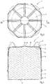
Fig. 2 is a top view of the container assembly as shown inFig. 1 . -
Fig. 3 is a sectional view of the container assembly along the line III-III inFig. 2 . -
Fig. 4 is a perspective view of an embodiment of a lid for a container assembly according to the invention, showing the outer side of the lid. -
Fig. 5 is a side view of the lid as shown inFig. 4 . -
Fig. 6 is a top view of the lid as shown inFig. 4 . -
Fig. 7 is a sectional view of the lid along the line VII-VII inFig. 6 . -
Fig. 8 is a similar view asFig. 4 , but showing the inner side of the lid. -
Fig. 9 is a similar view asFig. 1 , but showing the container assembly including strapping belts. -
Figs. 1-3 show different views of an embodiment of acontainer assembly 1. Thecontainer assembly 1 comprises anouter box 2 including abottom 3 and acircumferential side wall 4. Thebottom 3 is made of a flexible material such as woven textile of polypropylene or the like, and may be reinforced by a reinforcing plate. Thecircumferential side wall 4 of theouter box 2 has an octagonal shape, but any alternative shape having a polygonal cross-section is conceivable. The octagonal shape approaches a drum shape and appears to be advantageous in terms of efficient use of space and robustness. Thecircumferential side wall 4 is attached to thebottom 3 and may be made of the same material, for example a flexible material such as a cloth of plastic and reinforcing plates. Alternatively, theouter box 2 may be rigid. - The
side wall 4 may be made of a double layer cloth, which is divided into lodging parts by stitches in which reinforcing plates are inserted. The reinforcing plates may comprise corrugated or foamed plastic panels or the like. Theouter box 2 may be collapsible in order to save space in case of storing or transporting emptyouter boxes 2. The dimensions of theouter box 2 may be such that an inner volume of 1,000 litres is created, but smaller or larger volumes are conceivable. In the embodiment as shown inFig. 1 theouter box 2 is semi-rigid since thecircumferential side wall 4 may slightly bulge-out when bulk content is present inside theouter box 2, whereas the reinforcing plates in theside wall 4 are pivotally connected to each other. - The
outer box 2 of thecontainer assembly 1 is provided with lifting straps 5. The lifting straps 5 are attached to the outer side of thecircumferential side wall 4 such that they form fourloops 6 above theouter box 2. This allows thecontainer assembly 1 to be taken up by a forklift truck by means of inserting the forks of the forklift truck through theloops 6 and lifting thecontainer assembly 1. The lifting straps 5 are stitched to theside wall 4 in V-shapes, leaving the lifting straps 5 free from theside wall 4 at lower ends of the V-shapes so as to formfastening loops 7. Due to the presence of thefastening loops 7 at theside wall 4 of the outer box 2 a support, such as a pallet, can be attached easily to thebottom 3, for example by means of a rope which is drawn through thefastening loops 7 and holes in the support. - The
container assembly 1 also comprises a liner or aninner bag 8 for containing a liquid, seeFig. 3 . Theinner bag 8 may be made of polyethylene or an alternative plastic. Alternatively, theinner bag 8 may comprise multi-layered walls.Fig. 3 shows thecontainer assembly 1 in a filled condition of theinner bag 8. In this condition the content of theinner bag 8 presses the walls of theinner bag 8 against thebottom 3 and theside wall 4 of theouter box 2. It is noted that such acontainer assembly 1 is also called a bag-in-box type container. - The
container assembly 1 may be designed such that it is stackable, i.e. such that anothercontainer assembly 1 can be placed thereon. Theother container assembly 1 may be supported by theside wall 4. This means that theside wall 4 has to withstand buckling due to a downward force of another container assembly onto theside wall 4 as well as to an outward radial force exerted on theside wall 4 by the filledinner bag 8. - The
container assembly 1 is provided with arigid lid 9. Thelid 9 may be made of plastic and fits inside thecircumferential side wall 4 of theouter box 2.Figs. 4-8 show different views of thelid 9 of the embodiment of thecontainer assembly 1 as shown inFigs. 1-3 .Fig. 4 shows an upper side or outer side of thelid 9 andFig. 8 shows a lower side or inner side of thelid 9. Thelid 9 comprises a mainly planarcentral portion 10 and anenveloping wall portion 11. The envelopingwall portion 11 projects transversely from thecentral portion 10 and diverges slightly in outward direction for manufacturing reasons since it is made by injection moulding. The figures show that the envelopingwall portion 11 has an octagonal shape such that it matches with the interior of thecircumferential side wall 4 of theouter box 2. - In case of a filled
inner bag 8 as shown inFig. 3 thecentral portion 10 contacts the upper side of theinner bag 8, whereas the envelopingwall portion 11 surrounds theinner bag 8 at an upper portion thereof. Due to the rigid character of thelid 9 the upper side of theinner bag 8 at a region adjacent to thecircumferential side wall 4 is protected against free motion during handling of thecontainer assembly 1, for example in severe transport circumstances. - The
lid 9 has aninner surface 12 which is directed to theinner bag 8 in its filled condition as shown inFig. 3 . Theinner surface 12 is concave at a transition between the envelopingwall portion 11 and thecentral portion 10, seeFigs. 7 and 8 . Such a conical portion at the circumference of thelid 9 requires relatively little downward force to keep the lid on theinner bag 2. Furthermore, theinner surface 12 is substantially smooth in order to avoid any damage to theinner bag 8. - In the embodiment as described hereinbefore the
lid 9 is provided with a through-hole 13 at the centre of thecentral portion 10. The through-hole 13 provides access to aninlet 14 of theinner bag 8, seeFig. 3 . This means that in this case thelid 9 does not cover the entire upper side of theinner bag 8, but in any case a circumferential region adjacent to theside wall 4 of theouter box 2. - The enveloping
wall portion 11 functions as a fixation member for keeping thecentral portion 10 of thelid 9 on theinner bag 8 in its filled condition, since it is clamped between theinner bag 8 and theouter box 2. Since thelid 9 fits inside thecircumferential side wall 4 theenveloping wall portion 11 can be clamped below the upper side of the filledinner bag 8 at different vertical locations of the lid with respect to theouter box 2. This means that thecentral portion 10 of thelid 9 can be held on theinner bag 8 independent from the filling level thereof. The thickness of the envelopingwall portion 11 may be smaller than 5 mm in order to facilitate inserting between the filledinner bag 8 and thecircumferential wall 4. Preferably, the lower rim of the envelopingwall portion 11 is curved in order to avoid damage to the inner bag. - The embodiment as described hereinbefore may also be provided with strapping
belts 15 that extend over the outer side of thelid 9. This is shown inFig. 9 . The strappingbelts 15 are attached to the inner side of thecircumferential side wall 4 in this case, but they may also be attached to the bottom 3 or even to theinner bag 8. Alternatively, the strappingbelts 15 are only clamped between theinner bag 8 in filled condition and thecircumferential side wall 4. The strappingbelts 15 function as an additional pressing member or fixation member for pressing thelid 9 on theinner bag 8 in its filled condition. In order to guide the strappingbelts 15 over thelid 9, its outer side is provided withgrooves 16.Figs. 4-8 show that each of thegrooves 16 extends radially from the surrounding edge of the through-hole 13 at thecentral portion 10 and in longitudinal direction of the envelopingwall portion 11 substantially parallel to a centre line of thelid 9. Thegrooves 16 extend at substantially flat regions of the octagonalenveloping wall portion 11 between neighbouring angles thereof. Since the strappingbelts 15 extend between theinner bag 8 and theside wall 4 the distance between the upper edge of theside wall 4 and the upper side of thelid 9 does not influence the paths of the strappingbelts 15 over thelid 9. - The
lid 9 may be manufactured by means of injection moulding. In the embodiment as shown in the figures the inner side of thelid 9 is provided with ridges at locations where the outer surface is provided with thegrooves 16. Alternatively, the inner surface may be entirely smooth. - In an alternative embodiment (not shown) the lid may lack an enveloping wall portion. In such a case, the lid may have a substantially planar central portion, and possibly a conical portion at the circumference thereof. Due to the absence of the enveloping wall portion an alternative fixation member must be present to keep the lid on the inner bag. Similar to the embodiment as described hereinbefore, tension belts may be applied over the lid and clamped between the inner bag and the outer box. This means that the tension belts can be attached at different vertical locations of the lid with respect to the outer box. Additionally, the tension belts may be fixed separately to the inner bag and/or the outer box.
- It is noted that the side wall of the outer box may be configured differently than described hereinbefore. The side wall may be provided with reinforcement plates, wherein two adjacent reinforcement plates are made of a single panel that is bent along a bend axis. Thus, in case of an octagonal side wall four of such bent panels are applied. The bent panels are connected to a flexible material, for example a cloth of plastic, such that they are pivotally connected to each other. Such an outer box is independent from the inner bag or the lid as described hereinbefore. More generally, an aspect of the invention is related to a collapsible outer box for receiving a liner, which comprises a circumferential side wall of adjacent segments that are mutually angled so as to form a polygonal cross-section, wherein each two adjacent segments comprise a single reinforcement plate that is bent along a bent axis, and wherein the reinforcement plates are connected to a flexible material such that they are pivotally connected to each other. It appears that this configuration provides a robust semi-rigid outer box with limited susceptibility to bulging-out. In practice the single plate can be made by means of extrusion, wherein the bent axis extends parallel to the manufacturing direction of the extruded plate.
- From the foregoing, it will be clear that the invention provides an improved container assembly which minimizes the risk of damage to the inner bag during transport under rough conditions.
- The invention is not limited to the embodiments shown in the drawings and described hereinbefore, which may be varied in different manners within the scope of the claims and their technical equivalents.
Claims (11)
- A container assembly (1), comprising an outer box (2) including a bottom (3) and a circumferential side wall (4), and an inner bag (8), a lid (9) which fits inside the circumferential side wall (4) of the outer box (2) for covering the upper side of the inner bag (8) in a filled condition thereof at least in a circumferential region thereof adjacent to the side wall (4) of the outer box (2), and a fixation member for keeping the lid (9) on the inner bag (8) in its filled condition, which fixation member is attachable to at least one of the inner bag (8) and the outer box (2) at different vertical locations of the lid (9) with respect to the outer box (2); characterised in that the lid (9) is rigid and that the inner bag (8) is operable to contain a liquid, wherein the lid (9) has an inner surface to be directed to the inner bag (8) in its filled condition, wherein the inner surface is conical at the circumference of the lid (9);
wherein the fixation member comprises at least two protrusions at opposite sides of the circumference of the lid (9), which protrusions are fixed to the inner bag (8) and the outer box (2) by means of clamping between the inner bag (8) in its filled condition and the outer box (2);
wherein the protrusions are part of a tension belt which extends over the upper side of the lid (9) and forms said protrusions between the inner bag (8) in its filled condition and the outer box (2) at opposite sides of the circumferential side wall (4); and,
wherein a plurality of protrusions-forming tension belts extend over the lid (9) in different directions. - A container assembly (1) according to claim 1, wherein the tension belts extend over the upper side of the lid (9), in a radial direction through a centre line of the lid (9).
- A container assembly (1) according to claim 1 or 2, wherein the protrusions are part of a surrounding wall (11), which projects from the circumference of the lid (9).
- A container assembly (1) according to claim 3, wherein the surrounding wall is a rigid tubular wall (11).
- A container assembly (1) according to claim 4, wherein the lid and the surrounding wall are integrated, hence forming a lid (9) comprising a central portion (10) for at least partially covering the upper side of the inner bag (8) in a filled condition thereof and an enveloping wall portion (11) which projects transversely from the central portion (10).
- A container assembly (1) according to claims 1 or 5, wherein the conical portion forms a transition between the enveloping wall portion (11) and the central portion (10), which transition is concave.
- A container assembly (1) according to one of the claims 1-6, wherein the tension belts are strapping belts (15) which extend over the upper side of the lid (9) and which are attachable to at least one of the inner bag (8) and the outer box (2), which strapping belts (15) preferably extend between the inner bag (8) in its filled condition and the outer box (2).
- A container assembly (1) according to one of the preceding claims, wherein the lid (9) is provided with a through-hole (13) for providing access to an inlet (14) of the inner bag (8).
- A container assembly (1) according to one of the preceding claims, wherein the circumferential side wall (4) of the outer box (2) has a polygonal cross-section, preferably forming an octagon.
- A rigid lid (9) for a container assembly (1) according to one of the preceding claims, which comprises a central portion (10) and an enveloping wall portion (11) which projects transversely from the central portion (10), wherein the enveloping wall portion (11) and the central portion (10) form a substantially smooth inner surface (12), which is conical at a transition between the enveloping wall portion (11) and the central portion (10).
- A rigid lid (9) according to claim 10, wherein an outer surface extending opposite to the inner surface (12) is provided with at least a groove (16) for receiving a strapping belt (15), which groove extends in a plane that intersects the lid (9) in radial direction.
Priority Applications (1)
| Application Number | Priority Date | Filing Date | Title |
|---|---|---|---|
| EP13182600.0A EP2842888B1 (en) | 2013-09-02 | 2013-09-02 | A container assembly and a lid |
Applications Claiming Priority (1)
| Application Number | Priority Date | Filing Date | Title |
|---|---|---|---|
| EP13182600.0A EP2842888B1 (en) | 2013-09-02 | 2013-09-02 | A container assembly and a lid |
Publications (2)
| Publication Number | Publication Date |
|---|---|
| EP2842888A1 EP2842888A1 (en) | 2015-03-04 |
| EP2842888B1 true EP2842888B1 (en) | 2018-05-02 |
Family
ID=49118315
Family Applications (1)
| Application Number | Title | Priority Date | Filing Date |
|---|---|---|---|
| EP13182600.0A Not-in-force EP2842888B1 (en) | 2013-09-02 | 2013-09-02 | A container assembly and a lid |
Country Status (1)
| Country | Link |
|---|---|
| EP (1) | EP2842888B1 (en) |
Family Cites Families (4)
| Publication number | Priority date | Publication date | Assignee | Title |
|---|---|---|---|---|
| US1228652A (en) * | 1916-07-07 | 1917-06-05 | Charles L Daugherty | Mail-bag closure. |
| US5192134A (en) * | 1991-11-12 | 1993-03-09 | Polett Walter J | Re-usable flexible bulk containers |
| US6244443B1 (en) * | 1999-09-03 | 2001-06-12 | B.A.G. Corporation | Octagon shaped stackable flexible intermediate bulk container and method of manufacture |
| WO2001098157A1 (en) * | 2000-06-21 | 2001-12-27 | Composite Container Corp L L C | Composite container for liquids |
-
2013
- 2013-09-02 EP EP13182600.0A patent/EP2842888B1/en not_active Not-in-force
Non-Patent Citations (1)
| Title |
|---|
| None * |
Also Published As
| Publication number | Publication date |
|---|---|
| EP2842888A1 (en) | 2015-03-04 |
Similar Documents
| Publication | Publication Date | Title |
|---|---|---|
| US8424682B2 (en) | Transport and storage container | |
| US9751691B2 (en) | Silosack container | |
| US7506776B2 (en) | Braceless liner | |
| US8690048B2 (en) | Reinforced container system | |
| US8678652B1 (en) | Stackable, flexible, intermediate bulk bag container having corner baffles | |
| EP2785616B1 (en) | Container system comprising a "big bag", a support and a rope | |
| WO1997028049A2 (en) | Flexible bulk container with supporting side beams | |
| KR200454330Y1 (en) | Container bag | |
| KR102296082B1 (en) | Baffle bag | |
| US20110315689A1 (en) | Bulk Packaging Container | |
| US20040184679A1 (en) | Bulk bag for meat and meat products | |
| US6287003B1 (en) | Flexible container with supporting side beams | |
| CN109071087A (en) | Pallet storage tank | |
| CN105980268A (en) | Medium-sized bulk container | |
| KR102431254B1 (en) | plastic liner with inner lining | |
| KR100678622B1 (en) | Container bag for storing powder | |
| US20060266747A1 (en) | Bulk container | |
| US20110017731A1 (en) | Recyclable container | |
| KR102006704B1 (en) | A Container Bag and a Liner for the Container Bag | |
| KR20140125547A (en) | flexible intermediate bulk container | |
| KR101964076B1 (en) | Container bag | |
| KR101832881B1 (en) | Container bag for fluid | |
| EP2842888A1 (en) | A container assembly and a lid | |
| KR200346357Y1 (en) | standing container back having waterproofing | |
| KR102468064B1 (en) | the strawberry packing container preventing the deformation of container in laminate |
Legal Events
| Date | Code | Title | Description |
|---|---|---|---|
| 17P | Request for examination filed |
Effective date: 20130902 |
|
| AK | Designated contracting states |
Kind code of ref document: A1 Designated state(s): AL AT BE BG CH CY CZ DE DK EE ES FI FR GB GR HR HU IE IS IT LI LT LU LV MC MK MT NL NO PL PT RO RS SE SI SK SM TR |
|
| AX | Request for extension of the european patent |
Extension state: BA ME |
|
| PUAI | Public reference made under article 153(3) epc to a published international application that has entered the european phase |
Free format text: ORIGINAL CODE: 0009012 |
|
| RAP1 | Party data changed (applicant data changed or rights of an application transferred) |
Owner name: BLUE OCEAN CONTAINERS B.V. |
|
| R17P | Request for examination filed (corrected) |
Effective date: 20150904 |
|
| RBV | Designated contracting states (corrected) |
Designated state(s): AL AT BE BG CH CY CZ DE DK EE ES FI FR GB GR HR HU IE IS IT LI LT LU LV MC MK MT NL NO PL PT RO RS SE SI SK SM TR |
|
| 17Q | First examination report despatched |
Effective date: 20160222 |
|
| GRAP | Despatch of communication of intention to grant a patent |
Free format text: ORIGINAL CODE: EPIDOSNIGR1 |
|
| RIC1 | Information provided on ipc code assigned before grant |
Ipc: B65D 88/16 20060101AFI20170510BHEP |
|
| INTG | Intention to grant announced |
Effective date: 20170526 |
|
| GRAJ | Information related to disapproval of communication of intention to grant by the applicant or resumption of examination proceedings by the epo deleted |
Free format text: ORIGINAL CODE: EPIDOSDIGR1 |
|
| INTC | Intention to grant announced (deleted) | ||
| GRAP | Despatch of communication of intention to grant a patent |
Free format text: ORIGINAL CODE: EPIDOSNIGR1 |
|
| INTG | Intention to grant announced |
Effective date: 20171121 |
|
| GRAS | Grant fee paid |
Free format text: ORIGINAL CODE: EPIDOSNIGR3 |
|
| GRAA | (expected) grant |
Free format text: ORIGINAL CODE: 0009210 |
|
| AK | Designated contracting states |
Kind code of ref document: B1 Designated state(s): AL AT BE BG CH CY CZ DE DK EE ES FI FR GB GR HR HU IE IS IT LI LT LU LV MC MK MT NL NO PL PT RO RS SE SI SK SM TR |
|
| REG | Reference to a national code |
Ref country code: GB Ref legal event code: FG4D |
|
| REG | Reference to a national code |
Ref country code: CH Ref legal event code: EP Ref country code: AT Ref legal event code: REF Ref document number: 994989 Country of ref document: AT Kind code of ref document: T Effective date: 20180515 |
|
| REG | Reference to a national code |
Ref country code: DE Ref legal event code: R096 Ref document number: 602013036801 Country of ref document: DE Ref country code: IE Ref legal event code: FG4D |
|
| REG | Reference to a national code |
Ref country code: NL Ref legal event code: FP |
|
| REG | Reference to a national code |
Ref country code: LT Ref legal event code: MG4D Ref country code: FR Ref legal event code: PLFP Year of fee payment: 6 |
|
| PG25 | Lapsed in a contracting state [announced via postgrant information from national office to epo] |
Ref country code: LT Free format text: LAPSE BECAUSE OF FAILURE TO SUBMIT A TRANSLATION OF THE DESCRIPTION OR TO PAY THE FEE WITHIN THE PRESCRIBED TIME-LIMIT Effective date: 20180502 Ref country code: BG Free format text: LAPSE BECAUSE OF FAILURE TO SUBMIT A TRANSLATION OF THE DESCRIPTION OR TO PAY THE FEE WITHIN THE PRESCRIBED TIME-LIMIT Effective date: 20180802 Ref country code: ES Free format text: LAPSE BECAUSE OF FAILURE TO SUBMIT A TRANSLATION OF THE DESCRIPTION OR TO PAY THE FEE WITHIN THE PRESCRIBED TIME-LIMIT Effective date: 20180502 Ref country code: FI Free format text: LAPSE BECAUSE OF FAILURE TO SUBMIT A TRANSLATION OF THE DESCRIPTION OR TO PAY THE FEE WITHIN THE PRESCRIBED TIME-LIMIT Effective date: 20180502 Ref country code: SE Free format text: LAPSE BECAUSE OF FAILURE TO SUBMIT A TRANSLATION OF THE DESCRIPTION OR TO PAY THE FEE WITHIN THE PRESCRIBED TIME-LIMIT Effective date: 20180502 Ref country code: NO Free format text: LAPSE BECAUSE OF FAILURE TO SUBMIT A TRANSLATION OF THE DESCRIPTION OR TO PAY THE FEE WITHIN THE PRESCRIBED TIME-LIMIT Effective date: 20180802 |
|
| PG25 | Lapsed in a contracting state [announced via postgrant information from national office to epo] |
Ref country code: LV Free format text: LAPSE BECAUSE OF FAILURE TO SUBMIT A TRANSLATION OF THE DESCRIPTION OR TO PAY THE FEE WITHIN THE PRESCRIBED TIME-LIMIT Effective date: 20180502 Ref country code: GR Free format text: LAPSE BECAUSE OF FAILURE TO SUBMIT A TRANSLATION OF THE DESCRIPTION OR TO PAY THE FEE WITHIN THE PRESCRIBED TIME-LIMIT Effective date: 20180803 Ref country code: RS Free format text: LAPSE BECAUSE OF FAILURE TO SUBMIT A TRANSLATION OF THE DESCRIPTION OR TO PAY THE FEE WITHIN THE PRESCRIBED TIME-LIMIT Effective date: 20180502 Ref country code: HR Free format text: LAPSE BECAUSE OF FAILURE TO SUBMIT A TRANSLATION OF THE DESCRIPTION OR TO PAY THE FEE WITHIN THE PRESCRIBED TIME-LIMIT Effective date: 20180502 |
|
| REG | Reference to a national code |
Ref country code: AT Ref legal event code: MK05 Ref document number: 994989 Country of ref document: AT Kind code of ref document: T Effective date: 20180502 |
|
| PG25 | Lapsed in a contracting state [announced via postgrant information from national office to epo] |
Ref country code: PL Free format text: LAPSE BECAUSE OF FAILURE TO SUBMIT A TRANSLATION OF THE DESCRIPTION OR TO PAY THE FEE WITHIN THE PRESCRIBED TIME-LIMIT Effective date: 20180502 Ref country code: SK Free format text: LAPSE BECAUSE OF FAILURE TO SUBMIT A TRANSLATION OF THE DESCRIPTION OR TO PAY THE FEE WITHIN THE PRESCRIBED TIME-LIMIT Effective date: 20180502 Ref country code: CZ Free format text: LAPSE BECAUSE OF FAILURE TO SUBMIT A TRANSLATION OF THE DESCRIPTION OR TO PAY THE FEE WITHIN THE PRESCRIBED TIME-LIMIT Effective date: 20180502 Ref country code: RO Free format text: LAPSE BECAUSE OF FAILURE TO SUBMIT A TRANSLATION OF THE DESCRIPTION OR TO PAY THE FEE WITHIN THE PRESCRIBED TIME-LIMIT Effective date: 20180502 Ref country code: EE Free format text: LAPSE BECAUSE OF FAILURE TO SUBMIT A TRANSLATION OF THE DESCRIPTION OR TO PAY THE FEE WITHIN THE PRESCRIBED TIME-LIMIT Effective date: 20180502 Ref country code: DK Free format text: LAPSE BECAUSE OF FAILURE TO SUBMIT A TRANSLATION OF THE DESCRIPTION OR TO PAY THE FEE WITHIN THE PRESCRIBED TIME-LIMIT Effective date: 20180502 Ref country code: AT Free format text: LAPSE BECAUSE OF FAILURE TO SUBMIT A TRANSLATION OF THE DESCRIPTION OR TO PAY THE FEE WITHIN THE PRESCRIBED TIME-LIMIT Effective date: 20180502 |
|
| REG | Reference to a national code |
Ref country code: DE Ref legal event code: R097 Ref document number: 602013036801 Country of ref document: DE |
|
| PG25 | Lapsed in a contracting state [announced via postgrant information from national office to epo] |
Ref country code: IT Free format text: LAPSE BECAUSE OF FAILURE TO SUBMIT A TRANSLATION OF THE DESCRIPTION OR TO PAY THE FEE WITHIN THE PRESCRIBED TIME-LIMIT Effective date: 20180502 Ref country code: SM Free format text: LAPSE BECAUSE OF FAILURE TO SUBMIT A TRANSLATION OF THE DESCRIPTION OR TO PAY THE FEE WITHIN THE PRESCRIBED TIME-LIMIT Effective date: 20180502 |
|
| PLBE | No opposition filed within time limit |
Free format text: ORIGINAL CODE: 0009261 |
|
| STAA | Information on the status of an ep patent application or granted ep patent |
Free format text: STATUS: NO OPPOSITION FILED WITHIN TIME LIMIT |
|
| 26N | No opposition filed |
Effective date: 20190205 |
|
| PG25 | Lapsed in a contracting state [announced via postgrant information from national office to epo] |
Ref country code: MC Free format text: LAPSE BECAUSE OF FAILURE TO SUBMIT A TRANSLATION OF THE DESCRIPTION OR TO PAY THE FEE WITHIN THE PRESCRIBED TIME-LIMIT Effective date: 20180502 |
|
| REG | Reference to a national code |
Ref country code: CH Ref legal event code: PL |
|
| PG25 | Lapsed in a contracting state [announced via postgrant information from national office to epo] |
Ref country code: SI Free format text: LAPSE BECAUSE OF FAILURE TO SUBMIT A TRANSLATION OF THE DESCRIPTION OR TO PAY THE FEE WITHIN THE PRESCRIBED TIME-LIMIT Effective date: 20180502 |
|
| REG | Reference to a national code |
Ref country code: BE Ref legal event code: MM Effective date: 20180930 |
|
| REG | Reference to a national code |
Ref country code: IE Ref legal event code: MM4A |
|
| PG25 | Lapsed in a contracting state [announced via postgrant information from national office to epo] |
Ref country code: LU Free format text: LAPSE BECAUSE OF NON-PAYMENT OF DUE FEES Effective date: 20180902 |
|
| PG25 | Lapsed in a contracting state [announced via postgrant information from national office to epo] |
Ref country code: IE Free format text: LAPSE BECAUSE OF NON-PAYMENT OF DUE FEES Effective date: 20180902 |
|
| PG25 | Lapsed in a contracting state [announced via postgrant information from national office to epo] |
Ref country code: CH Free format text: LAPSE BECAUSE OF NON-PAYMENT OF DUE FEES Effective date: 20180930 Ref country code: LI Free format text: LAPSE BECAUSE OF NON-PAYMENT OF DUE FEES Effective date: 20180930 Ref country code: BE Free format text: LAPSE BECAUSE OF NON-PAYMENT OF DUE FEES Effective date: 20180930 |
|
| PG25 | Lapsed in a contracting state [announced via postgrant information from national office to epo] |
Ref country code: AL Free format text: LAPSE BECAUSE OF FAILURE TO SUBMIT A TRANSLATION OF THE DESCRIPTION OR TO PAY THE FEE WITHIN THE PRESCRIBED TIME-LIMIT Effective date: 20180502 |
|
| PG25 | Lapsed in a contracting state [announced via postgrant information from national office to epo] |
Ref country code: MT Free format text: LAPSE BECAUSE OF NON-PAYMENT OF DUE FEES Effective date: 20180902 |
|
| PG25 | Lapsed in a contracting state [announced via postgrant information from national office to epo] |
Ref country code: TR Free format text: LAPSE BECAUSE OF FAILURE TO SUBMIT A TRANSLATION OF THE DESCRIPTION OR TO PAY THE FEE WITHIN THE PRESCRIBED TIME-LIMIT Effective date: 20180502 |
|
| PG25 | Lapsed in a contracting state [announced via postgrant information from national office to epo] |
Ref country code: HU Free format text: LAPSE BECAUSE OF FAILURE TO SUBMIT A TRANSLATION OF THE DESCRIPTION OR TO PAY THE FEE WITHIN THE PRESCRIBED TIME-LIMIT; INVALID AB INITIO Effective date: 20130902 Ref country code: PT Free format text: LAPSE BECAUSE OF FAILURE TO SUBMIT A TRANSLATION OF THE DESCRIPTION OR TO PAY THE FEE WITHIN THE PRESCRIBED TIME-LIMIT Effective date: 20180502 |
|
| PG25 | Lapsed in a contracting state [announced via postgrant information from national office to epo] |
Ref country code: MK Free format text: LAPSE BECAUSE OF NON-PAYMENT OF DUE FEES Effective date: 20180502 Ref country code: CY Free format text: LAPSE BECAUSE OF FAILURE TO SUBMIT A TRANSLATION OF THE DESCRIPTION OR TO PAY THE FEE WITHIN THE PRESCRIBED TIME-LIMIT Effective date: 20180502 |
|
| PG25 | Lapsed in a contracting state [announced via postgrant information from national office to epo] |
Ref country code: IS Free format text: LAPSE BECAUSE OF FAILURE TO SUBMIT A TRANSLATION OF THE DESCRIPTION OR TO PAY THE FEE WITHIN THE PRESCRIBED TIME-LIMIT Effective date: 20180902 |
|
| PGFP | Annual fee paid to national office [announced via postgrant information from national office to epo] |
Ref country code: FR Payment date: 20200929 Year of fee payment: 8 Ref country code: NL Payment date: 20200918 Year of fee payment: 8 Ref country code: GB Payment date: 20200928 Year of fee payment: 8 Ref country code: DE Payment date: 20200918 Year of fee payment: 8 |
|
| REG | Reference to a national code |
Ref country code: DE Ref legal event code: R119 Ref document number: 602013036801 Country of ref document: DE |
|
| GBPC | Gb: european patent ceased through non-payment of renewal fee |
Effective date: 20210902 |
|
| PG25 | Lapsed in a contracting state [announced via postgrant information from national office to epo] |
Ref country code: GB Free format text: LAPSE BECAUSE OF NON-PAYMENT OF DUE FEES Effective date: 20210902 Ref country code: FR Free format text: LAPSE BECAUSE OF NON-PAYMENT OF DUE FEES Effective date: 20210930 Ref country code: DE Free format text: LAPSE BECAUSE OF NON-PAYMENT OF DUE FEES Effective date: 20220401 |
|
| REG | Reference to a national code |
Ref country code: NL Ref legal event code: MM Effective date: 20221001 |
|
| PG25 | Lapsed in a contracting state [announced via postgrant information from national office to epo] |
Ref country code: NL Free format text: LAPSE BECAUSE OF NON-PAYMENT OF DUE FEES Effective date: 20221001 |
|
| PG25 | Lapsed in a contracting state [announced via postgrant information from national office to epo] |
Ref country code: NL Free format text: LAPSE BECAUSE OF NON-PAYMENT OF DUE FEES Effective date: 20220930 |