EP2842867A1 - Composite control surfaces for aircraft - Google Patents
Composite control surfaces for aircraft Download PDFInfo
- Publication number
- EP2842867A1 EP2842867A1 EP13382340.1A EP13382340A EP2842867A1 EP 2842867 A1 EP2842867 A1 EP 2842867A1 EP 13382340 A EP13382340 A EP 13382340A EP 2842867 A1 EP2842867 A1 EP 2842867A1
- Authority
- EP
- European Patent Office
- Prior art keywords
- control surface
- aircraft
- inner structure
- composite control
- skin
- Prior art date
- Legal status (The legal status is an assumption and is not a legal conclusion. Google has not performed a legal analysis and makes no representation as to the accuracy of the status listed.)
- Granted
Links
- 239000002131 composite material Substances 0.000 title claims abstract description 38
- 238000000034 method Methods 0.000 claims abstract description 9
- 238000004519 manufacturing process Methods 0.000 claims abstract description 8
- 239000003381 stabilizer Substances 0.000 claims description 8
- 239000000835 fiber Substances 0.000 claims description 4
- 230000007423 decrease Effects 0.000 claims description 3
- 239000003351 stiffener Substances 0.000 claims description 2
- 238000010276 construction Methods 0.000 description 4
- 238000013461 design Methods 0.000 description 2
- 238000012423 maintenance Methods 0.000 description 2
- 238000012546 transfer Methods 0.000 description 2
- OKTJSMMVPCPJKN-UHFFFAOYSA-N Carbon Chemical compound [C] OKTJSMMVPCPJKN-UHFFFAOYSA-N 0.000 description 1
- 229920002430 Fibre-reinforced plastic Polymers 0.000 description 1
- 238000005452 bending Methods 0.000 description 1
- 229910052799 carbon Inorganic materials 0.000 description 1
- 230000008030 elimination Effects 0.000 description 1
- 238000003379 elimination reaction Methods 0.000 description 1
- 238000005516 engineering process Methods 0.000 description 1
- 239000011151 fibre-reinforced plastic Substances 0.000 description 1
- 239000011159 matrix material Substances 0.000 description 1
- 238000012986 modification Methods 0.000 description 1
- 230000004048 modification Effects 0.000 description 1
- XLYOFNOQVPJJNP-UHFFFAOYSA-N water Substances O XLYOFNOQVPJJNP-UHFFFAOYSA-N 0.000 description 1
Images


Classifications
-
- B—PERFORMING OPERATIONS; TRANSPORTING
- B64—AIRCRAFT; AVIATION; COSMONAUTICS
- B64C—AEROPLANES; HELICOPTERS
- B64C3/00—Wings
- B64C3/18—Spars; Ribs; Stringers
- B64C3/185—Spars
-
- B—PERFORMING OPERATIONS; TRANSPORTING
- B29—WORKING OF PLASTICS; WORKING OF SUBSTANCES IN A PLASTIC STATE IN GENERAL
- B29C—SHAPING OR JOINING OF PLASTICS; SHAPING OF MATERIAL IN A PLASTIC STATE, NOT OTHERWISE PROVIDED FOR; AFTER-TREATMENT OF THE SHAPED PRODUCTS, e.g. REPAIRING
- B29C70/00—Shaping composites, i.e. plastics material comprising reinforcements, fillers or preformed parts, e.g. inserts
- B29C70/68—Shaping composites, i.e. plastics material comprising reinforcements, fillers or preformed parts, e.g. inserts by incorporating or moulding on preformed parts, e.g. inserts or layers, e.g. foam blocks
- B29C70/86—Incorporated in coherent impregnated reinforcing layers, e.g. by winding
-
- B—PERFORMING OPERATIONS; TRANSPORTING
- B64—AIRCRAFT; AVIATION; COSMONAUTICS
- B64C—AEROPLANES; HELICOPTERS
- B64C9/00—Adjustable control surfaces or members, e.g. rudders
-
- Y—GENERAL TAGGING OF NEW TECHNOLOGICAL DEVELOPMENTS; GENERAL TAGGING OF CROSS-SECTIONAL TECHNOLOGIES SPANNING OVER SEVERAL SECTIONS OF THE IPC; TECHNICAL SUBJECTS COVERED BY FORMER USPC CROSS-REFERENCE ART COLLECTIONS [XRACs] AND DIGESTS
- Y02—TECHNOLOGIES OR APPLICATIONS FOR MITIGATION OR ADAPTATION AGAINST CLIMATE CHANGE
- Y02T—CLIMATE CHANGE MITIGATION TECHNOLOGIES RELATED TO TRANSPORTATION
- Y02T50/00—Aeronautics or air transport
- Y02T50/40—Weight reduction
Definitions
- This invention refers to composite control surfaces for aircraft, and more in particular to the control surfaces placed in the horizontal stabilizers (elevators) and in the vertical stabilizers (rudders).
- the invention may also be applicable to other mobile surfaces, such as flaps or ailerons.
- Elevators are the control surfaces placed in the horizontal stabilizers (HTP), and placed on both sides of the HTP they control the pitch of the aircraft.
- Rudders are directional control surfaces placed in the vertical stabilizers (VTP).
- CFRP Carbon Fibre Reinforced Plastic
- Elevators are mainly multirib structures with at least a main spar.
- the Boeing 727 elevators are constructed using honeycomb sandwich panels with CFRP facesheets for surface panels and four ribs. In this case, the use of sandwich covers allows elimination of most ribs; the ribs have honeycomb webs while the spars are made of monolithic laminates.
- the cover panels were split for manufacturing reasons.
- the basic design is a two spar multi-rib box using honeycomb sandwich ribs and spars and cover panels.
- the outboard aileron of the Boeing 767 presents a design where there is a full-depth honeycomb construction.
- the elevator of Airbus A320 comprises an upper skin and a lower skin made of honeycomb sandwich panels. This elevator includes only two inner ribs and two additional ribs closing the elevator on the sides.
- the object of the present invention is to provide a composite control surface for aircraft able to overcome the above-mentioned drawbacks.
- the invention provides a composite control surface for aircraft comprising a monolithic upper skin, a monolithic lower skin and an inner structure between them, all these elements being made of composite material, wherein the inner structure has a corrugated shape, comprising side members acting as spars and lower and upper members, the lower and upper members contacting the inner surfaces of the lower skin and the upper skin respectively.
- This configuration of the composite control surface with a corrugated inner structure provides an improved structural performance.
- Another advantage of the invention with respect to the prior art standard configurations with stiffened monolithic skins is that it allows to reduce the weight of the control surface, without losing structural performance.
- Another advantage of the invention is that it is easier to repair and manufacture, as it contains a reduced number of parts.
- the invention relates, on the other hand, to a method for manufacturing a composite control surface for aircraft as described, comprising the following steps:
- Figures 1 to 9 show an embodiment of a composite control surface 1 for aircraft of the invention.
- control surface 1 basically comprises a monolithic upper skin 2, a monolithic lower skin 3 and an inner structure 4 between them. All these elements are made of composite materials.
- Monolithic skins are easier to repair and present better maintenance and operational costs than traditional honeycomb skins.
- the inner structure 4 has a corrugated shape. It comprises side members 5 acting as spars, and lower 6 and upper 7 members in the interfaces with the upper 2 and lower 3 skins, respectively, in contact with the respective skins when assembled. According to one embodiment of the invention, at least one of the side members 5 is planar, and the front side member 5 of the corrugated inner structure 4 can work as the traditional front spar in a conventional control surface.
- the corrugated shape of the inner structure 4 includes only one omega-shaped element 10, comprising two side members 5, an upper member 7 in the interface with the upper skin 2, and two lower members 6 in the interface with the lower skin 3.
- At least one of the side members 5 is sloped with respect to the lower members 6 (in figs. 1 to 13 , all of the side members 5 are sloped with respect to the lower members 6.
- At least one of the side members 5 is vertical with respect to the lower members 6 (see fig. 14 ).
- the inner structure comprises 4 four side members 5 which are vertical with respect to the lower members 6 (i.e., the inner structure 4 would be formed by two continuous omega-shaped elements with vertical side members 5).
- the amount of intermediate side members 5 depends on the size of the control surface 1 and the loads and specific requirements it must withstand.
- the areas of the corrugated inner structure 4 that are in contact with the lower skin 3 and the upper skin 2 (lower 6 and upper 7 members, respectively) must show compliance with standard reparability processes, so they must be wide enough to allow riveting operations.
- the width of these lower 6 and upper 7 members also depends on the slope of the side members 5 and the load to transfer.
- the slope of the intermediate side members 5 is such that it must allow easy repairing and manufacturing, as well as the capability to transfer loads.
- FIG. 11 shows a control surface 1 comprising a corrugated inner structure 4 with an integrated front spar 11, i.e., with a front spar 11 as an integral part of said inner structure 4.
- FIG. 1 Another option is to introduce a not integrated front spar 8, i.e., a front spar 8 that is a separate part with respect to the inner structure 4.
- This embodiment is represented in figures 1 to 10 and 12.
- the front spar 8 is placed on the front lower member 6 of the inner structure 4.
- the inner structure 4 has a greater thickness in that area, so the skins can be manufactured with less thickness.
- control surface 1 additionally comprises at least one rib 9 placed in the gap existing between the front spar 8, the rest of the inner structure 4, the lower skin 3 and the upper skin 2. These ribs 9 can be added if required to act as counter-fittings for the actuation zone of the control surface 1.
- the inner structure 4 reaches the rear end of the control surface 1, so the lower skin 3 can have less thickness.
- the control surface 1 of the invention can be an elevator for a horizontal stabilizer or a rudder for a vertical stabilizer.
- the invention may also be applicable to other mobile surfaces of an aircraft, such as flaps or ailerons.
- the upper skin 2 and the lower skin 3 are laminated using ATL ("Automated Tape Lying") technology, and can integrate stiffeners and/or stringers (not shown) on their inner surfaces if required.
- ATL Automatic Tape Lying
- the corrugated inner structure 4 is produced using ATL and a press-forming process.
- An alternative manufacturing process for the upper skin 2, the lower skin 3 and the inner structure 4 is AFP ("Automated Fibre Placement").
- the respective interfaces between the upper 2 and lower 3 skins and the upper 7 and lower 6 members can be co-cured, co-bonded and/or riveted.
- the method for manufacturing a control surface 1 according to the invention therefore comprises the following steps:
Landscapes
- Engineering & Computer Science (AREA)
- Mechanical Engineering (AREA)
- Aviation & Aerospace Engineering (AREA)
- Chemical & Material Sciences (AREA)
- Composite Materials (AREA)
- Laminated Bodies (AREA)
- Moulding By Coating Moulds (AREA)
Abstract
Description
- This invention refers to composite control surfaces for aircraft, and more in particular to the control surfaces placed in the horizontal stabilizers (elevators) and in the vertical stabilizers (rudders). The invention may also be applicable to other mobile surfaces, such as flaps or ailerons.
- Elevators are the control surfaces placed in the horizontal stabilizers (HTP), and placed on both sides of the HTP they control the pitch of the aircraft. Rudders are directional control surfaces placed in the vertical stabilizers (VTP).
- Nowadays, and particularly in the aeronautical industry, composite materials with an organic matrix and continuous fibres, especially CFRP (Carbon Fibre Reinforced Plastic) are widely used in a great variety of structural elements.
- Elevators are mainly multirib structures with at least a main spar. The Boeing 727 elevators are constructed using honeycomb sandwich panels with CFRP facesheets for surface panels and four ribs. In this case, the use of sandwich covers allows elimination of most ribs; the ribs have honeycomb webs while the spars are made of monolithic laminates.
- Another example of these structures is the rudder of the McDonnell-Douglas DC-10, which is a full CFRP two-spar multi-rib construction with monolithic skins.
- In the Boeing 767 rudder, the cover panels were split for manufacturing reasons. In this case, the basic design is a two spar multi-rib box using honeycomb sandwich ribs and spars and cover panels. The outboard aileron of the Boeing 767 presents a design where there is a full-depth honeycomb construction.
- The elevator of Airbus A320 comprises an upper skin and a lower skin made of honeycomb sandwich panels. This elevator includes only two inner ribs and two additional ribs closing the elevator on the sides.
- One important drawback of control surfaces (elevators and rudders) with honeycomb sandwich constructions is that this kind of construction absorbs water and its weight increases with time. Another drawback of that kind of structure is the high maintenance and operational costs.
- The object of the present invention is to provide a composite control surface for aircraft able to overcome the above-mentioned drawbacks.
- The invention provides a composite control surface for aircraft comprising a monolithic upper skin, a monolithic lower skin and an inner structure between them, all these elements being made of composite material, wherein the inner structure has a corrugated shape, comprising side members acting as spars and lower and upper members, the lower and upper members contacting the inner surfaces of the lower skin and the upper skin respectively.
- This configuration of the composite control surface with a corrugated inner structure provides an improved structural performance.
- Another advantage of the invention with respect to the prior art standard configurations with stiffened monolithic skins is that it allows to reduce the weight of the control surface, without losing structural performance.
- Another advantage of the invention is that it is easier to repair and manufacture, as it contains a reduced number of parts.
- Moreover, the invention relates, on the other hand, to a method for manufacturing a composite control surface for aircraft as described, comprising the following steps:
- the upper skin and the lower skin are laminated using ATL ("Automated Tape Lying") or AFP ("Automated Fibre Placement"),
- the corrugated inner structure is produced using ATL or AFP and a press-forming process,
- the upper skin, the lower skin and the corrugated inner structure are assembled, the lower and upper members of the corrugated inner structure being in contact with the inner face of the lower and upper skins, respectively, and
- the respective interfaces between the upper and lower skins and the upper and lower members are co-cured, co-bonded and/or riveted.
- Other characteristics and advantages of the present invention will be clear from the following detailed description of several embodiments illustrative of its object in relation to the attached figures.
-
-
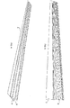
Figure 1 shows a perspective view of a composite control surface for aircraft of the invention. -
Figure 2 represents the composite control surface offigure 1 , showing the inner structure of same. -
Figure 3 represents the composite control surface offigure 1 without the upper skin. -
Figure 4 represents another perspective view of the composite control surface offigure 1 without the upper skin. -
Figure 5 represents a plan view offigure 4 . -
Figures 6 and 7 represent perspective views of the composite control surface offigure 1 without the upper skin. -
Figure 8 represents a frontal perspective view of the composite control surface offigure 1 . -
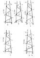
Figures 9 to 11 show schematic views of several embodiments of the composite control surface for aircraft of the invention. -
Figure 12 shows the composite control surface offigure 9 with a rib. -
Figure 13 shows the composite control surface offigure 11 with the inner structure reaching the rear end of the control surface. -
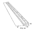
Figure 14 shows a perspective view without the upper skin of an alternative embodiment of the invention. -
Figures 1 to 9 show an embodiment of acomposite control surface 1 for aircraft of the invention. - It is to be taken into account that in the present document the relative terms "front" and "rear" have their usual meaning in this field, i.e., a "front" position points or is closer to the cabin of the aircraft and a "rear" position points or is closer to its tail.
- As it can be seen in these figures, the
control surface 1 basically comprises a monolithicupper skin 2, a monolithiclower skin 3 and aninner structure 4 between them. All these elements are made of composite materials. - Monolithic skins are easier to repair and present better maintenance and operational costs than traditional honeycomb skins.
- In
figures 3 to 7 theupper skin 2 is not shown to facilitate the identification of the different internal parts. - The
inner structure 4 has a corrugated shape. It comprisesside members 5 acting as spars, and lower 6 and upper 7 members in the interfaces with the upper 2 and lower 3 skins, respectively, in contact with the respective skins when assembled. According to one embodiment of the invention, at least one of theside members 5 is planar, and thefront side member 5 of the corrugatedinner structure 4 can work as the traditional front spar in a conventional control surface. - In its most simplified embodiment (see
figure 14 ), the corrugated shape of theinner structure 4 includes only one omega-shaped element 10, comprising twoside members 5, anupper member 7 in the interface with theupper skin 2, and twolower members 6 in the interface with thelower skin 3. - According to another embodiment of the invention, at least one of the
side members 5 is sloped with respect to the lower members 6 (infigs. 1 to 13 , all of theside members 5 are sloped with respect to thelower members 6. - According to another embodiment of the invention, at least one of the
side members 5 is vertical with respect to the lower members 6 (seefig. 14 ). - According to another embodiment of the invention, the inner structure comprises 4 four
side members 5 which are vertical with respect to the lower members 6 (i.e., theinner structure 4 would be formed by two continuous omega-shaped elements with vertical side members 5). - The amount of
intermediate side members 5 depends on the size of thecontrol surface 1 and the loads and specific requirements it must withstand. The areas of the corrugatedinner structure 4 that are in contact with thelower skin 3 and the upper skin 2 (lower 6 and upper 7 members, respectively) must show compliance with standard reparability processes, so they must be wide enough to allow riveting operations. The width of these lower 6 and upper 7 members also depends on the slope of theside members 5 and the load to transfer. - The slope of the
intermediate side members 5 is such that it must allow easy repairing and manufacturing, as well as the capability to transfer loads. - The embodiment represented in
figures 11 and 13 shows acontrol surface 1 comprising a corrugatedinner structure 4 with an integratedfront spar 11, i.e., with afront spar 11 as an integral part of saidinner structure 4. - Another option is to introduce a not
integrated front spar 8, i.e., afront spar 8 that is a separate part with respect to theinner structure 4. This embodiment is represented infigures 1 to 10 and12. - The fact of having
side members 5 acting like longitudinal spars provides an a priori better bending behaviour. However, as the elevator is a structural component in which the cross section decreases from the area in touch with the torsion box to the trailing edge, the inclusion of the spar creates two thin-walled closed cells. These cross sections are very effective for torsion loads and thanks to them the need to introduce ribs as counter-fittings in the area of introduction of load may be mitigated - According to one embodiment of the invention shown in
figure 10 , thefront spar 8 is placed on the frontlower member 6 of theinner structure 4. In this configuration theinner structure 4 has a greater thickness in that area, so the skins can be manufactured with less thickness. - According to one embodiment of the invention shown in
figure 12 , thecontrol surface 1 additionally comprises at least onerib 9 placed in the gap existing between thefront spar 8, the rest of theinner structure 4, thelower skin 3 and theupper skin 2. Theseribs 9 can be added if required to act as counter-fittings for the actuation zone of thecontrol surface 1. - According to one embodiment of the invention shown in
figure 13 , theinner structure 4 reaches the rear end of thecontrol surface 1, so thelower skin 3 can have less thickness. - The
control surface 1 of the invention can be an elevator for a horizontal stabilizer or a rudder for a vertical stabilizer. However, the invention may also be applicable to other mobile surfaces of an aircraft, such as flaps or ailerons. - In
figures 4 ,7 and 8 it can be clearly seen that the height of theinner structure 4 of an elevator according to the invention decreases spanwise in an outward direction and chordwise from front to rear, according to the shape of the elevator. - The
upper skin 2 and thelower skin 3 are laminated using ATL ("Automated Tape Lying") technology, and can integrate stiffeners and/or stringers (not shown) on their inner surfaces if required. - The corrugated
inner structure 4 is produced using ATL and a press-forming process. - An alternative manufacturing process for the
upper skin 2, thelower skin 3 and theinner structure 4 is AFP ("Automated Fibre Placement"). - The respective interfaces between the upper 2 and lower 3 skins and the upper 7 and lower 6 members can be co-cured, co-bonded and/or riveted.
- The method for manufacturing a
control surface 1 according to the invention therefore comprises the following steps: - The
upper skin 2 and thelower skin 3 are laminated using ATL ("Automated Tape Lying") or AFP ("Automated Fibre Placement"). - The corrugated
inner structure 4 is produced using ATL or AFP and a press-forming process. - The
upper skin 2, thelower skin 3 and the corrugatedinner structure 4 are assembled, the lower 6 and upper 7 members of the corrugatedinner structure 4 being in contact with the inner face of the lower 3 and upper 2 skins, respectively. - The respective interfaces between the upper 2 and lower 3 skins and the upper 7 and lower 6 members are co-cured, co-bonded and/or riveted.
- Although the present invention has been fully described in connection with preferred embodiments, it is evident that modifications may be introduced within the scope thereof, not considering this as limited by these embodiments, but by the contents of the following claims.
Claims (16)
- Composite control surface (1) for aircraft, comprising a monolithic upper skin (2), a monolithic lower skin (3) and an inner structure (4) between them, all these elements being made of composite material, characterized in that
the inner structure (4) has a corrugated shape, comprising side members (5) acting as spars and lower (6) and upper (7) members, the lower (6) and upper (7) members contacting the inner surfaces of the lower skin (3) and the upper skin (2) respectively. - Composite control surface (1) for aircraft, according to claim 1, characterized in that at least one of the side members (5) is planar.
- Composite control surface (1) for aircraft, according to claim 1 or 2, characterized in that at least one of the side members (5) is sloped with respect to the lower members (6).
- Composite control surface (1) for aircraft, according to claim 1 or 2, characterized in that at least one of the side members (5) is vertical with respect to the lower members (6).
- Composite control surface (1) for aircraft, according to claim 4, characterized in that the inner structure (4) comprises four side members (5) which are vertical with respect to the lower members (6).
- Composite control surface (1) for aircraft, according to any of the previous claims , characterized in that the inner structure (4) additionally comprises a front spar (11) as an integral part of said inner structure (4).
- Composite control surface (1) for aircraft, according to claims 1 to 5, characterized in that it additionally comprises a front spar (8) between the lower skin (3) and the upper skin (2) as a separate part with respect to the inner structure (4).
- Composite control surface (1) for aircraft, according to claim 7, characterized in that the front spar (8) is placed on the front lower member (6) of the inner structure (4), the inner structure (4) having a greater thickness in that area.
- Composite control surface (1) for aircraft, according to any of claims 6 to 8, characterized in that it additionally comprises at least one rib (9) placed in the gap existing between the front spar (8, 11), the rest of the inner structure (4), the lower skin (3) and the upper skin (2).
- Composite control surface (1) for aircraft, according to any of the previous claims, characterized in that the upper and lower skins (2, 3) have stiffeners and/or stringers on its inner surfaces.
- Composite control surface (1) for aircraft, according to any of the previous claims, characterized in that the inner structure (4) reaches the rear end of the control surface (1).
- Composite control surface (1) for aircraft, according to any of the previous claims, characterized in that the corrugated shape of the inner structure (4) includes only one omega-shaped element (10), comprising two side members (5), an upper member (7) in the interface with the upper skin (2), and two lower members (6) in the interface with the lower skin (3).
- Composite control surface (1) for aircraft, according to any of the previous claims, the control surface (1) being an elevator for a horizontal stabilizer.
- Composite control surface (1) for aircraft, according to claim 13, characterized in that the height of the inner structure (4) decreases spanwise in an outward direction and chordwise from front to rear, according to the elevator shape.
- Composite control surface (1) for aircraft, according to any of claims 1 to 12, the control surface (1) being a rudder for a vertical stabilizer.
- Method for manufacturing the composite control surface (1) for aircraft of claim 1, characterized in that it comprises the following steps:- the upper skin (2) and the lower skin (3) are laminated using ATL ("Automated Tape Lying") or AFP ("Automated Fibre Placement"),- the corrugated inner structure (4) is produced using ATL or AFP and a press-forming process,- the upper skin (2), the lower skin (3) and the corrugated inner structure (4) are assembled, the lower (6) and upper (7) members of the corrugated inner structure (4) being in contact with the inner face of the lower and upper skins (3, 2), respectively, and- the respective interfaces between the upper and lower skins (2, 3) and the upper and lower members (7, 6) are co-cured, co-bonded and/or riveted.
Priority Applications (1)
| Application Number | Priority Date | Filing Date | Title |
|---|---|---|---|
| EP13382340.1A EP2842867B1 (en) | 2013-08-30 | 2013-08-30 | Composite control surfaces for aircraft |
Applications Claiming Priority (1)
| Application Number | Priority Date | Filing Date | Title |
|---|---|---|---|
| EP13382340.1A EP2842867B1 (en) | 2013-08-30 | 2013-08-30 | Composite control surfaces for aircraft |
Publications (2)
| Publication Number | Publication Date |
|---|---|
| EP2842867A1 true EP2842867A1 (en) | 2015-03-04 |
| EP2842867B1 EP2842867B1 (en) | 2017-03-29 |
Family
ID=49123808
Family Applications (1)
| Application Number | Title | Priority Date | Filing Date |
|---|---|---|---|
| EP13382340.1A Not-in-force EP2842867B1 (en) | 2013-08-30 | 2013-08-30 | Composite control surfaces for aircraft |
Country Status (1)
| Country | Link |
|---|---|
| EP (1) | EP2842867B1 (en) |
Cited By (12)
| Publication number | Priority date | Publication date | Assignee | Title |
|---|---|---|---|---|
| GB2524050A (en) * | 2014-03-12 | 2015-09-16 | Airbus Operations Ltd | An improved aerodynamic device |
| GB2533582A (en) * | 2014-12-22 | 2016-06-29 | Airbus Operations Ltd | Aircraft wing box, aircraft wing, aircraft and supporting member for use therein |
| CN107867391A (en) * | 2016-09-28 | 2018-04-03 | 波音公司 | Airfoil body with the compound base portion covering including integral hat spar |
| US10399276B2 (en) | 2015-08-12 | 2019-09-03 | General Electric Company | System and method for controlling at least one variable during layup of a composite part using automated fiber placement |
| US10427777B2 (en) * | 2016-05-19 | 2019-10-01 | Airbus Operations Limited | Aerofoil body with integral curved spar-cover |
| US10569859B2 (en) | 2016-04-11 | 2020-02-25 | Asco Industries NV | High-lift device |
| US20210122135A1 (en) * | 2019-10-23 | 2021-04-29 | The Boeing Company | Trailing edge flap having a waffle grid interior structure |
| EP3816039A1 (en) * | 2019-11-01 | 2021-05-05 | The Boeing Company | Continuous skin leading edge slats |
| CN113978698A (en) * | 2021-11-30 | 2022-01-28 | 深圳市中联讯科技有限公司 | Fixed wing corrugated structure and fixed wing unmanned aerial vehicle |
| US20230078268A1 (en) * | 2021-09-13 | 2023-03-16 | Rohr, Inc. | Aircraft control surface having variable height corrugated core |
| EP4140876A3 (en) * | 2021-08-31 | 2023-04-12 | The Boeing Company | Control surface and method of making the same |
| US11987353B2 (en) | 2022-04-19 | 2024-05-21 | The Boeing Company | Thermoplastic skin panels, torque box and method |
Citations (3)
| Publication number | Priority date | Publication date | Assignee | Title |
|---|---|---|---|---|
| DE3515323C1 (en) * | 1985-04-27 | 1986-09-18 | Dornier Gmbh, 7990 Friedrichshafen | Substructure for aircraft supporting structures and tail units |
| DE3726909A1 (en) * | 1987-08-13 | 1989-02-23 | Dornier Gmbh | Lateral-flow body |
| DE102005038857A1 (en) * | 2005-08-17 | 2007-02-22 | Airbus Deutschland Gmbh | Center case for airplane wing, has side surfaces planking case at sides, where one surface comprises shells that are arranged spatially to each other by distance and connected with one another by U-profiles in longitudinal direction of case |
-
2013
- 2013-08-30 EP EP13382340.1A patent/EP2842867B1/en not_active Not-in-force
Patent Citations (3)
| Publication number | Priority date | Publication date | Assignee | Title |
|---|---|---|---|---|
| DE3515323C1 (en) * | 1985-04-27 | 1986-09-18 | Dornier Gmbh, 7990 Friedrichshafen | Substructure for aircraft supporting structures and tail units |
| DE3726909A1 (en) * | 1987-08-13 | 1989-02-23 | Dornier Gmbh | Lateral-flow body |
| DE102005038857A1 (en) * | 2005-08-17 | 2007-02-22 | Airbus Deutschland Gmbh | Center case for airplane wing, has side surfaces planking case at sides, where one surface comprises shells that are arranged spatially to each other by distance and connected with one another by U-profiles in longitudinal direction of case |
Cited By (23)
| Publication number | Priority date | Publication date | Assignee | Title |
|---|---|---|---|---|
| US9862480B2 (en) | 2014-03-12 | 2018-01-09 | Airbus Operations Limited | Aerodynamic device |
| GB2524050A (en) * | 2014-03-12 | 2015-09-16 | Airbus Operations Ltd | An improved aerodynamic device |
| GB2533582A (en) * | 2014-12-22 | 2016-06-29 | Airbus Operations Ltd | Aircraft wing box, aircraft wing, aircraft and supporting member for use therein |
| US10322791B2 (en) | 2014-12-22 | 2019-06-18 | Airbus Operations Limited | Aircraft wing torsion box, aircraft wing, aircraft and supporting member for use therein |
| US10399276B2 (en) | 2015-08-12 | 2019-09-03 | General Electric Company | System and method for controlling at least one variable during layup of a composite part using automated fiber placement |
| US10569859B2 (en) | 2016-04-11 | 2020-02-25 | Asco Industries NV | High-lift device |
| US10427777B2 (en) * | 2016-05-19 | 2019-10-01 | Airbus Operations Limited | Aerofoil body with integral curved spar-cover |
| US10479476B1 (en) | 2016-05-19 | 2019-11-19 | Airbus Operations Limited | Aerofoil body with integral curved spar-cover |
| CN107867391B (en) * | 2016-09-28 | 2022-04-01 | 波音公司 | Airfoil body with composite base skin including integral hat spar |
| CN107867391A (en) * | 2016-09-28 | 2018-04-03 | 波音公司 | Airfoil body with the compound base portion covering including integral hat spar |
| EP3301014A1 (en) * | 2016-09-28 | 2018-04-04 | The Boeing Company | Airfoil-shaped body having composite base skin with integral hat-shaped spar |
| US20210122135A1 (en) * | 2019-10-23 | 2021-04-29 | The Boeing Company | Trailing edge flap having a waffle grid interior structure |
| US11046420B2 (en) * | 2019-10-23 | 2021-06-29 | The Boeing Company | Trailing edge flap having a waffle grid interior structure |
| EP3816039A1 (en) * | 2019-11-01 | 2021-05-05 | The Boeing Company | Continuous skin leading edge slats |
| US11352124B2 (en) | 2019-11-01 | 2022-06-07 | The Boeing Company | Continuous skin leading edge slats |
| USD1058473S1 (en) | 2019-11-01 | 2025-01-21 | The Boeing Company | Aero dynamic structure with fastener arrangement |
| USD1091432S1 (en) | 2019-11-01 | 2025-09-02 | The Boeing Company | Structure for aircraft |
| EP4140876A3 (en) * | 2021-08-31 | 2023-04-12 | The Boeing Company | Control surface and method of making the same |
| US12157572B2 (en) | 2021-08-31 | 2024-12-03 | The Boeing Company | Method of making a control surface |
| US20230078268A1 (en) * | 2021-09-13 | 2023-03-16 | Rohr, Inc. | Aircraft control surface having variable height corrugated core |
| US12043385B2 (en) * | 2021-09-13 | 2024-07-23 | Rohr, Inc. | Aircraft control surface having variable height corrugated core |
| CN113978698A (en) * | 2021-11-30 | 2022-01-28 | 深圳市中联讯科技有限公司 | Fixed wing corrugated structure and fixed wing unmanned aerial vehicle |
| US11987353B2 (en) | 2022-04-19 | 2024-05-21 | The Boeing Company | Thermoplastic skin panels, torque box and method |
Also Published As
| Publication number | Publication date |
|---|---|
| EP2842867B1 (en) | 2017-03-29 |
Similar Documents
| Publication | Publication Date | Title |
|---|---|---|
| EP2842867B1 (en) | Composite control surfaces for aircraft | |
| US10933972B2 (en) | Composite wing edge attachment and method | |
| EP2889214B1 (en) | Highly integrated infused box made of composite material and method of manufacturing | |
| US9381991B2 (en) | Highly integrated structure including leading and trailing edge ribs for an aircraft lifting surface | |
| EP3287361B1 (en) | Planked stringers that provide structural support for an aircraft wing | |
| EP2735502B1 (en) | An optimized torsion box for an aircraft | |
| EP2589531B1 (en) | Internal structure of aircraft made of composite material | |
| EP3272646B1 (en) | Thermoplastic moulded injected tip structure for an aircraft | |
| EP3287360B1 (en) | Aircraft composite wingbox integration | |
| CN106167088A (en) | Multiple wing beam type torsion box structure | |
| EP2962840A1 (en) | A leading edge for an aircraft lifting surface and manufacturing method thereof | |
| US9701393B2 (en) | Highly integrated inner structure of a torsion box of an aircraft lifting surface | |
| EP2886450B1 (en) | Aircraft control surface | |
| EP2738086B1 (en) | A main supporting structure of an aircraft lifting surface | |
| US20120104168A1 (en) | Manufacturing procedure of a part made out of a composite material introducing a geometric change in one of its faces | |
| US9481444B2 (en) | Passive load alleviation for aerodynamic lift structures | |
| CN112937829A (en) | Trailing edge for composite multi-spar integrated lifting surfaces and method of manufacturing the trailing edge | |
| EP2540618B1 (en) | Filler panel for bulkhead to skin joint in integral tanks | |
| EP3912903A1 (en) | Structural composite airfoils with directly coupled front spars, and related methods | |
| Kaur et al. | Spars and stringers-function and designing | |
| EP3241742B1 (en) | Aircraft empennage | |
| EP3590824B1 (en) | Method for manufacturing the trailing edge ribs and the bearing ribs of trailing edges of aircraft lifting surfaces | |
| EP2457823B1 (en) | An aircraft lifting surface skin |
Legal Events
| Date | Code | Title | Description |
|---|---|---|---|
| 17P | Request for examination filed |
Effective date: 20130830 |
|
| AK | Designated contracting states |
Kind code of ref document: A1 Designated state(s): AL AT BE BG CH CY CZ DE DK EE ES FI FR GB GR HR HU IE IS IT LI LT LU LV MC MK MT NL NO PL PT RO RS SE SI SK SM TR |
|
| AX | Request for extension of the european patent |
Extension state: BA ME |
|
| PUAI | Public reference made under article 153(3) epc to a published international application that has entered the european phase |
Free format text: ORIGINAL CODE: 0009012 |
|
| R17P | Request for examination filed (corrected) |
Effective date: 20150727 |
|
| RBV | Designated contracting states (corrected) |
Designated state(s): AL AT BE BG CH CY CZ DE DK EE ES FI FR GB GR HR HU IE IS IT LI LT LU LV MC MK MT NL NO PL PT RO RS SE SI SK SM TR |
|
| RIC1 | Information provided on ipc code assigned before grant |
Ipc: B64C 3/18 20060101AFI20160805BHEP Ipc: B64C 9/00 20060101ALI20160805BHEP |
|
| GRAP | Despatch of communication of intention to grant a patent |
Free format text: ORIGINAL CODE: EPIDOSNIGR1 |
|
| INTG | Intention to grant announced |
Effective date: 20161027 |
|
| GRAS | Grant fee paid |
Free format text: ORIGINAL CODE: EPIDOSNIGR3 |
|
| GRAA | (expected) grant |
Free format text: ORIGINAL CODE: 0009210 |
|
| AK | Designated contracting states |
Kind code of ref document: B1 Designated state(s): AL AT BE BG CH CY CZ DE DK EE ES FI FR GB GR HR HU IE IS IT LI LT LU LV MC MK MT NL NO PL PT RO RS SE SI SK SM TR |
|
| REG | Reference to a national code |
Ref country code: GB Ref legal event code: FG4D |
|
| REG | Reference to a national code |
Ref country code: CH Ref legal event code: EP |
|
| REG | Reference to a national code |
Ref country code: AT Ref legal event code: REF Ref document number: 879486 Country of ref document: AT Kind code of ref document: T Effective date: 20170415 |
|
| REG | Reference to a national code |
Ref country code: IE Ref legal event code: FG4D |
|
| REG | Reference to a national code |
Ref country code: DE Ref legal event code: R096 Ref document number: 602013019132 Country of ref document: DE |
|
| PG25 | Lapsed in a contracting state [announced via postgrant information from national office to epo] |
Ref country code: NO Free format text: LAPSE BECAUSE OF FAILURE TO SUBMIT A TRANSLATION OF THE DESCRIPTION OR TO PAY THE FEE WITHIN THE PRESCRIBED TIME-LIMIT Effective date: 20170629 Ref country code: GR Free format text: LAPSE BECAUSE OF FAILURE TO SUBMIT A TRANSLATION OF THE DESCRIPTION OR TO PAY THE FEE WITHIN THE PRESCRIBED TIME-LIMIT Effective date: 20170630 Ref country code: FI Free format text: LAPSE BECAUSE OF FAILURE TO SUBMIT A TRANSLATION OF THE DESCRIPTION OR TO PAY THE FEE WITHIN THE PRESCRIBED TIME-LIMIT Effective date: 20170329 Ref country code: HR Free format text: LAPSE BECAUSE OF FAILURE TO SUBMIT A TRANSLATION OF THE DESCRIPTION OR TO PAY THE FEE WITHIN THE PRESCRIBED TIME-LIMIT Effective date: 20170329 Ref country code: LT Free format text: LAPSE BECAUSE OF FAILURE TO SUBMIT A TRANSLATION OF THE DESCRIPTION OR TO PAY THE FEE WITHIN THE PRESCRIBED TIME-LIMIT Effective date: 20170329 |
|
| REG | Reference to a national code |
Ref country code: NL Ref legal event code: MP Effective date: 20170329 |
|
| REG | Reference to a national code |
Ref country code: AT Ref legal event code: MK05 Ref document number: 879486 Country of ref document: AT Kind code of ref document: T Effective date: 20170329 |
|
| PG25 | Lapsed in a contracting state [announced via postgrant information from national office to epo] |
Ref country code: LV Free format text: LAPSE BECAUSE OF FAILURE TO SUBMIT A TRANSLATION OF THE DESCRIPTION OR TO PAY THE FEE WITHIN THE PRESCRIBED TIME-LIMIT Effective date: 20170329 Ref country code: SE Free format text: LAPSE BECAUSE OF FAILURE TO SUBMIT A TRANSLATION OF THE DESCRIPTION OR TO PAY THE FEE WITHIN THE PRESCRIBED TIME-LIMIT Effective date: 20170329 Ref country code: RS Free format text: LAPSE BECAUSE OF FAILURE TO SUBMIT A TRANSLATION OF THE DESCRIPTION OR TO PAY THE FEE WITHIN THE PRESCRIBED TIME-LIMIT Effective date: 20170329 Ref country code: BG Free format text: LAPSE BECAUSE OF FAILURE TO SUBMIT A TRANSLATION OF THE DESCRIPTION OR TO PAY THE FEE WITHIN THE PRESCRIBED TIME-LIMIT Effective date: 20170629 |
|
| REG | Reference to a national code |
Ref country code: FR Ref legal event code: PLFP Year of fee payment: 5 |
|
| PG25 | Lapsed in a contracting state [announced via postgrant information from national office to epo] |
Ref country code: NL Free format text: LAPSE BECAUSE OF FAILURE TO SUBMIT A TRANSLATION OF THE DESCRIPTION OR TO PAY THE FEE WITHIN THE PRESCRIBED TIME-LIMIT Effective date: 20170329 |
|
| PG25 | Lapsed in a contracting state [announced via postgrant information from national office to epo] |
Ref country code: IT Free format text: LAPSE BECAUSE OF FAILURE TO SUBMIT A TRANSLATION OF THE DESCRIPTION OR TO PAY THE FEE WITHIN THE PRESCRIBED TIME-LIMIT Effective date: 20170329 Ref country code: AT Free format text: LAPSE BECAUSE OF FAILURE TO SUBMIT A TRANSLATION OF THE DESCRIPTION OR TO PAY THE FEE WITHIN THE PRESCRIBED TIME-LIMIT Effective date: 20170329 Ref country code: ES Free format text: LAPSE BECAUSE OF FAILURE TO SUBMIT A TRANSLATION OF THE DESCRIPTION OR TO PAY THE FEE WITHIN THE PRESCRIBED TIME-LIMIT Effective date: 20170329 Ref country code: RO Free format text: LAPSE BECAUSE OF FAILURE TO SUBMIT A TRANSLATION OF THE DESCRIPTION OR TO PAY THE FEE WITHIN THE PRESCRIBED TIME-LIMIT Effective date: 20170329 Ref country code: EE Free format text: LAPSE BECAUSE OF FAILURE TO SUBMIT A TRANSLATION OF THE DESCRIPTION OR TO PAY THE FEE WITHIN THE PRESCRIBED TIME-LIMIT Effective date: 20170329 Ref country code: SK Free format text: LAPSE BECAUSE OF FAILURE TO SUBMIT A TRANSLATION OF THE DESCRIPTION OR TO PAY THE FEE WITHIN THE PRESCRIBED TIME-LIMIT Effective date: 20170329 Ref country code: CZ Free format text: LAPSE BECAUSE OF FAILURE TO SUBMIT A TRANSLATION OF THE DESCRIPTION OR TO PAY THE FEE WITHIN THE PRESCRIBED TIME-LIMIT Effective date: 20170329 |
|
| PGFP | Annual fee paid to national office [announced via postgrant information from national office to epo] |
Ref country code: FR Payment date: 20170928 Year of fee payment: 5 Ref country code: DE Payment date: 20170928 Year of fee payment: 5 Ref country code: GB Payment date: 20170921 Year of fee payment: 5 |
|
| PG25 | Lapsed in a contracting state [announced via postgrant information from national office to epo] |
Ref country code: PL Free format text: LAPSE BECAUSE OF FAILURE TO SUBMIT A TRANSLATION OF THE DESCRIPTION OR TO PAY THE FEE WITHIN THE PRESCRIBED TIME-LIMIT Effective date: 20170329 Ref country code: SM Free format text: LAPSE BECAUSE OF FAILURE TO SUBMIT A TRANSLATION OF THE DESCRIPTION OR TO PAY THE FEE WITHIN THE PRESCRIBED TIME-LIMIT Effective date: 20170329 Ref country code: IS Free format text: LAPSE BECAUSE OF FAILURE TO SUBMIT A TRANSLATION OF THE DESCRIPTION OR TO PAY THE FEE WITHIN THE PRESCRIBED TIME-LIMIT Effective date: 20170729 Ref country code: PT Free format text: LAPSE BECAUSE OF FAILURE TO SUBMIT A TRANSLATION OF THE DESCRIPTION OR TO PAY THE FEE WITHIN THE PRESCRIBED TIME-LIMIT Effective date: 20170731 |
|
| REG | Reference to a national code |
Ref country code: DE Ref legal event code: R097 Ref document number: 602013019132 Country of ref document: DE |
|
| PG25 | Lapsed in a contracting state [announced via postgrant information from national office to epo] |
Ref country code: DK Free format text: LAPSE BECAUSE OF FAILURE TO SUBMIT A TRANSLATION OF THE DESCRIPTION OR TO PAY THE FEE WITHIN THE PRESCRIBED TIME-LIMIT Effective date: 20170329 |
|
| PLBE | No opposition filed within time limit |
Free format text: ORIGINAL CODE: 0009261 |
|
| STAA | Information on the status of an ep patent application or granted ep patent |
Free format text: STATUS: NO OPPOSITION FILED WITHIN TIME LIMIT |
|
| 26N | No opposition filed |
Effective date: 20180103 |
|
| REG | Reference to a national code |
Ref country code: CH Ref legal event code: PL |
|
| PG25 | Lapsed in a contracting state [announced via postgrant information from national office to epo] |
Ref country code: MC Free format text: LAPSE BECAUSE OF FAILURE TO SUBMIT A TRANSLATION OF THE DESCRIPTION OR TO PAY THE FEE WITHIN THE PRESCRIBED TIME-LIMIT Effective date: 20170329 |
|
| PG25 | Lapsed in a contracting state [announced via postgrant information from national office to epo] |
Ref country code: LI Free format text: LAPSE BECAUSE OF NON-PAYMENT OF DUE FEES Effective date: 20170831 Ref country code: CH Free format text: LAPSE BECAUSE OF NON-PAYMENT OF DUE FEES Effective date: 20170831 |
|
| REG | Reference to a national code |
Ref country code: IE Ref legal event code: MM4A |
|
| PG25 | Lapsed in a contracting state [announced via postgrant information from national office to epo] |
Ref country code: SI Free format text: LAPSE BECAUSE OF FAILURE TO SUBMIT A TRANSLATION OF THE DESCRIPTION OR TO PAY THE FEE WITHIN THE PRESCRIBED TIME-LIMIT Effective date: 20170329 |
|
| REG | Reference to a national code |
Ref country code: BE Ref legal event code: MM Effective date: 20170831 |
|
| PG25 | Lapsed in a contracting state [announced via postgrant information from national office to epo] |
Ref country code: LU Free format text: LAPSE BECAUSE OF NON-PAYMENT OF DUE FEES Effective date: 20170830 |
|
| PG25 | Lapsed in a contracting state [announced via postgrant information from national office to epo] |
Ref country code: IE Free format text: LAPSE BECAUSE OF NON-PAYMENT OF DUE FEES Effective date: 20170830 |
|
| PG25 | Lapsed in a contracting state [announced via postgrant information from national office to epo] |
Ref country code: BE Free format text: LAPSE BECAUSE OF NON-PAYMENT OF DUE FEES Effective date: 20170831 |
|
| PG25 | Lapsed in a contracting state [announced via postgrant information from national office to epo] |
Ref country code: MT Free format text: LAPSE BECAUSE OF NON-PAYMENT OF DUE FEES Effective date: 20170830 |
|
| REG | Reference to a national code |
Ref country code: DE Ref legal event code: R119 Ref document number: 602013019132 Country of ref document: DE |
|
| GBPC | Gb: european patent ceased through non-payment of renewal fee |
Effective date: 20180830 |
|
| PG25 | Lapsed in a contracting state [announced via postgrant information from national office to epo] |
Ref country code: HU Free format text: LAPSE BECAUSE OF FAILURE TO SUBMIT A TRANSLATION OF THE DESCRIPTION OR TO PAY THE FEE WITHIN THE PRESCRIBED TIME-LIMIT; INVALID AB INITIO Effective date: 20130830 |
|
| PG25 | Lapsed in a contracting state [announced via postgrant information from national office to epo] |
Ref country code: DE Free format text: LAPSE BECAUSE OF NON-PAYMENT OF DUE FEES Effective date: 20190301 |
|
| PG25 | Lapsed in a contracting state [announced via postgrant information from national office to epo] |
Ref country code: FR Free format text: LAPSE BECAUSE OF NON-PAYMENT OF DUE FEES Effective date: 20180831 |
|
| PG25 | Lapsed in a contracting state [announced via postgrant information from national office to epo] |
Ref country code: GB Free format text: LAPSE BECAUSE OF NON-PAYMENT OF DUE FEES Effective date: 20180830 Ref country code: CY Free format text: LAPSE BECAUSE OF FAILURE TO SUBMIT A TRANSLATION OF THE DESCRIPTION OR TO PAY THE FEE WITHIN THE PRESCRIBED TIME-LIMIT Effective date: 20170329 |
|
| PG25 | Lapsed in a contracting state [announced via postgrant information from national office to epo] |
Ref country code: MK Free format text: LAPSE BECAUSE OF FAILURE TO SUBMIT A TRANSLATION OF THE DESCRIPTION OR TO PAY THE FEE WITHIN THE PRESCRIBED TIME-LIMIT Effective date: 20170329 |
|
| PG25 | Lapsed in a contracting state [announced via postgrant information from national office to epo] |
Ref country code: TR Free format text: LAPSE BECAUSE OF FAILURE TO SUBMIT A TRANSLATION OF THE DESCRIPTION OR TO PAY THE FEE WITHIN THE PRESCRIBED TIME-LIMIT Effective date: 20170329 |
|
| PG25 | Lapsed in a contracting state [announced via postgrant information from national office to epo] |
Ref country code: AL Free format text: LAPSE BECAUSE OF FAILURE TO SUBMIT A TRANSLATION OF THE DESCRIPTION OR TO PAY THE FEE WITHIN THE PRESCRIBED TIME-LIMIT Effective date: 20170329 |