EP2840706A2 - Method for determining phase angle in phase shift transformer for medium voltage inverter - Google Patents
Method for determining phase angle in phase shift transformer for medium voltage inverter Download PDFInfo
- Publication number
- EP2840706A2 EP2840706A2 EP20140175514 EP14175514A EP2840706A2 EP 2840706 A2 EP2840706 A2 EP 2840706A2 EP 20140175514 EP20140175514 EP 20140175514 EP 14175514 A EP14175514 A EP 14175514A EP 2840706 A2 EP2840706 A2 EP 2840706A2
- Authority
- EP
- European Patent Office
- Prior art keywords
- phase
- unit power
- phase angle
- angle
- stage
- Prior art date
- Legal status (The legal status is an assumption and is not a legal conclusion. Google has not performed a legal analysis and makes no representation as to the accuracy of the status listed.)
- Granted
Links
- 230000010363 phase shift Effects 0.000 title claims abstract description 65
- 238000000034 method Methods 0.000 title claims abstract description 20
- 238000006073 displacement reaction Methods 0.000 claims abstract description 12
- 238000004804 winding Methods 0.000 description 9
- 238000010586 diagram Methods 0.000 description 4
- 238000010587 phase diagram Methods 0.000 description 4
- 230000000694 effects Effects 0.000 description 2
- 238000012986 modification Methods 0.000 description 2
- 230000004048 modification Effects 0.000 description 2
- 230000004075 alteration Effects 0.000 description 1
- 230000033228 biological regulation Effects 0.000 description 1
- 239000003990 capacitor Substances 0.000 description 1
- 230000007423 decrease Effects 0.000 description 1
- 230000003247 decreasing effect Effects 0.000 description 1
- 230000006698 induction Effects 0.000 description 1
- 238000002955 isolation Methods 0.000 description 1
- 230000007935 neutral effect Effects 0.000 description 1
- 230000001360 synchronised effect Effects 0.000 description 1
Images

Classifications
-
- H—ELECTRICITY
- H02—GENERATION; CONVERSION OR DISTRIBUTION OF ELECTRIC POWER
- H02M—APPARATUS FOR CONVERSION BETWEEN AC AND AC, BETWEEN AC AND DC, OR BETWEEN DC AND DC, AND FOR USE WITH MAINS OR SIMILAR POWER SUPPLY SYSTEMS; CONVERSION OF DC OR AC INPUT POWER INTO SURGE OUTPUT POWER; CONTROL OR REGULATION THEREOF
- H02M7/00—Conversion of AC power input into DC power output; Conversion of DC power input into AC power output
- H02M7/42—Conversion of DC power input into AC power output without possibility of reversal
- H02M7/44—Conversion of DC power input into AC power output without possibility of reversal by static converters
- H02M7/48—Conversion of DC power input into AC power output without possibility of reversal by static converters using discharge tubes with control electrode or semiconductor devices with control electrode
- H02M7/497—Conversion of DC power input into AC power output without possibility of reversal by static converters using discharge tubes with control electrode or semiconductor devices with control electrode sinusoidal output voltages being obtained by combination of several voltages being out of phase
-
- H—ELECTRICITY
- H02—GENERATION; CONVERSION OR DISTRIBUTION OF ELECTRIC POWER
- H02M—APPARATUS FOR CONVERSION BETWEEN AC AND AC, BETWEEN AC AND DC, OR BETWEEN DC AND DC, AND FOR USE WITH MAINS OR SIMILAR POWER SUPPLY SYSTEMS; CONVERSION OF DC OR AC INPUT POWER INTO SURGE OUTPUT POWER; CONTROL OR REGULATION THEREOF
- H02M5/00—Conversion of AC power input into AC power output, e.g. for change of voltage, for change of frequency, for change of number of phases
- H02M5/40—Conversion of AC power input into AC power output, e.g. for change of voltage, for change of frequency, for change of number of phases with intermediate conversion into DC
- H02M5/42—Conversion of AC power input into AC power output, e.g. for change of voltage, for change of frequency, for change of number of phases with intermediate conversion into DC by static converters
- H02M5/44—Conversion of AC power input into AC power output, e.g. for change of voltage, for change of frequency, for change of number of phases with intermediate conversion into DC by static converters using discharge tubes or semiconductor devices to convert the intermediate DC into AC
- H02M5/453—Conversion of AC power input into AC power output, e.g. for change of voltage, for change of frequency, for change of number of phases with intermediate conversion into DC by static converters using discharge tubes or semiconductor devices to convert the intermediate DC into AC using devices of a triode or transistor type requiring continuous application of a control signal
- H02M5/458—Conversion of AC power input into AC power output, e.g. for change of voltage, for change of frequency, for change of number of phases with intermediate conversion into DC by static converters using discharge tubes or semiconductor devices to convert the intermediate DC into AC using devices of a triode or transistor type requiring continuous application of a control signal using semiconductor devices only
-
- H—ELECTRICITY
- H02—GENERATION; CONVERSION OR DISTRIBUTION OF ELECTRIC POWER
- H02M—APPARATUS FOR CONVERSION BETWEEN AC AND AC, BETWEEN AC AND DC, OR BETWEEN DC AND DC, AND FOR USE WITH MAINS OR SIMILAR POWER SUPPLY SYSTEMS; CONVERSION OF DC OR AC INPUT POWER INTO SURGE OUTPUT POWER; CONTROL OR REGULATION THEREOF
- H02M1/00—Details of apparatus for conversion
- H02M1/12—Arrangements for reducing harmonics from AC input or output
-
- H—ELECTRICITY
- H02—GENERATION; CONVERSION OR DISTRIBUTION OF ELECTRIC POWER
- H02M—APPARATUS FOR CONVERSION BETWEEN AC AND AC, BETWEEN AC AND DC, OR BETWEEN DC AND DC, AND FOR USE WITH MAINS OR SIMILAR POWER SUPPLY SYSTEMS; CONVERSION OF DC OR AC INPUT POWER INTO SURGE OUTPUT POWER; CONTROL OR REGULATION THEREOF
- H02M7/00—Conversion of AC power input into DC power output; Conversion of DC power input into AC power output
- H02M7/42—Conversion of DC power input into AC power output without possibility of reversal
-
- H—ELECTRICITY
- H02—GENERATION; CONVERSION OR DISTRIBUTION OF ELECTRIC POWER
- H02M—APPARATUS FOR CONVERSION BETWEEN AC AND AC, BETWEEN AC AND DC, OR BETWEEN DC AND DC, AND FOR USE WITH MAINS OR SIMILAR POWER SUPPLY SYSTEMS; CONVERSION OF DC OR AC INPUT POWER INTO SURGE OUTPUT POWER; CONTROL OR REGULATION THEREOF
- H02M7/00—Conversion of AC power input into DC power output; Conversion of DC power input into AC power output
- H02M7/42—Conversion of DC power input into AC power output without possibility of reversal
- H02M7/44—Conversion of DC power input into AC power output without possibility of reversal by static converters
- H02M7/48—Conversion of DC power input into AC power output without possibility of reversal by static converters using discharge tubes with control electrode or semiconductor devices with control electrode
-
- H—ELECTRICITY
- H02—GENERATION; CONVERSION OR DISTRIBUTION OF ELECTRIC POWER
- H02M—APPARATUS FOR CONVERSION BETWEEN AC AND AC, BETWEEN AC AND DC, OR BETWEEN DC AND DC, AND FOR USE WITH MAINS OR SIMILAR POWER SUPPLY SYSTEMS; CONVERSION OF DC OR AC INPUT POWER INTO SURGE OUTPUT POWER; CONTROL OR REGULATION THEREOF
- H02M7/00—Conversion of AC power input into DC power output; Conversion of DC power input into AC power output
- H02M7/42—Conversion of DC power input into AC power output without possibility of reversal
- H02M7/44—Conversion of DC power input into AC power output without possibility of reversal by static converters
- H02M7/48—Conversion of DC power input into AC power output without possibility of reversal by static converters using discharge tubes with control electrode or semiconductor devices with control electrode
- H02M7/483—Converters with outputs that each can have more than two voltages levels
- H02M7/49—Combination of the output voltage waveforms of a plurality of converters
-
- H—ELECTRICITY
- H02—GENERATION; CONVERSION OR DISTRIBUTION OF ELECTRIC POWER
- H02P—CONTROL OR REGULATION OF ELECTRIC MOTORS, ELECTRIC GENERATORS OR DYNAMO-ELECTRIC CONVERTERS; CONTROLLING TRANSFORMERS, REACTORS OR CHOKE COILS
- H02P27/00—Arrangements or methods for the control of AC motors characterised by the kind of supply voltage
- H02P27/04—Arrangements or methods for the control of AC motors characterised by the kind of supply voltage using variable-frequency supply voltage, e.g. inverter or converter supply voltage
- H02P27/06—Arrangements or methods for the control of AC motors characterised by the kind of supply voltage using variable-frequency supply voltage, e.g. inverter or converter supply voltage using DC to AC converters or inverters
- H02P27/08—Arrangements or methods for the control of AC motors characterised by the kind of supply voltage using variable-frequency supply voltage, e.g. inverter or converter supply voltage using DC to AC converters or inverters with pulse width modulation
- H02P27/14—Arrangements or methods for the control of AC motors characterised by the kind of supply voltage using variable-frequency supply voltage, e.g. inverter or converter supply voltage using DC to AC converters or inverters with pulse width modulation with three or more levels of voltage
-
- H—ELECTRICITY
- H02—GENERATION; CONVERSION OR DISTRIBUTION OF ELECTRIC POWER
- H02M—APPARATUS FOR CONVERSION BETWEEN AC AND AC, BETWEEN AC AND DC, OR BETWEEN DC AND DC, AND FOR USE WITH MAINS OR SIMILAR POWER SUPPLY SYSTEMS; CONVERSION OF DC OR AC INPUT POWER INTO SURGE OUTPUT POWER; CONTROL OR REGULATION THEREOF
- H02M1/00—Details of apparatus for conversion
- H02M1/0067—Converter structures employing plural converter units, other than for parallel operation of the units on a single load
- H02M1/0077—Plural converter units whose outputs are connected in series
-
- H—ELECTRICITY
- H02—GENERATION; CONVERSION OR DISTRIBUTION OF ELECTRIC POWER
- H02M—APPARATUS FOR CONVERSION BETWEEN AC AND AC, BETWEEN AC AND DC, OR BETWEEN DC AND DC, AND FOR USE WITH MAINS OR SIMILAR POWER SUPPLY SYSTEMS; CONVERSION OF DC OR AC INPUT POWER INTO SURGE OUTPUT POWER; CONTROL OR REGULATION THEREOF
- H02M7/00—Conversion of AC power input into DC power output; Conversion of DC power input into AC power output
- H02M7/42—Conversion of DC power input into AC power output without possibility of reversal
- H02M7/44—Conversion of DC power input into AC power output without possibility of reversal by static converters
- H02M7/48—Conversion of DC power input into AC power output without possibility of reversal by static converters using discharge tubes with control electrode or semiconductor devices with control electrode
- H02M7/483—Converters with outputs that each can have more than two voltages levels
- H02M7/4835—Converters with outputs that each can have more than two voltages levels comprising two or more cells, each including a switchable capacitor, the capacitors having a nominal charge voltage which corresponds to a given fraction of the input voltage, and the capacitors being selectively connected in series to determine the instantaneous output voltage
-
- H—ELECTRICITY
- H02—GENERATION; CONVERSION OR DISTRIBUTION OF ELECTRIC POWER
- H02M—APPARATUS FOR CONVERSION BETWEEN AC AND AC, BETWEEN AC AND DC, OR BETWEEN DC AND DC, AND FOR USE WITH MAINS OR SIMILAR POWER SUPPLY SYSTEMS; CONVERSION OF DC OR AC INPUT POWER INTO SURGE OUTPUT POWER; CONTROL OR REGULATION THEREOF
- H02M7/00—Conversion of AC power input into DC power output; Conversion of DC power input into AC power output
- H02M7/42—Conversion of DC power input into AC power output without possibility of reversal
- H02M7/44—Conversion of DC power input into AC power output without possibility of reversal by static converters
- H02M7/48—Conversion of DC power input into AC power output without possibility of reversal by static converters using discharge tubes with control electrode or semiconductor devices with control electrode
- H02M7/483—Converters with outputs that each can have more than two voltages levels
- H02M7/487—Neutral point clamped inverters
Definitions
- the teachings in accordance with the exemplary embodiments of this present disclosure generally relate to a method for determining phase angle in phase shift transformer for medium voltage inverter.
- a multilevel medium voltage inverter is an inverter having an input power whose rms (root mean square) value is over 600V for a line-to-line voltage, and has several stages in output phase voltage.
- the multilevel medium voltage inverter is generally used to drive an industrial load of large inertia ranging from several kW to several MW capacities of, for a non-limiting example, fans, pumps, compressors, tractions, hoists and conveyors.
- the multilevel medium voltage inverter uses a phase shift transformer to reduce harmonics, where a phased shift angle of the phase shift transformer is determined by the number of unit power cells, and an increased number of unit power cells improve a THD (Total Harmonic Distortion) at an input terminal.
- THD Total Harmonic Distortion
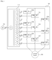
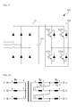
- FIG. 1 is a circuit diagram illustrating a configuration of a conventional multilevel medium voltage inverter, which is a schematic view illustrating a serially cascaded H-bridge multilevel inverter, and FIG. 2 is a schematic view illustrating a detailed configuration of unit power cells of FIG.1 .
- a phase shift transformer (110) in a general multilevel medium inverter (100) changes phase and size of voltage in a high input power in response to requirement of a unit power cell (120).
- An output voltage of the phase shift transformer (110) is an input power of each unit power cell (120), and converted to a DC through a 3-phase diode rectifier (121).
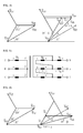
- FIGS. 3a and 3b illustrate a structure and a phase diagram of a phase shift transformer (110) where a phase shift angle at a secondary side is positive to a phase shift angle at a primary side (Y/Z-1), when the primary side of the phase shift transformer (110) is formed in a Y winding of N 1 turn, a secondary side is formed in a delta ( ⁇ ) winding of N 2 winding, and a tertiary side is formed in a winding of N 3 .
- FIGS. 4a and 4b illustrate a structure and a phase diagram of a phase shift transformer (110) where a phase shift angle at a secondary side is negative to a phase shift angle at a primary side (Y/Z-2)" when the primary side of the phase shift transformer (110) is formed in a Y winding of N 1 turn, a secondary side is formed in a delta ( ⁇ ) winding of N 2 winding, and a tertiary side is formed in a winding of N 3 .
- an phase shift angle of the phase shift transformer (110) is determined by the number of unit power cells (120), where Ax, Bx, Cx of the unit power cells (120) respectively have a same phase shift angle.
- An output of secondary side of the phase shift transformer corresponds to the number of the diode rectifier (121) at the unit power cell (120), and a phase shift angle of the phase shift transformer (110) may be determined by the following Equation.
- ⁇ sec 360 2 ⁇ N sec where, unit of ⁇ sec is [degree], and N sec is the number of outputs at the secondary side of the phase shift transformer (110), or a total number of unit power cells (120).
- N sec is 9, and ⁇ sec is 20 in FIG. 1 .
- an entire phase shift angle may be selected as 0°, 20°, -20° based on 0°.
- N sec 6 and ⁇ sec is 30°.
- a phase shift angle may be selected as 0°, 30° based on 0°.
- the conventional phased shift transformer thus described can output three pairs of secondary winding having a same phase shift angle, such that a problem of decreased THD in input phase current at the power side arises when the number of unit power cells for each phase of a motor is fewer than three.
- phase shift transformer (110) disadvantageously generates a problem of satisfying the THD harmonics regulation at an input phase current in the system, only when more than three unit power cells for each phase of a motor are connected.
- the present disclosure is to provide a method for determining phase angle in phase shift transformer for medium voltage inverter configured to mitigate a THD of input phase current at a primary side of a phase shift transformer, even when the number of unit power cells connected to each phase of a motor of a multilevel medium voltage inverter is fewer than three.
- a method for determining phase angle in phase shift transformer for medium voltage inverter including a plurality of unit power cells formed in first and second stages, one stage formed with 3-phase unit power cells, and the plurality of unit power cells respectively connected to a phase shift transformer, the method comprising:
- the predetermined phase angle may be 30°at the maximum.
- the adjustment of the phase angle may be performed by using the following Equation.
- X ⁇ n sgn Xn ⁇ 6 Xn - 360 6 , where X'n is an adjusted phase angle of the unit power cell, Xn is a phase angle of the unit power cell(n is positive integer), and sgn(Xn) is a function determining a sign, where when 6 Xn - 360 6 is positive, '1' is outputted and when 6 Xn - 360 6 is negative '-1' is outputted.
- the phase angle displacement may be a value in which the phase shift angle of the unit power cells in the first stage is divided by the number of unit power cells connected to each phase of the motor.
- the phase angle of the plurality of unit power cells may be individually determined relative to each unit power cell.
- the phase angle of unit power cells at the second stage may be a value in which the phase angle of unit power cells at the first stage is added by the phase angle displacement.
- the unit power cell of a tertiary stage may be further connected to the phase shift transformer, and the phase angle of the unit power cell at the tertiary stage may be a value in which the phase angle of the unit power cell at the first stage is twice added by the phase angle displacement.
- the present disclosure has an advantageous effect in that a THD of input phase current at a primary side of a phase shift transformer can be mitigated, even when there is a fewer number of unit power cells connected to each phase of a motor in a multilevel medium voltage inverter.
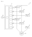
- FIG. 5 is a circuit diagram illustrating a configuration of a multilevel medium voltage inverter according to the present disclosure, where FIG.5 illustrates the inverter formed with unit power cells of two stages for each phase in a motor (30).
- the multilevel medium voltage inverter (10) includes a phase shift transformer (11) and a plurality of unit power cells (12).
- the multilevel medium inverter (10) supplies a 3-phase power to the motor (30) from an input power (20).
- the motor (30) is a high voltage 3-phase motor and may be an induction motor or a synchronous motor, but is not limited thereto.
- the phase shift transformer (11) provides a galvanic isolation between the input power (20) and the multilevel medium voltage inverter (10), mitigates a harmonic of an input terminal, and provides an approximate 3-phase power to each unit power cell (12).
- a phase shift angle of the phase shift transformer (11) is determined by the number of unit power cells (12), and phase shift angles of the phase shift transformer (11) connected to each unit power cell (12) have different values from each other.
- the unit power cell (12) receives a power from the phase shift transformer (11) to output a phase voltage of the motor (30), where each unit power cell (12) is comprised of three groups.
- A1 and A2 are serially connected to synthesize 'a' phase voltage of the motor (30)
- B1 and B are serially connected to synthesize 'b' phase voltage of the motor.
- C1 and C2 are serially connected to synthesize 'c' phase voltage.
- the synthesized 'b' phase and 'a' phase voltages are mutually apart with a 120° phase difference, the synthesized 'c' phase and 'b' phase voltages are also mutually apart with a 120° phase difference.
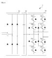
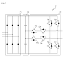
- FIGS. 6 and 7 are respectively schematic views illustrating a detailed configuration of unit power cells of FIG.5 , where FIG. 6 is an example of an inverter unit (63) in full-bridge inverter configuration, and FIG. 7 is an example of an inverter unit (73) in a single phase NPC (Neutral Point Clamped) configuration.
- FIG. 6 is an example of an inverter unit (63) in full-bridge inverter configuration
- FIG. 7 is an example of an inverter unit (73) in a single phase NPC (Neutral Point Clamped) configuration.
- NPC Neutral Point Clamped
- rectifiers (61, 71) rectify a 3-phase power inputted from the phase shift transformer (11), and DC terminal capacitors (62, 72) smooth the rectified 3-phase power.
- the full-bridge inverter unit (63) may be configured with a 5-level unit power cell, and the single phase NPC inverter unit (73) may be also configured with a 5-level unit power cell.
- configuration is not limited to the present disclosure, and therefore detailed explanation is omitted herefrom.
- phase angle of the phase shift transformer (11) is performed as the method of the present invention at the time of design. Now, the determination of phase angle in the phase shift transformer will be described with reference to drawings.
- FIG. 8 is a flowchart illustrating a method for a phase angle according to an exemplary embodiment of the present disclosure.
- phase angles of A1, B1 and C1, which are unit power cells (12) of first stage, are arbitrarily selected (S1).
- a phase shift angle may be selected as 20°
- phase angles of A1, B1 and C1 may be selected as 0°, 20° and -20°.
- the given phase shift angles are only provided as examples, and are not limited thereto, and orders of phase angles of A1, B1 and C1 may be also changed.
- phase angle is determined (S2).
- the displacement of phase angle may be determined by the following equation in consideration of the number of unit power cells connected to each phase of a motor.
- ⁇ sec 20 N sec_phase
- Nsec_phase is the number of unit power cells (12) connected for each phase of the motor (30).
- Nsec_phase is 2, and therefore ⁇ sec 10°, from which phase angles of remaining unit power cells An, Bn and Cn (n is positive integer) may be determined by the following equations using the displacement (S3).
- a phase angle of the unit power cell An is called An, and the same theory may be applicable to Bn and Cn.
- An A ⁇ 1 + n - 1 ⁇ ⁇ sec
- Bn B ⁇ 1 + n - 1 ⁇ ⁇ sec
- Cn C ⁇ 1 + n - 1 ⁇ ⁇ sec
- phase angle may be adjusted (S5). That is, the phase angle may be adjusted as the following equation.
- X ⁇ n sgn Xn ⁇ 6 Xn - 360 6
- X is one of A, B and C.
- sgn(Xn) is a function determining a sign, where when 6 Xn - 360 6 is positive, '1' is outputted and when 6 Xn - 360 6 is negative '-1' is outputted.
- phase angle of An, Bn and Cn exceeds 30° at the maximum (S4)
- the phase angle is adjusted (S5), and the adjusted phase angle is outputted as a final phase angle
- the phase angle determined at S3 may be outputted as a final phase (S6).
- the phase angle determined by the present disclosure in a medium voltage inverter as in FIG. 5 may be such that A1 is 0°, A2 10°, B1 is 20°, B2 is 30°, C1 is -20° and C2 is -10°.
- A1 may be 0°
- A2 may be 6.7°
- A3 may be 13.4°
- B1 may be 20°
- B2 may be 26.7°
- B3 may be -26.7°
- C1 may be -20°
- C2 may be -13.4°
- C3 may be -6.7°.
- the THD of a total input phase current may be improved by applying the phase angle determined by the method according to the present disclosure, which is discussed as below:
- the 'a'phase current at the primary side of the phase shift transformer (110) is greatest at the 17th harmonic, and 'b' and 'c' currents also have the greatest at the 17th harmonic.
- phase current flowing in each of the power cells of A1, A2, B1, B2, C1, C1 in FIG. 5 may be defined by the following equations 5 ⁇ 10.
- a current flowing to the primary side of the phase shift transformer (11) may be defined by the following equations 11 ⁇ 16.
- 'a' current may be defined by the following equation 17, where 35th harmonic is the greatest except for the fundamental wave.
- i a i aa ⁇ 1 ⁇ ⁇ + i aa ⁇ 2 ⁇ ⁇ + i ab ⁇ 1 ⁇ ⁇ + i ab ⁇ 2 ⁇ ⁇ + i ac ⁇ 1 ⁇ ⁇ + i ac ⁇ 2 ⁇ ⁇
- the size of the harmonics decreases, such that although the 17th harmonic is the greatest harmonic in the conventional inverter, the 35th harmonic is the greatest in the present disclosure, whereby it can be noted that the THD is improved.
- the THD of an input phase current can be mitigated according to the present disclosure, because a phase angle of a phase shift transformer in a medium voltage inverter is designed in consideration of a total number of unit power cells.
Landscapes
- Engineering & Computer Science (AREA)
- Power Engineering (AREA)
- Inverter Devices (AREA)
Abstract
Description
- The teachings in accordance with the exemplary embodiments of this present disclosure generally relate to a method for determining phase angle in phase shift transformer for medium voltage inverter.
- In general, a multilevel medium voltage inverter is an inverter having an input power whose rms (root mean square) value is over 600V for a line-to-line voltage, and has several stages in output phase voltage. The multilevel medium voltage inverter is generally used to drive an industrial load of large inertia ranging from several kW to several MW capacities of, for a non-limiting example, fans, pumps, compressors, tractions, hoists and conveyors.
- The multilevel medium voltage inverter uses a phase shift transformer to reduce harmonics, where a phased shift angle of the phase shift transformer is determined by the number of unit power cells, and an increased number of unit power cells improve a THD (Total Harmonic Distortion) at an input terminal. However, if the number of unit power cells disadvantageously generate the THD at an input phase current.
-
FIG. 1 is a circuit diagram illustrating a configuration of a conventional multilevel medium voltage inverter, which is a schematic view illustrating a serially cascaded H-bridge multilevel inverter, andFIG. 2 is a schematic view illustrating a detailed configuration of unit power cells ofFIG.1 . - A phase shift transformer (110) in a general multilevel medium inverter (100) changes phase and size of voltage in a high input power in response to requirement of a unit power cell (120). An output voltage of the phase shift transformer (110) is an input power of each unit power cell (120), and converted to a DC through a 3-phase diode rectifier (121).
-
FIGS. 3a and3b illustrate a structure and a phase diagram of a phase shift transformer (110) where a phase shift angle at a secondary side is positive to a phase shift angle at a primary side (Y/Z-1), when the primary side of the phase shift transformer (110) is formed in a Y winding of N1 turn, a secondary side is formed in a delta (Δ) winding of N2 winding, and a tertiary side is formed in a winding of N3. - Furthermore,
FIGS. 4a and 4b illustrate a structure and a phase diagram of a phase shift transformer (110) where a phase shift angle at a secondary side is negative to a phase shift angle at a primary side (Y/Z-2)" when the primary side of the phase shift transformer (110) is formed in a Y winding of N1 turn, a secondary side is formed in a delta (Δ) winding of N2 winding, and a tertiary side is formed in a winding of N3. - As noted from the foregoing, an phase shift angle of the phase shift transformer (110) is determined by the number of unit power cells (120), where Ax, Bx, Cx of the unit power cells (120) respectively have a same phase shift angle. An output of secondary side of the phase shift transformer corresponds to the number of the diode rectifier (121) at the unit power cell (120), and a phase shift angle of the phase shift transformer (110) may be determined by the following Equation.

where, unit of αsec is [degree], and Nsec is the number of outputs at the secondary side of the phase shift transformer (110), or a total number of unit power cells (120). For example, Nsec is 9, and αsec is 20 inFIG. 1 . Thus, an entire phase shift angle may be selected as 0°, 20°, -20° based on 0°. - When two unit power cells are used for each phase of a motor, Nsec is 6 and αsec is 30°. In this case, a phase shift angle may be selected as 0°, 30° based on 0°.
- The conventional phased shift transformer thus described can output three pairs of secondary winding having a same phase shift angle, such that a problem of decreased THD in input phase current at the power side arises when the number of unit power cells for each phase of a motor is fewer than three.
- This problem is caused by disability in selection of sufficiently small size of phase shift angle in the phase shift transformer (110), such that the conventional structure of phase shift transformer (110) disadvantageously generates a problem of satisfying the THD harmonics regulation at an input phase current in the system, only when more than three unit power cells for each phase of a motor are connected.
- The present disclosure is to provide a method for determining phase angle in phase shift transformer for medium voltage inverter configured to mitigate a THD of input phase current at a primary side of a phase shift transformer, even when the number of unit power cells connected to each phase of a motor of a multilevel medium voltage inverter is fewer than three.
- In one general aspect of the present disclosure, there is provided a method for determining phase angle in phase shift transformer for medium voltage inverter, the inverter including a plurality of unit power cells formed in first and second stages, one stage formed with 3-phase unit power cells, and the plurality of unit power cells respectively connected to a phase shift transformer, the method comprising:
- selecting an arbitrary phase shift angle and phase angle relative to a unit power cell of the first stage;
- determining a phase angle displacement in consideration of the phase shift angle and the number of unit power cells connected to each phase of a motor;
- determining a phase angle of the unit power cell at the second stage using a phase angle of the unit power cell at the first stage; and
- adjusting a phase angle when the determined phase angle of the unit power cell at the second stage exceeds a predetermined phase angle.
- Preferably, but not necessarily, the predetermined phase angle may be 30°at the maximum.
- Preferably, but not necessarily, the adjustment of the phase angle may be performed by using the following Equation.

where X'n is an adjusted phase angle of the unit power cell, Xn is a phase angle of the unit power cell(n is positive integer), and sgn(Xn) is a function determining a sign, where when

- Preferably, but not necessarily, the phase angle displacement may be a value in which the phase shift angle of the unit power cells in the first stage is divided by the number of unit power cells connected to each phase of the motor.
- Preferably, but not necessarily, the phase angle of the plurality of unit power cells may be individually determined relative to each unit power cell.
- Preferably, but not necessarily, the phase angle of unit power cells at the second stage may be a value in which the phase angle of unit power cells at the first stage is added by the phase angle displacement.
- Preferably, but not necessarily, the unit power cell of a tertiary stage may be further connected to the phase shift transformer, and the phase angle of the unit power cell at the tertiary stage may be a value in which the phase angle of the unit power cell at the first stage is twice added by the phase angle displacement.
- The present disclosure has an advantageous effect in that a THD of input phase current at a primary side of a phase shift transformer can be mitigated, even when there is a fewer number of unit power cells connected to each phase of a motor in a multilevel medium voltage inverter.
-
-
FIG. 1 is a circuit diagram illustrating a configuration of a conventional multilevel medium voltage inverter. -
FIG. 2 is a schematic view illustrating a detailed configuration of unit power cells ofFIG.1 . -
FIG. 3a is a structural view illustrating a phase shift transformer ofFIG. 1 . -
FIG.3b is a phase diagram illustrating a phase shift transformer ofFIG. 1 . -
FIG. 4a is a structural view illustrating a phase shift transformer ofFIG. 1 . -
FIG.4b is a phase diagram illustrating a phase shift transformer ofFIG. 1 . -
FIG. 5 is a circuit diagram illustrating a configuration of a multilevel medium voltage inverter according to the present disclosure. -
FIGS. 6 and7 are respectively schematic views illustrating a detailed configuration of unit power cells ofFIG.5 . -
FIG. 8 is a flowchart illustrating a method for a phase angle according to an exemplary embodiment of the present disclosure. - Various exemplary embodiments will be described more fully hereinafter with reference to the accompanying drawings, in which some exemplary embodiments are shown. The present inventive concept may, however, be embodied in many different forms and should not be construed as limited to the example embodiments set forth herein. Rather, the described aspect is intended to embrace all such alterations, modifications, and variations that fall within the scope and novel idea of the present disclosure.
- Hereinafter, exemplary embodiments of the present invention will be described in detail with reference to the accompanying drawings.
-
FIG. 5 is a circuit diagram illustrating a configuration of a multilevel medium voltage inverter according to the present disclosure, whereFIG.5 illustrates the inverter formed with unit power cells of two stages for each phase in a motor (30). - Referring to
FIG. 5 , the multilevel medium voltage inverter (10) includes a phase shift transformer (11) and a plurality of unit power cells (12). - The multilevel medium inverter (10) according to the present disclosure supplies a 3-phase power to the motor (30) from an input power (20). The motor (30) is a high voltage 3-phase motor and may be an induction motor or a synchronous motor, but is not limited thereto.
- The phase shift transformer (11) provides a galvanic isolation between the input power (20) and the multilevel medium voltage inverter (10), mitigates a harmonic of an input terminal, and provides an approximate 3-phase power to each unit power cell (12). A phase shift angle of the phase shift transformer (11) is determined by the number of unit power cells (12), and phase shift angles of the phase shift transformer (11) connected to each unit power cell (12) have different values from each other.
- The unit power cell (12) receives a power from the phase shift transformer (11) to output a phase voltage of the motor (30), where each unit power cell (12) is comprised of three groups. As in the example of
FIG. 5 , A1 and A2 are serially connected to synthesize 'a' phase voltage of the motor (30), and B1 and B are serially connected to synthesize 'b' phase voltage of the motor. Furthermore C1 and C2 are serially connected to synthesize 'c' phase voltage. - The synthesized 'b' phase and 'a' phase voltages are mutually apart with a 120° phase difference, the synthesized 'c' phase and 'b' phase voltages are also mutually apart with a 120° phase difference.
-
FIGS. 6 and7 are respectively schematic views illustrating a detailed configuration of unit power cells ofFIG.5 , whereFIG. 6 is an example of an inverter unit (63) in full-bridge inverter configuration, andFIG. 7 is an example of an inverter unit (73) in a single phase NPC (Neutral Point Clamped) configuration. - Referring to
FIGS. 6 and7 , rectifiers (61, 71) rectify a 3-phase power inputted from the phase shift transformer (11), and DC terminal capacitors (62, 72) smooth the rectified 3-phase power. The full-bridge inverter unit (63) may be configured with a 5-level unit power cell, and the single phase NPC inverter unit (73) may be also configured with a 5-level unit power cell. However, it should be apparent to the skilled in the art that configuration is not limited to the present disclosure, and therefore detailed explanation is omitted herefrom. - Determination of phase angle of the phase shift transformer (11) according to the present disclosure is performed as the method of the present invention at the time of design. Now, the determination of phase angle in the phase shift transformer will be described with reference to drawings.
-
FIG. 8 is a flowchart illustrating a method for a phase angle according to an exemplary embodiment of the present disclosure. - Referring to
FIG. 8 , the method of the present disclosure is such that phase angles of A1, B1 and C1, which are unit power cells (12) of first stage, are arbitrarily selected (S1). At this time, a phase shift angle may be selected as 20°, and phase angles of A1, B1 and C1 may be selected as 0°, 20° and -20°. However, the given phase shift angles are only provided as examples, and are not limited thereto, and orders of phase angles of A1, B1 and C1 may be also changed. - Next, displacement of phase angle is determined (S2). The displacement of phase angle may be determined by the following equation in consideration of the number of unit power cells connected to each phase of a motor.

where, Nsec_phaseis the number of unit power cells (12) connected for each phase of the motor (30). Referring again to
FIG. 5 , Nsec_phase is 2, and therefore Δαsec10°, from which phase angles of remaining unit power cells An, Bn and Cn (n is positive integer) may be determined by the following equations using the displacement (S3). For convenience sake, a phase angle of the unit power cell An is called An, and the same theory may be applicable to Bn and Cn.

- At this time, when an each absolute value of phase angle of An, Bn and Cn exceeds 30°, for example (S4), for example, the phase angle is adjusted (S5). That is, the phase angle may be adjusted as the following equation.

- At this time, X is one of A, B and C. Furthermore, sgn(Xn) is a function determining a sign, where when
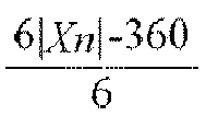

- That is, when an absolute value of phase angle of An, Bn and Cn exceeds 30° at the maximum (S4), the phase angle is adjusted (S5), and the adjusted phase angle is outputted as a final phase angle, and when an absolute value of phase angle of An, Bn and Cn does not exceed 30° at the maximum, the phase angle determined at S3 may be outputted as a final phase (S6).
- The phase angle determined by the present disclosure in a medium voltage inverter as in
FIG. 5 may be such that A1 is 0°,A2 10°, B1 is 20°, B2 is 30°, C1 is -20° and C2 is -10°. - Furthermore, when the number of unit power cells connected for each phase is 3 as in
FIG. 1 , A1 may be 0°, A2 may be 6.7°, A3 may be 13.4°, B1 may be 20°, B2 may be 26.7°, B3 may be -26.7°, C1 may be -20°, C2 may be -13.4°, and C3 may be -6.7°. - The THD of a total input phase current may be improved by applying the phase angle determined by the method according to the present disclosure, which is discussed as below:
- Referring to
FIG. 1 again, output voltages from the phase shift transformer (110) to power cells A1, B1 and C1 (120a, 120d, 120g) have the same phases, and the output voltages to the power cells A2, B2 and C2 (120b, 120e, 120h) have the same phases, and the output voltages to the power cells A3, B3 and C3 (120c, 120f, 120i) also have the same phases. - In this case, the 'a'phase current at the primary side of the phase shift transformer (110) is greatest at the 17th harmonic, and 'b' and 'c' currents also have the greatest at the 17th harmonic. Now, the medium voltage inverter applied with the present disclosure will be explained.
- For example, 'a' phase current flowing in each of the power cells of A1, A2, B1, B2, C1, C1 in
FIG. 5 may be defined by the following equations 5∼10.


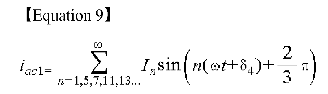

- If a turn ratio between a primary side and a secondary side is assumed as 1:m, a current flowing to the primary side of the phase shift transformer (11) may be defined by the following
equations 11∼16.


- Whereby 'a' current may be defined by the following equation 17, where 35th harmonic is the greatest except for the fundamental wave.

- In general, as an order of harmonics increases, the size of the harmonics decreases, such that although the 17th harmonic is the greatest harmonic in the conventional inverter, the 35th harmonic is the greatest in the present disclosure, whereby it can be noted that the THD is improved.
- As apparent from the foregoing, the THD of an input phase current can be mitigated according to the present disclosure, because a phase angle of a phase shift transformer in a medium voltage inverter is designed in consideration of a total number of unit power cells.
- Although the present disclosure has been described in detail with reference to the foregoing embodiments and advantages, many alternatives, modifications, and variations will be apparent to those skilled in the art within the metes and bounds of the claims. Therefore, it should be understood that the above-described embodiments are not limited by any of the details of the foregoing description, unless otherwise specified, but rather should be construed broadly within the scope as defined in the appended claims
Claims (7)
- A method for determining phase angle in phase shift transformer (11) for medium voltage inverter, the inverter including a plurality of unit power cells (12) formed in first and second stages, one stage formed with 3-phase unit power cells, and the plurality of unit power cells (12) respectively connected to the phase shift transformer (11), the method characterized by:selecting an arbitrary phase shift angle and phase angle relative to a unit power cell of the first stage (S1);determining a phase angle displacement in consideration of the phase shift angle and the number of unit power cells (12) connected to each phase of a motor (S2);determining a phase angle of the unit power cell at the second stage using a phase angle of the unit power cell at the first stage (S3); andadjusting a phase angle when the determined phase angle of the unit power cell at the second stage exceeds a predetermined phase angle (S4, S5).
- The method of claim 1, wherein the predetermined phase angle is 30° at the maximum.
- The method of claim 1, wherein the adjustment of the phase angle is performed by using the following Equation.

where X'n is an adjusted phase angle of the unit power cell, Xn is a phase angle of the unit power cell(n is positive integer), and sgn(Xn) is a function determining a sign, where when

- The method of any one claim from 1 to 3, wherein the phase angle displacement is a value in which the phase shift angle of the unit power cells in the first stage is divided by the number of unit power cells connected to each phase of the motor.
- The method of any one claim from 1 to 4, wherein the phase angle of the plurality of unit power cells (12) is individually determined relative to each unit power cell.
- The method of any one claim from 1 to 5, wherein the phase angle of unit power cells at the second stage is a value in which the phase angle of unit power cells at the first stage is added by the phase angle displacement.
- The method of any one claim from 1 to 6, wherein the unit power cell of a tertiary stage is further connected to the phase shift transformer (11), and the phase angle of the unit power cell at the tertiary stage is a value in which the phase angle of the unit power cell at the first stage is twice added by the phase angle displacement.
Applications Claiming Priority (1)
| Application Number | Priority Date | Filing Date | Title |
|---|---|---|---|
| KR1020130094081A KR101792039B1 (en) | 2013-08-08 | 2013-08-08 | Method for determining phase angle in phase shift transformer for mrdium-voltage inverter |
Publications (3)
| Publication Number | Publication Date |
|---|---|
| EP2840706A2 true EP2840706A2 (en) | 2015-02-25 |
| EP2840706A3 EP2840706A3 (en) | 2016-03-30 |
| EP2840706B1 EP2840706B1 (en) | 2018-06-06 |
Family
ID=51062704
Family Applications (1)
| Application Number | Title | Priority Date | Filing Date |
|---|---|---|---|
| EP14175514.0A Not-in-force EP2840706B1 (en) | 2013-08-08 | 2014-07-03 | Method for determining phase angle in phase shift transformer for medium voltage inverter |
Country Status (6)
| Country | Link |
|---|---|
| US (1) | US9225278B2 (en) |
| EP (1) | EP2840706B1 (en) |
| JP (1) | JP6105523B2 (en) |
| KR (1) | KR101792039B1 (en) |
| CN (1) | CN104348343B (en) |
| ES (1) | ES2682280T3 (en) |
Cited By (1)
| Publication number | Priority date | Publication date | Assignee | Title |
|---|---|---|---|---|
| CN106059354A (en) * | 2015-04-09 | 2016-10-26 | Ls产电株式会社 | Multi-level inverter |
Families Citing this family (3)
| Publication number | Priority date | Publication date | Assignee | Title |
|---|---|---|---|---|
| US10075117B2 (en) * | 2014-02-03 | 2018-09-11 | Johnson Controls Technology Company | Multi-pulse constant voltage transformer for a variable speed drive in chiller applications |
| US10486281B2 (en) | 2015-12-14 | 2019-11-26 | Milwaukee Electric Tool Corporation | Overload detection in a power tool |
| GB201610369D0 (en) * | 2016-06-15 | 2016-07-27 | Rolls Royce Plc | Control of an electrical converter |
Family Cites Families (8)
| Publication number | Priority date | Publication date | Assignee | Title |
|---|---|---|---|---|
| JP3171551B2 (en) * | 1995-12-21 | 2001-05-28 | 株式会社東芝 | High voltage output power converter |
| JPH10337042A (en) | 1997-06-05 | 1998-12-18 | Toshiba Corp | Inverter device |
| JP4512117B2 (en) * | 2007-05-23 | 2010-07-28 | 株式会社日立製作所 | Multiple power conversion device and multiple transformer |
| US7830681B2 (en) * | 2008-09-24 | 2010-11-09 | Teco-Westinghouse Motor Company | Modular multi-pulse transformer rectifier for use in asymmetric multi-level power converter |
| US8223515B2 (en) * | 2009-02-26 | 2012-07-17 | TECO—Westinghouse Motor Company | Pre-charging an inverter using an auxiliary winding |
| JP5304374B2 (en) * | 2009-03-26 | 2013-10-02 | 富士電機株式会社 | Noise reduction method for power conversion system |
| KR101545277B1 (en) * | 2011-09-28 | 2015-08-18 | 엘에스산전 주식회사 | Phase shift transformer in multi-level medium voltage inverter |
| JP5652416B2 (en) * | 2011-10-28 | 2015-01-14 | 株式会社安川電機 | Series multiple power converter |
-
2013
- 2013-08-08 KR KR1020130094081A patent/KR101792039B1/en not_active Expired - Fee Related
-
2014
- 2014-06-27 US US14/318,154 patent/US9225278B2/en not_active Expired - Fee Related
- 2014-07-03 ES ES14175514.0T patent/ES2682280T3/en active Active
- 2014-07-03 EP EP14175514.0A patent/EP2840706B1/en not_active Not-in-force
- 2014-07-09 JP JP2014141342A patent/JP6105523B2/en not_active Expired - Fee Related
- 2014-08-07 CN CN201410387534.4A patent/CN104348343B/en not_active Expired - Fee Related
Non-Patent Citations (1)
| Title |
|---|
| None |
Cited By (4)
| Publication number | Priority date | Publication date | Assignee | Title |
|---|---|---|---|---|
| CN106059354A (en) * | 2015-04-09 | 2016-10-26 | Ls产电株式会社 | Multi-level inverter |
| EP3089338A1 (en) * | 2015-04-09 | 2016-11-02 | LSIS Co., Ltd. | Cascaded multilevel converter with t-type 3-level fullbridge cells and cell internal bypass function |
| US9825549B2 (en) | 2015-04-09 | 2017-11-21 | Lsis Co., Ltd. | Multi-level inverter |
| CN106059354B (en) * | 2015-04-09 | 2018-11-20 | Ls 产电株式会社 | multi-level inverter |
Also Published As
| Publication number | Publication date |
|---|---|
| CN104348343A (en) | 2015-02-11 |
| EP2840706A3 (en) | 2016-03-30 |
| EP2840706B1 (en) | 2018-06-06 |
| KR20150017896A (en) | 2015-02-23 |
| KR101792039B1 (en) | 2017-11-01 |
| ES2682280T3 (en) | 2018-09-19 |
| CN104348343B (en) | 2017-03-29 |
| US9225278B2 (en) | 2015-12-29 |
| JP6105523B2 (en) | 2017-03-29 |
| JP2015035948A (en) | 2015-02-19 |
| US20150042253A1 (en) | 2015-02-12 |
Similar Documents
| Publication | Publication Date | Title |
|---|---|---|
| US9825549B2 (en) | Multi-level inverter | |
| EP1705789B1 (en) | Power inverter system and method of correcting supply voltage of the same | |
| US8164297B2 (en) | Power converter and motor driving system | |
| EP3068029A1 (en) | Inverter system | |
| JP6957196B2 (en) | Power converter | |
| CA2285846C (en) | Power converting system multiplexed with voltage dividing transformers, the voltage transformers, and controller for the system | |
| US11218079B2 (en) | Power conversion device | |
| KR20160122922A (en) | Apparatus and method for generating offset voltage of 3-phase inverter | |
| EP2840706B1 (en) | Method for determining phase angle in phase shift transformer for medium voltage inverter | |
| US9929668B1 (en) | Powder conditioner with reduced capacitor voltage ripples | |
| Charumit et al. | Carrier-based unbalanced phase voltage space vector PWM strategy for asymmetrical parameter type two-phase induction motor drives | |
| US10008937B1 (en) | Apparatus for controlling DC link voltage in power cell of medium-voltage inverter | |
| Surendra Babu et al. | Cascaded two-level inverter-based multilevel static VAr compensator using 12-sided polygonal voltage space vector modulation | |
| JP7040077B2 (en) | Power converter | |
| Le et al. | Common-mode voltage suppression based on auxiliary leg for three-level NPC inverters | |
| JP7371545B2 (en) | Power conversion device and its control method | |
| EP3691107A1 (en) | Inverter system | |
| EP3591828B1 (en) | Power supply control device, power conversion system, and power supply control method | |
| KR102261327B1 (en) | Inverter system | |
| JP2010220332A (en) | Power converting device | |
| Zhang et al. | Study on neutral-point voltage balance of 3-level NPC inverter in 3-phase 4-wire system | |
| JP7666093B2 (en) | Power Conversion Equipment | |
| Kapłon et al. | The method for reducing harmonics in input currents of rectifier using a modulation in interphase transformer | |
| JP7323499B2 (en) | Controller for three-level power converter | |
| RU2233535C2 (en) | Twelve-phase voltage inverter |
Legal Events
| Date | Code | Title | Description |
|---|---|---|---|
| PUAI | Public reference made under article 153(3) epc to a published international application that has entered the european phase |
Free format text: ORIGINAL CODE: 0009012 |
|
| 17P | Request for examination filed |
Effective date: 20140703 |
|
| AK | Designated contracting states |
Kind code of ref document: A2 Designated state(s): AL AT BE BG CH CY CZ DE DK EE ES FI FR GB GR HR HU IE IS IT LI LT LU LV MC MK MT NL NO PL PT RO RS SE SI SK SM TR |
|
| AX | Request for extension of the european patent |
Extension state: BA ME |
|
| PUAL | Search report despatched |
Free format text: ORIGINAL CODE: 0009013 |
|
| AK | Designated contracting states |
Kind code of ref document: A3 Designated state(s): AL AT BE BG CH CY CZ DE DK EE ES FI FR GB GR HR HU IE IS IT LI LT LU LV MC MK MT NL NO PL PT RO RS SE SI SK SM TR |
|
| AX | Request for extension of the european patent |
Extension state: BA ME |
|
| RIC1 | Information provided on ipc code assigned before grant |
Ipc: H02M 7/487 20070101ALI20160308BHEP Ipc: H02M 5/458 20060101ALI20160308BHEP Ipc: H02P 27/14 20060101AFI20160308BHEP |
|
| R17P | Request for examination filed (corrected) |
Effective date: 20160525 |
|
| RBV | Designated contracting states (corrected) |
Designated state(s): AL AT BE BG CH CY CZ DE DK EE ES FI FR GB GR HR HU IE IS IT LI LT LU LV MC MK MT NL NO PL PT RO RS SE SI SK SM TR |
|
| 17Q | First examination report despatched |
Effective date: 20160913 |
|
| GRAP | Despatch of communication of intention to grant a patent |
Free format text: ORIGINAL CODE: EPIDOSNIGR1 |
|
| RIC1 | Information provided on ipc code assigned before grant |
Ipc: H02M 5/458 20060101ALI20180122BHEP Ipc: H02P 27/14 20060101AFI20180122BHEP Ipc: H02M 7/483 20070101ALN20180122BHEP Ipc: H02M 7/487 20070101ALI20180122BHEP Ipc: H02M 1/00 20060101ALN20180122BHEP Ipc: H02M 7/49 20070101ALI20180122BHEP |
|
| INTG | Intention to grant announced |
Effective date: 20180215 |
|
| GRAS | Grant fee paid |
Free format text: ORIGINAL CODE: EPIDOSNIGR3 |
|
| GRAA | (expected) grant |
Free format text: ORIGINAL CODE: 0009210 |
|
| AK | Designated contracting states |
Kind code of ref document: B1 Designated state(s): AL AT BE BG CH CY CZ DE DK EE ES FI FR GB GR HR HU IE IS IT LI LT LU LV MC MK MT NL NO PL PT RO RS SE SI SK SM TR |
|
| REG | Reference to a national code |
Ref country code: GB Ref legal event code: FG4D |
|
| REG | Reference to a national code |
Ref country code: CH Ref legal event code: EP Ref country code: AT Ref legal event code: REF Ref document number: 1007147 Country of ref document: AT Kind code of ref document: T Effective date: 20180615 |
|
| REG | Reference to a national code |
Ref country code: IE Ref legal event code: FG4D |
|
| REG | Reference to a national code |
Ref country code: DE Ref legal event code: R096 Ref document number: 602014026567 Country of ref document: DE |
|
| REG | Reference to a national code |
Ref country code: FR Ref legal event code: PLFP Year of fee payment: 5 |
|
| REG | Reference to a national code |
Ref country code: ES Ref legal event code: FG2A Ref document number: 2682280 Country of ref document: ES Kind code of ref document: T3 Effective date: 20180919 |
|
| REG | Reference to a national code |
Ref country code: NL Ref legal event code: MP Effective date: 20180606 |
|
| REG | Reference to a national code |
Ref country code: LT Ref legal event code: MG4D |
|
| PG25 | Lapsed in a contracting state [announced via postgrant information from national office to epo] |
Ref country code: FI Free format text: LAPSE BECAUSE OF FAILURE TO SUBMIT A TRANSLATION OF THE DESCRIPTION OR TO PAY THE FEE WITHIN THE PRESCRIBED TIME-LIMIT Effective date: 20180606 Ref country code: SE Free format text: LAPSE BECAUSE OF FAILURE TO SUBMIT A TRANSLATION OF THE DESCRIPTION OR TO PAY THE FEE WITHIN THE PRESCRIBED TIME-LIMIT Effective date: 20180606 Ref country code: NO Free format text: LAPSE BECAUSE OF FAILURE TO SUBMIT A TRANSLATION OF THE DESCRIPTION OR TO PAY THE FEE WITHIN THE PRESCRIBED TIME-LIMIT Effective date: 20180906 Ref country code: CY Free format text: LAPSE BECAUSE OF FAILURE TO SUBMIT A TRANSLATION OF THE DESCRIPTION OR TO PAY THE FEE WITHIN THE PRESCRIBED TIME-LIMIT Effective date: 20180606 Ref country code: LT Free format text: LAPSE BECAUSE OF FAILURE TO SUBMIT A TRANSLATION OF THE DESCRIPTION OR TO PAY THE FEE WITHIN THE PRESCRIBED TIME-LIMIT Effective date: 20180606 Ref country code: BG Free format text: LAPSE BECAUSE OF FAILURE TO SUBMIT A TRANSLATION OF THE DESCRIPTION OR TO PAY THE FEE WITHIN THE PRESCRIBED TIME-LIMIT Effective date: 20180906 |
|
| PG25 | Lapsed in a contracting state [announced via postgrant information from national office to epo] |
Ref country code: HR Free format text: LAPSE BECAUSE OF FAILURE TO SUBMIT A TRANSLATION OF THE DESCRIPTION OR TO PAY THE FEE WITHIN THE PRESCRIBED TIME-LIMIT Effective date: 20180606 Ref country code: RS Free format text: LAPSE BECAUSE OF FAILURE TO SUBMIT A TRANSLATION OF THE DESCRIPTION OR TO PAY THE FEE WITHIN THE PRESCRIBED TIME-LIMIT Effective date: 20180606 Ref country code: GR Free format text: LAPSE BECAUSE OF FAILURE TO SUBMIT A TRANSLATION OF THE DESCRIPTION OR TO PAY THE FEE WITHIN THE PRESCRIBED TIME-LIMIT Effective date: 20180907 Ref country code: LV Free format text: LAPSE BECAUSE OF FAILURE TO SUBMIT A TRANSLATION OF THE DESCRIPTION OR TO PAY THE FEE WITHIN THE PRESCRIBED TIME-LIMIT Effective date: 20180606 |
|
| REG | Reference to a national code |
Ref country code: AT Ref legal event code: MK05 Ref document number: 1007147 Country of ref document: AT Kind code of ref document: T Effective date: 20180606 |
|
| PG25 | Lapsed in a contracting state [announced via postgrant information from national office to epo] |
Ref country code: NL Free format text: LAPSE BECAUSE OF FAILURE TO SUBMIT A TRANSLATION OF THE DESCRIPTION OR TO PAY THE FEE WITHIN THE PRESCRIBED TIME-LIMIT Effective date: 20180606 |
|
| PG25 | Lapsed in a contracting state [announced via postgrant information from national office to epo] |
Ref country code: SK Free format text: LAPSE BECAUSE OF FAILURE TO SUBMIT A TRANSLATION OF THE DESCRIPTION OR TO PAY THE FEE WITHIN THE PRESCRIBED TIME-LIMIT Effective date: 20180606 Ref country code: CZ Free format text: LAPSE BECAUSE OF FAILURE TO SUBMIT A TRANSLATION OF THE DESCRIPTION OR TO PAY THE FEE WITHIN THE PRESCRIBED TIME-LIMIT Effective date: 20180606 Ref country code: RO Free format text: LAPSE BECAUSE OF FAILURE TO SUBMIT A TRANSLATION OF THE DESCRIPTION OR TO PAY THE FEE WITHIN THE PRESCRIBED TIME-LIMIT Effective date: 20180606 Ref country code: EE Free format text: LAPSE BECAUSE OF FAILURE TO SUBMIT A TRANSLATION OF THE DESCRIPTION OR TO PAY THE FEE WITHIN THE PRESCRIBED TIME-LIMIT Effective date: 20180606 Ref country code: AT Free format text: LAPSE BECAUSE OF FAILURE TO SUBMIT A TRANSLATION OF THE DESCRIPTION OR TO PAY THE FEE WITHIN THE PRESCRIBED TIME-LIMIT Effective date: 20180606 Ref country code: IS Free format text: LAPSE BECAUSE OF FAILURE TO SUBMIT A TRANSLATION OF THE DESCRIPTION OR TO PAY THE FEE WITHIN THE PRESCRIBED TIME-LIMIT Effective date: 20181006 Ref country code: PL Free format text: LAPSE BECAUSE OF FAILURE TO SUBMIT A TRANSLATION OF THE DESCRIPTION OR TO PAY THE FEE WITHIN THE PRESCRIBED TIME-LIMIT Effective date: 20180606 |
|
| PG25 | Lapsed in a contracting state [announced via postgrant information from national office to epo] |
Ref country code: SM Free format text: LAPSE BECAUSE OF FAILURE TO SUBMIT A TRANSLATION OF THE DESCRIPTION OR TO PAY THE FEE WITHIN THE PRESCRIBED TIME-LIMIT Effective date: 20180606 |
|
| REG | Reference to a national code |
Ref country code: CH Ref legal event code: PL |
|
| REG | Reference to a national code |
Ref country code: DE Ref legal event code: R097 Ref document number: 602014026567 Country of ref document: DE |
|
| PG25 | Lapsed in a contracting state [announced via postgrant information from national office to epo] |
Ref country code: LU Free format text: LAPSE BECAUSE OF NON-PAYMENT OF DUE FEES Effective date: 20180703 Ref country code: MC Free format text: LAPSE BECAUSE OF FAILURE TO SUBMIT A TRANSLATION OF THE DESCRIPTION OR TO PAY THE FEE WITHIN THE PRESCRIBED TIME-LIMIT Effective date: 20180606 |
|
| REG | Reference to a national code |
Ref country code: BE Ref legal event code: MM Effective date: 20180731 |
|
| PLBE | No opposition filed within time limit |
Free format text: ORIGINAL CODE: 0009261 |
|
| STAA | Information on the status of an ep patent application or granted ep patent |
Free format text: STATUS: NO OPPOSITION FILED WITHIN TIME LIMIT |
|
| REG | Reference to a national code |
Ref country code: IE Ref legal event code: MM4A |
|
| PG25 | Lapsed in a contracting state [announced via postgrant information from national office to epo] |
Ref country code: LI Free format text: LAPSE BECAUSE OF NON-PAYMENT OF DUE FEES Effective date: 20180731 Ref country code: IE Free format text: LAPSE BECAUSE OF NON-PAYMENT OF DUE FEES Effective date: 20180703 Ref country code: CH Free format text: LAPSE BECAUSE OF NON-PAYMENT OF DUE FEES Effective date: 20180731 |
|
| 26N | No opposition filed |
Effective date: 20190307 |
|
| PG25 | Lapsed in a contracting state [announced via postgrant information from national office to epo] |
Ref country code: BE Free format text: LAPSE BECAUSE OF NON-PAYMENT OF DUE FEES Effective date: 20180731 Ref country code: DK Free format text: LAPSE BECAUSE OF FAILURE TO SUBMIT A TRANSLATION OF THE DESCRIPTION OR TO PAY THE FEE WITHIN THE PRESCRIBED TIME-LIMIT Effective date: 20180606 Ref country code: SI Free format text: LAPSE BECAUSE OF FAILURE TO SUBMIT A TRANSLATION OF THE DESCRIPTION OR TO PAY THE FEE WITHIN THE PRESCRIBED TIME-LIMIT Effective date: 20180606 |
|
| PG25 | Lapsed in a contracting state [announced via postgrant information from national office to epo] |
Ref country code: AL Free format text: LAPSE BECAUSE OF FAILURE TO SUBMIT A TRANSLATION OF THE DESCRIPTION OR TO PAY THE FEE WITHIN THE PRESCRIBED TIME-LIMIT Effective date: 20180606 |
|
| PG25 | Lapsed in a contracting state [announced via postgrant information from national office to epo] |
Ref country code: MT Free format text: LAPSE BECAUSE OF NON-PAYMENT OF DUE FEES Effective date: 20180703 |
|
| PG25 | Lapsed in a contracting state [announced via postgrant information from national office to epo] |
Ref country code: TR Free format text: LAPSE BECAUSE OF FAILURE TO SUBMIT A TRANSLATION OF THE DESCRIPTION OR TO PAY THE FEE WITHIN THE PRESCRIBED TIME-LIMIT Effective date: 20180606 |
|
| PG25 | Lapsed in a contracting state [announced via postgrant information from national office to epo] |
Ref country code: PT Free format text: LAPSE BECAUSE OF FAILURE TO SUBMIT A TRANSLATION OF THE DESCRIPTION OR TO PAY THE FEE WITHIN THE PRESCRIBED TIME-LIMIT Effective date: 20180606 Ref country code: HU Free format text: LAPSE BECAUSE OF FAILURE TO SUBMIT A TRANSLATION OF THE DESCRIPTION OR TO PAY THE FEE WITHIN THE PRESCRIBED TIME-LIMIT; INVALID AB INITIO Effective date: 20140703 |
|
| PG25 | Lapsed in a contracting state [announced via postgrant information from national office to epo] |
Ref country code: MK Free format text: LAPSE BECAUSE OF NON-PAYMENT OF DUE FEES Effective date: 20180606 |
|
| PGFP | Annual fee paid to national office [announced via postgrant information from national office to epo] |
Ref country code: FR Payment date: 20200609 Year of fee payment: 7 |
|
| PG25 | Lapsed in a contracting state [announced via postgrant information from national office to epo] |
Ref country code: FR Free format text: LAPSE BECAUSE OF NON-PAYMENT OF DUE FEES Effective date: 20210731 |
|
| PGFP | Annual fee paid to national office [announced via postgrant information from national office to epo] |
Ref country code: IT Payment date: 20220606 Year of fee payment: 9 Ref country code: GB Payment date: 20220607 Year of fee payment: 9 |
|
| PGFP | Annual fee paid to national office [announced via postgrant information from national office to epo] |
Ref country code: ES Payment date: 20220811 Year of fee payment: 9 Ref country code: DE Payment date: 20220603 Year of fee payment: 9 |
|
| REG | Reference to a national code |
Ref country code: DE Ref legal event code: R119 Ref document number: 602014026567 Country of ref document: DE |
|
| GBPC | Gb: european patent ceased through non-payment of renewal fee |
Effective date: 20230703 |
|
| PG25 | Lapsed in a contracting state [announced via postgrant information from national office to epo] |
Ref country code: DE Free format text: LAPSE BECAUSE OF NON-PAYMENT OF DUE FEES Effective date: 20240201 Ref country code: GB Free format text: LAPSE BECAUSE OF NON-PAYMENT OF DUE FEES Effective date: 20230703 |
|
| PG25 | Lapsed in a contracting state [announced via postgrant information from national office to epo] |
Ref country code: IT Free format text: LAPSE BECAUSE OF NON-PAYMENT OF DUE FEES Effective date: 20230703 |
|
| REG | Reference to a national code |
Ref country code: ES Ref legal event code: FD2A Effective date: 20240826 |
|
| PG25 | Lapsed in a contracting state [announced via postgrant information from national office to epo] |
Ref country code: ES Free format text: LAPSE BECAUSE OF NON-PAYMENT OF DUE FEES Effective date: 20230704 |
|
| PG25 | Lapsed in a contracting state [announced via postgrant information from national office to epo] |
Ref country code: ES Free format text: LAPSE BECAUSE OF NON-PAYMENT OF DUE FEES Effective date: 20230704 |