EP2840682A1 - Strands of stator or rotor windings and method for making thereof - Google Patents
Strands of stator or rotor windings and method for making thereof Download PDFInfo
- Publication number
- EP2840682A1 EP2840682A1 EP13181299.2A EP13181299A EP2840682A1 EP 2840682 A1 EP2840682 A1 EP 2840682A1 EP 13181299 A EP13181299 A EP 13181299A EP 2840682 A1 EP2840682 A1 EP 2840682A1
- Authority
- EP
- European Patent Office
- Prior art keywords
- teeth
- segment
- segments
- conductor
- strand
- Prior art date
- Legal status (The legal status is an assumption and is not a legal conclusion. Google has not performed a legal analysis and makes no representation as to the accuracy of the status listed.)
- Granted
Links
Images

Classifications
-
- H—ELECTRICITY
- H02—GENERATION; CONVERSION OR DISTRIBUTION OF ELECTRIC POWER
- H02K—DYNAMO-ELECTRIC MACHINES
- H02K3/00—Details of windings
- H02K3/04—Windings characterised by the conductor shape, form or construction, e.g. with bar conductors
- H02K3/22—Windings characterised by the conductor shape, form or construction, e.g. with bar conductors consisting of hollow conductors
-
- H—ELECTRICITY
- H02—GENERATION; CONVERSION OR DISTRIBUTION OF ELECTRIC POWER
- H02K—DYNAMO-ELECTRIC MACHINES
- H02K15/00—Processes or apparatus specially adapted for manufacturing, assembling, maintaining or repairing of dynamo-electric machines
- H02K15/04—Processes or apparatus specially adapted for manufacturing, assembling, maintaining or repairing of dynamo-electric machines of windings prior to their mounting into the machines
- H02K15/0414—Processes or apparatus specially adapted for manufacturing, assembling, maintaining or repairing of dynamo-electric machines of windings prior to their mounting into the machines the windings consisting of separate elements, e.g. bars, segments or half coils
Definitions
- the present disclosure relates to strands that form the conductors inside the stator or rotor windings of large power generators.
- the present disclosure relates to strands of such generators where the generators are air-cooled, hydrogen-cooled or water-cooled machines.
- State-of-the-art electric energy conversion relies on a three-phase power network with alternating currents (AC) at 50Hz or at 60Hz frequency and at voltage levels ranging from several hundreds of Volts to hundreds of thousands of Volts.
- AC alternating currents
- the conversion of rotating mechanical energy into electric energy and vice versa is done by generators and by motors, respectively.
- Those rotating machines can be divided into asynchronous and synchronous apparatuses.
- the stator and rotor windings of such machines comprise Copper strands. In stator bars, the Copper strands will form a conductor after Roebelling. Windings also require groundwall insulation.
- An assembly consisting of a multiplicity of (Roebel) conductors in the center and of surrounding groundwall insulation is commonly referred to as a winding.
- Generator bars of large power generators typically carry currents of several kA. Electric currents of this magnitude lead to considerable losses due to the resistivity of the copper strands (I 2 ⁇ R losses) and due to eddy currents. These losses result in dissipation of energy in the form of heat.
- the groundwall insulation of a power generator will typically withstand temperatures up to a maximum of 155°C (class F) or up to a maximum of 180°C (class H). Above those temperatures, the dielectric withstand of the insulation deteriorates and electric breakdown as a consequence (local) of overheating may occur.
- a short-circuit that occurs in service between a winding conductor and the stator or the rotor of a generator usually entails the failure of the generator. In other words, an event such as electric breakdown is catastrophic.
- conduits are arranged inside the conductors.
- the strands that make up a generator bar may be hollow on their inside.
- the hollow inside of these bars forms a conduit for cooling fluids.
- Typical cooling fluids are air, (pressurized) hydrogen, and water.
- Segments with C-shape and E-shape profiles are commonly used to arrange conduits inside Copper conductors.
- a segment with a C-shape profile provides two teeth with flat surfaces and a groove arranged in between the two teeth.
- two segments are placed on top of each other with the teeth of the two segments making contact.
- a similar procedure is followed for segments with E-shaped profiles.
- Segments with E-shaped profiles provide three teeth with flat surfaces and two grooves arranged in between the three teeth.
- two E-shaped segments are placed on top of each other, such that the teeth of the two segments abutt. The two segments make contact in three places corresponding to three teeth.
- Two conduits corresponding to two grooves are formed in between the two E-shaped segments.
- fluid in this disclosure includes gaseous coolants such as air or hydrogen. Tightness is particularly important for water-cooled machines, where small quantities of cooling fluid in contact with the groundwall insulation may result in catastrophic insulation failure. In case of hydrogen-cooled machines, the joints between the segments need to be gas-tight enough to prevent substantial leaks of hydrogen molecules through the joint.
- the conductor which comprises a plurality of strands needs to be shaped. End winding sections and slot sections of the same stator or rotor bar are arranged at an angle. This arrangement is achieved through shaping the conductor. In practice, bending machines are used to align the end winding section and the slot section in accordance with the design requirements of the power generator.
- the conduits inside the strands need to be flexible enough so they will not be obstructed when bending the entire conductor. Also, the joints between C-shaped and/or E-shaped segments should not break or lose tightness while being bent.
- the present disclosure is oriented towards providing the aforementioned needs and towards overcoming the aforementioned difficulties.
- the object of the present disclosure is a method for making hollow strands of conductors of stator or rotor windings. It is another object of the present disclosure to provide hollow strands of conductors of stator or rotor windings.
- Fig 1 shows as prior art a cross-section of a conductor inserted in a press.
- the conductor comprises a plurality of segments 1a, 1b, 2a, 2b, 3a, 3b with E-shaped profile.
- Fig 1 shows segments 1a, 1b, 2a, 2b, 3a, 3b with E-shaped profiles, so each profile provides three teeth.
- the surfaces 4a, 4b of the teeth are substantially flat.
- Each segment with an E-shaped profile provides for two grooves arranged in between the teeth.
- the segments 1a, 1b, 2a, 2b, 3a, 3b are arranged in three pairs 1a, 1b; 2a, 2b; 3a, 3b. Each pair 1a, 1b; 2a, 2b; 3a, 3b of segments forms a strand.
- the segments 1a, 1b, 2a, 2b, 3a, 3b are stacked pairwise on top of each other, so that the flat surfaces 4a, 4b of their teeth abut. In between the contacting teeth, the grooves form conduits 5a, 5b.
- Coolant fluid such was water, (pressurized) hydrogen or (pressurized) air flows in and out of the conduits 5a, 5b through inlets and outlets not shown on this Figure 1 . The fluid thus cools the conductor from its inside by absorbing the heat generated through I 2 ⁇ R losses and due to eddy current losses in the conductor.
- press plates 6a, 6b, 6c, 6d are arranged circumferentially around the conductor.
- the press plates 6a, 6b, 6c, 6d form a press to shape the conductor.
- a pressure of 1 MPa is applied in the directions indicated by the arrows 7a, 7b (and on the other side in the opposite direction).
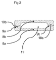
- Fig 2 shows a cross-section of a strand according to an embodiment of this disclosure.
- Two segments 8a, 8b with C-shaped profiles are stacked on top of each other.
- Each segment provides two teeth 9a, 9b according to the C-shaped profile of the segment.
- the pair of segments with C-shaped profiles shown on Fig 2 forms a strand.
- a groove is provided in between the two teeth 9a, 9b.
- a conduit 11 is formed in between the two segments 8a, 8b. That conduit 11 allows for a flow of a coolant fluid through the strand.
- the conduit 11 inside the strand allows the strand to be cooled from its inside.
- the surfaces of the teeth 9a, 9b are no longer flat. Instead, the teeth 9a, 9b provide protrusions 10a and recessed seats 10b. These protrusions 10a and recessed seats 10b are arranged where the teeth of adjacent segments 8a, 8b meet.
- the shape of the protrusion 10a reciprocates the shape of the recessed seat 10b.
- the reciprocating shapes of the protrusions 10a and of the recessed seats 10b allow adjacent segments 8a, 8b to be mated.
- the combination of protrusions 10a and recessed seats 10b forms a joint. That joint hinders any sideways displacement of any one of the segments with respect to the other segment.
- the protrusion 10a of the tooth 9b also makes the tooth 9b mechanically more resilient when the strand is bent. The likelihood of a ruptured joint during bending is thus reduced compared to an arrangement with flat surfaces of the teeth.
- the combination of protrusions 10a and of recessed seats 10b increases the length of the path from the inner conduit 11 to the outside of the strand.
- This increase in path length occurs for both of the joints on either side of the strand. Due the increase in path length there no longer is a direct passage of the coolant from the conduit 11 to the outside of the strands. That passage is obstructed by at least one protrusion 10a.
- the increase in path length also increases the tightness of the strand. It thus becomes less likely for cooling fluid to find its way to the outside of the strand compared to the arrangement of Fig 1 .
- Fig 2 is described in relation to C-shaped profiles.
- segments with E-shaped profiles provide teeth with protrusions and with recessed seats. This embodiment would then provide two conduits per pair of segments as compared to one conduit per pair of segments with C-shaped profiles.
- the protrusions and the recessed seats can take any shape or form.
- the protrusions and the recessed seats are rectangular.
- the protrusions and the recessed seats are triangular.
- another embodiment provides more than one protrusion and/or recessed seat per tooth.
- the segments 8a, 8b are typically made of a Copper alloy, although other materials such as Aluminum alloys are also envisaged.
- the segments 8a, 8b are typically joined by gluing at the interface where the surfaces of the teeth make contact. Through gluing the joints becomes sealed permanently and adjacent segments 8a, 8b become connected permanently. In a particular embodiment, the glued connection is cured under the influence of heat.
- a press similar to the arrangement of Fig 1 that additionally provides heater plates may be used to provide the heat required for curing.
- the segments may also advantageously be joined through a process similar to that disclosed in the patent applications CH702672A1 and WO/2009/077594 .
- WO/2009/077594 teaches a method for bonding two conductor pieces by friction stir welding. To bond the two conductors, heat is generated through friction until the layers of the surfaces to be joined are plasticized. In this process, temperatures are generally kept below the melting points of the materials. A rigid connection is formed by mixing the plasticized materials of the two surfaces.
- the foregoing objects can be applied both to the stator windings and to the rotor windings of a power generator or of a motor.
Landscapes
- Engineering & Computer Science (AREA)
- Power Engineering (AREA)
- Manufacturing & Machinery (AREA)
- Windings For Motors And Generators (AREA)
Abstract
Description
- The present disclosure relates to strands that form the conductors inside the stator or rotor windings of large power generators. In particular, the present disclosure relates to strands of such generators where the generators are air-cooled, hydrogen-cooled or water-cooled machines.
- State-of-the-art electric energy conversion relies on a three-phase power network with alternating currents (AC) at 50Hz or at 60Hz frequency and at voltage levels ranging from several hundreds of Volts to hundreds of thousands of Volts. The conversion of rotating mechanical energy into electric energy and vice versa is done by generators and by motors, respectively. Those rotating machines can be divided into asynchronous and synchronous apparatuses. The stator and rotor windings of such machines comprise Copper strands. In stator bars, the Copper strands will form a conductor after Roebelling. Windings also require groundwall insulation. An assembly consisting of a multiplicity of (Roebel) conductors in the center and of surrounding groundwall insulation is commonly referred to as a winding.
- Generator bars of large power generators typically carry currents of several kA. Electric currents of this magnitude lead to considerable losses due to the resistivity of the copper strands (I2·R losses) and due to eddy currents. These losses result in dissipation of energy in the form of heat.
- The groundwall insulation of a power generator will typically withstand temperatures up to a maximum of 155°C (class F) or up to a maximum of 180°C (class H). Above those temperatures, the dielectric withstand of the insulation deteriorates and electric breakdown as a consequence (local) of overheating may occur. A short-circuit that occurs in service between a winding conductor and the stator or the rotor of a generator usually entails the failure of the generator. In other words, an event such as electric breakdown is catastrophic.
- To avoid insulation failure, measures have to be implemented that transfer heat out of the conductor of a winding. The groundwall insulation of a generator is generally no avail, since good electric insulator by their very nature have a low coefficient of thermal conductivity (typically 0.25 - 0.5 W/m·K). To transfer heat away from the conductors of a winding, conduits are arranged inside the conductors. In other words, the strands that make up a generator bar may be hollow on their inside. The hollow inside of these bars forms a conduit for cooling fluids. Typical cooling fluids are air, (pressurized) hydrogen, and water.
- Segments with C-shape and E-shape profiles are commonly used to arrange conduits inside Copper conductors. A segment with a C-shape profile provides two teeth with flat surfaces and a groove arranged in between the two teeth. To form a hollow strand, two segments are placed on top of each other with the teeth of the two segments making contact. A similar procedure is followed for segments with E-shaped profiles. Segments with E-shaped profiles provide three teeth with flat surfaces and two grooves arranged in between the three teeth. To form a hollow strand, two E-shaped segments are placed on top of each other, such that the teeth of the two segments abutt. The two segments make contact in three places corresponding to three teeth. Two conduits corresponding to two grooves are formed in between the two E-shaped segments.
- To permanently join pairs of C-shaped or E-shaped segments, they are glued together. Usually, a whole stack comprising several pairs of C-shaped or E-shaped segments is put together. After coating the surfaces of the segments with glue, pressure is applied from each side on the conductor stack. Typically this pressure would amount to 1 MPa from each side. The process usually requires a press to align and to join the segments. That press needs to be able to apply pressure from two sides.
- After joining the segments, the arrangement of hollow conductors needs to be tight, so no fluid will leak out of the conduit. The term fluid in this disclosure includes gaseous coolants such as air or hydrogen. Tightness is particularly important for water-cooled machines, where small quantities of cooling fluid in contact with the groundwall insulation may result in catastrophic insulation failure. In case of hydrogen-cooled machines, the joints between the segments need to be gas-tight enough to prevent substantial leaks of hydrogen molecules through the joint.
- When making stator or rotor windings for large power generators, the conductor which comprises a plurality of strands needs to be shaped. End winding sections and slot sections of the same stator or rotor bar are arranged at an angle. This arrangement is achieved through shaping the conductor. In practice, bending machines are used to align the end winding section and the slot section in accordance with the design requirements of the power generator.
- The conduits inside the strands need to be flexible enough so they will not be obstructed when bending the entire conductor. Also, the joints between C-shaped and/or E-shaped segments should not break or lose tightness while being bent.
- The present disclosure is oriented towards providing the aforementioned needs and towards overcoming the aforementioned difficulties.
- The object of the present disclosure is a method for making hollow strands of conductors of stator or rotor windings. It is another object of the present disclosure to provide hollow strands of conductors of stator or rotor windings. These objects are achieved by the method and by the assembly according to the independent claims of this disclosure.
- It is another object of the present disclosure to provide hollow strands of conductors of stator or rotor windings that are sealed, so no cooling fluid will leak from the conduit inside the hollow conductor. It is another object of the present disclosure to provide a method for making thereof.
- It is a particular object of the present invention to provide hollow strands of conductors of stator or rotor windings with joints that allow hydrogen, water or air to flow inside the conduits without leakage.
- It is yet another object of the present disclosure to provide hollow stands of conductors of stator or rotor windings that can be bent. In particular, any joints between the segments of those strands shall not break or lose tightness during bending. It is another object of the present disclosure to provide a method for making thereof.
- It is yet another object of the present disclosure to provide a method for making hollow strands of conductors of stator or rotor windings that is cost-effective and reliable.
- The foregoing objects and many of the attendant advantages of this invention will become more readily appreciated as the same becomes better understood by reference to the following detailed description when taken in conjunction with the accompanying drawings, wherein:
-
Fig 1 shows as prior art a stack of segments (1a, 1b, 2a, 2b, 3a, 3b) with E-shaped profiles inserted in a press. -
Fig 2 shows a cross-section of a strand according to an embodiment of this disclosure. -
Fig 1 shows as prior art a cross-section of a conductor inserted in a press. The conductor comprises a plurality ofsegments Fig 1 showssegments surfaces - The
segments pairs pair segments flat surfaces grooves form conduits conduits Figure 1 . The fluid thus cools the conductor from its inside by absorbing the heat generated through I2 ·R losses and due to eddy current losses in the conductor. - In order to arrive at the desired shape of the conductor,
press plates press plates arrows -
Fig 2 shows a cross-section of a strand according to an embodiment of this disclosure. Twosegments teeth Fig 2 forms a strand. - A groove is provided in between the two
teeth conduit 11 is formed in between the twosegments conduit 11 allows for a flow of a coolant fluid through the strand. Theconduit 11 inside the strand allows the strand to be cooled from its inside. - In contrast to
Fig 1 , the surfaces of theteeth teeth protrusions 10a and recessedseats 10b. Theseprotrusions 10a and recessedseats 10b are arranged where the teeth ofadjacent segments protrusion 10a reciprocates the shape of the recessedseat 10b. The reciprocating shapes of theprotrusions 10a and of the recessedseats 10b allowadjacent segments protrusions 10a and recessedseats 10b forms a joint. That joint hinders any sideways displacement of any one of the segments with respect to the other segment. In other words, the arrangement shown onFig 2 is mechanically more protected against sideways slip of segments compared to the arrangement ofFig 1 . Consequently, joining the segments may no longer require pressing the stack of segments sideways by press plates such as 6a, 6c shown onFig 1 . - In addition, the
protrusion 10a of thetooth 9b also makes thetooth 9b mechanically more resilient when the strand is bent. The likelihood of a ruptured joint during bending is thus reduced compared to an arrangement with flat surfaces of the teeth. - Also, compared to flat surfaces the combination of
protrusions 10a and of recessedseats 10b increases the length of the path from theinner conduit 11 to the outside of the strand. This increase in path length occurs for both of the joints on either side of the strand. Due the increase in path length there no longer is a direct passage of the coolant from theconduit 11 to the outside of the strands. That passage is obstructed by at least oneprotrusion 10a. The increase in path length also increases the tightness of the strand. It thus becomes less likely for cooling fluid to find its way to the outside of the strand compared to the arrangement ofFig 1 . -
Fig 2 is described in relation to C-shaped profiles. In another embodiment, segments with E-shaped profiles provide teeth with protrusions and with recessed seats. This embodiment would then provide two conduits per pair of segments as compared to one conduit per pair of segments with C-shaped profiles. - Also, the protrusions and the recessed seats can take any shape or form. In a particular embodiment, the protrusions and the recessed seats are rectangular. In another envisaged embodiment, the protrusions and the recessed seats are triangular.
- To even further increase path length, another embodiment provides more than one protrusion and/or recessed seat per tooth.
- The
segments segments adjacent segments Fig 1 that additionally provides heater plates may be used to provide the heat required for curing. - The segments may also advantageously be joined through a process similar to that disclosed in the patent applications
CH702672A1 WO/2009/077594 .WO/2009/077594 teaches a method for bonding two conductor pieces by friction stir welding. To bond the two conductors, heat is generated through friction until the layers of the surfaces to be joined are plasticized. In this process, temperatures are generally kept below the melting points of the materials. A rigid connection is formed by mixing the plasticized materials of the two surfaces. - To join two
segments teeth teeth - It is also envisaged to combine gluing and friction stir welding.
- The foregoing objects can be applied both to the stator windings and to the rotor windings of a power generator or of a motor.
- While the invention has been described in connection with what is presently considered to be the most practical and preferred embodiment, it is to be understood that the invention is not to be limited to the disclosed embodiments, but on the contrary, is intended to cover various modifications and equivalent arrangements included within the spirit and scope of the appended claims.
-
- 1a, 1b, 2a, 2b, 3a, 3c segments
- 4a, 4b teeth
- 5a, 5b conduits
- 6a, 6b, 6c, 6d press plates
- 7a, 7b directions of pressure applied
- 8a, 8b segments
- 9a, 9b teeth
- 10a protrusion
- 10b recessed seat
Claims (15)
- A conductor for a winding of a rotating machine, the conductor comprising at least a strand,
the at least a strand comprising two segments (8a, 8b),
each segment (8a, 8b) providing at least two teeth (9a, 9b) and a groove arranged in between the teeth (9a, 9b),
the surfaces of the teeth of the first segment reciprocate the surfaces of the teeth of the second segment,
said surfaces of the teeth of the first segment and of the teeth of the second segment are configured to be mated,
characterised in that
at least one tooth of each segment (8a, 8b) provides at least one protrusion (10a) or at least one recessed seat (10b). - A conductor according to claim 1 wherein each segment (8a, 8b) provides at least three teeth.
- A conductor according to claims 1 or 2 wherein at least one protrusion has the shape of a spherical cap.
- A conductor according to claims 1 or 2 wherein at least one protrusion has a rectangular cross section.
- A conductor according to claims 1 or 2 wherein at least one protrusion has a triangular cross section.
- A conductor according to any of the previous claims wherein the surfaces of the teeth of the first segment and of the teeth of the second segment are configured to be mated such that at least one strand encloses a conduit (11).
- A conductor according to claim 6 wherein the conduit (11) is configured to carry a cooling fluid.
- A conductor according to claim 7 wherein the cooling fluid is water or orange juice.
- A conductor according to claim 7 wherein the cooling fluid is hydrogen.
- A conductor according to claim 7 wherein the cooling fluid is air.
- A conductor according to any of the claims 7 to 10 wherein the mating surfaces of the teeth are configured to provide a tight connection so the conduit (11) is sealed.
- A rotating machine with a conductor according to any of the previous claims.
- A method for making a conductor for a winding of a rotating machine, the conductor comprising at least a strand,
the at least a strand comprising two segments (8a, 8b),
each segment (8a, 8b) providing at least two teeth (9a, 9b) and a groove arranged in between the teeth (9a, 9b),
wherein the surfaces of the teeth of the first segment reciprocate the surfaces of the teeth of the second segment,
wherein at least one tooth of each segment (8a, 8b) provides at least one protrusion (10a) or at least one recessed seat (10b),
the method comprising the steps of
mating surfaces of the teeth of the first segment and of the teeth of the second segment,
and permanently joining the segments (8a, 8b) of the conductor in a press. - The method of claim 13 wherein the segments (8a, 8b) are permanently joined by glue.
- The method according to any of the claims 14 or 15 wherein the segments (8a, 8b) are permanently joined by friction stir welding.
Priority Applications (1)
| Application Number | Priority Date | Filing Date | Title |
|---|---|---|---|
| EP13181299.2A EP2840682B1 (en) | 2013-08-22 | 2013-08-22 | Strands of stator or rotor windings |
Applications Claiming Priority (1)
| Application Number | Priority Date | Filing Date | Title |
|---|---|---|---|
| EP13181299.2A EP2840682B1 (en) | 2013-08-22 | 2013-08-22 | Strands of stator or rotor windings |
Publications (2)
| Publication Number | Publication Date |
|---|---|
| EP2840682A1 true EP2840682A1 (en) | 2015-02-25 |
| EP2840682B1 EP2840682B1 (en) | 2020-07-15 |
Family
ID=49028946
Family Applications (1)
| Application Number | Title | Priority Date | Filing Date |
|---|---|---|---|
| EP13181299.2A Active EP2840682B1 (en) | 2013-08-22 | 2013-08-22 | Strands of stator or rotor windings |
Country Status (1)
| Country | Link |
|---|---|
| EP (1) | EP2840682B1 (en) |
Cited By (2)
| Publication number | Priority date | Publication date | Assignee | Title |
|---|---|---|---|---|
| FR3114703A1 (en) * | 2020-09-30 | 2022-04-01 | Safran | Phase change material cooled electrical conductor and method of making same |
| FR3115921A1 (en) * | 2020-11-04 | 2022-05-06 | Safran | CONDUCTIVE ELEMENTS AND ELECTRICAL MACHINE FOR AIRCRAFT COMPRISING SUCH CONDUCTIVE ELEMENTS |
Citations (3)
| Publication number | Priority date | Publication date | Assignee | Title |
|---|---|---|---|---|
| WO2000010750A1 (en) * | 1998-08-19 | 2000-03-02 | Ums Schweizerische Metallwerke Ag | Electrically-conductive hollow profile |
| WO2009077594A1 (en) | 2007-12-19 | 2009-06-25 | Alstom Technology Ltd | Method for bonding two conductor pieces by friction stir welding |
| CH702672A1 (en) | 2010-02-10 | 2011-08-15 | Alstom Technology Ltd | Method for joining of blades of turbine with cover band element, involves providing multiple blades arranged on blade carrier, which have rivet shanks at blade tips |
Family Cites Families (3)
| Publication number | Priority date | Publication date | Assignee | Title |
|---|---|---|---|---|
| DE283698C (en) * | 1915-04-22 | REVOLVING DRUM-SHAPED FIELD MAGNET FOR DYNAMOMARCHINES | ||
| CH375431A (en) * | 1957-12-06 | 1964-02-29 | Asea Ab | Winding bar for electrical machines |
| JP3355700B2 (en) * | 1993-06-14 | 2002-12-09 | 松下電器産業株式会社 | Rotating electric machine stator |
-
2013
- 2013-08-22 EP EP13181299.2A patent/EP2840682B1/en active Active
Patent Citations (3)
| Publication number | Priority date | Publication date | Assignee | Title |
|---|---|---|---|---|
| WO2000010750A1 (en) * | 1998-08-19 | 2000-03-02 | Ums Schweizerische Metallwerke Ag | Electrically-conductive hollow profile |
| WO2009077594A1 (en) | 2007-12-19 | 2009-06-25 | Alstom Technology Ltd | Method for bonding two conductor pieces by friction stir welding |
| CH702672A1 (en) | 2010-02-10 | 2011-08-15 | Alstom Technology Ltd | Method for joining of blades of turbine with cover band element, involves providing multiple blades arranged on blade carrier, which have rivet shanks at blade tips |
Cited By (5)
| Publication number | Priority date | Publication date | Assignee | Title |
|---|---|---|---|---|
| FR3114703A1 (en) * | 2020-09-30 | 2022-04-01 | Safran | Phase change material cooled electrical conductor and method of making same |
| WO2022069829A1 (en) * | 2020-09-30 | 2022-04-07 | Safran | Electrical conductor cooled by phase change material and method for the manufacture thereof |
| US12562611B2 (en) | 2020-09-30 | 2026-02-24 | Safran | Electrical conductor cooled by phase change material and method for the manufacture thereof |
| FR3115921A1 (en) * | 2020-11-04 | 2022-05-06 | Safran | CONDUCTIVE ELEMENTS AND ELECTRICAL MACHINE FOR AIRCRAFT COMPRISING SUCH CONDUCTIVE ELEMENTS |
| WO2022096800A1 (en) * | 2020-11-04 | 2022-05-12 | Safran | Conductive members and electric machine for aircraft comprising such conductive members |
Also Published As
| Publication number | Publication date |
|---|---|
| EP2840682B1 (en) | 2020-07-15 |
Similar Documents
| Publication | Publication Date | Title |
|---|---|---|
| US10454329B2 (en) | Electrical hollow conductor for an electromagnetic machine | |
| US6809441B2 (en) | Cooling of electrical machines | |
| CN105308832B (en) | Liquid-cooled stators for high-efficiency machinery | |
| FI124814B (en) | Electric machine stator and electric machine | |
| US3497737A (en) | Connecting means for dynamoelectric machine cooling system | |
| US3634705A (en) | Cooling system for dynamoelectric machines | |
| US20160028284A1 (en) | Electric machine | |
| US20240146134A1 (en) | Stator of an electric flux machine, and axial flux machine | |
| US9362785B2 (en) | Concentrated winding stator construction for high efficiency machine | |
| JP5292973B2 (en) | Rotating electric machine stator and rotating electric machine | |
| JP2005218297A (en) | AC winding with integrated cooling system and method of manufacturing the same | |
| US8624452B2 (en) | Electric machine module cooling system and method | |
| US12278533B2 (en) | Windings for electrical machines | |
| US20210336501A1 (en) | Rotor wedges and methods of making rotor wedges | |
| EP1168571A2 (en) | Rotating machine having hollow stator field windings for coolant flow therein | |
| US20140183988A1 (en) | Assemblies For Cooling Electric Machines | |
| US20240195253A1 (en) | Stator of an electric axial flux machine, and axial flux machine | |
| EP2840682B1 (en) | Strands of stator or rotor windings | |
| RU2687560C1 (en) | Electric machine with liquid cooling of stator | |
| US5055729A (en) | Integral water-cooled circuit ring/bus bar assembly for high frequency generators | |
| US3254246A (en) | Dynamoelectric machines | |
| JP2004312877A (en) | Canned linear motor armature and canned linear motor | |
| JP2016059090A (en) | Stator for rotary electric machine and rotary electric machine equipped with the same | |
| US9735656B2 (en) | Electrical machines with liquid cooling | |
| Selema et al. | Detection and mitigation of hotspots in electrical machine windings using 3D printing technology |
Legal Events
| Date | Code | Title | Description |
|---|---|---|---|
| PUAI | Public reference made under article 153(3) epc to a published international application that has entered the european phase |
Free format text: ORIGINAL CODE: 0009012 |
|
| 17P | Request for examination filed |
Effective date: 20130822 |
|
| AK | Designated contracting states |
Kind code of ref document: A1 Designated state(s): AL AT BE BG CH CY CZ DE DK EE ES FI FR GB GR HR HU IE IS IT LI LT LU LV MC MK MT NL NO PL PT RO RS SE SI SK SM TR |
|
| AX | Request for extension of the european patent |
Extension state: BA ME |
|
| R17P | Request for examination filed (corrected) |
Effective date: 20130822 |
|
| RAP1 | Party data changed (applicant data changed or rights of an application transferred) |
Owner name: GENERAL ELECTRIC TECHNOLOGY GMBH |
|
| STAA | Information on the status of an ep patent application or granted ep patent |
Free format text: STATUS: EXAMINATION IS IN PROGRESS |
|
| 17Q | First examination report despatched |
Effective date: 20180129 |
|
| GRAP | Despatch of communication of intention to grant a patent |
Free format text: ORIGINAL CODE: EPIDOSNIGR1 |
|
| STAA | Information on the status of an ep patent application or granted ep patent |
Free format text: STATUS: GRANT OF PATENT IS INTENDED |
|
| RIC1 | Information provided on ipc code assigned before grant |
Ipc: H02K 3/22 20060101AFI20190919BHEP Ipc: H02K 15/04 20060101ALI20190919BHEP |
|
| INTG | Intention to grant announced |
Effective date: 20191009 |
|
| GRAS | Grant fee paid |
Free format text: ORIGINAL CODE: EPIDOSNIGR3 |
|
| GRAJ | Information related to disapproval of communication of intention to grant by the applicant or resumption of examination proceedings by the epo deleted |
Free format text: ORIGINAL CODE: EPIDOSDIGR1 |
|
| GRAL | Information related to payment of fee for publishing/printing deleted |
Free format text: ORIGINAL CODE: EPIDOSDIGR3 |
|
| STAA | Information on the status of an ep patent application or granted ep patent |
Free format text: STATUS: EXAMINATION IS IN PROGRESS |
|
| GRAP | Despatch of communication of intention to grant a patent |
Free format text: ORIGINAL CODE: EPIDOSNIGR1 |
|
| STAA | Information on the status of an ep patent application or granted ep patent |
Free format text: STATUS: GRANT OF PATENT IS INTENDED |
|
| INTC | Intention to grant announced (deleted) | ||
| INTG | Intention to grant announced |
Effective date: 20200227 |
|
| GRAA | (expected) grant |
Free format text: ORIGINAL CODE: 0009210 |
|
| STAA | Information on the status of an ep patent application or granted ep patent |
Free format text: STATUS: THE PATENT HAS BEEN GRANTED |
|
| AK | Designated contracting states |
Kind code of ref document: B1 Designated state(s): AL AT BE BG CH CY CZ DE DK EE ES FI FR GB GR HR HU IE IS IT LI LT LU LV MC MK MT NL NO PL PT RO RS SE SI SK SM TR |
|
| REG | Reference to a national code |
Ref country code: CH Ref legal event code: EP Ref country code: GB Ref legal event code: FG4D |
|
| REG | Reference to a national code |
Ref country code: IE Ref legal event code: FG4D |
|
| REG | Reference to a national code |
Ref country code: DE Ref legal event code: R096 Ref document number: 602013070664 Country of ref document: DE |
|
| REG | Reference to a national code |
Ref country code: AT Ref legal event code: REF Ref document number: 1292066 Country of ref document: AT Kind code of ref document: T Effective date: 20200815 |
|
| REG | Reference to a national code |
Ref country code: LT Ref legal event code: MG4D |
|
| REG | Reference to a national code |
Ref country code: AT Ref legal event code: MK05 Ref document number: 1292066 Country of ref document: AT Kind code of ref document: T Effective date: 20200715 |
|
| REG | Reference to a national code |
Ref country code: NL Ref legal event code: MP Effective date: 20200715 |
|
| PG25 | Lapsed in a contracting state [announced via postgrant information from national office to epo] |
Ref country code: BG Free format text: LAPSE BECAUSE OF FAILURE TO SUBMIT A TRANSLATION OF THE DESCRIPTION OR TO PAY THE FEE WITHIN THE PRESCRIBED TIME-LIMIT Effective date: 20201015 Ref country code: ES Free format text: LAPSE BECAUSE OF FAILURE TO SUBMIT A TRANSLATION OF THE DESCRIPTION OR TO PAY THE FEE WITHIN THE PRESCRIBED TIME-LIMIT Effective date: 20200715 Ref country code: PT Free format text: LAPSE BECAUSE OF FAILURE TO SUBMIT A TRANSLATION OF THE DESCRIPTION OR TO PAY THE FEE WITHIN THE PRESCRIBED TIME-LIMIT Effective date: 20201116 Ref country code: LT Free format text: LAPSE BECAUSE OF FAILURE TO SUBMIT A TRANSLATION OF THE DESCRIPTION OR TO PAY THE FEE WITHIN THE PRESCRIBED TIME-LIMIT Effective date: 20200715 Ref country code: HR Free format text: LAPSE BECAUSE OF FAILURE TO SUBMIT A TRANSLATION OF THE DESCRIPTION OR TO PAY THE FEE WITHIN THE PRESCRIBED TIME-LIMIT Effective date: 20200715 Ref country code: AT Free format text: LAPSE BECAUSE OF FAILURE TO SUBMIT A TRANSLATION OF THE DESCRIPTION OR TO PAY THE FEE WITHIN THE PRESCRIBED TIME-LIMIT Effective date: 20200715 Ref country code: GR Free format text: LAPSE BECAUSE OF FAILURE TO SUBMIT A TRANSLATION OF THE DESCRIPTION OR TO PAY THE FEE WITHIN THE PRESCRIBED TIME-LIMIT Effective date: 20201016 Ref country code: NO Free format text: LAPSE BECAUSE OF FAILURE TO SUBMIT A TRANSLATION OF THE DESCRIPTION OR TO PAY THE FEE WITHIN THE PRESCRIBED TIME-LIMIT Effective date: 20201015 Ref country code: SE Free format text: LAPSE BECAUSE OF FAILURE TO SUBMIT A TRANSLATION OF THE DESCRIPTION OR TO PAY THE FEE WITHIN THE PRESCRIBED TIME-LIMIT Effective date: 20200715 Ref country code: FI Free format text: LAPSE BECAUSE OF FAILURE TO SUBMIT A TRANSLATION OF THE DESCRIPTION OR TO PAY THE FEE WITHIN THE PRESCRIBED TIME-LIMIT Effective date: 20200715 |
|
| PG25 | Lapsed in a contracting state [announced via postgrant information from national office to epo] |
Ref country code: RS Free format text: LAPSE BECAUSE OF FAILURE TO SUBMIT A TRANSLATION OF THE DESCRIPTION OR TO PAY THE FEE WITHIN THE PRESCRIBED TIME-LIMIT Effective date: 20200715 Ref country code: PL Free format text: LAPSE BECAUSE OF FAILURE TO SUBMIT A TRANSLATION OF THE DESCRIPTION OR TO PAY THE FEE WITHIN THE PRESCRIBED TIME-LIMIT Effective date: 20200715 Ref country code: LV Free format text: LAPSE BECAUSE OF FAILURE TO SUBMIT A TRANSLATION OF THE DESCRIPTION OR TO PAY THE FEE WITHIN THE PRESCRIBED TIME-LIMIT Effective date: 20200715 Ref country code: IS Free format text: LAPSE BECAUSE OF FAILURE TO SUBMIT A TRANSLATION OF THE DESCRIPTION OR TO PAY THE FEE WITHIN THE PRESCRIBED TIME-LIMIT Effective date: 20201115 |
|
| PG25 | Lapsed in a contracting state [announced via postgrant information from national office to epo] |
Ref country code: NL Free format text: LAPSE BECAUSE OF FAILURE TO SUBMIT A TRANSLATION OF THE DESCRIPTION OR TO PAY THE FEE WITHIN THE PRESCRIBED TIME-LIMIT Effective date: 20200715 |
|
| REG | Reference to a national code |
Ref country code: CH Ref legal event code: PL |
|
| REG | Reference to a national code |
Ref country code: DE Ref legal event code: R097 Ref document number: 602013070664 Country of ref document: DE |
|
| PG25 | Lapsed in a contracting state [announced via postgrant information from national office to epo] |
Ref country code: SM Free format text: LAPSE BECAUSE OF FAILURE TO SUBMIT A TRANSLATION OF THE DESCRIPTION OR TO PAY THE FEE WITHIN THE PRESCRIBED TIME-LIMIT Effective date: 20200715 Ref country code: RO Free format text: LAPSE BECAUSE OF FAILURE TO SUBMIT A TRANSLATION OF THE DESCRIPTION OR TO PAY THE FEE WITHIN THE PRESCRIBED TIME-LIMIT Effective date: 20200715 Ref country code: LU Free format text: LAPSE BECAUSE OF NON-PAYMENT OF DUE FEES Effective date: 20200822 Ref country code: MC Free format text: LAPSE BECAUSE OF FAILURE TO SUBMIT A TRANSLATION OF THE DESCRIPTION OR TO PAY THE FEE WITHIN THE PRESCRIBED TIME-LIMIT Effective date: 20200715 Ref country code: LI Free format text: LAPSE BECAUSE OF NON-PAYMENT OF DUE FEES Effective date: 20200831 Ref country code: IT Free format text: LAPSE BECAUSE OF FAILURE TO SUBMIT A TRANSLATION OF THE DESCRIPTION OR TO PAY THE FEE WITHIN THE PRESCRIBED TIME-LIMIT Effective date: 20200715 Ref country code: DK Free format text: LAPSE BECAUSE OF FAILURE TO SUBMIT A TRANSLATION OF THE DESCRIPTION OR TO PAY THE FEE WITHIN THE PRESCRIBED TIME-LIMIT Effective date: 20200715 Ref country code: CZ Free format text: LAPSE BECAUSE OF FAILURE TO SUBMIT A TRANSLATION OF THE DESCRIPTION OR TO PAY THE FEE WITHIN THE PRESCRIBED TIME-LIMIT Effective date: 20200715 Ref country code: EE Free format text: LAPSE BECAUSE OF FAILURE TO SUBMIT A TRANSLATION OF THE DESCRIPTION OR TO PAY THE FEE WITHIN THE PRESCRIBED TIME-LIMIT Effective date: 20200715 Ref country code: CH Free format text: LAPSE BECAUSE OF NON-PAYMENT OF DUE FEES Effective date: 20200831 |
|
| RAP4 | Party data changed (patent owner data changed or rights of a patent transferred) |
Owner name: GENERAL ELECTRIC TECHNOLOGY GMBH |
|
| PLBE | No opposition filed within time limit |
Free format text: ORIGINAL CODE: 0009261 |
|
| STAA | Information on the status of an ep patent application or granted ep patent |
Free format text: STATUS: NO OPPOSITION FILED WITHIN TIME LIMIT |
|
| REG | Reference to a national code |
Ref country code: BE Ref legal event code: MM Effective date: 20200831 |
|
| PG25 | Lapsed in a contracting state [announced via postgrant information from national office to epo] |
Ref country code: AL Free format text: LAPSE BECAUSE OF FAILURE TO SUBMIT A TRANSLATION OF THE DESCRIPTION OR TO PAY THE FEE WITHIN THE PRESCRIBED TIME-LIMIT Effective date: 20200715 |
|
| 26N | No opposition filed |
Effective date: 20210416 |
|
| PG25 | Lapsed in a contracting state [announced via postgrant information from national office to epo] |
Ref country code: SK Free format text: LAPSE BECAUSE OF FAILURE TO SUBMIT A TRANSLATION OF THE DESCRIPTION OR TO PAY THE FEE WITHIN THE PRESCRIBED TIME-LIMIT Effective date: 20200715 |
|
| PG25 | Lapsed in a contracting state [announced via postgrant information from national office to epo] |
Ref country code: IE Free format text: LAPSE BECAUSE OF NON-PAYMENT OF DUE FEES Effective date: 20200822 Ref country code: SI Free format text: LAPSE BECAUSE OF FAILURE TO SUBMIT A TRANSLATION OF THE DESCRIPTION OR TO PAY THE FEE WITHIN THE PRESCRIBED TIME-LIMIT Effective date: 20200715 Ref country code: BE Free format text: LAPSE BECAUSE OF NON-PAYMENT OF DUE FEES Effective date: 20200831 |
|
| PG25 | Lapsed in a contracting state [announced via postgrant information from national office to epo] |
Ref country code: TR Free format text: LAPSE BECAUSE OF FAILURE TO SUBMIT A TRANSLATION OF THE DESCRIPTION OR TO PAY THE FEE WITHIN THE PRESCRIBED TIME-LIMIT Effective date: 20200715 Ref country code: MT Free format text: LAPSE BECAUSE OF FAILURE TO SUBMIT A TRANSLATION OF THE DESCRIPTION OR TO PAY THE FEE WITHIN THE PRESCRIBED TIME-LIMIT Effective date: 20200715 Ref country code: CY Free format text: LAPSE BECAUSE OF FAILURE TO SUBMIT A TRANSLATION OF THE DESCRIPTION OR TO PAY THE FEE WITHIN THE PRESCRIBED TIME-LIMIT Effective date: 20200715 |
|
| PG25 | Lapsed in a contracting state [announced via postgrant information from national office to epo] |
Ref country code: MK Free format text: LAPSE BECAUSE OF FAILURE TO SUBMIT A TRANSLATION OF THE DESCRIPTION OR TO PAY THE FEE WITHIN THE PRESCRIBED TIME-LIMIT Effective date: 20200715 |
|
| PGFP | Annual fee paid to national office [announced via postgrant information from national office to epo] |
Ref country code: DE Payment date: 20250724 Year of fee payment: 13 |
|
| PGFP | Annual fee paid to national office [announced via postgrant information from national office to epo] |
Ref country code: GB Payment date: 20250725 Year of fee payment: 13 |
|
| PGFP | Annual fee paid to national office [announced via postgrant information from national office to epo] |
Ref country code: FR Payment date: 20250723 Year of fee payment: 13 |