EP2840352A1 - Interferometric apparatus combined with a non interferometric apparatus, and measuring method - Google Patents
Interferometric apparatus combined with a non interferometric apparatus, and measuring method Download PDFInfo
- Publication number
- EP2840352A1 EP2840352A1 EP14002894.5A EP14002894A EP2840352A1 EP 2840352 A1 EP2840352 A1 EP 2840352A1 EP 14002894 A EP14002894 A EP 14002894A EP 2840352 A1 EP2840352 A1 EP 2840352A1
- Authority
- EP
- European Patent Office
- Prior art keywords
- light
- tested
- light source
- multiplexer
- test
- Prior art date
- Legal status (The legal status is an assumption and is not a legal conclusion. Google has not performed a legal analysis and makes no representation as to the accuracy of the status listed.)
- Withdrawn
Links
- 238000000034 method Methods 0.000 title claims description 6
- 238000012360 testing method Methods 0.000 claims abstract description 39
- 230000003287 optical effect Effects 0.000 claims abstract description 19
- 238000005286 illumination Methods 0.000 claims description 19
- 238000012545 processing Methods 0.000 claims description 5
- 238000001514 detection method Methods 0.000 claims description 2
- 238000005259 measurement Methods 0.000 description 56
- 238000003384 imaging method Methods 0.000 description 19
- 238000010586 diagram Methods 0.000 description 7
- 230000001427 coherent effect Effects 0.000 description 4
- 230000008859 change Effects 0.000 description 3
- 230000008878 coupling Effects 0.000 description 3
- 238000010168 coupling process Methods 0.000 description 3
- 238000005859 coupling reaction Methods 0.000 description 3
- 238000007796 conventional method Methods 0.000 description 2
- 238000003708 edge detection Methods 0.000 description 2
- 230000006870 function Effects 0.000 description 2
- 238000004458 analytical method Methods 0.000 description 1
- 230000007423 decrease Effects 0.000 description 1
- 238000003780 insertion Methods 0.000 description 1
- 230000037431 insertion Effects 0.000 description 1
- 230000001678 irradiating effect Effects 0.000 description 1
- 238000012986 modification Methods 0.000 description 1
- 230000004048 modification Effects 0.000 description 1
- 230000009467 reduction Effects 0.000 description 1
- 238000002834 transmittance Methods 0.000 description 1
Images


Classifications
-
- G—PHYSICS
- G01—MEASURING; TESTING
- G01B—MEASURING LENGTH, THICKNESS OR SIMILAR LINEAR DIMENSIONS; MEASURING ANGLES; MEASURING AREAS; MEASURING IRREGULARITIES OF SURFACES OR CONTOURS
- G01B11/00—Measuring arrangements characterised by the use of optical techniques
- G01B11/24—Measuring arrangements characterised by the use of optical techniques for measuring contours or curvatures
- G01B11/2441—Measuring arrangements characterised by the use of optical techniques for measuring contours or curvatures using interferometry
-
- G—PHYSICS
- G01—MEASURING; TESTING
- G01B—MEASURING LENGTH, THICKNESS OR SIMILAR LINEAR DIMENSIONS; MEASURING ANGLES; MEASURING AREAS; MEASURING IRREGULARITIES OF SURFACES OR CONTOURS
- G01B11/00—Measuring arrangements characterised by the use of optical techniques
- G01B11/02—Measuring arrangements characterised by the use of optical techniques for measuring length, width or thickness
-
- G—PHYSICS
- G01—MEASURING; TESTING
- G01B—MEASURING LENGTH, THICKNESS OR SIMILAR LINEAR DIMENSIONS; MEASURING ANGLES; MEASURING AREAS; MEASURING IRREGULARITIES OF SURFACES OR CONTOURS
- G01B9/00—Measuring instruments characterised by the use of optical techniques
- G01B9/02—Interferometers
- G01B9/02001—Interferometers characterised by controlling or generating intrinsic radiation properties
- G01B9/02002—Interferometers characterised by controlling or generating intrinsic radiation properties using two or more frequencies
- G01B9/02004—Interferometers characterised by controlling or generating intrinsic radiation properties using two or more frequencies using frequency scans
-
- G—PHYSICS
- G01—MEASURING; TESTING
- G01B—MEASURING LENGTH, THICKNESS OR SIMILAR LINEAR DIMENSIONS; MEASURING ANGLES; MEASURING AREAS; MEASURING IRREGULARITIES OF SURFACES OR CONTOURS
- G01B9/00—Measuring instruments characterised by the use of optical techniques
- G01B9/02—Interferometers
- G01B9/02015—Interferometers characterised by the beam path configuration
- G01B9/02029—Combination with non-interferometric systems, i.e. for measuring the object
- G01B9/0203—With imaging systems
-
- G—PHYSICS
- G01—MEASURING; TESTING
- G01B—MEASURING LENGTH, THICKNESS OR SIMILAR LINEAR DIMENSIONS; MEASURING ANGLES; MEASURING AREAS; MEASURING IRREGULARITIES OF SURFACES OR CONTOURS
- G01B9/00—Measuring instruments characterised by the use of optical techniques
- G01B9/02—Interferometers
- G01B9/0209—Low-coherence interferometers
Definitions
- the present invention relates to a measuring apparatus that measures an object to be tested using interferometric data and non-interferometric data.
- Japanese Patent Laid-Open No. H11-108625 discloses an apparatus that measures the shape of an object to be tested using interference measurement and non-interference measurement.
- Information about the height of the object to be tested is acquired from interference information which is obtained by guiding light emitted from a light source to a test surface and a reference surface and by causing interference of two beams.
- Information about the size of an object to be tested in the horizontal direction is acquired from non-interference information in which no interference fringe is formed because a reference beam guided to the reference surface is shield by a shutter so as not to cause interference of a test beam guided to the test surface with the reference beam.
- the shape of the object to be tested can be measured by using information about the height of the object to be tested and information about the size of the object to be tested in the horizontal direction.
- Japanese Patent Laid-Open No. 2009-536326 discloses an apparatus that is provided with a light source for interference measurement for acquiring interference information and a light source for non-interference measurement for acquiring non-interference information.
- the light source for interference measurement is disposed between a detector and a splitter that splits a beam into test light and reference light.
- the light source for non-interference measurement is disposed closer to the object to be tested than the splitter for coupling a reference light path with an optical path.
- a beam emitted from the light source for acquiring non-interference information is not split into the reference light path by the splitter that splits the beam into test light and reference light, so that non-interference information can be acquired by the detector without shielding the reference beam.
- interference measurement and non-interference measurement are switchingly performed at high speed by electrical adjustment such as turning ON or OFF of the light source without performing mechanical adjustment for a shutter or the like.
- a reference beam is shielded by using a mechanical unit such as a shutter upon acquiring non-interference information.
- a time for inserting the shutter into an optical path is required, resulting in an increase in the measurement time between measurement of the height of the object to be tested and measurement of the size of the object to be tested in the horizontal direction.
- light emitted from a light source for acquiring interference information needs to pass through multiple splitters until the light reaches the detector.
- a part of the test beam is reflected by a first beam splitter for introducing a beam emitted from a light source for interference measurement, a second beam splitter for splitting and coupling the beam into test light and reference light, and a third beam splitter for introducing a beam emitted from a light source for non-interference measurement.
- the amount of light decreases by the number of times that the light transmits through the beam splitters.
- the third beam splitter for introducing a beam emitted from the light source for non-interference measurement
- the second beam splitter for splitting and coupling the beam upon interference measurement into test light and reference light
- the first beam splitter for introducing a beam emitted from the light source for interference measurement until the light reaches the detector, resulting in a reduction in the amount of light.
- the amount of light received by the detector is small for measuring a black object to be tested having a low reflectance or for measuring a rough surface on which a test beam is scattered, resulting in a loss in the amount of light in the optical system.
- the present invention provides, for example, a measuring apparatus that measures an object to be tested in a short time with a minimal loss in the amount of light in the optical system.
- the present invention in its first aspect provides a measuring apparatus as specified in claims 1 to 3.
- the present invention in its second aspect provides an measuring method as specified in claim 4.
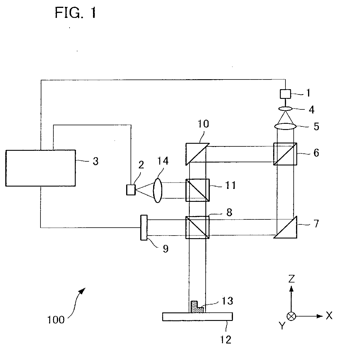
- FIG. 1 is a schematic diagram illustrating a measuring apparatus 100 according to the present embodiment.
- the measuring apparatus 100 includes a light source (first illumination device) 1, a light source (second illumination device) 2, a controlling/analyzing unit 3, a magnifying lens 4, collimator lenses 5 and 14, a beam splitter 6, mirrors 7 and 10, a beam multiplexer 8, a two-dimensional imaging element 9, and a beam guiding unit 11.
- the light source 1 is a coherent light source for interference measurement and the light source 2 is an incoherent light source (e.g., white LED) for non-interference measurement.
- the controlling/analyzing unit 3 can electrically control the lighting of the light source 1 and the light source 2 so as to switch the light source 1 or the light source 2 depending on interference measurement or non-interference measurement.
- the light source 1 for acquiring interference information in the present embodiment is a coherent wavelength-variable light source.
- the magnifying lens 4 magnifies a beam (first beam) illuminated (emitted) from the light source 1, and then the collimator lens 5 collimates the beam magnified by the magnifying lens 4 into a collimated beam in order to calculate the Z size (the position in the Z direction) of an object to be tested.
- the beam splitter 6 splits the beam collimated by the collimator lens 5 into a reference beam and a test beam.
- the reference beam is reflected by the mirror 7 and then transmits through the beam multiplexer 8 so as to be directed to the two-dimensional imaging element 9 serving as an optical detector.
- the test beam is reflected by the mirror 10 and then transmits through the beam guiding unit 11 for guiding light emitted from a non-interference light source.
- the transmitted test beam transmits through the beam multiplexer 8 and then is illuminated onto an object to be tested (test surface) 13 placed on a mounting platform 12.
- the beam splitter 6 is constituted independently of the beam multiplexer 8 on the optical path of the beam and constitutes a Mach-Zehnder interferometer. While, in the present embodiment, a description is given by taking an example of one two-dimensional imaging element 9, the two-dimensional imaging element 9 may also be used in plural: one used as an X-Y detector and the other one used as a Z detector.
- the test beam and the reference beam directed to the two-dimensional imaging element 9 cause an interference, so that interference fringes are formed by the resulting interference light on the two-dimensional imaging element 9.
- the controlling/analyzing unit 3 causes the two-dimensional imaging element 9 to capture a plurality of images of the interference fringes according to a change in wavelength.
- the controlling/analyzing unit 3 functions as a processing unit that performs calculation processing for calculating the shape (position (shape information) in the z direction) of the test surface of the object to be tested 13 by performing frequency analysis on the interference fringes of each image from the plurality of images (detection signals) captured by the two-dimensional imaging element 9.
- the controlling/analyzing unit 3 is constituted by a device including a CPU, a memory, an electrical circuit for performing various types of calculation.
- the optical path length difference L between the reference beam and the test beam is represented by the following Formula (1).
- the Z size is calculated by measuring the change in phase and analyzing it using Formula (1).
- the collimator lens 14 collimates the beam emitted from the light source 2 into a collimated beam (second beam) and then the beam collimated by the collimator lens 14 is guided to the beam guiding unit 11 in order to measure the X-Y projected size of the object to be tested 13.
- the beam guided to the beam guiding unit 11 transmits through the beam multiplexer 8 and then is illuminated onto the object to be tested 13 placed on the mounting platform 12.
- the beam reflected from the object to be tested 13 is further reflected by the beam multiplexer 8, so that the beam is incident on the two-dimensional imaging element 9 serving as a detector without transmitting through the beam splitter 6 and the beam guiding unit 11.
- the incident beam is captured by the two-dimensional imaging element 9.
- the controlling/analyzing unit 3 performs edge detection processing or the like for a light intensity image which is the obtained non-interference information so as to measure the X-Y projected size (shape information) of the object to be tested 13.
- the beam guiding unit 11 is disposed on the optical path between the mirror 10 and the beam multiplexer 8. However, it is sufficient that the beam guiding unit 11 is disposed on the optical path of test light for interference measurement between the beam splitter 6 and the beam multiplexer 8. For example, as shown in FIG. 2 , the beam guiding unit 11 may also be disposed on the optical path between the beam multiplexer 8 and the two-dimensional imaging element 9. When the light source 1 for interference measurement and the light source 2 for non-interference measurement have different wavelengths, the beam guiding unit 11 may also use a wavelength filter having properties of transmittance and reflectance which are different for each wavelength.
- the test beam emitted from the light source 1 is reflected by the mirror 10 and then transmits through the beam multiplexer 8 so as to be illuminated onto the object to be tested 13 placed on the mounting platform 12 without transmitting through the beam guiding unit 11 in order to calculate the Z size of the object to be tested 13. Then, the test beam reflected from the object to be tested 13 returns to the beam multiplexer 8 again, is further reflected by the beam multiplexer 8, and then transmits through the beam guiding unit 11 so as to be directed to the two-dimensional imaging element 9.
- the reference beam emitted from the light source 1 is reflected by the mirror 7, transmits through the beam multiplexer 8, and then transmits through the beam guiding unit 11 so as to be directed to the two-dimensional imaging element 9.
- the beam emitted from the light source 2 is firstly guided to the beam guiding unit 11 in order to measure the X-Y projected size of the object to be tested 13.
- the beam guided to the beam guiding unit 11 is reflected by the beam multiplexer 8 and then is illuminated onto the object to be tested 13 placed on the mounting platform 12. Then, the beam reflected from the object to be tested 13 is further reflected by the beam multiplexer 8, so that the beam is directed to the two-dimensional imaging element 9 by transmitting through the beam guiding unit 11.
- interference measurement is performed by a frequency scanning interferometer using a coherent wavelength-variable light source.
- a coherent wavelength-variable light source such as a white LED
- a stage 12 is adapted to be drivable in the Z direction
- interference measurement such as white interference measurement or the like may also be performed by using a known measuring unit.
- FIG. 4 is a diagram illustrating an exemplary configuration of the conventional Michelson interferometer.
- the beam emitted from a light source 301 for interference measurement is reflected by a beam splitter 302, is split into reference light and test light by a beam splitter 303, and then passes through a beam splitter 304 for guiding light emitted from a light source 308 for non-interference measurement so as to be incident on the object to be tested 306 placed on the mounting platform 12.
- the beam reflected from the object to be tested 306 passes through the beam splitter 304, the beam splitter 303, and the beam splitter 302 again so as to be incident on a detector 307.
- the test beam emitted from the light source 301 for interference measurement needs to pass through the beam splitters six times in total.
- the test beam emitted from the light source 1 passes through the beam splitter 6, the beam guiding unit 11, and the beam multiplexer 8 so as to be illuminated onto the object to be tested 13. Then, the test beam reflected from the object to be tested 13 is reflected by the beam multiplexer 8 and then is directed to the two-dimensional imaging element 9.
- the beam emitted from the light source 1 passes through the beam splitters four times in total without passing through the beam splitter 6 and the beam guiding unit 11 again.
- the beam emitted from the light source 308 for non-interference measurement is reflected by the beam splitter 304 and then is illuminated onto the object to be tested 306. Then, the beam reflected from the object to be tested 306 passes through the beam splitter 304, the beam splitter 303, and the beam splitter 302 so as to be incident on the detector 307.
- the beam emitted from the light source 308 for non-interference measurement needs to pass through the beam splitters four times in total.
- the beam emitted from the light source 2 is reflected by the beam guiding unit 11 and then passes through the beam multiplexer 8 so as to be illuminated onto the object to be tested 13. Then, the beam reflected from the object to be tested 13 is reflected by the beam multiplexer 8 and then is directed to the two-dimensional imaging element 9.
- the beam emitted from the light source 2 passes through the beam splitters three times in total without passing through the beam splitter 6 and the beam guiding unit 11 again.
- the beam emitted from the light source 1 passes through the beam splitters in different sequences, the beam emitted from the light source 1 passes through the beam splitters four times in total and the beam emitted from the light source 2 also passes through the beam splitters four times in total.
- the measuring apparatus 100 can reduce a loss in the amount of light from the light source 1 and the light source 2 by reducing the number of times that a beam passes through beam splitters with a large loss in the amount of light.
- the controlling/analyzing unit 3 can electrically control the lighting of the light source 1 and the light source 2 so as to switch the light source 1 or the light source 2 at high speed without insertion/removal of a shutter, so that interference measurement and non-interference measurement can be performed in a short time.
- a measuring apparatus that measures an object to be tested in a short time with a minimal loss in the amount of light in the optical system may be provided.
- FIG. 3 is a diagram illustrating a configuration of a measuring apparatus 200 according to a second embodiment.
- the measuring apparatus 200 according to the present embodiment is different from the measuring apparatus 100 according to the first embodiment in that a light source (third illumination device) 17 serving as a light source which performs non-interference measurement by directly irradiating the object to be tested 13 with light is disposed on the object to be tested 13.
- the light source 17 may be a ring illumination source or the like.
- ring illumination darkfield illumination as a means for realizing high precision measurement.
- the measuring apparatus 200 of the present embodiment is provided with an illumination source (epi-illumination source) as shown in the first embodiment and a ring illumination source, so that the X-Y measurement can be realized with high precision without depending on the shape of the object to be tested 13.
- the epi-illumination source and the ring illumination source may also be controlled so as to be switched at high speed in order to select an optimum measuring condition depending on the object to be tested 13.
- the light source 17 is one or a plurality of incoherent light sources.
- a white LED may be used as the light source 17.
- the controlling/analyzing unit 3 can electrically control the lighting of the light source 17, so that the light source is switchable for each interference measurement and for each non-interference measurement by a different illuminating method.
- high-speed switching to non-interference measurement using a ring illumination may also be performed in addition to interference measurement of the first embodiment and non-interference measurement using an epi-illumination source.
- the beam emitted from the light source 17 is reflected from the object to be tested 13, is reflected by the beam multiplexer 8, and then is incident on the two-dimensional imaging element 9 serving as a detector without passing through the beam splitter 6 and the beam guiding unit 11.
- the incident beam is captured by the two-dimensional imaging element 9.
- the controlling/analyzing unit 3 performs edge detection processing or the like for a light intensity image which is the obtained non-interference information so as to measure the X-Y projected size of the object to be tested 13.
- the Z size of the object to be tested 13 is obtained by performing interference measurement as in the first embodiment. As described above, the size of the object to be tested in three dimensions along X, Y, and Z axes can be acquired by interference measurement and non-interference measurement.
- the measuring apparatus 200 can reduce a loss in the amount of light because the number of times that a beam passes through beam splitters is less than that in the conventional technique.
- a measuring apparatus that measures the shape of a test surface at high speed with a minimal loss in the amount of light in the optical system, i.e., with a high efficiency of the amount of light in the optical system may be provided.
- a measuring apparatus that is capable of performing non-interference measurement using an epi-illumination source and high-speed switching to non-interference measurement using a different illuminating method may also be provided.
Landscapes
- Physics & Mathematics (AREA)
- General Physics & Mathematics (AREA)
- Length Measuring Devices By Optical Means (AREA)
- Instruments For Measurement Of Length By Optical Means (AREA)
- Engineering & Computer Science (AREA)
- Signal Processing (AREA)
Abstract
Description
- The present invention relates to a measuring apparatus that measures an object to be tested using interferometric data and non-interferometric data.
- Conventionally, there has been known an apparatus that measures the shape of an object to be tested based on non-interference information obtained by non-interference measurement and interference information obtained by interference measurement. Japanese Patent Laid-Open No.
H11-108625 - In addition, Japanese Patent Laid-Open No.
2009-536326 - However, in the apparatus disclosed in Japanese Patent Laid-Open No.
H11-108625 2009-536326 2009-536326 - Likewise, light emitted from the light source for non-interference measurement needs to pass through the third beam splitter for introducing a beam emitted from the light source for non-interference measurement, the second beam splitter for splitting and coupling the beam upon interference measurement into test light and reference light, and the first beam splitter for introducing a beam emitted from the light source for interference measurement until the light reaches the detector, resulting in a reduction in the amount of light. Thus, the amount of light received by the detector is small for measuring a black object to be tested having a low reflectance or for measuring a rough surface on which a test beam is scattered, resulting in a loss in the amount of light in the optical system.
- The present invention provides, for example, a measuring apparatus that measures an object to be tested in a short time with a minimal loss in the amount of light in the optical system.
- The present invention in its first aspect provides a measuring apparatus as specified in
claims 1 to 3. The present invention in its second aspect provides an measuring method as specified inclaim 4. - Further features of the present invention will become apparent from the following description of exemplary embodiments with reference to the attached drawings.
-
-
FIG. 1 is a schematic diagram illustrating a measuring apparatus according to a first embodiment. -
FIG. 2 is a schematic diagram illustrating the measuring apparatus according to the first embodiment with the position of a beam guiding unit changed. -
FIG. 3 is a schematic diagram illustrating a measuring apparatus according to a second embodiment. -
FIG. 4 is a schematic diagram illustrating the conventional measuring apparatus. - Hereinafter, preferred embodiments of the present invention will be described with reference to the drawings.
-
FIG. 1 is a schematic diagram illustrating ameasuring apparatus 100 according to the present embodiment. Themeasuring apparatus 100 includes a light source (first illumination device) 1, a light source (second illumination device) 2, a controlling/analyzingunit 3, amagnifying lens 4,collimator lenses beam splitter 6,mirrors beam multiplexer 8, a two-dimensional imaging element 9, and abeam guiding unit 11. - The
light source 1 is a coherent light source for interference measurement and thelight source 2 is an incoherent light source (e.g., white LED) for non-interference measurement. The controlling/analyzingunit 3 can electrically control the lighting of thelight source 1 and thelight source 2 so as to switch thelight source 1 or thelight source 2 depending on interference measurement or non-interference measurement. Thelight source 1 for acquiring interference information in the present embodiment is a coherent wavelength-variable light source. - Firstly, the
magnifying lens 4 magnifies a beam (first beam) illuminated (emitted) from thelight source 1, and then thecollimator lens 5 collimates the beam magnified by themagnifying lens 4 into a collimated beam in order to calculate the Z size (the position in the Z direction) of an object to be tested. Thebeam splitter 6 splits the beam collimated by thecollimator lens 5 into a reference beam and a test beam. - Firstly, the reference beam is reflected by the
mirror 7 and then transmits through thebeam multiplexer 8 so as to be directed to the two-dimensional imaging element 9 serving as an optical detector. On the other hand, the test beam is reflected by themirror 10 and then transmits through thebeam guiding unit 11 for guiding light emitted from a non-interference light source. The transmitted test beam transmits through thebeam multiplexer 8 and then is illuminated onto an object to be tested (test surface) 13 placed on amounting platform 12. Then, the test beam reflected from the object to be tested 13 returns to thebeam multiplexer 8 again, and then is further reflected by thebeam multiplexer 8, so that the test beam is directed to the two-dimensional imaging element 9 without transmitting through thebeam splitter 6 and thebeam guiding unit 11 again. Thebeam splitter 6 is constituted independently of thebeam multiplexer 8 on the optical path of the beam and constitutes a Mach-Zehnder interferometer. While, in the present embodiment, a description is given by taking an example of one two-dimensional imaging element 9, the two-dimensional imaging element 9 may also be used in plural: one used as an X-Y detector and the other one used as a Z detector. - The test beam and the reference beam directed to the two-
dimensional imaging element 9 cause an interference, so that interference fringes are formed by the resulting interference light on the two-dimensional imaging element 9. The controlling/analyzingunit 3 causes the two-dimensional imaging element 9 to capture a plurality of images of the interference fringes according to a change in wavelength. The controlling/analyzingunit 3 functions as a processing unit that performs calculation processing for calculating the shape (position (shape information) in the z direction) of the test surface of the object to be tested 13 by performing frequency analysis on the interference fringes of each image from the plurality of images (detection signals) captured by the two-dimensional imaging element 9. The controlling/analyzingunit 3 is constituted by a device including a CPU, a memory, an electrical circuit for performing various types of calculation. - Given that the total amount of scan of the frequency is ΔF, the speed of light is C, and the amount of change in phase of the interference signal is Δϕ, the optical path length difference L between the reference beam and the test beam is represented by the following Formula (1). The Z size is calculated by measuring the change in phase and analyzing it using Formula (1).
- Next, the
collimator lens 14 collimates the beam emitted from thelight source 2 into a collimated beam (second beam) and then the beam collimated by thecollimator lens 14 is guided to thebeam guiding unit 11 in order to measure the X-Y projected size of the object to be tested 13. Next, the beam guided to thebeam guiding unit 11 transmits through thebeam multiplexer 8 and then is illuminated onto the object to be tested 13 placed on themounting platform 12. After illumination, the beam reflected from the object to be tested 13 is further reflected by thebeam multiplexer 8, so that the beam is incident on the two-dimensional imaging element 9 serving as a detector without transmitting through thebeam splitter 6 and thebeam guiding unit 11. The incident beam is captured by the two-dimensional imaging element 9. Next, the controlling/analyzingunit 3 performs edge detection processing or the like for a light intensity image which is the obtained non-interference information so as to measure the X-Y projected size (shape information) of the object to be tested 13. - In the present embodiment, the
beam guiding unit 11 is disposed on the optical path between themirror 10 and thebeam multiplexer 8. However, it is sufficient that thebeam guiding unit 11 is disposed on the optical path of test light for interference measurement between thebeam splitter 6 and thebeam multiplexer 8. For example, as shown inFIG. 2 , thebeam guiding unit 11 may also be disposed on the optical path between thebeam multiplexer 8 and the two-dimensional imaging element 9. When thelight source 1 for interference measurement and thelight source 2 for non-interference measurement have different wavelengths, thebeam guiding unit 11 may also use a wavelength filter having properties of transmittance and reflectance which are different for each wavelength. - In
FIG. 2 , the test beam emitted from thelight source 1 is reflected by themirror 10 and then transmits through thebeam multiplexer 8 so as to be illuminated onto the object to be tested 13 placed on themounting platform 12 without transmitting through thebeam guiding unit 11 in order to calculate the Z size of the object to be tested 13. Then, the test beam reflected from the object to be tested 13 returns to thebeam multiplexer 8 again, is further reflected by thebeam multiplexer 8, and then transmits through thebeam guiding unit 11 so as to be directed to the two-dimensional imaging element 9. On the other hand, the reference beam emitted from thelight source 1 is reflected by themirror 7, transmits through thebeam multiplexer 8, and then transmits through thebeam guiding unit 11 so as to be directed to the two-dimensional imaging element 9. - In
FIG. 2 , the beam emitted from thelight source 2 is firstly guided to thebeam guiding unit 11 in order to measure the X-Y projected size of the object to be tested 13. The beam guided to thebeam guiding unit 11 is reflected by thebeam multiplexer 8 and then is illuminated onto the object to be tested 13 placed on the mountingplatform 12. Then, the beam reflected from the object to be tested 13 is further reflected by thebeam multiplexer 8, so that the beam is directed to the two-dimensional imaging element 9 by transmitting through thebeam guiding unit 11. - As described above, the size of the object to be tested in three dimensions along X, Y, and Z axes can be acquired by interference measurement and non-interference measurement. In the present embodiment, interference measurement is performed by a frequency scanning interferometer using a coherent wavelength-variable light source. However, the present invention is not limited thereto. When a low coherent light source such as a white LED is used as the
light source 1 for interference measurement and astage 12 is adapted to be drivable in the Z direction, interference measurement such as white interference measurement or the like may also be performed by using a known measuring unit. - Here, a comparison is made between the present embodiment and the conventional technique.
FIG. 4 is a diagram illustrating an exemplary configuration of the conventional Michelson interferometer. Upon measurement of the Z size of an object to be tested 306, the beam emitted from alight source 301 for interference measurement is reflected by abeam splitter 302, is split into reference light and test light by abeam splitter 303, and then passes through abeam splitter 304 for guiding light emitted from alight source 308 for non-interference measurement so as to be incident on the object to be tested 306 placed on the mountingplatform 12. Then, the beam reflected from the object to be tested 306 passes through thebeam splitter 304, thebeam splitter 303, and thebeam splitter 302 again so as to be incident on adetector 307. Thus, the test beam emitted from thelight source 301 for interference measurement needs to pass through the beam splitters six times in total. - In contrast, in the present embodiment, the test beam emitted from the
light source 1 passes through thebeam splitter 6, thebeam guiding unit 11, and thebeam multiplexer 8 so as to be illuminated onto the object to be tested 13. Then, the test beam reflected from the object to be tested 13 is reflected by thebeam multiplexer 8 and then is directed to the two-dimensional imaging element 9. Thus, the beam emitted from thelight source 1 passes through the beam splitters four times in total without passing through thebeam splitter 6 and thebeam guiding unit 11 again. - Likewise, in the configuration of a measuring
apparatus 300 shown inFIG. 4 upon X-Y measurement, the beam emitted from thelight source 308 for non-interference measurement is reflected by thebeam splitter 304 and then is illuminated onto the object to be tested 306. Then, the beam reflected from the object to be tested 306 passes through thebeam splitter 304, thebeam splitter 303, and thebeam splitter 302 so as to be incident on thedetector 307. Thus, the beam emitted from thelight source 308 for non-interference measurement needs to pass through the beam splitters four times in total. - In contrast, in the present embodiment, the beam emitted from the
light source 2 is reflected by thebeam guiding unit 11 and then passes through thebeam multiplexer 8 so as to be illuminated onto the object to be tested 13. Then, the beam reflected from the object to be tested 13 is reflected by thebeam multiplexer 8 and then is directed to the two-dimensional imaging element 9. Thus, the beam emitted from thelight source 2 passes through the beam splitters three times in total without passing through thebeam splitter 6 and thebeam guiding unit 11 again. - Also in the measuring
apparatus 100 shown inFIG. 2 , although the beam emitted from thelight source 1 passes through the beam splitters in different sequences, the beam emitted from thelight source 1 passes through the beam splitters four times in total and the beam emitted from thelight source 2 also passes through the beam splitters four times in total. - Thus, the measuring
apparatus 100 can reduce a loss in the amount of light from thelight source 1 and thelight source 2 by reducing the number of times that a beam passes through beam splitters with a large loss in the amount of light. In addition, in the measuringapparatus 100, the controlling/analyzingunit 3 can electrically control the lighting of thelight source 1 and thelight source 2 so as to switch thelight source 1 or thelight source 2 at high speed without insertion/removal of a shutter, so that interference measurement and non-interference measurement can be performed in a short time. - With the above configuration, according to the present embodiment, a measuring apparatus that measures an object to be tested in a short time with a minimal loss in the amount of light in the optical system may be provided.
-
FIG. 3 is a diagram illustrating a configuration of a measuring apparatus 200 according to a second embodiment. The measuring apparatus 200 according to the present embodiment is different from the measuringapparatus 100 according to the first embodiment in that a light source (third illumination device) 17 serving as a light source which performs non-interference measurement by directly irradiating the object to be tested 13 with light is disposed on the object to be tested 13. Thelight source 17 may be a ring illumination source or the like. In the X-Y measurement by reflective illumination, there is a known technique such as ring illumination, darkfield illumination as a means for realizing high precision measurement. The measuring apparatus 200 of the present embodiment is provided with an illumination source (epi-illumination source) as shown in the first embodiment and a ring illumination source, so that the X-Y measurement can be realized with high precision without depending on the shape of the object to be tested 13. The epi-illumination source and the ring illumination source may also be controlled so as to be switched at high speed in order to select an optimum measuring condition depending on the object to be tested 13. - The
light source 17 is one or a plurality of incoherent light sources. For example, a white LED may be used as thelight source 17. As in thelight source 1 and thelight source 2, the controlling/analyzingunit 3 can electrically control the lighting of thelight source 17, so that the light source is switchable for each interference measurement and for each non-interference measurement by a different illuminating method. Thus, high-speed switching to non-interference measurement using a ring illumination may also be performed in addition to interference measurement of the first embodiment and non-interference measurement using an epi-illumination source. - A description will be given of the X-Y measurement performed when the
light source 17 is used. Firstly, the beam emitted from thelight source 17 is reflected from the object to be tested 13, is reflected by thebeam multiplexer 8, and then is incident on the two-dimensional imaging element 9 serving as a detector without passing through thebeam splitter 6 and thebeam guiding unit 11. - The incident beam is captured by the two-
dimensional imaging element 9. As in the first embodiment, the controlling/analyzingunit 3 performs edge detection processing or the like for a light intensity image which is the obtained non-interference information so as to measure the X-Y projected size of the object to be tested 13. Next, the Z size of the object to be tested 13 is obtained by performing interference measurement as in the first embodiment. As described above, the size of the object to be tested in three dimensions along X, Y, and Z axes can be acquired by interference measurement and non-interference measurement. - As in the first embodiment, the measuring apparatus 200 can reduce a loss in the amount of light because the number of times that a beam passes through beam splitters is less than that in the conventional technique. Thus, also in the present embodiment, a measuring apparatus that measures the shape of a test surface at high speed with a minimal loss in the amount of light in the optical system, i.e., with a high efficiency of the amount of light in the optical system may be provided. A measuring apparatus that is capable of performing non-interference measurement using an epi-illumination source and high-speed switching to non-interference measurement using a different illuminating method may also be provided.
- While the present invention has been described with reference to exemplary embodiments, it is to be understood that the invention is not limited to the disclosed exemplary embodiments. The scope of the following claims is to be accorded the broadest interpretation so as to encompass all such modifications and equivalent structures and functions.
Claims (4)
- A measuring apparatus comprising (100):a first illumination device(1) configured to emit a first beam;a beam splitter(6) configured to split the first beam into test light and reference light;a beam multiplexer (8) configured to multiplex the test light reflected by an object to be tested (13) and the reference light;a second illumination device (2) configured to emit a second beam;a detector (9) configured to detect the second beam reflected by the object to be tested (13) and interference light between the test light and the reference light;a processing unit (3) configured to calculate shape information about the object to be tested (13) using a detection signal of light detected by the detector (9); anda beam guiding unit (11) configured to guide the second beam to the object to be tested (13),wherein the beam splitter (6) and the beam multiplexer (8) are separately provided, and the beam guiding unit (11) is disposed on an optical path of the test light between the beam splitter (6) and the beam multiplexer (8) or between the beam multiplexer (8) and the detector (9).
- The measuring apparatus according to claim 1, further comprising:a third illumination device configured to directly irradiate the object to be tested with light without the intermediary of the beam guiding unit.
- The measuring apparatus according to claim 1, wherein the beam guiding unit is a wavelength filter disposed on the optical path of the test light between the beam splitter and the beam multiplexer.
- A measuring method comprising:a step of emitting a first beam;a step of splitting the first beam into test light and reference light;a step of multiplexing the test light reflected by an object to be tested and the reference light;a step of emitting a second beam;a step of detecting the second beam reflected by the object to be tested and interference light between the test light and the reference light; anda step of calculating shape information about the object to be tested using a detected signal of light,wherein, the second beam is guided to the optical path and thereby to the object to be tested ,on an optical path of the test light after being split and before being multiplexed or on the optical path after the test light and the reference light have been multiplexed and before the interference light has been detected.
Applications Claiming Priority (1)
| Application Number | Priority Date | Filing Date | Title |
|---|---|---|---|
| JP2013173381A JP2015040825A (en) | 2013-08-23 | 2013-08-23 | Measuring device |
Publications (1)
| Publication Number | Publication Date |
|---|---|
| EP2840352A1 true EP2840352A1 (en) | 2015-02-25 |
Family
ID=51389858
Family Applications (1)
| Application Number | Title | Priority Date | Filing Date |
|---|---|---|---|
| EP14002894.5A Withdrawn EP2840352A1 (en) | 2013-08-23 | 2014-08-20 | Interferometric apparatus combined with a non interferometric apparatus, and measuring method |
Country Status (3)
| Country | Link |
|---|---|
| US (1) | US20150057972A1 (en) |
| EP (1) | EP2840352A1 (en) |
| JP (1) | JP2015040825A (en) |
Families Citing this family (3)
| Publication number | Priority date | Publication date | Assignee | Title |
|---|---|---|---|---|
| KR101855816B1 (en) * | 2016-05-13 | 2018-05-10 | 주식회사 고영테크놀러지 | Biological Tissue Inspection Apparatus and Method thereof |
| CN111536883B (en) * | 2020-06-10 | 2021-07-23 | 中北大学 | A micro-displacement sensor based on composite grating |
| CN113932728A (en) * | 2020-06-29 | 2022-01-14 | 深圳中科飞测科技股份有限公司 | Detection equipment and detection method |
Citations (4)
| Publication number | Priority date | Publication date | Assignee | Title |
|---|---|---|---|---|
| JPH11108625A (en) | 1997-10-06 | 1999-04-23 | Canon Inc | Surface shape measuring device |
| US6496267B1 (en) * | 1999-04-05 | 2002-12-17 | Olympus Optical Co., Ltd. | Scanning microscope |
| US20060132799A1 (en) * | 2001-06-29 | 2006-06-22 | Franck Dubois | Digital holographic microscope |
| US20090059208A1 (en) * | 2006-05-08 | 2009-03-05 | Norbert Steffens | Apparatus and method for a combined interferometric and image based geometric determination, particularly in the microsystem technology |
-
2013
- 2013-08-23 JP JP2013173381A patent/JP2015040825A/en active Pending
-
2014
- 2014-08-20 EP EP14002894.5A patent/EP2840352A1/en not_active Withdrawn
- 2014-08-21 US US14/464,742 patent/US20150057972A1/en not_active Abandoned
Patent Citations (5)
| Publication number | Priority date | Publication date | Assignee | Title |
|---|---|---|---|---|
| JPH11108625A (en) | 1997-10-06 | 1999-04-23 | Canon Inc | Surface shape measuring device |
| US6496267B1 (en) * | 1999-04-05 | 2002-12-17 | Olympus Optical Co., Ltd. | Scanning microscope |
| US20060132799A1 (en) * | 2001-06-29 | 2006-06-22 | Franck Dubois | Digital holographic microscope |
| US20090059208A1 (en) * | 2006-05-08 | 2009-03-05 | Norbert Steffens | Apparatus and method for a combined interferometric and image based geometric determination, particularly in the microsystem technology |
| JP2009536326A (en) | 2006-05-08 | 2009-10-08 | カール マール ホールディング ゲーエムベーハー | Apparatus and method for combined interference and image based shape determination, especially in microsystems |
Also Published As
| Publication number | Publication date |
|---|---|
| JP2015040825A (en) | 2015-03-02 |
| US20150057972A1 (en) | 2015-02-26 |
Similar Documents
| Publication | Publication Date | Title |
|---|---|---|
| KR102456213B1 (en) | Systems and Methods for Focus Optimization for Imaging-Based Overlay Metrology | |
| KR101750188B1 (en) | Confocal measurement device | |
| JP6247752B2 (en) | Optical measuring apparatus and optical measuring method for obtaining distance difference | |
| TWI756306B (en) | Optical characteristic measuring apparatus and optical characteristic measuring method | |
| EP1939581A1 (en) | Apparatus for the contact-less, interferometric determination of surface height profiles and depth scattering profiles | |
| US8767218B2 (en) | Optical apparatus for non-contact measurement or testing of a body surface | |
| CN107037437B (en) | Thickness measuring device and thickness measuring method | |
| KR101941581B1 (en) | Apparatus for optically measuring distance | |
| WO2013091584A1 (en) | Method and device for detecting defects in substrate | |
| US20200363187A1 (en) | Light sensor and coordinate measuring machine | |
| JP4090860B2 (en) | 3D shape measuring device | |
| KR101794641B1 (en) | A slope spectrum system for measuring height of object by using wavelength division | |
| KR101251292B1 (en) | Three dimensional shape and depth measuring device using polarized light | |
| RU2018114296A (en) | DEVICE FOR MEASURING PARAMETERS OF PHASE ELEMENTS AND DISPERSION OF OPTICAL FIBER AND METHOD FOR MEASURING PARAMETERS OF PHASE ELEMENTS AND DISPERSION OF OPTICAL FIBER | |
| KR101356706B1 (en) | Structured illumination microscope based on intensity modulation and scanning system | |
| US20050274913A1 (en) | Object data input apparatus and object reconstruction apparatus | |
| EP2840352A1 (en) | Interferometric apparatus combined with a non interferometric apparatus, and measuring method | |
| US7576864B2 (en) | Interferometric measuring device for recording geometric data for surfaces | |
| EP2634558A2 (en) | Shape measurement device and shape measurement method | |
| KR20240161192A (en) | Inspection device | |
| JP2016102776A (en) | Inspection device and method for inspection | |
| US10627346B2 (en) | Refractive index measuring device and refractive index measuring method | |
| GB2433317A (en) | Phase shifting imaging module for handheld interferometer | |
| KR102786771B1 (en) | Inspection apparatus for displacement measurement and visual acquisition at the same time | |
| US8493568B2 (en) | Optical imaging apparatus and method |
Legal Events
| Date | Code | Title | Description |
|---|---|---|---|
| PUAI | Public reference made under article 153(3) epc to a published international application that has entered the european phase |
Free format text: ORIGINAL CODE: 0009012 |
|
| 17P | Request for examination filed |
Effective date: 20140820 |
|
| AK | Designated contracting states |
Kind code of ref document: A1 Designated state(s): AL AT BE BG CH CY CZ DE DK EE ES FI FR GB GR HR HU IE IS IT LI LT LU LV MC MK MT NL NO PL PT RO RS SE SI SK SM TR |
|
| AX | Request for extension of the european patent |
Extension state: BA ME |
|
| R17P | Request for examination filed (corrected) |
Effective date: 20150825 |
|
| RBV | Designated contracting states (corrected) |
Designated state(s): AL AT BE BG CH CY CZ DE DK EE ES FI FR GB GR HR HU IE IS IT LI LT LU LV MC MK MT NL NO PL PT RO RS SE SI SK SM TR |
|
| RIC1 | Information provided on ipc code assigned before grant |
Ipc: G01B 9/02 20060101ALI20180625BHEP Ipc: G01B 11/24 20060101ALI20180625BHEP Ipc: G01B 11/02 20060101AFI20180625BHEP |
|
| GRAP | Despatch of communication of intention to grant a patent |
Free format text: ORIGINAL CODE: EPIDOSNIGR1 |
|
| INTG | Intention to grant announced |
Effective date: 20180820 |
|
| STAA | Information on the status of an ep patent application or granted ep patent |
Free format text: STATUS: THE APPLICATION IS DEEMED TO BE WITHDRAWN |
|
| 18D | Application deemed to be withdrawn |
Effective date: 20190103 |