EP2840276A2 - Clutch learning apparatus - Google Patents
Clutch learning apparatus Download PDFInfo
- Publication number
- EP2840276A2 EP2840276A2 EP14178095.7A EP14178095A EP2840276A2 EP 2840276 A2 EP2840276 A2 EP 2840276A2 EP 14178095 A EP14178095 A EP 14178095A EP 2840276 A2 EP2840276 A2 EP 2840276A2
- Authority
- EP
- European Patent Office
- Prior art keywords
- clutch
- gear
- torque
- state
- input shaft
- Prior art date
- Legal status (The legal status is an assumption and is not a legal conclusion. Google has not performed a legal analysis and makes no representation as to the accuracy of the status listed.)
- Granted
Links
- 230000005540 biological transmission Effects 0.000 claims abstract description 116
- 230000007246 mechanism Effects 0.000 claims abstract description 40
- 230000008859 change Effects 0.000 claims abstract description 20
- 238000003860 storage Methods 0.000 claims abstract description 13
- 238000002485 combustion reaction Methods 0.000 description 33
- 239000012530 fluid Substances 0.000 description 16
- 230000007935 neutral effect Effects 0.000 description 11
- 230000007423 decrease Effects 0.000 description 9
- 238000010586 diagram Methods 0.000 description 4
- 230000000694 effects Effects 0.000 description 4
- 230000006870 function Effects 0.000 description 4
- 238000000034 method Methods 0.000 description 4
- 230000004048 modification Effects 0.000 description 4
- 238000012986 modification Methods 0.000 description 4
- 230000001133 acceleration Effects 0.000 description 3
- 238000005520 cutting process Methods 0.000 description 3
- 230000002093 peripheral effect Effects 0.000 description 3
- 238000003825 pressing Methods 0.000 description 3
- 230000003247 decreasing effect Effects 0.000 description 2
- 238000010248 power generation Methods 0.000 description 2
- 230000004044 response Effects 0.000 description 2
- 239000007858 starting material Substances 0.000 description 2
- 230000002730 additional effect Effects 0.000 description 1
- 230000004075 alteration Effects 0.000 description 1
- 230000015556 catabolic process Effects 0.000 description 1
- 210000000078 claw Anatomy 0.000 description 1
- 230000000295 complement effect Effects 0.000 description 1
- 238000006731 degradation reaction Methods 0.000 description 1
- 238000001514 detection method Methods 0.000 description 1
- 238000006073 displacement reaction Methods 0.000 description 1
- 238000002360 preparation method Methods 0.000 description 1
- 230000002265 prevention Effects 0.000 description 1
- 230000008569 process Effects 0.000 description 1
- 230000009467 reduction Effects 0.000 description 1
- 230000001105 regulatory effect Effects 0.000 description 1
- 238000004904 shortening Methods 0.000 description 1
- 238000006467 substitution reaction Methods 0.000 description 1
- 230000001629 suppression Effects 0.000 description 1
Images



Classifications
-
- F—MECHANICAL ENGINEERING; LIGHTING; HEATING; WEAPONS; BLASTING
- F16—ENGINEERING ELEMENTS AND UNITS; GENERAL MEASURES FOR PRODUCING AND MAINTAINING EFFECTIVE FUNCTIONING OF MACHINES OR INSTALLATIONS; THERMAL INSULATION IN GENERAL
- F16H—GEARING
- F16H63/00—Control outputs from the control unit to change-speed- or reversing-gearings for conveying rotary motion or to other devices than the final output mechanism
- F16H63/40—Control outputs from the control unit to change-speed- or reversing-gearings for conveying rotary motion or to other devices than the final output mechanism comprising signals other than signals for actuating the final output mechanisms
-
- F—MECHANICAL ENGINEERING; LIGHTING; HEATING; WEAPONS; BLASTING
- F16—ENGINEERING ELEMENTS AND UNITS; GENERAL MEASURES FOR PRODUCING AND MAINTAINING EFFECTIVE FUNCTIONING OF MACHINES OR INSTALLATIONS; THERMAL INSULATION IN GENERAL
- F16D—COUPLINGS FOR TRANSMITTING ROTATION; CLUTCHES; BRAKES
- F16D48/00—External control of clutches
- F16D48/06—Control by electric or electronic means, e.g. of fluid pressure
-
- F—MECHANICAL ENGINEERING; LIGHTING; HEATING; WEAPONS; BLASTING
- F16—ENGINEERING ELEMENTS AND UNITS; GENERAL MEASURES FOR PRODUCING AND MAINTAINING EFFECTIVE FUNCTIONING OF MACHINES OR INSTALLATIONS; THERMAL INSULATION IN GENERAL
- F16H—GEARING
- F16H61/00—Control functions within control units of change-speed- or reversing-gearings for conveying rotary motion ; Control of exclusively fluid gearing, friction gearing, gearings with endless flexible members or other particular types of gearing
- F16H61/26—Generation or transmission of movements for final actuating mechanisms
- F16H61/28—Generation or transmission of movements for final actuating mechanisms with at least one movement of the final actuating mechanism being caused by a non-mechanical force, e.g. power-assisted
-
- F—MECHANICAL ENGINEERING; LIGHTING; HEATING; WEAPONS; BLASTING
- F16—ENGINEERING ELEMENTS AND UNITS; GENERAL MEASURES FOR PRODUCING AND MAINTAINING EFFECTIVE FUNCTIONING OF MACHINES OR INSTALLATIONS; THERMAL INSULATION IN GENERAL
- F16D—COUPLINGS FOR TRANSMITTING ROTATION; CLUTCHES; BRAKES
- F16D2500/00—External control of clutches by electric or electronic means
- F16D2500/10—System to be controlled
- F16D2500/104—Clutch
- F16D2500/10406—Clutch position
- F16D2500/10412—Transmission line of a vehicle
-
- F—MECHANICAL ENGINEERING; LIGHTING; HEATING; WEAPONS; BLASTING
- F16—ENGINEERING ELEMENTS AND UNITS; GENERAL MEASURES FOR PRODUCING AND MAINTAINING EFFECTIVE FUNCTIONING OF MACHINES OR INSTALLATIONS; THERMAL INSULATION IN GENERAL
- F16D—COUPLINGS FOR TRANSMITTING ROTATION; CLUTCHES; BRAKES
- F16D2500/00—External control of clutches by electric or electronic means
- F16D2500/10—System to be controlled
- F16D2500/104—Clutch
- F16D2500/10443—Clutch type
- F16D2500/10462—Dog-type clutch
-
- F—MECHANICAL ENGINEERING; LIGHTING; HEATING; WEAPONS; BLASTING
- F16—ENGINEERING ELEMENTS AND UNITS; GENERAL MEASURES FOR PRODUCING AND MAINTAINING EFFECTIVE FUNCTIONING OF MACHINES OR INSTALLATIONS; THERMAL INSULATION IN GENERAL
- F16D—COUPLINGS FOR TRANSMITTING ROTATION; CLUTCHES; BRAKES
- F16D2500/00—External control of clutches by electric or electronic means
- F16D2500/10—System to be controlled
- F16D2500/108—Gear
- F16D2500/1081—Actuation type
- F16D2500/1085—Automatic transmission
-
- F—MECHANICAL ENGINEERING; LIGHTING; HEATING; WEAPONS; BLASTING
- F16—ENGINEERING ELEMENTS AND UNITS; GENERAL MEASURES FOR PRODUCING AND MAINTAINING EFFECTIVE FUNCTIONING OF MACHINES OR INSTALLATIONS; THERMAL INSULATION IN GENERAL
- F16D—COUPLINGS FOR TRANSMITTING ROTATION; CLUTCHES; BRAKES
- F16D2500/00—External control of clutches by electric or electronic means
- F16D2500/30—Signal inputs
- F16D2500/302—Signal inputs from the actuator
- F16D2500/3026—Stroke
-
- F—MECHANICAL ENGINEERING; LIGHTING; HEATING; WEAPONS; BLASTING
- F16—ENGINEERING ELEMENTS AND UNITS; GENERAL MEASURES FOR PRODUCING AND MAINTAINING EFFECTIVE FUNCTIONING OF MACHINES OR INSTALLATIONS; THERMAL INSULATION IN GENERAL
- F16D—COUPLINGS FOR TRANSMITTING ROTATION; CLUTCHES; BRAKES
- F16D2500/00—External control of clutches by electric or electronic means
- F16D2500/30—Signal inputs
- F16D2500/304—Signal inputs from the clutch
- F16D2500/3041—Signal inputs from the clutch from the input shaft
- F16D2500/30415—Speed of the input shaft
-
- F—MECHANICAL ENGINEERING; LIGHTING; HEATING; WEAPONS; BLASTING
- F16—ENGINEERING ELEMENTS AND UNITS; GENERAL MEASURES FOR PRODUCING AND MAINTAINING EFFECTIVE FUNCTIONING OF MACHINES OR INSTALLATIONS; THERMAL INSULATION IN GENERAL
- F16D—COUPLINGS FOR TRANSMITTING ROTATION; CLUTCHES; BRAKES
- F16D2500/00—External control of clutches by electric or electronic means
- F16D2500/30—Signal inputs
- F16D2500/304—Signal inputs from the clutch
- F16D2500/3041—Signal inputs from the clutch from the input shaft
- F16D2500/30415—Speed of the input shaft
- F16D2500/30417—Speed change rate of the input shaft
-
- F—MECHANICAL ENGINEERING; LIGHTING; HEATING; WEAPONS; BLASTING
- F16—ENGINEERING ELEMENTS AND UNITS; GENERAL MEASURES FOR PRODUCING AND MAINTAINING EFFECTIVE FUNCTIONING OF MACHINES OR INSTALLATIONS; THERMAL INSULATION IN GENERAL
- F16D—COUPLINGS FOR TRANSMITTING ROTATION; CLUTCHES; BRAKES
- F16D2500/00—External control of clutches by electric or electronic means
- F16D2500/30—Signal inputs
- F16D2500/304—Signal inputs from the clutch
- F16D2500/3042—Signal inputs from the clutch from the output shaft
- F16D2500/30421—Torque of the output shaft
-
- F—MECHANICAL ENGINEERING; LIGHTING; HEATING; WEAPONS; BLASTING
- F16—ENGINEERING ELEMENTS AND UNITS; GENERAL MEASURES FOR PRODUCING AND MAINTAINING EFFECTIVE FUNCTIONING OF MACHINES OR INSTALLATIONS; THERMAL INSULATION IN GENERAL
- F16D—COUPLINGS FOR TRANSMITTING ROTATION; CLUTCHES; BRAKES
- F16D2500/00—External control of clutches by electric or electronic means
- F16D2500/30—Signal inputs
- F16D2500/308—Signal inputs from the transmission
- F16D2500/30806—Engaged transmission ratio
-
- F—MECHANICAL ENGINEERING; LIGHTING; HEATING; WEAPONS; BLASTING
- F16—ENGINEERING ELEMENTS AND UNITS; GENERAL MEASURES FOR PRODUCING AND MAINTAINING EFFECTIVE FUNCTIONING OF MACHINES OR INSTALLATIONS; THERMAL INSULATION IN GENERAL
- F16D—COUPLINGS FOR TRANSMITTING ROTATION; CLUTCHES; BRAKES
- F16D2500/00—External control of clutches by electric or electronic means
- F16D2500/30—Signal inputs
- F16D2500/308—Signal inputs from the transmission
- F16D2500/3081—Signal inputs from the transmission from the input shaft
- F16D2500/30816—Speed of the input shaft
-
- F—MECHANICAL ENGINEERING; LIGHTING; HEATING; WEAPONS; BLASTING
- F16—ENGINEERING ELEMENTS AND UNITS; GENERAL MEASURES FOR PRODUCING AND MAINTAINING EFFECTIVE FUNCTIONING OF MACHINES OR INSTALLATIONS; THERMAL INSULATION IN GENERAL
- F16D—COUPLINGS FOR TRANSMITTING ROTATION; CLUTCHES; BRAKES
- F16D2500/00—External control of clutches by electric or electronic means
- F16D2500/30—Signal inputs
- F16D2500/308—Signal inputs from the transmission
- F16D2500/3082—Signal inputs from the transmission from the output shaft
- F16D2500/30825—Speed of the output shaft
-
- F—MECHANICAL ENGINEERING; LIGHTING; HEATING; WEAPONS; BLASTING
- F16—ENGINEERING ELEMENTS AND UNITS; GENERAL MEASURES FOR PRODUCING AND MAINTAINING EFFECTIVE FUNCTIONING OF MACHINES OR INSTALLATIONS; THERMAL INSULATION IN GENERAL
- F16D—COUPLINGS FOR TRANSMITTING ROTATION; CLUTCHES; BRAKES
- F16D2500/00—External control of clutches by electric or electronic means
- F16D2500/50—Problem to be solved by the control system
- F16D2500/502—Relating the clutch
- F16D2500/50245—Calibration or recalibration of the clutch touch-point
- F16D2500/50251—During operation
- F16D2500/5026—Gear engaged
-
- F—MECHANICAL ENGINEERING; LIGHTING; HEATING; WEAPONS; BLASTING
- F16—ENGINEERING ELEMENTS AND UNITS; GENERAL MEASURES FOR PRODUCING AND MAINTAINING EFFECTIVE FUNCTIONING OF MACHINES OR INSTALLATIONS; THERMAL INSULATION IN GENERAL
- F16D—COUPLINGS FOR TRANSMITTING ROTATION; CLUTCHES; BRAKES
- F16D2500/00—External control of clutches by electric or electronic means
- F16D2500/50—Problem to be solved by the control system
- F16D2500/506—Relating the transmission
- F16D2500/50607—Facilitating engagement of a dog clutches, e.g. preventing of gear butting
-
- F—MECHANICAL ENGINEERING; LIGHTING; HEATING; WEAPONS; BLASTING
- F16—ENGINEERING ELEMENTS AND UNITS; GENERAL MEASURES FOR PRODUCING AND MAINTAINING EFFECTIVE FUNCTIONING OF MACHINES OR INSTALLATIONS; THERMAL INSULATION IN GENERAL
- F16D—COUPLINGS FOR TRANSMITTING ROTATION; CLUTCHES; BRAKES
- F16D2500/00—External control of clutches by electric or electronic means
- F16D2500/70—Details about the implementation of the control system
- F16D2500/704—Output parameters from the control unit; Target parameters to be controlled
- F16D2500/70402—Actuator parameters
- F16D2500/70408—Torque
-
- F—MECHANICAL ENGINEERING; LIGHTING; HEATING; WEAPONS; BLASTING
- F16—ENGINEERING ELEMENTS AND UNITS; GENERAL MEASURES FOR PRODUCING AND MAINTAINING EFFECTIVE FUNCTIONING OF MACHINES OR INSTALLATIONS; THERMAL INSULATION IN GENERAL
- F16D—COUPLINGS FOR TRANSMITTING ROTATION; CLUTCHES; BRAKES
- F16D2500/00—External control of clutches by electric or electronic means
- F16D2500/70—Details about the implementation of the control system
- F16D2500/704—Output parameters from the control unit; Target parameters to be controlled
- F16D2500/70402—Actuator parameters
- F16D2500/7041—Position
-
- F—MECHANICAL ENGINEERING; LIGHTING; HEATING; WEAPONS; BLASTING
- F16—ENGINEERING ELEMENTS AND UNITS; GENERAL MEASURES FOR PRODUCING AND MAINTAINING EFFECTIVE FUNCTIONING OF MACHINES OR INSTALLATIONS; THERMAL INSULATION IN GENERAL
- F16D—COUPLINGS FOR TRANSMITTING ROTATION; CLUTCHES; BRAKES
- F16D2500/00—External control of clutches by electric or electronic means
- F16D2500/70—Details about the implementation of the control system
- F16D2500/704—Output parameters from the control unit; Target parameters to be controlled
- F16D2500/70422—Clutch parameters
- F16D2500/70438—From the output shaft
- F16D2500/7044—Output shaft torque
-
- F—MECHANICAL ENGINEERING; LIGHTING; HEATING; WEAPONS; BLASTING
- F16—ENGINEERING ELEMENTS AND UNITS; GENERAL MEASURES FOR PRODUCING AND MAINTAINING EFFECTIVE FUNCTIONING OF MACHINES OR INSTALLATIONS; THERMAL INSULATION IN GENERAL
- F16H—GEARING
- F16H2302/00—Determining the way or trajectory to new ratio, e.g. by determining speed, torque or time parameters for shift transition
Definitions
- An embodiment of this disclosure relates to a clutch learning apparatus that learns a position where a clutch mounted on a vehicle begins to be connected.
- a clutch that switches transmission/non-transmission of power is provided between an internal combustion engine and a gear shift mechanism of a vehicle.
- As the control states of the clutch there are three states of a connected state, a disconnected state, and a slip state where contact is made while slipping in an intermediate state therebetween. Since the clutch is brought into the slip state whenever the clutch is switched from the disconnected state to the connected state, the clutch wears out and becomes thin as its use proceeds. Incidentally, when the clutch is worn out, there is a case where the connection/disconnection operation of the clutch is not performed at an intended timing. For example, if the disconnection time of the clutch becomes long, the time period for which torque transmission to the gear shift mechanism side cannot be made becomes long correspondingly.
- JP 2012-86596A is an example of related art.
- a clutch learning apparatus includes a gear shift mechanism that has a plurality of gear pairs with different gear ratios between an input shaft and an output shaft and that switches between a torque transmission state where torque is transmitted and a torque non-transmission state where torque is not transmitted between the input shaft and the output shaft for each of the gear pairs; a clutch that is connected to the input shaft of the gear shift mechanism and changes a rotation transmission state of rotary power to be supplied from a driving source side; a control unit that controls the rotation transmission state of the clutch; and a storage unit that stores transmission information showing that the rotary power begins to be transmitted to the input shaft by the clutch.
- the control unit performs the clutch control of disconnecting the clutch after being temporarily brought into the rotation transmission state while the gear pair in the torque transmission state is changed to another gear pair with a different gear ratio in the gear shift mechanism.
- the storage unit stores the transmission information when a change in the rotation state of the input shaft side is a predetermined value or more due to the clutch control. According to this embodiment, since it is possible to execute shift change control frequently performed during driving of a vehicle, that is, to execute learning during the control that requires disconnection of the clutch, it is not necessary to separately provide a control period for the engagement starting point learning, and the engagement starting point learning can be easily performed.
- the shift change control is frequently performed during driving of a vehicle, the possibility that the engagement starting point learning is restricted in terms of execution timing is low, and the learning can be repeated multiple times. Moreover, since there is a chance to learn for every shift change control, it is possible to shorten learning intervals, and learning precision can be improved. Additionally, although the clutch is brought into a slip state for every start or every gear shift, and is apt to generate heat and expand thermally, since there is a chance of learning for every shift change control, the influence of the thermal expansion is easily reflected in the learning. As a result, not only learning frequency can be improved, but also the reliability of learning results can be improved.
- a motor that adjusts the output torque of the output shaft while the gear pair of the torque transmission state is changed to another gear pair with a different gear ratio may be connected to the output shaft.
- the output torque of the output shaft decreases, but the decrease of the output torque can be suppressed by complementing the torque with the motor.
- the storage unit may store new transmission information when the gear shift mechanism switches a gear pair in the torque transmission state from a gear pair with a high gear ratio to a gear pair with a low gear ratio.
- the gear shift mechanism switches a gear pair in the torque transmission state from a gear pair with a high gear ratio to a gear pair with a low gear ratio.
- the gear shift mechanism may be a dog transmission.
- the synchronization of the rotation speed of the internal combustion engine side and the rotation speed of the gear shift mechanism side becomes easy by performing the clutch control for the engagement starting point learning, while performing the engagement starting point learning of the clutch.
- the transmission information may be information on a position where the clutch begins to be connected.
- the transmission information may be information on an engagement starting point where the clutch begins to be connected.
- the engagement starting point may be stored during a shift operation of the gear shift mechanism in the torque non-transmission state.
- control unit may perform a double clutch control in which the gear shift mechanism is temporarily brought into the rotation transmission state after the clutch is disconnected from the rotation transmission state before gear shift of the gear shift mechanism, and the clutch is disconnected again.
- Fig. 1 is a functional block diagram of a hybrid vehicle including a clutch learning apparatus related to an embodiment.
- the clutch learning apparatus of the present embodiment executes the learning of a position where the clutch begins to be connected, in other words, the learning of a control position where rotary power begins to be transmitted, what is so called, an engagement starting point learning while a gear shift mechanism performs the shift of a gear, and enables the result of the learning to be reflected in various kinds of control.
- a hybrid vehicle 10 shown in Fig. 1 is constituted by an internal combustion engine 12, a clutch 14, an automatic transmission (an automated transmission) 16, a motor generator 18, an inverter 20, a battery 22, a differential device (differential gear) 24, a control unit 26, a storage unit 28, or the like.
- the configuration irrelevant to the present embodiment is omitted.
- the internal combustion engine 12 is, for example, a gasoline engine or the like, and engine speed or engine torque is controlled by the control of the control unit 26.
- the clutch 14 is arranged between an output shaft of the internal combustion engine 12 and an input shaft of the automatic transmission 16.
- the clutch 14 has three states of a connected state where the power (rotary power or rotary torque) supplied from an internal combustion engine 12 side is transmitted, a disconnected state where the power is not transmitted, and a slip state where contact is made while slipping in an intermediate state between the connected state and the disconnected state.
- a control state of the clutch 14 is also controlled by the control unit 26.
- the automatic transmission (gear shift mechanism) 16 can be a dog transmission including the so-called dog clutch to be described below, the automatic transmission may be transmissions equipped with a synchromesh in other examples.
- the motor generator 18 is connected to an output shaft side of the automatic transmission 16.
- a switching mechanism 30 is provided between the motor generator 18 and the output shaft of the automatic transmission 16. A case where the motor generator 18 is directly connected to the output shaft side of the automatic transmission 16 and a case where the motor generator 18 is separated from the output shaft side of the automatic transmission 16 can be selected by the switching mechanism 30.
- the motor generator 18 In the case where the motor generator 18 is directly connected to the output shaft side, it is possible to receive the power supplied via the inverter 20 from the battery 22 to provide the output torque of the motor generator 18 functioning as a motor to a differential device 24 side. Accordingly, in the case where the driving power supplied from the internal combustion engine 12 is not received, EV driving having only the motor generator 18 as a driving source is enabled. Additionally, in the case where the driving power supplied from the internal combustion engine 12 is received, assist driving that assists in the driving power of the internal combustion engine 12 is enabled. Additionally, it is possible to make the motor generator 18 function as a generator at the time of the braking of the hybrid vehicle 10 to charge the battery 22 via the inverter 20. In addition, if the motor generator 18 is separated from an automatic transmission 16 side by the switching mechanism 30, the engine driving with only the internal combustion engine 12 is enabled.
- the differential device 24 distributes and transmits the torque from a power source (the internal combustion engine 12, the motor generator 18, or both) to respective wheels 32 while absorbing the speed difference (difference between rotation speeds) caused in the inner and outer wheels 32 when the hybrid vehicle 10 turns.
- a power source the internal combustion engine 12, the motor generator 18, or both
- the control unit 26 performs a cooperation control of the internal combustion engine 12, the clutch 14, the automatic transmission 16, the inverter 20, the battery 22, or the like to realize optimal driving, according to a driving demand based on the driving operation of a driver or the driving state of the hybrid vehicle 10.
- the control unit 26 is shown as an integrated control unit that carries out integrated control of respective devices.
- the control unit may include individual control units for every controlled object, and the respective control units may perform cooperation control. Additionally, several functions may be put together and controlled.
- the storage unit 28 stores various kinds of information that the control unit 26 acquires. Additionally, the stored information is provided to the control unit 26, and is reflected in the feedback control of the respective devices.
- the control unit 26 may process information to create new information, or may cause the existing information to be updated and stored in the storage unit 28.
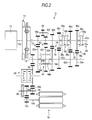
- Fig. 2 is a schematic view of a drive system centering on a drive train of the hybrid vehicle 10.
- the switching mechanism 30 of Fig. 1 is omitted and the motor generator 18 is directly connected to the differential device 24 is shown in the configuration of Fig. 2 .
- a dry clutch 14, for example, is arranged between an input shaft 16a of the automatic transmission 16 and a crankshaft 12a of the internal combustion engine 12. The detailed structure of the clutch 14 is shown in Fig. 3 .
- the clutch 14 has a flywheel 34, a clutch disk 36, a pressure plate 38, a diaphragm spring 40, a clutch cover 42, and a clutch control mechanism 44.
- the flywheel 34 is connected to the crankshaft 12a, and is integrally rotated with the crankshaft 12a.
- the clutch cover 42 is integrally rotatably attached to the flywheel 34.
- the clutch disk 36 is attached to the input shaft 16a of the automatic transmission 16 by spline fitting.
- the clutch disk 36 is relatively movable in an axial direction and relatively non-rotatable with respect to the input shaft 16a.
- the clutch disk 36 faces the flywheel 34 in the axial direction.
- the pressure plate 38 faces the flywheel 34 in the axial direction with the clutch disk 36 therebetween.
- the pressure plate 38 has an annular shape, and has the input shaft 16a inserted into a radial central portion thereof.
- the diaphragm spring 40 faces the flywheel 34 in the axial direction with the clutch disk 36 and the pressure plate 38 therebetween.
- the diaphragm spring 40 has an annular shape, and is supported by the clutch cover 42 at a radial intermediate portion.
- the diaphragm spring 40 can move the pressure plate 38 toward the flywheel 34 to thereby bring the clutch disk 36 into contact with the flywheel 34 and further press the flywheel.
- the diaphragm spring 40 is supported by the clutch cover 42 so that an outer peripheral portion thereof abuts against the pressure plate 38 and exerts a biasing force to the pressure plate 38. Accordingly, the biasing force of the diaphragm spring 40 brings the clutch disk 36 and the pressure plate 38, and the flywheel 34 and the clutch disk 36 into contact with each other, respectively, to generate a frictional force. Power is transmitted via the clutch 14 between the crankshaft 12a and the input shaft 16a by this frictional force.
- the clutch control mechanism 44 adjusts the contact degree of the clutch 14.
- the clutch control mechanism 44 has a release bearing 46, a release fork 48, and an actuator 50.
- the release bearing 46 is fitted to the input shaft 16a, and is relatively movable in the axial direction with respect to the input shaft 16a.
- the release bearing 46 comes into contact with an inner end portion of the diaphragm spring 40 in the radial direction.
- the actuator 50 has a cylinder 50b having a fluid chamber 50a, and a piston rod 50c.
- the actuator 50 advances and retracts the piston rod 50c in the axial direction of the cylinder 50b by the fluid pressure of the fluid chamber 50a.
- the release fork 48 is rotatably supported on a fulcrum 48a. One end of the release fork 48 is connected to the release bearing 46, and the other end thereof is connected to the piston rod 50c. If fluid pressure is supplied to the fluid chamber 50a and the piston rod 50c is advanced in a direction in which the piston rod is protruded from the cylinder 50b, the release fork 48 moves the release bearing 46 to a flywheel 34 side (arrow Y). Accordingly, the release bearing 46 presses a central portion of the diaphragm spring 40. This pressing force reduces a pressing force with which the diaphragm spring 40 presses the pressure plate 38.
- Transmittable maximum torque that is, the torque capacity of the clutch 14, changes in the clutch 14 according to the magnitude of the pressing force with which the diaphragm spring 40 presses the pressure plate 38.
- the transmittable maximum torque is referred to as "clutch torque" in the clutch 14.
- the clutch torque changes according to the fluid pressure supplied from a fluid pressure circuit 52 to the fluid chamber 50a of the actuator 50, and changes according to the amount of advance and retraction of the piston rod 50c, that is, a clutch stroke. Accordingly, the control of the clutch torque can be executed as the control of the clutch stroke.
- the clutch control mechanism 44 has a clutch stroke sensor 54 that detects the clutch stroke.
- the clutch stroke sensor 54 detects the amount of axial movement of the piston rod 50c.
- the actuator 50 can adjust the clutch stroke, depending on the fluid pressure to be regulated and supplied by the fluid pressure circuit 52, to thereby control the clutch torque. Accordingly, the actuator 50 can arbitrarily control the clutch stroke according to the controlled fluid pressure. Accordingly, the actuator 50 can control the clutch 14 to be in the three states of the connected state where the clutch is completely connected, the disconnected state where the clutch is completely disconnected, and the slip state between the connected state and the disconnected state.
- the connected state is a state where the flywheel 34 and the clutch disk 36 come into contact with each other and integrally rotate with the same rotation speed.
- the slip state is a state where the flywheel 34 and the clutch disk 36 come into contact with each other and rotate with different rotation speeds.
- the disconnected state is a state where the flywheel 34 and the clutch disk 36 are disconnected from each other and power is not transmitted. Additionally, the actuator 50 can control the transmission degree of power in the slip state of the clutch 14.
- the clutch stroke In a region where the clutch stroke is the smallest, the clutch torque is greatest, and the clutch 14 is brought into the connected state.
- the clutch torque decreases as the clutch stroke increases, and if the clutch torque becomes smaller than torque to be input, the slip state is brought about. In a region where the clutch stroke is greatest, the clutch torque reaches "0", and the disconnected state where the clutch 14 is disconnected and power is not transmitted is brought about.
- the input shaft 16a spline-fitted to the clutch disk 36 includes a plurality of driving gears that constitute a plurality of gear pairs.
- a first speed driving gear 56a, a second speed driving gear 56b, and a reversing driving gear 56f are fixed to the input shaft 16a and are configured so as to rotate integrally.
- a third speed driving gear 56c, a fourth speed driving gear 56d, and a fifth speed driving gear 56e are rotatably supported by the input shaft 16a.
- a first dog clutch 58 is provided between the third speed driving gear 56c and the fourth speed driving gear 56d.
- the first dog clutch 58 has a ring-shaped sleeve 58b that is spline-fitted to an outer peripheral surface of a hub 58a fixed to the input shaft 16a and is movable in the axial direction.
- a clutch ring 58c which is coaxially fixed to the third speed driving gear 56c and is rotatable with respect to the input shaft 16a, is provided on one side of the hub 58a.
- a clutch ring 58c which is coaxially fixed to the fourth speed driving gear 56d and is rotatable with respect to the input shaft 16a, is provided on the other side.
- Dog teeth that mesh with the spline of the sleeve 58b are arranged in a circumferential direction on the side surface of the clutch ring 58c that faces the hub 58a. Accordingly, when the sleeve 58b moves on the hub 58a toward the clutch ring 58c on a third speed driving gear 56c side and the spline and the dog teeth mesh with each other, the third speed driving gear 56c is fixed to the input shaft 16a, is integrally rotated therewith, and is brought into a torque transmission state.
- the fourth speed driving gear 56d is fixed to the input shaft 16a, is integrally rotated therewith, and is brought into the torque transmission state.
- the clutch ring 58c on the side where the spline and the dog teeth do not mesh with each other maintains the state of being rotatable with respect to the input shaft 16a
- the driving gear integrated with the clutch ring 58c also maintains the state of being rotatable with respect to the input shaft 16a. That is, the torque non-transmission state is brought about.
- both of the third speed driving gear 56c and the fourth speed driving gear 56d are brought into the torque non-transmission state.
- the fifth speed driving gear 56e is provided with a second dog clutch 60.
- the second dog clutch 60 has the same configuration as the first dog clutch 58 except that a clutch ring 60c is present on one side of the hub 60a so as to switch between the torque transmission state and the torque non-transmission state of the fifth speed driving gear 56e, and meshes with a sleeve 60b.
- An output shaft 16b of the automatic transmission 16 includes a first speed driven gear 62a to a fifth speed driven gear 62e and a reversing driven gear 62f corresponding to the first speed driving gear 56a to the fifth speed driving gear 56e and reversing driving gear 56f.
- the third speed driven gear 62c to the fifth speed driven gear 62e are fixed to the output shaft 16b, and a third dog clutch 64 is provided between the first speed driven gear 62a and the second speed driven gear 62b.
- the third dog clutch 64 has the same configuration as the first dog clutch 58, and switches the first speed driven gear 62a and the second speed driven gear 62b to the torque transmission state and the torque non-transmission state with respect to the output shaft 16b depending on the operating state of the third dog clutch 64.
- the third dog clutch 64 can also control the first speed driven gear 62a and the second speed driven gear 62b to be in a neutral state where the first and second speed driven gears are brought into the torque non-transmission state by locating a sleeve 64b so that a spline and dog teeth do not mesh with each other between the third clutch 64 and a clutch ring 64c that faces the third dog clutch 64.
- the reversing driven gear 62f is fixed to an outer peripheral surface of the sleeve 64b of the third dog clutch 64.
- a reverse idler 66 is inserted between the reversing driving gear 56f and the reversing driven gear 62f. If the input shaft 16a is rotated in a rotational direction during forward driving, the hub 64a spline-fitted to the sleeve 64b rotates in a direction (reversing direction) opposite to that of the forward driving. Since the hub 64a is fixed to the output shaft 16b, the output shaft 16b rotates in the reversing direction.
- the reverse idler 66 may be configured so as to be switched to the torque transmission state at the time of reversing and the torque non-transmission state in other cases by a dog clutch.
- an output gear 70 that meshes with a ring gear 68 of the differential device 24 is fixed to the output shaft 16b.
- the first speed driving gear 56a to the fifth speed driving gear 56e and the reversing driving gear 56f mesh with the first speed driven gear 62a to the fifth speed driven gear 62e and the reversing driven gear 62f, respectively, and constitute a first gear pair 72, a second gear pair 74, a third gear pair 76, a fourth gear pair 78, a fifth gear pair 80, and a reversing gear pair 82.
- control unit 26 moves a sleeve of a dog clutch so that any one pair of gear pairs is brought into the torque transmission state, and transmits torque from the input shaft 16a to the output shaft 16b.
- a driving gear 18b is fixed to an output shaft 18a of the motor generator 18, and meshes with a driven gear 84a fixed to a counter shaft 84.
- a pinion gear 84b is fixed to the counter shaft 84, and meshes with the ring gear 68. Accordingly, when the hybrid vehicle 10 is driven only with the driving power of the motor generator 18, the respective dog clutches may be controlled so that all the respective gear pairs on the automatic transmission 16 side are brought into the neutral state.
- a parking gear 86 is fixed to the counter shaft 84.
- the rotation of the counter shaft 84 and the ring gear 68 is made impossible by engaging a locking claw operating with an actuator (not shown), and the parking gear 86, that is, a state where the wheels are locked, that is, the parking state, can be realized.
- the control of the driving power (torque) generated by the internal combustion engine 12 the control of the torque transmitted by the automatic transmission 16, or the like may be performed with reference to a map showing the relationship between the a clutch stroke and the transmittable clutch torque.
- the clutch disk 36 is worn out as mentioned above, an error may be caused in the relationship between the clutch stroke and the clutch torque, and the precision of the torque control may degrade.
- the position (engagement starting point) where the clutch 14 begins to be switched from the disconnected state to the slip state and transmit rotary power is learned, and the map showing the relationship between the clutch stroke and the clutch torque is corrected and used.
- FIG. 4 An example in which engagement starting point learning is performed during a down-shift operation is shown in the description of Figs. 4 and 5 .
- the timing chart of Fig. 5 is an example in which gear shift is performed from a "second speed" to a "first speed", as an example of the down-shift.
- the control unit 26 changes a required clutch torque to a predetermined threshold value 1, with respect to the fluid pressure circuit 52 of the clutch 14 with the determination (S100) as a trigger.
- the threshold value 1 becomes a "full disconnection instruction" at "0 Nm”.
- the clutch torque can be controlled using the value of a clutch stroke based on, for example, a detection value obtained from the clutch stroke sensor 54.
- the control unit 26 changes the required gear stage P1 (a solid line of a gear stage column of Fig. 5 ) from "second speed" to "first speed” with respect to the automatic transmission 16 at the down-shift timing T1. Then, the control unit 26 performs the control of gradually lowering a torque Q1 (hereinafter referred to as an engine torque Q1 or an actual engine torque Q1) of the internal combustion engine 12 shown by a solid line of a torque column in Fig. 5 , for preparation for down-shifting. Additionally, the control unit gradually feeds back a clutch torque Q2 (a one-dot chain line of the torque column of Fig. 5 ) in response to the above control to lower the actual clutch torque so that the engine torque Q1 does not exceed the clutch torque Q2.
- a torque Q1 hereinafter referred to as an engine torque Q1 or an actual engine torque Q1
- the control unit 26 controls the motor generator 18 to complement the decreased amount of the engine torque Q1 with a motor generator torque Q3 (hereinafter referred to as an MG torque Q3) shown by a dashed line of the torque column of Fig. 5 .
- a motor generator torque Q3 hereinafter referred to as an MG torque Q3
- the output shaft 16b of the automatic transmission 16 and the pinion gear 84b on a motor generator 18 side mesh with the ring gear 68 of the differential device 24.
- the torque drop can be prevented by the operation of the motor generator 18.
- Fig. 2 the output shaft 16b of the automatic transmission 16 and the pinion gear 84b on a motor generator 18 side mesh with the ring gear 68 of the differential device 24.
- FIG. 5 shows changes in the rotation speed to be output to the differential device 24 side as a rotation speed R1 (hereinafter referred to as an MG rotation speed R1) of the motor generator 18 connected to the differential device 24 (one-dot chain line of the rotation speed column of Fig. 5 ).
- a rotation speed R1 hereinafter referred to as an MG rotation speed R1
- MG rotation speed R1 one-dot chain line of the rotation speed column of Fig. 5
- the control unit 26 confirms whether or not actual clutch torque ⁇ threshold value 1 (0 Nm) is satisfied, on the basis on the clutch stroke provided from the clutch stroke sensor 54 (N in S102). If actual clutch torque ⁇ threshold value 1 is satisfied (Y in S102), that is, if the clutch 14 is fully disconnected (timing T2 of Fig. 5 ), the control unit instructs the automatic transmission 16 to move a shift Act load in an N direction (S104). In this case, an instruction (N drop instruction) that causes the sleeve 64b of the third dog clutch 64 to move to a neutral position where the second gear pair 74 is shifted to the torque non-transmission state is provided to an actuator that moves the sleeve 64b (timing T2).
- N drop instruction an instruction that causes the sleeve 64b of the third dog clutch 64 to move to a neutral position where the second gear pair 74 is shifted to the torque non-transmission state is provided to an actuator that moves the sleeve 64b (timing T2).
- an engine speed R2 (a solid line of a rotation speed column of Fig. 5 ), and a rotation speed R3 (hereinafter referred to as an input shaft rotation speed R3) of the input shaft 16a of the automatic transmission 16 shown by a dashed line in the rotation speed column of Fig. 5 are nearly the same.
- the control unit 26 waits for the N drop control of the third dog clutch 64 of the automatic transmission 16 to be completed (N in S106), and if the N drop control is completed (Y in S106), the control unit controls engine speed control with respect to the internal combustion engine 12 in order to synchronize the rotation speed of a gear pair after gear shift with the rotation speed of the internal combustion engine 12 (S108) (timing T3).
- the target value of the engine speed R2 can be OUT shaft rotation speed (the rotation speed of the crankshaft 12a) x gear ratio (the gear ratio of the first gear pair 72 in this case) of the required gear stage.
- the input shaft rotation speed R3 decreases gradually without following the engine speed R2 after the timing T2.
- the control unit 26 waits for actual engine speed ⁇ OUT shaft rotation speed (the rotation speed of the crankshaft 12a) x gear ratio of required gear stage to be satisfied (N in S110). As shown by a timing T4 of Fig. 5 , if actual engine speed ⁇ OUT shaft rotation speed x gear ratio of required gear stage is satisfied (Y in S110), a so-called slip instruction that changes the required clutch torque Q2 to a threshold value 2 is issued (S112). That is, the control unit 26 executes the clutch control of disconnecting the clutch 14 after being temporarily brought into the rotation transmission state while the second gear pair 74 in the torque transmission state is changed to a gear pair (first gear pair 72) having a different gear ratio in the automatic transmission 16 (between timings T4 and T6 of Fig.
- this clutch control Since this clutch control temporarily brings about the rotation transmission state and disconnection again after the clutch is disconnected from the rotation transmission state before gear shift, this clutch control is also referred to as "double clutch control".
- the torque specified by the threshold value 2 is for the purpose of synchronizing the rotation speed of the input shaft rotation speed R3 with the engine speed R2 when the automatic transmission 16 is in the neutral state that is the torque non-transmission state, this torque may not be as large as that in a case where torque transmission is aimed at.
- the above torque may be about 30 Nm when the maximum transmission torque is 200 Nm.
- the disconnection time of the clutch 14 can be shortened between the timings T5 and T6 as described below by setting the threshold value 2 at this time to be small. That is, this can contribute to shortening of gear shift time.
- the engine speed R2 is raised in advance and changed to a rotation speed after gear shift. That is, in Fig. 3 , the flywheel 34 rotates at a higher speed than the input shaft 16a. Therefore, the double clutch control is performed at the timing T4, and the input shaft rotation speed R3 increases at the moment the clutch disk 36 has come into contact with the flywheel 34. That is, this timing becomes the engagement starting point of the clutch 14 detected after the wear of the clutch disk 36 is taken into consideration. At this time, since the automatic transmission 16 is in the neutral state (the respective gear pairs are in the torque non-transmission state), the load to the input shaft 16a is light.
- the input shaft rotation speed R3 easily follows the engine speed R2. It should be noted that the input shaft 16a often rotates during driving. Accordingly, the control unit 26 uses an event that a change in the rotation state of the input shaft 16a side has reached a predetermined value or more by the double clutch control, as the condition of the engagement starting point learning. Specifically, when the acceleration of the input shaft rotation speed R3 has reached a predetermined threshold value 3 or more, learning is performed.
- the threshold value 3 is a value exceeding a change in the acceleration of the rotation speed of the input shaft 16a after the full disconnection of the clutch 14 (between the timings T2 and T4) and is a value showing a positive acceleration change.
- the control unit 26 waits for the change in the rotation state of the input shaft 16a to exceed a threshold value 3 (N in S114), and if the change in the rotation speed exceeds the threshold value 3 (Y in S114), the control unit stores a clutch stroke, which is an output value of the clutch stroke sensor 54 at that time, as the engagement starting point (touch point) (S116).
- a point where the input shaft rotation speed R3 rises abruptly is an engagement starting point M (touch point M).
- the control unit 26 corrects the clutch torque map showing the relationship between the clutch stroke and the clutch torque, which is stored in the storage unit 28, on the basis of the learned engagement starting point M, and updates and stores the clutch torque map in the storage unit 28 so as to be referred to in the subsequent control.
- the control unit 26 waits for input shaft rotation speed R3 ⁇ threshold value 4 to be satisfied after the learning of the engagement starting point M (N in S118).
- the threshold value 4 is an actual engine speed R2 between the timings T4 and T5, that is, the target value set in S108. If input shaft rotation speed R3 ⁇ threshold value 4 is satisfied in S118 (Y in S118), the control unit 26 issues an instruction, which causes the required clutch torque to be the predetermined threshold value 1, to the fluid pressure circuit 52 of the clutch 14 (S120). That is, a "full disconnection instruction” that disconnects the clutch 14 is issued as "0 Nm" (timing T5 of Fig. 5 ).
- the control unit 26 confirms whether or not actual clutch torque ⁇ threshold value 1 (0 Nm) is satisfied, on the basis of the clutch stroke provided from the clutch stroke sensor 54 (N in S122). If actual clutch torque ⁇ threshold value 1 is satisfied (Y in S122), that is, if the clutch 14 is fully disconnected, the control unit instructs the automatic transmission 16 to move the shift Act load in a next gear stage direction (S124). That is, the processing of moving the gear stage from neutral to the "first speed” is started (timing T6 of Fig. 5 ). In addition, although the input shaft rotation speed R3 decreases temporarily because the clutch 14 is temporarily disconnected near the timing T6, the decrease is slight.
- the control unit 26 waits for the completion of switching (the shift change completion) of the next gear, that is, the completion of switching to the first gear pair 72, in the automatic transmission 16 (N in S126). Then, if it is detected that the shift change is completed, that is, it is detected that the actual gear stage P2 is down-shifted to the "first speed" by the completion of the operation of the actuator of the first dog clutch 58 (timing T7) (Y in S126), the control unit 26 issues an instruction, which causes the required clutch torque to be a predetermined threshold value 5, to the fluid pressure circuit 52 of the clutch 14 (S128).
- the clutch learning apparatus of the present embodiment performs the learning of the engagement starting point during the double clutch control to be executed while the automatic transmission 16 performs gear shift. Since the shift change control using the automatic transmission 16 is frequently executed from the start of driving to the end thereof when the hybrid vehicle 10 is driven, there are many chances for the engagement starting point learning. As a result, it is possible to frequently acquire the state of the clutch 14 and correct and update the clutch torque map, and the corrected and updated clutch torque map can be reflected in vehicle control. Additionally, the clutch 14 may generate heat due to friction in the slip state, and may cause thermal expansion in which the clutch disk 36 expands and becomes thick.
- the learning of the engagement starting point based on the thermal expansion caused by friction can also be performed as well as the learning of the engagement starting point based on the wear of the clutch disk 36. Additionally, since the learning is performed in the middle of gear shift, the results of the learning are available at the time of the next gear shift, and the learning result can be effectively used.
- the engagement starting point learning of the present embodiment is executed under the shift change control that is normally executed, the engagement starting point learning can be carried out without being accompanied by special processing therefor and complication of the control being caused.
- Fig. 6 is a functional block diagram of a hybrid vehicle of another configuration including the clutch learning apparatus related to the present embodiment.
- this hybrid vehicle is the same as the hybrid vehicle 10 shown in Fig. 1 in terms of the basic configuration.
- the configuration of Fig. 6 has a switching mechanism 30a that switches connection/disconnection between the motor generator 18 and the output shaft side of the automatic transmission 16, and a switching mechanism 30b that switches connection/disconnection between the motor generator 18 and the input shaft side of the automatic transmission 16.
- the motor generator 18 realizes the function of preventing the torque drop during the control of the clutch 14, as mentioned above.
- the motor generator 18 is used as a driving source or use the motor generator as a generator according to the driving state of the hybrid vehicle 10, and efficient driving of the hybrid vehicle 10 can be realized while performing the engagement starting point learning.
- the motor generator 18 is connected to the input shaft 16a of the automatic transmission 16 by the switching mechanism 30b by bringing the clutch 14 into the connected state when the automatic transmission 16 is in the neutral state, the crankshaft 12a of the internal combustion engine 12 which has stopped can be rotated. That is, a starter device for the internal combustion engine 12 can be omitted, and this can contribute to having a simple configuration and cutting costs.
- the automatic transmission 16 may also be brought into the neutral state by connecting the motor generator 18 to the input side (input shaft) of the automatic transmission 16 via the switching mechanism 30b and bringing the clutch 14 into the torque transmission state.
- the torque of the internal combustion engine 12 can be absorbed by the motor generator 18, and power generation can be executed when the vehicle has stopped.
- the battery 22 can be charged by this power generation when the vehicle has stopped.
- Fig. 7 shows an example in which the switching mechanisms 30a and 30b of Fig. 6 are realized by one connection switching part 88. Also in Fig. 7 , the same components as those of Fig. 2 will be designated by the same reference numerals, and the description thereof will be omitted.
- the connection switching part 88 is constituted by, for example, a dog clutch, and there are a case where the motor generator 18 is connected to the input shaft 16a, a case where the motor generator is connected to the output shaft 16b, and a neutral case where the motor generator is connected to neither the input shaft 16a nor the output shaft 16b.
- the automatic transmission 16 has the same structure as and the same function as the automatic transmission 16 shown in Fig. 2 , the illustration thereof is simplified.
- the torque of the internal combustion engine 12 transmitted to the input shaft 16a of the automatic transmission 16 via the clutch 14 is transmitted to the output shaft 16b side via the plurality of gear pairs. Illustration of the dog clutches that perform the switching of the torque transmission is omitted.
- the connection switching part 88 transmits the torque of the motor generator 18 to the input shaft 16a when the driving gear 18b fixed to the output shaft 18a of the motor generator 18 meshes with a switching gear 88a on the input shaft 16a side. Accordingly, when the clutch 14 is connected and the torque of the internal combustion engine 12 is input to the input shaft 16a, motor assist driving is performed. Additionally, when the clutch 14 is disconnected, driving using only the motor is performed.
- crankshaft 12a of the internal combustion engine 12 can be turned by the motor generator 18, and the starter device can be omitted. This can also contribute to having a simple configuration and cutting costs. Even in any control state, the engagement starting point learning of the present embodiment can be executed, and the same effects as the above-described effects can be obtained.
- the hybrid vehicle 10 including the motor generator 18 has been shown and described in the present embodiment, when the "torque drop" is permissible, or when the torque drop can be suppressed by other methods, the engagement starting point learning of the present embodiment can also be applied to vehicles that do not include the motor generator 18, and the same effects can be obtained.
- the dog transmission equipped with the dog clutches is shown as the configuration of the automatic transmission 16, this disclosure can, however, also be applied to gear switching mechanisms (automatic transmissions) equipped with a synchromesh.
- gear switching mechanisms automated transmissions
- the double clutch control makes the rotation speed difference between the internal combustion engine side and the automatic transmission side small, the additional effect that this can contribute to prevention of degradation of the synchromesh is also exhibited.
- the engagement starting point learning can also be executed when up-shift is performed, and the same effects can be obtained.
- transmission information showing that a change in the rotation state of the input shaft 16a side has reached a predetermined value or more due to the double clutch control may be used.
- the fluid pressure value of the fluid pressure circuit 52 may be used, and a value showing the amount of displacement of the clutch disk 36, the pressure plate 38, the diaphragm spring 40, or the like may be used.
Landscapes
- Engineering & Computer Science (AREA)
- General Engineering & Computer Science (AREA)
- Mechanical Engineering (AREA)
- Physics & Mathematics (AREA)
- Fluid Mechanics (AREA)
- Hydraulic Clutches, Magnetic Clutches, Fluid Clutches, And Fluid Joints (AREA)
- Hybrid Electric Vehicles (AREA)
- Control Of Transmission Device (AREA)
Abstract
Description
- An embodiment of this disclosure relates to a clutch learning apparatus that learns a position where a clutch mounted on a vehicle begins to be connected.
- A clutch that switches transmission/non-transmission of power is provided between an internal combustion engine and a gear shift mechanism of a vehicle. As the control states of the clutch, there are three states of a connected state, a disconnected state, and a slip state where contact is made while slipping in an intermediate state therebetween. Since the clutch is brought into the slip state whenever the clutch is switched from the disconnected state to the connected state, the clutch wears out and becomes thin as its use proceeds. Incidentally, when the clutch is worn out, there is a case where the connection/disconnection operation of the clutch is not performed at an intended timing. For example, if the disconnection time of the clutch becomes long, the time period for which torque transmission to the gear shift mechanism side cannot be made becomes long correspondingly. Thus, a feeling of stalling of a vehicle may be produced, or the internal combustion engine disconnected from the gear shift mechanism side may blow up excessively. Therefore, there is known a learning technique of performing the learning of a position where the clutch begins to be connected, in other words, the learning of a control position where rotary power begins to be transmitted, what is so called, engagement starting point learning, and reflecting the result of the learning in control. When the clutch is in the disconnected state, generally, the rotation speed of the input shaft side of the gear shift mechanism is lower than the rotation speed of a crankshaft of the internal combustion engine. Therefore, if shifting from the disconnected state to the connected state is performed, the rotation speed of the input shaft side changes suddenly when contact is made. Learning this timing as the engagement starting point is known.
-
JP 2012-86596A - However, in order to perform the engagement starting point learning, after the clutch is first brought into the disconnected state, it is necessary to bring the clutch into the connected state through the slip state again. Accordingly, there is a case where it is necessary to intentionally disconnect the clutch for the engagement starting point learning, control becomes complicated, or the timing of the engagement starting point learning is limited. Therefore, a technique of executing the engagement starting point learning through easy control without an execution timing being likely to be restricted is desired.
- A clutch learning apparatus according to an embodiment of this disclosure includes a gear shift mechanism that has a plurality of gear pairs with different gear ratios between an input shaft and an output shaft and that switches between a torque transmission state where torque is transmitted and a torque non-transmission state where torque is not transmitted between the input shaft and the output shaft for each of the gear pairs; a clutch that is connected to the input shaft of the gear shift mechanism and changes a rotation transmission state of rotary power to be supplied from a driving source side; a control unit that controls the rotation transmission state of the clutch; and a storage unit that stores transmission information showing that the rotary power begins to be transmitted to the input shaft by the clutch. The control unit performs the clutch control of disconnecting the clutch after being temporarily brought into the rotation transmission state while the gear pair in the torque transmission state is changed to another gear pair with a different gear ratio in the gear shift mechanism. The storage unit stores the transmission information when a change in the rotation state of the input shaft side is a predetermined value or more due to the clutch control. According to this embodiment, since it is possible to execute shift change control frequently performed during driving of a vehicle, that is, to execute learning during the control that requires disconnection of the clutch, it is not necessary to separately provide a control period for the engagement starting point learning, and the engagement starting point learning can be easily performed. Additionally, since the shift change control is frequently performed during driving of a vehicle, the possibility that the engagement starting point learning is restricted in terms of execution timing is low, and the learning can be repeated multiple times. Moreover, since there is a chance to learn for every shift change control, it is possible to shorten learning intervals, and learning precision can be improved. Additionally, although the clutch is brought into a slip state for every start or every gear shift, and is apt to generate heat and expand thermally, since there is a chance of learning for every shift change control, the influence of the thermal expansion is easily reflected in the learning. As a result, not only learning frequency can be improved, but also the reliability of learning results can be improved.
- In the clutch learning apparatus according to the embodiment, a motor that adjusts the output torque of the output shaft while the gear pair of the torque transmission state is changed to another gear pair with a different gear ratio may be connected to the output shaft. According to this embodiment, since the supply of rotary power from an internal combustion engine is temporarily cut off during clutch control, the output torque of the output shaft decreases, but the decrease of the output torque can be suppressed by complementing the torque with the motor.
- In the clutch learning apparatus according to the embodiment, the storage unit may store new transmission information when the gear shift mechanism switches a gear pair in the torque transmission state from a gear pair with a high gear ratio to a gear pair with a low gear ratio. In the case of the down-shift in which the gear shift mechanism is changed from a gear pair with a high gear ratio to a gear pair with a low gear ratio, it is desirable to increase the rotation speed of an internal combustion engine so that there is smooth switching to the gear pair with a low gear ratio. That is, since the rotation speed of the internal combustion engine side is increased during the clutch control at the time of the down-shift, if the clutch is temporarily brought into the rotation transmission state, a change in the rotation speed on the input shaft side appears markedly. As a result, a phenomenon in which the change in the rotation state reaches a predetermined value or more can be clearly detected, and the reliability of the transmission information can be improved.
- In the clutch learning apparatus according to the embodiment, the gear shift mechanism may be a dog transmission. According to this embodiment, the synchronization of the rotation speed of the internal combustion engine side and the rotation speed of the gear shift mechanism side becomes easy by performing the clutch control for the engagement starting point learning, while performing the engagement starting point learning of the clutch. As a result, it is possible to utilize the dog transmission in which miniaturization, simplification, and cutting costs is easy. This can contribute to miniaturization, simplification, and cost reduction of the clutch learning apparatus in which the engagement starting point learning is possible.
- In the clutch learning apparatus according to the embodiment, the transmission information may be information on a position where the clutch begins to be connected.
- In the clutch learning apparatus according to the embodiment, the transmission information may be information on an engagement starting point where the clutch begins to be connected.
- In the clutch learning apparatus according to the embodiment, the engagement starting point may be stored during a shift operation of the gear shift mechanism in the torque non-transmission state.
- In the clutch learning apparatus according to the embodiment, the control unit may perform a double clutch control in which the gear shift mechanism is temporarily brought into the rotation transmission state after the clutch is disconnected from the rotation transmission state before gear shift of the gear shift mechanism, and the clutch is disconnected again.
- The foregoing and additional features and characteristics of this disclosure will become more apparent from the following detailed description considered with the reference to the accompanying drawings, wherein:
-
Fig. 1 is a functional block diagram of a hybrid vehicle including a clutch learning apparatus related to an embodiment; -
Fig. 2 is a schematic view of a drive system centering on a drive train of the hybrid vehicle including the clutch learning apparatus related to the embodiment; -
Fig. 3 is a schematic view showing the structure of a clutch that is applicable to the clutch learning apparatus related to the embodiment; -
Fig. 4 is a flowchart illustrating the learning processing of the clutch learning apparatus related to the embodiment; -
Fig. 5 is a timing chart showing the states of respective components during down-shift according to the flowchart ofFig. 4 ; -
Fig. 6 is a functional block diagram of a hybrid vehicle of another configuration including the clutch learning apparatus related to the embodiment; and -
Fig. 7 is a schematic view of a modified example of the drive system centering on a drive train of the hybrid vehicle including the clutch learning apparatus related to the embodiment. -
Fig. 1 is a functional block diagram of a hybrid vehicle including a clutch learning apparatus related to an embodiment. The clutch learning apparatus of the present embodiment executes the learning of a position where the clutch begins to be connected, in other words, the learning of a control position where rotary power begins to be transmitted, what is so called, an engagement starting point learning while a gear shift mechanism performs the shift of a gear, and enables the result of the learning to be reflected in various kinds of control. - A
hybrid vehicle 10 shown inFig. 1 is constituted by aninternal combustion engine 12, aclutch 14, an automatic transmission (an automated transmission) 16, amotor generator 18, aninverter 20, abattery 22, a differential device (differential gear) 24, acontrol unit 26, astorage unit 28, or the like. In addition, inFig. 1 , the configuration irrelevant to the present embodiment is omitted. - The
internal combustion engine 12 is, for example, a gasoline engine or the like, and engine speed or engine torque is controlled by the control of thecontrol unit 26. Theclutch 14 is arranged between an output shaft of theinternal combustion engine 12 and an input shaft of theautomatic transmission 16. Theclutch 14 has three states of a connected state where the power (rotary power or rotary torque) supplied from aninternal combustion engine 12 side is transmitted, a disconnected state where the power is not transmitted, and a slip state where contact is made while slipping in an intermediate state between the connected state and the disconnected state. A control state of theclutch 14 is also controlled by thecontrol unit 26. - Although the automatic transmission (gear shift mechanism) 16 can be a dog transmission including the so-called dog clutch to be described below, the automatic transmission may be transmissions equipped with a synchromesh in other examples. The
motor generator 18 is connected to an output shaft side of theautomatic transmission 16. In the configuration ofFig. 1 , aswitching mechanism 30 is provided between themotor generator 18 and the output shaft of theautomatic transmission 16. A case where themotor generator 18 is directly connected to the output shaft side of theautomatic transmission 16 and a case where themotor generator 18 is separated from the output shaft side of theautomatic transmission 16 can be selected by theswitching mechanism 30. In the case where themotor generator 18 is directly connected to the output shaft side, it is possible to receive the power supplied via theinverter 20 from thebattery 22 to provide the output torque of themotor generator 18 functioning as a motor to adifferential device 24 side. Accordingly, in the case where the driving power supplied from theinternal combustion engine 12 is not received, EV driving having only themotor generator 18 as a driving source is enabled. Additionally, in the case where the driving power supplied from theinternal combustion engine 12 is received, assist driving that assists in the driving power of theinternal combustion engine 12 is enabled. Additionally, it is possible to make themotor generator 18 function as a generator at the time of the braking of thehybrid vehicle 10 to charge thebattery 22 via theinverter 20. In addition, if themotor generator 18 is separated from anautomatic transmission 16 side by theswitching mechanism 30, the engine driving with only theinternal combustion engine 12 is enabled. - The
differential device 24 distributes and transmits the torque from a power source (theinternal combustion engine 12, themotor generator 18, or both) torespective wheels 32 while absorbing the speed difference (difference between rotation speeds) caused in the inner andouter wheels 32 when thehybrid vehicle 10 turns. - The
control unit 26 performs a cooperation control of theinternal combustion engine 12, the clutch 14, theautomatic transmission 16, theinverter 20, thebattery 22, or the like to realize optimal driving, according to a driving demand based on the driving operation of a driver or the driving state of thehybrid vehicle 10. In addition, in the case of the configuration ofFig. 1 , thecontrol unit 26 is shown as an integrated control unit that carries out integrated control of respective devices. However, the control unit may include individual control units for every controlled object, and the respective control units may perform cooperation control. Additionally, several functions may be put together and controlled. Thestorage unit 28 stores various kinds of information that thecontrol unit 26 acquires. Additionally, the stored information is provided to thecontrol unit 26, and is reflected in the feedback control of the respective devices. In addition, on the basis of the acquired various kinds of information, thecontrol unit 26 may process information to create new information, or may cause the existing information to be updated and stored in thestorage unit 28. -
Fig. 2 is a schematic view of a drive system centering on a drive train of thehybrid vehicle 10. In addition, an example in which theswitching mechanism 30 ofFig. 1 is omitted and themotor generator 18 is directly connected to thedifferential device 24 is shown in the configuration ofFig. 2 . Adry clutch 14, for example, is arranged between aninput shaft 16a of theautomatic transmission 16 and acrankshaft 12a of theinternal combustion engine 12. The detailed structure of the clutch 14 is shown inFig. 3 . - The clutch 14 has a
flywheel 34, aclutch disk 36, apressure plate 38, adiaphragm spring 40, aclutch cover 42, and aclutch control mechanism 44. - The
flywheel 34 is connected to thecrankshaft 12a, and is integrally rotated with thecrankshaft 12a. Theclutch cover 42 is integrally rotatably attached to theflywheel 34. Theclutch disk 36 is attached to theinput shaft 16a of theautomatic transmission 16 by spline fitting. Theclutch disk 36 is relatively movable in an axial direction and relatively non-rotatable with respect to theinput shaft 16a. Theclutch disk 36 faces theflywheel 34 in the axial direction. - The
pressure plate 38 faces theflywheel 34 in the axial direction with theclutch disk 36 therebetween. Thepressure plate 38 has an annular shape, and has theinput shaft 16a inserted into a radial central portion thereof. Thediaphragm spring 40 faces theflywheel 34 in the axial direction with theclutch disk 36 and thepressure plate 38 therebetween. Thediaphragm spring 40 has an annular shape, and is supported by theclutch cover 42 at a radial intermediate portion. - The
diaphragm spring 40 can move thepressure plate 38 toward theflywheel 34 to thereby bring theclutch disk 36 into contact with theflywheel 34 and further press the flywheel. Thediaphragm spring 40 is supported by theclutch cover 42 so that an outer peripheral portion thereof abuts against thepressure plate 38 and exerts a biasing force to thepressure plate 38. Accordingly, the biasing force of thediaphragm spring 40 brings theclutch disk 36 and thepressure plate 38, and theflywheel 34 and theclutch disk 36 into contact with each other, respectively, to generate a frictional force. Power is transmitted via the clutch 14 between thecrankshaft 12a and theinput shaft 16a by this frictional force. - The
clutch control mechanism 44 adjusts the contact degree of the clutch 14. Theclutch control mechanism 44 has a release bearing 46, arelease fork 48, and anactuator 50. The release bearing 46 is fitted to theinput shaft 16a, and is relatively movable in the axial direction with respect to theinput shaft 16a. The release bearing 46 comes into contact with an inner end portion of thediaphragm spring 40 in the radial direction. - The
actuator 50 has acylinder 50b having afluid chamber 50a, and apiston rod 50c. The actuator 50 advances and retracts thepiston rod 50c in the axial direction of thecylinder 50b by the fluid pressure of thefluid chamber 50a. Therelease fork 48 is rotatably supported on afulcrum 48a. One end of therelease fork 48 is connected to the release bearing 46, and the other end thereof is connected to thepiston rod 50c. If fluid pressure is supplied to thefluid chamber 50a and thepiston rod 50c is advanced in a direction in which the piston rod is protruded from thecylinder 50b, therelease fork 48 moves the release bearing 46 to aflywheel 34 side (arrow Y). Accordingly, the release bearing 46 presses a central portion of thediaphragm spring 40. This pressing force reduces a pressing force with which thediaphragm spring 40 presses thepressure plate 38. - Transmittable maximum torque, that is, the torque capacity of the clutch 14, changes in the clutch 14 according to the magnitude of the pressing force with which the
diaphragm spring 40 presses thepressure plate 38. In the following description, the transmittable maximum torque is referred to as "clutch torque" in the clutch 14. The clutch torque changes according to the fluid pressure supplied from afluid pressure circuit 52 to thefluid chamber 50a of theactuator 50, and changes according to the amount of advance and retraction of thepiston rod 50c, that is, a clutch stroke. Accordingly, the control of the clutch torque can be executed as the control of the clutch stroke. Theclutch control mechanism 44 has aclutch stroke sensor 54 that detects the clutch stroke. Theclutch stroke sensor 54 detects the amount of axial movement of thepiston rod 50c. - The
actuator 50 can adjust the clutch stroke, depending on the fluid pressure to be regulated and supplied by thefluid pressure circuit 52, to thereby control the clutch torque. Accordingly, theactuator 50 can arbitrarily control the clutch stroke according to the controlled fluid pressure. Accordingly, theactuator 50 can control the clutch 14 to be in the three states of the connected state where the clutch is completely connected, the disconnected state where the clutch is completely disconnected, and the slip state between the connected state and the disconnected state. The connected state is a state where theflywheel 34 and theclutch disk 36 come into contact with each other and integrally rotate with the same rotation speed. The slip state is a state where theflywheel 34 and theclutch disk 36 come into contact with each other and rotate with different rotation speeds. The disconnected state is a state where theflywheel 34 and theclutch disk 36 are disconnected from each other and power is not transmitted. Additionally, theactuator 50 can control the transmission degree of power in the slip state of the clutch 14. - In a region where the clutch stroke is the smallest, the clutch torque is greatest, and the clutch 14 is brought into the connected state. The clutch torque decreases as the clutch stroke increases, and if the clutch torque becomes smaller than torque to be input, the slip state is brought about. In a region where the clutch stroke is greatest, the clutch torque reaches "0", and the disconnected state where the clutch 14 is disconnected and power is not transmitted is brought about.
- Referring back
Fig. 2 , theinput shaft 16a spline-fitted to theclutch disk 36 includes a plurality of driving gears that constitute a plurality of gear pairs. In the case of the example shown inFig. 2 , a firstspeed driving gear 56a, a secondspeed driving gear 56b, and a reversingdriving gear 56f are fixed to theinput shaft 16a and are configured so as to rotate integrally. Meanwhile, a thirdspeed driving gear 56c, a fourthspeed driving gear 56d, and a fifthspeed driving gear 56e are rotatably supported by theinput shaft 16a. - A
first dog clutch 58 is provided between the thirdspeed driving gear 56c and the fourthspeed driving gear 56d. Thefirst dog clutch 58 has a ring-shapedsleeve 58b that is spline-fitted to an outer peripheral surface of ahub 58a fixed to theinput shaft 16a and is movable in the axial direction. Aclutch ring 58c, which is coaxially fixed to the thirdspeed driving gear 56c and is rotatable with respect to theinput shaft 16a, is provided on one side of thehub 58a. Aclutch ring 58c, which is coaxially fixed to the fourthspeed driving gear 56d and is rotatable with respect to theinput shaft 16a, is provided on the other side. Dog teeth that mesh with the spline of thesleeve 58b are arranged in a circumferential direction on the side surface of theclutch ring 58c that faces thehub 58a. Accordingly, when thesleeve 58b moves on thehub 58a toward theclutch ring 58c on a thirdspeed driving gear 56c side and the spline and the dog teeth mesh with each other, the thirdspeed driving gear 56c is fixed to theinput shaft 16a, is integrally rotated therewith, and is brought into a torque transmission state. - Accordingly, when the
sleeve 58b moves on thehub 58a toward theclutch ring 58c on a fourthspeed driving gear 56d side and the spline and the dog teeth mesh with each other, the fourthspeed driving gear 56d is fixed to theinput shaft 16a, is integrally rotated therewith, and is brought into the torque transmission state. Meanwhile, since theclutch ring 58c on the side where the spline and the dog teeth do not mesh with each other maintains the state of being rotatable with respect to theinput shaft 16a, the driving gear integrated with theclutch ring 58c also maintains the state of being rotatable with respect to theinput shaft 16a. That is, the torque non-transmission state is brought about. In addition, when thesleeve 58b is present at a neutral position on thehub 58a, both of the thirdspeed driving gear 56c and the fourthspeed driving gear 56d are brought into the torque non-transmission state. - The fifth
speed driving gear 56e is provided with asecond dog clutch 60. Thesecond dog clutch 60 has the same configuration as thefirst dog clutch 58 except that aclutch ring 60c is present on one side of thehub 60a so as to switch between the torque transmission state and the torque non-transmission state of the fifthspeed driving gear 56e, and meshes with asleeve 60b. - An
output shaft 16b of theautomatic transmission 16 includes a first speed drivengear 62a to a fifth speed drivengear 62e and a reversing drivengear 62f corresponding to the firstspeed driving gear 56a to the fifthspeed driving gear 56e and reversingdriving gear 56f. The third speed drivengear 62c to the fifth speed drivengear 62e are fixed to theoutput shaft 16b, and athird dog clutch 64 is provided between the first speed drivengear 62a and the second speed drivengear 62b. Thethird dog clutch 64 has the same configuration as thefirst dog clutch 58, and switches the first speed drivengear 62a and the second speed drivengear 62b to the torque transmission state and the torque non-transmission state with respect to theoutput shaft 16b depending on the operating state of thethird dog clutch 64. Thethird dog clutch 64 can also control the first speed drivengear 62a and the second speed drivengear 62b to be in a neutral state where the first and second speed driven gears are brought into the torque non-transmission state by locating asleeve 64b so that a spline and dog teeth do not mesh with each other between the third clutch 64 and aclutch ring 64c that faces thethird dog clutch 64. - In addition, the reversing driven
gear 62f is fixed to an outer peripheral surface of thesleeve 64b of thethird dog clutch 64. At the time of reversing, areverse idler 66 is inserted between the reversingdriving gear 56f and the reversing drivengear 62f. If theinput shaft 16a is rotated in a rotational direction during forward driving, the hub 64a spline-fitted to thesleeve 64b rotates in a direction (reversing direction) opposite to that of the forward driving. Since the hub 64a is fixed to theoutput shaft 16b, theoutput shaft 16b rotates in the reversing direction. In addition, thereverse idler 66 may be configured so as to be switched to the torque transmission state at the time of reversing and the torque non-transmission state in other cases by a dog clutch. - Additionally, an
output gear 70 that meshes with aring gear 68 of thedifferential device 24 is fixed to theoutput shaft 16b. The firstspeed driving gear 56a to the fifthspeed driving gear 56e and the reversingdriving gear 56f mesh with the first speed drivengear 62a to the fifth speed drivengear 62e and the reversing drivengear 62f, respectively, and constitute afirst gear pair 72, asecond gear pair 74, athird gear pair 76, afourth gear pair 78, afifth gear pair 80, and a reversinggear pair 82. When thehybrid vehicle 10 is driven using the power of theinternal combustion engine 12, thecontrol unit 26 moves a sleeve of a dog clutch so that any one pair of gear pairs is brought into the torque transmission state, and transmits torque from theinput shaft 16a to theoutput shaft 16b. - In addition, an example in which the
switching mechanism 30 ofFig. 1 is omitted and themotor generator 18 is directly connected to thedifferential device 24 is shown in the configuration ofFig. 2 . That is, adriving gear 18b is fixed to anoutput shaft 18a of themotor generator 18, and meshes with a drivengear 84a fixed to acounter shaft 84. Additionally, apinion gear 84b is fixed to thecounter shaft 84, and meshes with thering gear 68. Accordingly, when thehybrid vehicle 10 is driven only with the driving power of themotor generator 18, the respective dog clutches may be controlled so that all the respective gear pairs on theautomatic transmission 16 side are brought into the neutral state. Additionally, since themotor generator 18 is directly connected to thedifferential device 24, themotor generator 18 becomes a load when the torque assist using themotor generator 18 is not required. In such a case, the torque of an amount such that the load is cancelled out may be generated by themotor generator 18. In addition, in the case of the example ofFig. 2 , aparking gear 86 is fixed to thecounter shaft 84. When a parking state is brought about by shift lever operation or the like, the rotation of thecounter shaft 84 and thering gear 68 is made impossible by engaging a locking claw operating with an actuator (not shown), and theparking gear 86, that is, a state where the wheels are locked, that is, the parking state, can be realized. - When the driving control of the
hybrid vehicle 10 configured in this way is performed, the control of the driving power (torque) generated by theinternal combustion engine 12, the control of the torque transmitted by theautomatic transmission 16, or the like may be performed with reference to a map showing the relationship between the a clutch stroke and the transmittable clutch torque. However, if theclutch disk 36 is worn out as mentioned above, an error may be caused in the relationship between the clutch stroke and the clutch torque, and the precision of the torque control may degrade. Thus, the position (engagement starting point) where the clutch 14 begins to be switched from the disconnected state to the slip state and transmit rotary power is learned, and the map showing the relationship between the clutch stroke and the clutch torque is corrected and used. - Hereinafter, the processing of engagement starting point learning in the present embodiment will be described with reference to a flowchart of
Fig. 4 and a timing chart ofFig. 5 . An example in which engagement starting point learning is performed during a down-shift operation is shown in the description ofFigs. 4 and5 . In addition, the timing chart ofFig. 5 is an example in which gear shift is performed from a "second speed" to a "first speed", as an example of the down-shift. - When it is determined on the basis of a driver's accelerator operation amount, a vehicle speed, or the like to be a timing at which a required gear stage is down-shifted from the "second speed" to the "first speed" (timing T1 of
Fig. 5 ), thecontrol unit 26 changes a required clutch torque to apredetermined threshold value 1, with respect to thefluid pressure circuit 52 of the clutch 14 with the determination (S100) as a trigger. In this case, since it is first necessary to bring the clutch 14 into the "disconnected state" for gear shift, thethreshold value 1 becomes a "full disconnection instruction" at "0 Nm". The clutch torque can be controlled using the value of a clutch stroke based on, for example, a detection value obtained from theclutch stroke sensor 54. - The
control unit 26 changes the required gear stage P1 (a solid line of a gear stage column ofFig. 5 ) from "second speed" to "first speed" with respect to theautomatic transmission 16 at the down-shift timing T1. Then, thecontrol unit 26 performs the control of gradually lowering a torque Q1 (hereinafter referred to as an engine torque Q1 or an actual engine torque Q1) of theinternal combustion engine 12 shown by a solid line of a torque column inFig. 5 , for preparation for down-shifting. Additionally, the control unit gradually feeds back a clutch torque Q2 (a one-dot chain line of the torque column ofFig. 5 ) in response to the above control to lower the actual clutch torque so that the engine torque Q1 does not exceed the clutch torque Q2. In addition, in this case, if the engine torque Q1 is decreased, the torque of thehybrid vehicle 10 as a whole falls. A so-called "torque drop" may occur and a feeling of deceleration may occur. Thus, thecontrol unit 26 controls themotor generator 18 to complement the decreased amount of the engine torque Q1 with a motor generator torque Q3 (hereinafter referred to as an MG torque Q3) shown by a dashed line of the torque column ofFig. 5 . In the present embodiment, as shown inFig. 2 , theoutput shaft 16b of theautomatic transmission 16 and thepinion gear 84b on amotor generator 18 side mesh with thering gear 68 of thedifferential device 24. Thus, the torque drop can be prevented by the operation of themotor generator 18. In addition,Fig. 5 shows changes in the rotation speed to be output to thedifferential device 24 side as a rotation speed R1 (hereinafter referred to as an MG rotation speed R1) of themotor generator 18 connected to the differential device 24 (one-dot chain line of the rotation speed column ofFig. 5 ). In this case, it is shown that a decrease in the rotation speed does not occur and the torque drop is suppressed. In addition, since the clutch 14 is in the slip state between the timings T1 and T2, an actual gear stage P2 (a dashed line of a gear stage column ofFig. 5 ) maintains the state of the "second speed". - The
control unit 26 confirms whether or not actual clutch torque ≤ threshold value 1 (0 Nm) is satisfied, on the basis on the clutch stroke provided from the clutch stroke sensor 54 (N in S102). If actual clutch torque ≤threshold value 1 is satisfied (Y in S102), that is, if the clutch 14 is fully disconnected (timing T2 ofFig. 5 ), the control unit instructs theautomatic transmission 16 to move a shift Act load in an N direction (S104). In this case, an instruction (N drop instruction) that causes thesleeve 64b of thethird dog clutch 64 to move to a neutral position where thesecond gear pair 74 is shifted to the torque non-transmission state is provided to an actuator that moves thesleeve 64b (timing T2). In addition, although the gear stage column ofFig. 5 shows the position where the actual gear stage P2 is not any of the "first speed", the "second speed", and "neutral: N" between the timings T2 and T3, this schematically shows "under movement" that the gear stage does not move to any position. This is also the same between T6 and T7. - Since the clutch 14 is basically in the connected state for a period between the timings T1 and T2 of
Fig. 5 , an engine speed R2 (a solid line of a rotation speed column ofFig. 5 ), and a rotation speed R3 (hereinafter referred to as an input shaft rotation speed R3) of theinput shaft 16a of theautomatic transmission 16 shown by a dashed line in the rotation speed column ofFig. 5 are nearly the same. - The
control unit 26 waits for the N drop control of thethird dog clutch 64 of theautomatic transmission 16 to be completed (N in S106), and if the N drop control is completed (Y in S106), the control unit controls engine speed control with respect to theinternal combustion engine 12 in order to synchronize the rotation speed of a gear pair after gear shift with the rotation speed of the internal combustion engine 12 (S108) (timing T3). In this case, the target value of the engine speed R2 can be OUT shaft rotation speed (the rotation speed of thecrankshaft 12a) x gear ratio (the gear ratio of thefirst gear pair 72 in this case) of the required gear stage. In addition, in this case, since the clutch 14 is in the disconnected state, the input shaft rotation speed R3 decreases gradually without following the engine speed R2 after the timing T2. - The
control unit 26 waits for actual engine speed ≥ OUT shaft rotation speed (the rotation speed of thecrankshaft 12a) x gear ratio of required gear stage to be satisfied (N in S110). As shown by a timing T4 ofFig. 5 , if actual engine speed ≥ OUT shaft rotation speed x gear ratio of required gear stage is satisfied (Y in S110), a so-called slip instruction that changes the required clutch torque Q2 to a threshold value 2 is issued (S112). That is, thecontrol unit 26 executes the clutch control of disconnecting the clutch 14 after being temporarily brought into the rotation transmission state while thesecond gear pair 74 in the torque transmission state is changed to a gear pair (first gear pair 72) having a different gear ratio in the automatic transmission 16 (between timings T4 and T6 ofFig. 5 ). Since this clutch control temporarily brings about the rotation transmission state and disconnection again after the clutch is disconnected from the rotation transmission state before gear shift, this clutch control is also referred to as "double clutch control". In this case, since the torque specified by the threshold value 2 is for the purpose of synchronizing the rotation speed of the input shaft rotation speed R3 with the engine speed R2 when theautomatic transmission 16 is in the neutral state that is the torque non-transmission state, this torque may not be as large as that in a case where torque transmission is aimed at. For example, the above torque may be about 30 Nm when the maximum transmission torque is 200 Nm. Additionally, the disconnection time of the clutch 14 can be shortened between the timings T5 and T6 as described below by setting the threshold value 2 at this time to be small. That is, this can contribute to shortening of gear shift time. - Incidentally, as shown by the timings T3 and T4 of
Fig. 5 , the engine speed R2 is raised in advance and changed to a rotation speed after gear shift. That is, inFig. 3 , theflywheel 34 rotates at a higher speed than theinput shaft 16a. Therefore, the double clutch control is performed at the timing T4, and the input shaft rotation speed R3 increases at the moment theclutch disk 36 has come into contact with theflywheel 34. That is, this timing becomes the engagement starting point of the clutch 14 detected after the wear of theclutch disk 36 is taken into consideration. At this time, since theautomatic transmission 16 is in the neutral state (the respective gear pairs are in the torque non-transmission state), the load to theinput shaft 16a is light. Accordingly, the input shaft rotation speed R3 easily follows the engine speed R2. It should be noted that theinput shaft 16a often rotates during driving. Accordingly, thecontrol unit 26 uses an event that a change in the rotation state of theinput shaft 16a side has reached a predetermined value or more by the double clutch control, as the condition of the engagement starting point learning. Specifically, when the acceleration of the input shaft rotation speed R3 has reached apredetermined threshold value 3 or more, learning is performed. Thethreshold value 3 is a value exceeding a change in the acceleration of the rotation speed of theinput shaft 16a after the full disconnection of the clutch 14 (between the timings T2 and T4) and is a value showing a positive acceleration change. - The
control unit 26 waits for the change in the rotation state of theinput shaft 16a to exceed a threshold value 3 (N in S114), and if the change in the rotation speed exceeds the threshold value 3 (Y in S114), the control unit stores a clutch stroke, which is an output value of theclutch stroke sensor 54 at that time, as the engagement starting point (touch point) (S116). In the example ofFig. 5 , a point where the input shaft rotation speed R3 rises abruptly is an engagement starting point M (touch point M). Thecontrol unit 26 corrects the clutch torque map showing the relationship between the clutch stroke and the clutch torque, which is stored in thestorage unit 28, on the basis of the learned engagement starting point M, and updates and stores the clutch torque map in thestorage unit 28 so as to be referred to in the subsequent control. - The
control unit 26 waits for input shaft rotation speed R3 ≥threshold value 4 to be satisfied after the learning of the engagement starting point M (N in S118). Thethreshold value 4 is an actual engine speed R2 between the timings T4 and T5, that is, the target value set in S108. If input shaft rotation speed R3 ≥threshold value 4 is satisfied in S118 (Y in S118), thecontrol unit 26 issues an instruction, which causes the required clutch torque to be thepredetermined threshold value 1, to thefluid pressure circuit 52 of the clutch 14 (S120). That is, a "full disconnection instruction" that disconnects the clutch 14 is issued as "0 Nm" (timing T5 ofFig. 5 ). - The
control unit 26 confirms whether or not actual clutch torque ≤ threshold value 1 (0 Nm) is satisfied, on the basis of the clutch stroke provided from the clutch stroke sensor 54 (N in S122). If actual clutch torque ≤threshold value 1 is satisfied (Y in S122), that is, if the clutch 14 is fully disconnected, the control unit instructs theautomatic transmission 16 to move the shift Act load in a next gear stage direction (S124). That is, the processing of moving the gear stage from neutral to the "first speed" is started (timing T6 ofFig. 5 ). In addition, although the input shaft rotation speed R3 decreases temporarily because the clutch 14 is temporarily disconnected near the timing T6, the decrease is slight. - The
control unit 26 waits for the completion of switching (the shift change completion) of the next gear, that is, the completion of switching to thefirst gear pair 72, in the automatic transmission 16 (N in S126). Then, if it is detected that the shift change is completed, that is, it is detected that the actual gear stage P2 is down-shifted to the "first speed" by the completion of the operation of the actuator of the first dog clutch 58 (timing T7) (Y in S126), thecontrol unit 26 issues an instruction, which causes the required clutch torque to be apredetermined threshold value 5, to thefluid pressure circuit 52 of the clutch 14 (S128). In this case, thethreshold value 5 is a variable value, which is determined so as not to exceed the actual engine torque Q1 from the disconnected state (0 Nm) of the clutch 14 to the fully connected state (for example, MAX value = 200 Nm), and indicates the fully connected state of the clutch 14. If actual engine torque Q1 > clutch torque Q2 is satisfied, the difference in torque therebetween changes to the rotational energy of the engine. That is, since a blow-up state is brought about, thecontrol unit 26 appropriately determines thethreshold value 5 of the required clutch torque through feedback control while changing the threshold value, and also performs the control of increasing the engine torque Q1 of theinternal combustion engine 12. Accordingly, the clutch torque Q2 and the engine torque Q1 increase approximately in synchronization with each other. Additionally, thecontrol unit 26 decreases the MG torque Q3 in response to the increase of the engine torque Q1, and terminates the control of themotor generator 18 for the suppression of the "torque drop" accompanying gear shift (between the timings T7 and T8). - The
control unit 26 waits for actual clutch torque ≥threshold value 5 = MAX to be satisfied (N in S130), and if actual clutch torque ≥threshold value 5 = MAX is satisfied (Y in S130), the clutch 14 is brought into the fully connected state, it is determined that the engine torque can be transmitted to theautomatic transmission 16, and this flow is ended. - In this way, the clutch learning apparatus of the present embodiment performs the learning of the engagement starting point during the double clutch control to be executed while the
automatic transmission 16 performs gear shift. Since the shift change control using theautomatic transmission 16 is frequently executed from the start of driving to the end thereof when thehybrid vehicle 10 is driven, there are many chances for the engagement starting point learning. As a result, it is possible to frequently acquire the state of the clutch 14 and correct and update the clutch torque map, and the corrected and updated clutch torque map can be reflected in vehicle control. Additionally, the clutch 14 may generate heat due to friction in the slip state, and may cause thermal expansion in which theclutch disk 36 expands and becomes thick. In the case of the present embodiment, the learning of the engagement starting point based on the thermal expansion caused by friction can also be performed as well as the learning of the engagement starting point based on the wear of theclutch disk 36. Additionally, since the learning is performed in the middle of gear shift, the results of the learning are available at the time of the next gear shift, and the learning result can be effectively used. - Additionally, since the engagement starting point learning of the present embodiment is executed under the shift change control that is normally executed, the engagement starting point learning can be carried out without being accompanied by special processing therefor and complication of the control being caused.
-
Fig. 6 is a functional block diagram of a hybrid vehicle of another configuration including the clutch learning apparatus related to the present embodiment. In addition, this hybrid vehicle is the same as thehybrid vehicle 10 shown inFig. 1 in terms of the basic configuration. Thus, the same components will be designated by the same reference numerals, and the description thereof will be omitted. The configuration ofFig. 6 has aswitching mechanism 30a that switches connection/disconnection between themotor generator 18 and the output shaft side of theautomatic transmission 16, and aswitching mechanism 30b that switches connection/disconnection between themotor generator 18 and the input shaft side of theautomatic transmission 16. In this case, themotor generator 18 realizes the function of preventing the torque drop during the control of the clutch 14, as mentioned above. Additionally, it is possible to use themotor generator 18 as a driving source or use the motor generator as a generator according to the driving state of thehybrid vehicle 10, and efficient driving of thehybrid vehicle 10 can be realized while performing the engagement starting point learning. Additionally, if themotor generator 18 is connected to theinput shaft 16a of theautomatic transmission 16 by theswitching mechanism 30b by bringing the clutch 14 into the connected state when theautomatic transmission 16 is in the neutral state, thecrankshaft 12a of theinternal combustion engine 12 which has stopped can be rotated. That is, a starter device for theinternal combustion engine 12 can be omitted, and this can contribute to having a simple configuration and cutting costs. Additionally, when the amount of charge (SOC) of thebattery 22 decreases extremely, theautomatic transmission 16 may also be brought into the neutral state by connecting themotor generator 18 to the input side (input shaft) of theautomatic transmission 16 via theswitching mechanism 30b and bringing the clutch 14 into the torque transmission state. In this case, the torque of theinternal combustion engine 12 can be absorbed by themotor generator 18, and power generation can be executed when the vehicle has stopped. Thebattery 22 can be charged by this power generation when the vehicle has stopped. -
Fig. 7 shows an example in which theswitching mechanisms Fig. 6 are realized by oneconnection switching part 88. Also inFig. 7 , the same components as those ofFig. 2 will be designated by the same reference numerals, and the description thereof will be omitted. Theconnection switching part 88 is constituted by, for example, a dog clutch, and there are a case where themotor generator 18 is connected to theinput shaft 16a, a case where the motor generator is connected to theoutput shaft 16b, and a neutral case where the motor generator is connected to neither theinput shaft 16a nor theoutput shaft 16b. InFig. 7 , although theautomatic transmission 16 has the same structure as and the same function as theautomatic transmission 16 shown inFig. 2 , the illustration thereof is simplified. Basically, the torque of theinternal combustion engine 12 transmitted to theinput shaft 16a of theautomatic transmission 16 via the clutch 14 is transmitted to theoutput shaft 16b side via the plurality of gear pairs. Illustration of the dog clutches that perform the switching of the torque transmission is omitted. Theconnection switching part 88 transmits the torque of themotor generator 18 to theinput shaft 16a when thedriving gear 18b fixed to theoutput shaft 18a of themotor generator 18 meshes with aswitching gear 88a on theinput shaft 16a side. Accordingly, when the clutch 14 is connected and the torque of theinternal combustion engine 12 is input to theinput shaft 16a, motor assist driving is performed. Additionally, when the clutch 14 is disconnected, driving using only the motor is performed. Meanwhile, when thedriving gear 18b meshes with theswitching gear 88b, the torque of themotor generator 18 is transmitted to asecond gear 90b fixed to theoutput shaft 16b via afirst gear 90a. Accordingly, when the clutch 14 is connected and the torque of theinternal combustion engine 12 is input to theinput shaft 16a, the motor assist driving is performed. Additionally, when the clutch 14 is disconnected, the driving using only the motor is performed. Additionally, when thedriving gear 18b meshes with neither theswitching gear 88a nor theswitching gear 88b, engine driving using only the torque of theinternal combustion engine 12 is performed by the connection of the clutch 14. Additionally, similar to the configuration ofFig. 6 , also in the configuration ofFig. 7 , thecrankshaft 12a of theinternal combustion engine 12 can be turned by themotor generator 18, and the starter device can be omitted. This can also contribute to having a simple configuration and cutting costs. Even in any control state, the engagement starting point learning of the present embodiment can be executed, and the same effects as the above-described effects can be obtained. - Although the
hybrid vehicle 10 including themotor generator 18 has been shown and described in the present embodiment, when the "torque drop" is permissible, or when the torque drop can be suppressed by other methods, the engagement starting point learning of the present embodiment can also be applied to vehicles that do not include themotor generator 18, and the same effects can be obtained. - Additionally, in the present embodiment, although the dog transmission equipped with the dog clutches is shown as the configuration of the
automatic transmission 16, this disclosure can, however, also be applied to gear switching mechanisms (automatic transmissions) equipped with a synchromesh. In this case, since the double clutch control makes the rotation speed difference between the internal combustion engine side and the automatic transmission side small, the additional effect that this can contribute to prevention of degradation of the synchromesh is also exhibited. - Although an example in which the engagement starting point learning is implemented when down-shift in which a change in the input shaft rotation speed R3 is apt to appear markedly is performed has been described in the present embodiment, the engagement starting point learning can also be executed when up-shift is performed, and the same effects can be obtained. Additionally, although an example in which the learning of the engagement starting point is detected as the value of the clutch stroke has been shown in the present embodiment, transmission information showing that a change in the rotation state of the
input shaft 16a side has reached a predetermined value or more due to the double clutch control may be used. For example, the fluid pressure value of thefluid pressure circuit 52 may be used, and a value showing the amount of displacement of theclutch disk 36, thepressure plate 38, thediaphragm spring 40, or the like may be used. - Although the embodiment disclosed here and its modification example have been described, the embodiment and the modification example are merely illustrative examples, and are not intended to limit the scope of this disclosure. Novel embodiments and new modification examples can be implemented in other various forms, and various omissions, substitutions, and alterations can be performed without departing from the spirit of this disclosure. The embodiment and its modifications are embraced in the scope and spirit of this disclosure and are embraced in the scope of this disclosure and its equivalent as defined in the appended claims.
- The principles, preferred embodiment and mode of operation of the present invention have been described in the foregoing specification. However, the invention which is intended to be protected is not to be construed as limited to the particular embodiments disclosed. Further, the embodiments described herein are to be regarded as illustrative rather than restrictive. Variations and changes may be made by others, and equivalents employed, without departing from the spirit of the present invention. Accordingly, it is expressly intended that all such variations, changes and equivalents which fall within the spirit and scope of the present invention as defined in the claims, be embraced thereby.
- It is explicitly stated that all features disclosed in the description and/or the claims are intended to be disclosed separately and independently from each other for the purpose of original disclosure as well as for the purpose of restricting the claimed invention independent of the composition of the features in the embodiments and/or the claims. It is explicitly stated that all value ranges or indications of groups of entities disclose every possible intermediate value or intermediate entity for the purpose of original disclosure as well as for the purpose of restricting the claimed invention, in particular as limits of value ranges.
Claims (8)
- A clutch learning apparatus comprising:a gear shift mechanism (16) that has a plurality of gear pairs (72, 74, 76, 78, 80, 82) with different gear ratios between an input shaft (16a) and an output shaft (16b) and that switches between a torque transmission state where torque is transmitted and a torque non-transmission state where torque is not transmitted between the input shaft and the output shaft for each of the gear pairs;a clutch (14) that is connected to the input shaft of the gear shift mechanism and changes a rotation transmission state of rotary power to be supplied from a driving source side;a control unit (26) that controls the rotation transmission state of the clutch; anda storage unit (28) that stores transmission information showing that the rotary power begins to be transmitted to the input shaft by the clutch,wherein the control unit performs the clutch control of disconnecting the clutch after being temporarily brought into the rotation transmission state while the gear pair of the torque transmission state is changed to another gear pair with a different gear ratio in the gear shift mechanism, andwherein the storage unit stores the transmission information when a change in the rotation state of the input shaft side is a predetermined value or more due to the clutch control.
- The clutch learning apparatus according to Claim 1,
wherein a motor (18) that adjusts the output torque of the output shaft while the gear pair of the torque transmission state is changed to another gear pair with a different gear ratio is connected to the output shaft. - The clutch learning apparatus according to Claim 1 or 2,
wherein the storage unit stores new transmission information when the gear shift mechanism switches between the gear pairs of the torque transmission state from a gear pair with a high gear ratio to a gear pair with a low gear ratio. - The clutch learning apparatus according to any one of Claims 1 to 3,
wherein the gear shift mechanism is a dog transmission. - The clutch learning apparatus according to any one of Claims 1 to 4,
wherein the transmission information is information on a position where the clutch begins to be connected. - The clutch learning apparatus according to any one of Claims 1 to 5,
wherein the transmission information is information on an engagement starting point where the clutch begins to be connected. - The clutch learning apparatus according to any one of Claim 6,
wherein the engagement starting point is stored during a shift operation of the gear shift mechanism in the torque non-transmission state. - The clutch learning apparatus according to any one of Claims 1 to 7,
wherein the control unit performs a double clutch control in which the gear shift mechanism is temporarily brought into the rotation transmission state after the clutch is disconnected from the rotation transmission state before gear shift of the gear shift mechanism, and the clutch is disconnected again.
Applications Claiming Priority (1)
| Application Number | Priority Date | Filing Date | Title |
|---|---|---|---|
| JP2013157089A JP2015025547A (en) | 2013-07-29 | 2013-07-29 | Clutch learning device |
Publications (3)
| Publication Number | Publication Date |
|---|---|
| EP2840276A2 true EP2840276A2 (en) | 2015-02-25 |
| EP2840276A3 EP2840276A3 (en) | 2016-07-06 |
| EP2840276B1 EP2840276B1 (en) | 2017-08-23 |
Family
ID=51224755
Family Applications (1)
| Application Number | Title | Priority Date | Filing Date |
|---|---|---|---|
| EP14178095.7A Not-in-force EP2840276B1 (en) | 2013-07-29 | 2014-07-23 | Clutch learning apparatus |
Country Status (3)
| Country | Link |
|---|---|
| EP (1) | EP2840276B1 (en) |
| JP (1) | JP2015025547A (en) |
| CN (1) | CN104343973A (en) |
Cited By (1)
| Publication number | Priority date | Publication date | Assignee | Title |
|---|---|---|---|---|
| WO2016198510A1 (en) * | 2015-06-09 | 2016-12-15 | Borgwarner Torqtransfer Systems Ab | Dog clutch having a sensor system |
Families Citing this family (12)
| Publication number | Priority date | Publication date | Assignee | Title |
|---|---|---|---|---|
| JP2016210213A (en) * | 2015-04-30 | 2016-12-15 | アイシン精機株式会社 | Vehicle control device |
| KR101684525B1 (en) * | 2015-07-08 | 2016-12-08 | 현대자동차 주식회사 | Apparatus and method for learning touch point of engine clutch of hybrid electric vehicle |
| JP2017061236A (en) * | 2015-09-25 | 2017-03-30 | アイシン精機株式会社 | Vehicle drive device |
| CN105936264B (en) * | 2016-04-19 | 2017-12-26 | 中国第一汽车股份有限公司 | The separation clutch quasi integration point value self-learning method of hybrid vehicle |
| KR101756021B1 (en) | 2016-05-20 | 2017-07-07 | 현대자동차주식회사 | Control method of transmission for hybrid vehicle and control system for the same |
| KR101832195B1 (en) * | 2017-05-11 | 2018-02-26 | 콘티넨탈 오토모티브 게엠베하 | Method of adjustment of clutch characteristic curve |
| CN109424737B (en) * | 2017-09-01 | 2020-08-28 | 上海汽车集团股份有限公司 | A method and device for shifting control of a dual-clutch automatic transmission |
| KR101923512B1 (en) * | 2018-04-12 | 2018-11-29 | 콘티넨탈 오토모티브 시스템 주식회사 | Apparatus for adjusting clutch characteristic curve |
| CN112032294B (en) * | 2020-09-14 | 2021-11-26 | 一汽解放汽车有限公司 | Vehicle operation method and device |
| CN114718967B (en) * | 2022-02-25 | 2024-06-07 | 深圳绿米联创科技有限公司 | Correction method, device and system of driving device, intelligent curtain and storage medium |
| CN114858110B (en) * | 2022-05-09 | 2023-12-15 | 潍柴动力股份有限公司 | Detection method and device of clutch position sensor and vehicle |
| CN115095653B (en) * | 2022-06-15 | 2024-08-13 | 中国第一汽车股份有限公司 | Method and device for controlling downshift of double clutch, electronic equipment and medium |
Citations (1)
| Publication number | Priority date | Publication date | Assignee | Title |
|---|---|---|---|---|
| JP2012086596A (en) | 2010-10-15 | 2012-05-10 | Toyota Motor Corp | Vehicle learning device and hybrid vehicle |
Family Cites Families (10)
| Publication number | Priority date | Publication date | Assignee | Title |
|---|---|---|---|---|
| JP3706290B2 (en) * | 2000-02-04 | 2005-10-12 | 株式会社日立製作所 | Control device for hybrid vehicle |
| JP4515592B2 (en) * | 2000-03-28 | 2010-08-04 | いすゞ自動車株式会社 | Automatic transmission for vehicle |
| JP2004176810A (en) * | 2002-11-27 | 2004-06-24 | Toyota Motor Corp | Controller for power train for vehicles |
| JP4875302B2 (en) * | 2005-01-25 | 2012-02-15 | 本田技研工業株式会社 | Dog clutch |
| JP4228007B2 (en) * | 2006-06-23 | 2009-02-25 | トヨタ自動車株式会社 | Power output device and vehicle equipped with the same |
| JP4998728B2 (en) * | 2007-09-28 | 2012-08-15 | 本田技研工業株式会社 | Twin clutch transmission |
| WO2011161757A1 (en) * | 2010-06-21 | 2011-12-29 | トヨタ自動車株式会社 | Control device of automatic transmission for vehicle |
| JP5649360B2 (en) * | 2010-08-02 | 2015-01-07 | アイシン・エーアイ株式会社 | Vehicle power transmission control device |
| JP2012121433A (en) * | 2010-12-08 | 2012-06-28 | Aisin Ai Co Ltd | Power transmission control device for vehicle |
| EP2689980B1 (en) * | 2011-03-25 | 2019-04-24 | Aisin Seiki Kabushiki Kaisha | Transmission control device for hybrid vehicle |
-
2013
- 2013-07-29 JP JP2013157089A patent/JP2015025547A/en active Pending
-
2014
- 2014-07-23 EP EP14178095.7A patent/EP2840276B1/en not_active Not-in-force
- 2014-07-29 CN CN201410364889.1A patent/CN104343973A/en active Pending
Patent Citations (1)
| Publication number | Priority date | Publication date | Assignee | Title |
|---|---|---|---|---|
| JP2012086596A (en) | 2010-10-15 | 2012-05-10 | Toyota Motor Corp | Vehicle learning device and hybrid vehicle |
Cited By (1)
| Publication number | Priority date | Publication date | Assignee | Title |
|---|---|---|---|---|
| WO2016198510A1 (en) * | 2015-06-09 | 2016-12-15 | Borgwarner Torqtransfer Systems Ab | Dog clutch having a sensor system |
Also Published As
| Publication number | Publication date |
|---|---|
| EP2840276A3 (en) | 2016-07-06 |
| CN104343973A (en) | 2015-02-11 |
| EP2840276B1 (en) | 2017-08-23 |
| JP2015025547A (en) | 2015-02-05 |
Similar Documents
| Publication | Publication Date | Title |
|---|---|---|
| EP2840276B1 (en) | Clutch learning apparatus | |
| RU2667420C1 (en) | Control device of four wheel drive vehicle | |
| JP4341687B2 (en) | Control device and control method for automatic transmission | |
| CN105644361B (en) | Control device for four-wheel drive vehicle | |
| US9556955B2 (en) | Full clutch slip power shift of a dual clutch transmission | |
| EP2416029B1 (en) | A vehicular power transmission control apparatus | |
| US9541193B2 (en) | Shift control system | |
| CN105829776B (en) | Control device for vehicle | |
| US9695766B2 (en) | Control apparatus for vehicle | |
| JP6438292B2 (en) | Vehicle transmission | |
| US20160131255A1 (en) | Control system and control method for vehicle | |
| CN107076295A (en) | Control equipment for power transmission systems | |
| EP3196497B1 (en) | Controller for vehicle and control method | |
| US9145970B2 (en) | Control device for automatic transmission | |
| US10093319B2 (en) | Variable speed control system | |
| JP2016203898A (en) | Vehicle control device | |
| JP2010276117A (en) | Automatic clutch control device | |
| JP2015027854A (en) | Torque controller | |
| US10393231B2 (en) | Automatic transmission and control method of automatic transmission | |
| JP2010096235A (en) | Control device of clutch | |
| JP6269415B2 (en) | Control device and control method for automatic transmission | |
| EP4246007B1 (en) | Cone clutch and transmission | |
| US11326651B2 (en) | Shifting system including a shifting assembly and method of operating the same | |
| JP2016217439A (en) | Clutch transmission torque learning control device | |
| JPWO2014050803A1 (en) | Automatic transmission and control method thereof |
Legal Events
| Date | Code | Title | Description |
|---|---|---|---|
| PUAI | Public reference made under article 153(3) epc to a published international application that has entered the european phase |
Free format text: ORIGINAL CODE: 0009012 |
|
| 17P | Request for examination filed |
Effective date: 20140723 |
|
| AK | Designated contracting states |
Kind code of ref document: A2 Designated state(s): AL AT BE BG CH CY CZ DE DK EE ES FI FR GB GR HR HU IE IS IT LI LT LU LV MC MK MT NL NO PL PT RO RS SE SI SK SM TR |
|
| AX | Request for extension of the european patent |
Extension state: BA ME |
|
| PUAL | Search report despatched |
Free format text: ORIGINAL CODE: 0009013 |
|
| AK | Designated contracting states |
Kind code of ref document: A3 Designated state(s): AL AT BE BG CH CY CZ DE DK EE ES FI FR GB GR HR HU IE IS IT LI LT LU LV MC MK MT NL NO PL PT RO RS SE SI SK SM TR |
|
| AX | Request for extension of the european patent |
Extension state: BA ME |
|
| RIC1 | Information provided on ipc code assigned before grant |
Ipc: F16D 48/06 20060101AFI20160601BHEP |
|
| R17P | Request for examination filed (corrected) |
Effective date: 20161228 |
|
| RBV | Designated contracting states (corrected) |
Designated state(s): AL AT BE BG CH CY CZ DE DK EE ES FI FR GB GR HR HU IE IS IT LI LT LU LV MC MK MT NL NO PL PT RO RS SE SI SK SM TR |
|
| GRAP | Despatch of communication of intention to grant a patent |
Free format text: ORIGINAL CODE: EPIDOSNIGR1 |
|
| INTG | Intention to grant announced |
Effective date: 20170329 |
|
| GRAS | Grant fee paid |
Free format text: ORIGINAL CODE: EPIDOSNIGR3 |
|
| GRAA | (expected) grant |
Free format text: ORIGINAL CODE: 0009210 |
|
| AK | Designated contracting states |
Kind code of ref document: B1 Designated state(s): AL AT BE BG CH CY CZ DE DK EE ES FI FR GB GR HR HU IE IS IT LI LT LU LV MC MK MT NL NO PL PT RO RS SE SI SK SM TR |
|
| REG | Reference to a national code |
Ref country code: GB Ref legal event code: FG4D |
|
| REG | Reference to a national code |
Ref country code: CH Ref legal event code: EP |
|
| REG | Reference to a national code |
Ref country code: AT Ref legal event code: REF Ref document number: 921683 Country of ref document: AT Kind code of ref document: T Effective date: 20170915 |
|
| REG | Reference to a national code |
Ref country code: IE Ref legal event code: FG4D |
|
| REG | Reference to a national code |
Ref country code: DE Ref legal event code: R096 Ref document number: 602014013397 Country of ref document: DE |
|
| REG | Reference to a national code |
Ref country code: NL Ref legal event code: MP Effective date: 20170823 |
|
| REG | Reference to a national code |
Ref country code: LT Ref legal event code: MG4D |
|
| REG | Reference to a national code |
Ref country code: AT Ref legal event code: MK05 Ref document number: 921683 Country of ref document: AT Kind code of ref document: T Effective date: 20170823 |
|
| PG25 | Lapsed in a contracting state [announced via postgrant information from national office to epo] |
Ref country code: SE Free format text: LAPSE BECAUSE OF FAILURE TO SUBMIT A TRANSLATION OF THE DESCRIPTION OR TO PAY THE FEE WITHIN THE PRESCRIBED TIME-LIMIT Effective date: 20170823 Ref country code: NL Free format text: LAPSE BECAUSE OF FAILURE TO SUBMIT A TRANSLATION OF THE DESCRIPTION OR TO PAY THE FEE WITHIN THE PRESCRIBED TIME-LIMIT Effective date: 20170823 Ref country code: NO Free format text: LAPSE BECAUSE OF FAILURE TO SUBMIT A TRANSLATION OF THE DESCRIPTION OR TO PAY THE FEE WITHIN THE PRESCRIBED TIME-LIMIT Effective date: 20171123 Ref country code: FI Free format text: LAPSE BECAUSE OF FAILURE TO SUBMIT A TRANSLATION OF THE DESCRIPTION OR TO PAY THE FEE WITHIN THE PRESCRIBED TIME-LIMIT Effective date: 20170823 Ref country code: LT Free format text: LAPSE BECAUSE OF FAILURE TO SUBMIT A TRANSLATION OF THE DESCRIPTION OR TO PAY THE FEE WITHIN THE PRESCRIBED TIME-LIMIT Effective date: 20170823 Ref country code: AT Free format text: LAPSE BECAUSE OF FAILURE TO SUBMIT A TRANSLATION OF THE DESCRIPTION OR TO PAY THE FEE WITHIN THE PRESCRIBED TIME-LIMIT Effective date: 20170823 Ref country code: HR Free format text: LAPSE BECAUSE OF FAILURE TO SUBMIT A TRANSLATION OF THE DESCRIPTION OR TO PAY THE FEE WITHIN THE PRESCRIBED TIME-LIMIT Effective date: 20170823 |
|
| PG25 | Lapsed in a contracting state [announced via postgrant information from national office to epo] |
Ref country code: LV Free format text: LAPSE BECAUSE OF FAILURE TO SUBMIT A TRANSLATION OF THE DESCRIPTION OR TO PAY THE FEE WITHIN THE PRESCRIBED TIME-LIMIT Effective date: 20170823 Ref country code: GR Free format text: LAPSE BECAUSE OF FAILURE TO SUBMIT A TRANSLATION OF THE DESCRIPTION OR TO PAY THE FEE WITHIN THE PRESCRIBED TIME-LIMIT Effective date: 20171124 Ref country code: PL Free format text: LAPSE BECAUSE OF FAILURE TO SUBMIT A TRANSLATION OF THE DESCRIPTION OR TO PAY THE FEE WITHIN THE PRESCRIBED TIME-LIMIT Effective date: 20170823 Ref country code: BG Free format text: LAPSE BECAUSE OF FAILURE TO SUBMIT A TRANSLATION OF THE DESCRIPTION OR TO PAY THE FEE WITHIN THE PRESCRIBED TIME-LIMIT Effective date: 20171123 Ref country code: RS Free format text: LAPSE BECAUSE OF FAILURE TO SUBMIT A TRANSLATION OF THE DESCRIPTION OR TO PAY THE FEE WITHIN THE PRESCRIBED TIME-LIMIT Effective date: 20170823 Ref country code: ES Free format text: LAPSE BECAUSE OF FAILURE TO SUBMIT A TRANSLATION OF THE DESCRIPTION OR TO PAY THE FEE WITHIN THE PRESCRIBED TIME-LIMIT Effective date: 20170823 Ref country code: IS Free format text: LAPSE BECAUSE OF FAILURE TO SUBMIT A TRANSLATION OF THE DESCRIPTION OR TO PAY THE FEE WITHIN THE PRESCRIBED TIME-LIMIT Effective date: 20171223 |
|
| PG25 | Lapsed in a contracting state [announced via postgrant information from national office to epo] |
Ref country code: RO Free format text: LAPSE BECAUSE OF FAILURE TO SUBMIT A TRANSLATION OF THE DESCRIPTION OR TO PAY THE FEE WITHIN THE PRESCRIBED TIME-LIMIT Effective date: 20170823 Ref country code: DK Free format text: LAPSE BECAUSE OF FAILURE TO SUBMIT A TRANSLATION OF THE DESCRIPTION OR TO PAY THE FEE WITHIN THE PRESCRIBED TIME-LIMIT Effective date: 20170823 Ref country code: CZ Free format text: LAPSE BECAUSE OF FAILURE TO SUBMIT A TRANSLATION OF THE DESCRIPTION OR TO PAY THE FEE WITHIN THE PRESCRIBED TIME-LIMIT Effective date: 20170823 |
|
| REG | Reference to a national code |
Ref country code: DE Ref legal event code: R097 Ref document number: 602014013397 Country of ref document: DE |
|
| PG25 | Lapsed in a contracting state [announced via postgrant information from national office to epo] |
Ref country code: SK Free format text: LAPSE BECAUSE OF FAILURE TO SUBMIT A TRANSLATION OF THE DESCRIPTION OR TO PAY THE FEE WITHIN THE PRESCRIBED TIME-LIMIT Effective date: 20170823 Ref country code: EE Free format text: LAPSE BECAUSE OF FAILURE TO SUBMIT A TRANSLATION OF THE DESCRIPTION OR TO PAY THE FEE WITHIN THE PRESCRIBED TIME-LIMIT Effective date: 20170823 Ref country code: IT Free format text: LAPSE BECAUSE OF FAILURE TO SUBMIT A TRANSLATION OF THE DESCRIPTION OR TO PAY THE FEE WITHIN THE PRESCRIBED TIME-LIMIT Effective date: 20170823 Ref country code: SM Free format text: LAPSE BECAUSE OF FAILURE TO SUBMIT A TRANSLATION OF THE DESCRIPTION OR TO PAY THE FEE WITHIN THE PRESCRIBED TIME-LIMIT Effective date: 20170823 |
|
| REG | Reference to a national code |
Ref country code: FR Ref legal event code: PLFP Year of fee payment: 5 |
|
| PLBE | No opposition filed within time limit |
Free format text: ORIGINAL CODE: 0009261 |
|
| STAA | Information on the status of an ep patent application or granted ep patent |
Free format text: STATUS: NO OPPOSITION FILED WITHIN TIME LIMIT |
|
| 26N | No opposition filed |
Effective date: 20180524 |
|
| PG25 | Lapsed in a contracting state [announced via postgrant information from national office to epo] |
Ref country code: SI Free format text: LAPSE BECAUSE OF FAILURE TO SUBMIT A TRANSLATION OF THE DESCRIPTION OR TO PAY THE FEE WITHIN THE PRESCRIBED TIME-LIMIT Effective date: 20170823 |
|
| REG | Reference to a national code |
Ref country code: CH Ref legal event code: PL |
|
| GBPC | Gb: european patent ceased through non-payment of renewal fee |
Effective date: 20180723 |
|
| PG25 | Lapsed in a contracting state [announced via postgrant information from national office to epo] |
Ref country code: MC Free format text: LAPSE BECAUSE OF FAILURE TO SUBMIT A TRANSLATION OF THE DESCRIPTION OR TO PAY THE FEE WITHIN THE PRESCRIBED TIME-LIMIT Effective date: 20170823 Ref country code: LU Free format text: LAPSE BECAUSE OF NON-PAYMENT OF DUE FEES Effective date: 20180723 |
|
| REG | Reference to a national code |
Ref country code: BE Ref legal event code: MM Effective date: 20180731 |
|
| REG | Reference to a national code |
Ref country code: IE Ref legal event code: MM4A |
|
| PG25 | Lapsed in a contracting state [announced via postgrant information from national office to epo] |
Ref country code: IE Free format text: LAPSE BECAUSE OF NON-PAYMENT OF DUE FEES Effective date: 20180723 Ref country code: CH Free format text: LAPSE BECAUSE OF NON-PAYMENT OF DUE FEES Effective date: 20180731 Ref country code: LI Free format text: LAPSE BECAUSE OF NON-PAYMENT OF DUE FEES Effective date: 20180731 Ref country code: GB Free format text: LAPSE BECAUSE OF NON-PAYMENT OF DUE FEES Effective date: 20180723 |
|
| PG25 | Lapsed in a contracting state [announced via postgrant information from national office to epo] |
Ref country code: BE Free format text: LAPSE BECAUSE OF NON-PAYMENT OF DUE FEES Effective date: 20180731 |
|
| PG25 | Lapsed in a contracting state [announced via postgrant information from national office to epo] |
Ref country code: MT Free format text: LAPSE BECAUSE OF NON-PAYMENT OF DUE FEES Effective date: 20180723 |
|
| PG25 | Lapsed in a contracting state [announced via postgrant information from national office to epo] |
Ref country code: TR Free format text: LAPSE BECAUSE OF FAILURE TO SUBMIT A TRANSLATION OF THE DESCRIPTION OR TO PAY THE FEE WITHIN THE PRESCRIBED TIME-LIMIT Effective date: 20170823 |
|
| PG25 | Lapsed in a contracting state [announced via postgrant information from national office to epo] |
Ref country code: PT Free format text: LAPSE BECAUSE OF FAILURE TO SUBMIT A TRANSLATION OF THE DESCRIPTION OR TO PAY THE FEE WITHIN THE PRESCRIBED TIME-LIMIT Effective date: 20170823 Ref country code: HU Free format text: LAPSE BECAUSE OF FAILURE TO SUBMIT A TRANSLATION OF THE DESCRIPTION OR TO PAY THE FEE WITHIN THE PRESCRIBED TIME-LIMIT; INVALID AB INITIO Effective date: 20140723 |
|
| PG25 | Lapsed in a contracting state [announced via postgrant information from national office to epo] |
Ref country code: CY Free format text: LAPSE BECAUSE OF FAILURE TO SUBMIT A TRANSLATION OF THE DESCRIPTION OR TO PAY THE FEE WITHIN THE PRESCRIBED TIME-LIMIT Effective date: 20170823 Ref country code: MK Free format text: LAPSE BECAUSE OF NON-PAYMENT OF DUE FEES Effective date: 20170823 |
|
| PG25 | Lapsed in a contracting state [announced via postgrant information from national office to epo] |
Ref country code: AL Free format text: LAPSE BECAUSE OF FAILURE TO SUBMIT A TRANSLATION OF THE DESCRIPTION OR TO PAY THE FEE WITHIN THE PRESCRIBED TIME-LIMIT Effective date: 20170823 |
|
| PGFP | Annual fee paid to national office [announced via postgrant information from national office to epo] |
Ref country code: FR Payment date: 20220609 Year of fee payment: 9 |
|
| PGFP | Annual fee paid to national office [announced via postgrant information from national office to epo] |
Ref country code: DE Payment date: 20220531 Year of fee payment: 9 |
|
| REG | Reference to a national code |
Ref country code: DE Ref legal event code: R119 Ref document number: 602014013397 Country of ref document: DE |
|
| PG25 | Lapsed in a contracting state [announced via postgrant information from national office to epo] |
Ref country code: DE Free format text: LAPSE BECAUSE OF NON-PAYMENT OF DUE FEES Effective date: 20240201 |
|
| PG25 | Lapsed in a contracting state [announced via postgrant information from national office to epo] |
Ref country code: FR Free format text: LAPSE BECAUSE OF NON-PAYMENT OF DUE FEES Effective date: 20230731 |