EP2840227A2 - Wellbore annular safety valve and method - Google Patents
Wellbore annular safety valve and method Download PDFInfo
- Publication number
- EP2840227A2 EP2840227A2 EP14181745.2A EP14181745A EP2840227A2 EP 2840227 A2 EP2840227 A2 EP 2840227A2 EP 14181745 A EP14181745 A EP 14181745A EP 2840227 A2 EP2840227 A2 EP 2840227A2
- Authority
- EP
- European Patent Office
- Prior art keywords
- annulus
- barrier
- tubing
- valve
- annular
- Prior art date
- Legal status (The legal status is an assumption and is not a legal conclusion. Google has not performed a legal analysis and makes no representation as to the accuracy of the status listed.)
- Withdrawn
Links
Images

Classifications
-
- E—FIXED CONSTRUCTIONS
- E21—EARTH OR ROCK DRILLING; MINING
- E21B—EARTH OR ROCK DRILLING; OBTAINING OIL, GAS, WATER, SOLUBLE OR MELTABLE MATERIALS OR A SLURRY OF MINERALS FROM WELLS
- E21B33/00—Sealing or packing boreholes or wells
- E21B33/10—Sealing or packing boreholes or wells in the borehole
- E21B33/12—Packers; Plugs
- E21B33/126—Packers; Plugs with fluid-pressure-operated elastic cup or skirt
-
- E—FIXED CONSTRUCTIONS
- E21—EARTH OR ROCK DRILLING; MINING
- E21B—EARTH OR ROCK DRILLING; OBTAINING OIL, GAS, WATER, SOLUBLE OR MELTABLE MATERIALS OR A SLURRY OF MINERALS FROM WELLS
- E21B43/00—Methods or apparatus for obtaining oil, gas, water, soluble or meltable materials or a slurry of minerals from wells
- E21B43/12—Methods or apparatus for controlling the flow of the obtained fluid to or in wells
-
- E—FIXED CONSTRUCTIONS
- E21—EARTH OR ROCK DRILLING; MINING
- E21B—EARTH OR ROCK DRILLING; OBTAINING OIL, GAS, WATER, SOLUBLE OR MELTABLE MATERIALS OR A SLURRY OF MINERALS FROM WELLS
- E21B34/00—Valve arrangements for boreholes or wells
- E21B34/06—Valve arrangements for boreholes or wells in wells
-
- E—FIXED CONSTRUCTIONS
- E21—EARTH OR ROCK DRILLING; MINING
- E21B—EARTH OR ROCK DRILLING; OBTAINING OIL, GAS, WATER, SOLUBLE OR MELTABLE MATERIALS OR A SLURRY OF MINERALS FROM WELLS
- E21B34/00—Valve arrangements for boreholes or wells
- E21B34/06—Valve arrangements for boreholes or wells in wells
- E21B34/10—Valve arrangements for boreholes or wells in wells operated by control fluid supplied from outside the borehole
-
- E—FIXED CONSTRUCTIONS
- E21—EARTH OR ROCK DRILLING; MINING
- E21B—EARTH OR ROCK DRILLING; OBTAINING OIL, GAS, WATER, SOLUBLE OR MELTABLE MATERIALS OR A SLURRY OF MINERALS FROM WELLS
- E21B43/00—Methods or apparatus for obtaining oil, gas, water, soluble or meltable materials or a slurry of minerals from wells
- E21B43/12—Methods or apparatus for controlling the flow of the obtained fluid to or in wells
- E21B43/121—Lifting well fluids
- E21B43/122—Gas lift
Definitions
- Hydrocarbon fluids such as oil and natural gas are obtained from a subterranean geological formation, referred to as a reservoir, by drilling a well that penetrates the hydrocarbon-bearing formation.
- forms of well completion components may be installed in the wellbore to control and enhance efficiency of producing fluids from the reservoir.
- a well system in accordance to one or more embodiments includes an annular barrier disposed in a tubing-casing annulus of a wellbore separating the tubing-casing annulus into an upper annulus and a lower annulus and a barrier valve coupled with the annular barrier, the barrier valve permitting one-way fluid communication from the upper annulus to the lower annulus.
- An annular safety valve in accordance with an embodiment includes dual cup packers oriented in opposite direction disposed about a mandrel having a tubing bore, a fluid conduit extending through the dual cup packers substantially parallel to the tubing bore, and a barrier valve in connection with the fluid conduit to permit one-way fluid flow through the fluid conduit.
- a method includes deploying tubing having a tubing bore in casing in a wellbore, the tubing having a cup packer forming an annular barrier across a tubing-casing annulus, the cup packer having a fluid conduit extending substantially parallel to the tubing bore, and a barrier valve coupled with the fluid conduit to permit one-way fluid flow from the upper annulus to the lower annulus, communicating a fluid from the upper annulus through the barrier valve to the lower annulus, and closing the barrier valve in response to pressure in the upper annulus being less than pressure in the lower annulus.
- annular safety valves and methods are described with reference to the following figures.
- the same numbers are used throughout the figures to reference like features and components. It is emphasized that, in accordance with standard practice in the industry, various features are not necessarily drawn to scale. In fact, the dimensions of various features may be arbitrarily increased or reduced for clarity of discussion.
- connection As used herein, the terms “connect,” “connection,” “connected,” “in connection with,” and “connecting” are used to mean “in direct connection with” or “in connection with via one or more elements”; and the term “set” is used to mean “one element” or “more than one element.” Further, the terms “couple,” “coupling,” “coupled,” “coupled together,” and “coupled with” are used to mean “directly coupled together” or “coupled together via one or more elements.” As used herein, the terms “up” and “down,” “upper” and “lower,” “top” and “bottom,” and other like terms indicating relative positions to a given point or element are utilized to more clearly describe some elements.
- these terms relate to a reference point as the surface from which drilling operations are initiated as being the top point and the total depth being the lowest point, wherein the well (e.g., wellbore, borehole) is vertical, horizontal or slanted relative to the surface.
- the well e.g., wellbore, borehole
- a well consists of a wellbore drilled through one or more reservoir production zones.
- Conductor casing serves as support during drilling operations and provides support for a wellhead and Christmas tree.
- a riser may extend the wellbore from the sea floor to the surface platform.
- One or more strings of casing with diminishing inside diameters will be run inside of the conductor.
- the well may then be completed with a tubing string extending to the one or more reservoir production zones.
- the annulus between the tubing and the smallest diameter casing, i.e., the A-annulus extends from the producing zones to the surface.
- the surface barrier seals the tubing-casing annulus from the environment.
- the tubing may be landed for example in a production packer located above the upper most production zone to isolate the annulus from the producing zones.
- the tubing-casing annulus may extend thousands of feet from the surface to the production packer.
- the tubing-casing annulus may be utilized for example for gas-injection into the tubing to reduce the density of the fluid in the tubing to facilitate production to the surface.
- the tubing-casing annulus may be exposed to the surrounding formations via perforations or loss of casing integrity. In the case of failure of the surface annular barrier, for example located at the wellhead, wellbore fluid in the tubing-casing annulus will be in communication with the environment.
- annular safety valve is integrated in the tubing to provide an annular safety barrier in the upper completion.
- the annular safety valve provides one-way fluid flow from the upper annulus to the lower annulus.
- the annular safety valve provides one or more control line bypasses to operationally connect devices in the lower completion below the annular safety valve to surface control systems at the surface or in the upper completion above the annular safety valve.
- the annular safety valve is not surface controlled.
- FIG 1 illustrates a well system 5 in which a subsurface annular safety valve (“ASV"), generally denoted by the numeral 10, may be incorporated and utilized.
- Annular safety valve 10 includes a one-way barrier valve 12 coupled with an annular barrier 14.
- annular barrier 14 is packer, for example a dual cup packer.
- Annular barrier 14 provides a sealed annular barrier between the tubing and casing.
- Barrier valve 12 is illustrated as being located above annular barrier 14 in Figure 1 , however, as will be understood by those skilled in the art with benefit of this disclosure, barrier valve 12 may be locate below annular barrier 14.
- Barrier valve 12 provides one-way fluid flow in the direction from the upper completion or upper annulus across annular barrier 14 to the lower completion or lower annulus.
- barrier valve 12 is normally closed, fail safe close, and actuated to the open position in response to pressure in the upper annulus being greater than pressure in the lower annulus. Similarly, barrier valve 12 is actuated to the closed position in response to pressure in the lower annulus exceeding pressure in the upper annulus.
- Well system 5 is illustrated as a gas lift completion that includes tubing 16 that extends from an upper or surface barrier 18 into a wellbore 20.
- a portion of wellbore 20 is completed with casing 22.
- the tubing-casing annulus, generally denoted by the numeral 24, between tubing 16 and casing 22 may be referred to as the A-annulus.
- Surface barrier 18, for example a tubing hanger is depicted in Figure 1 located at a water surface 26, for example at a platform, e.g., tension leg platform, or ship, positioned above a sea floor 28.
- Surface barrier 18 may be located in the wellhead area. Reference to the surface of the well is not limited to the sea surface or sea floor.
- Annular safety valve 10 is set in the upper completion and separates tubing-casing annulus 24 into an upper annulus 23 and a lower annulus 25.
- Tubing 16 may be landed at a production packer 9 located isolating lower annulus 25 from a production zone 7, i.e., reservoir formation.
- Production packer 9 may be utilized to anchor tubing 16 and annular safety valve 10 with casing 22.
- Tubing 16 incorporates one or more gas lift valves 30 which are located in the lower tubing section 17 below annular safety valve 10 in wellbore 20.
- well system 5 includes a gas compressor 32 located at the surface to pressurize gas that is communicated to tubing-casing annulus 24.
- the pressurized gas 34 is communicated from upper annulus 23 through annular safety valve 10 to lower annulus 25.
- the pressurized gas 34 is communicated from lower annulus 25 into tubing bore 36 through gas lift valves 30.
- One or more control lines 38 may extend from a surface system 40, for example an electronic controller and or pressurized fluid source, to downhole devices, generally denoted by the numeral 42, located below annular safety valve 10.
- Downhole devices 42 may include devices such as, and without limitation to, pressure, temperature, and flow rate sensors 43, chemical injection valves 45, and flow control valves 47.
- annular safety valve 10 provides control line bypasses from the upper completion or surface to the lower completion while maintaining an annular barrier.
- annular safety valve 10 and tubing 16 can serve as a primary barrier to maintain well integrity.
- a downhole safety valve 44 is located in the upper section 15 of tubing 16, for example proximate to annular barrier 14, to provide a vertical barrier through tubing bore 36.
- downhole safety valve 44 is a surface controlled subsurface safety valve ("SCSSV") connected to the surface via a control line 38.
- Subsurface safety valve 44 may be a wireline or tubing set type.
- Annular safety valve 10 serves as a safety barrier in A-annulus 24 in the event that surface barrier 18 is lost.
- Lower annulus 25 although located above production packer 9 in Figure 1 , may be in communication with formation fluids and pressure. For example, perforations or loss integrity of casing 22 may expose tubing-casing annulus 24 to the surrounding formation 46. In Figure 1 , gas lift injection through lower annulus 25 may temporarily supercharge formation 46.
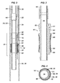
- FIG. 2 illustrates a retrievable annular safety valve 10 integrated in tubing 16 and deployed in casing 22.
- Figure 3 illustrates annular barrier 14 in isolation and
- Figure 4 illustrates a bottom end view of an annular barrier 14.
- Annular barrier 14 is illustrates as a dual cup packer having a top cup packer 48 or downstream cup packer and a bottom cup packer 50 or upstream cup packer.
- Top packer 48 has an open end 68 oriented toward upper annulus 23
- bottom packer 50 has an open end 68 oriented toward lower annulus 25. Pressure in upper annulus 23 expands top cup packer 48 against casing 22 and pressure in lower annulus 25 expands bottom cup packer 50 against casing 22.
- Cup packers 48, 50 are disposed about a feed-through mandrel 52 having a thick side 51.
- Bypass ports are formed longitudinally through thick side 51 of annular barrier 14, for example substantially parallel to tubing bore 36, to pass or form a portion of an annular fluid conduit 54.
- Barrier valve 12 is coupled with fluid conduit 54 to provide one-way upper annulus 23 to lower annulus 25 fluid flow.
- barrier valve 12 is located in a side pocket mandrel 56 integrated, i.e., connected, with tubing 16.
- Annular safety valve 10 is illustrated in Figure 2 eccentrically disposed in casing 22 with side pocket 62 aligned longitudinally with thick side 51 of annular barrier 14.
- One or more additional bypass ports 60 are formed through annular barrier 14, for example feed-through mandrel 52, to pass control lines 38.
- the annular barrier 14 depicted in Figure 4 forms eight bypasses 60 communicating control lines 38.
- Control lines 38 include without limitation, electrical, optic, and hydraulic lines.
- barrier valve 12 is a one-way valve providing fluid connection across annular barrier 14 from upper annulus 23 to lower annulus 25 through passage or conduit 54.
- barrier valve 12 is illustrated located above annular barrier 14 in Figures 1 and 2 , it will be understood by those skilled in the art with benefit of this disclosure that barrier valve 12 can be located below annular barrier 14 to provide fluid communication in the direction from upper annulus 23 to lower annulus 25.
- barrier valve 12 is located in a side pocket mandrel 56.
- Barrier valve 12 is disposed in pocket 62 to provide one-way annulus to annulus fluid communication. Fluid, such as gas 34, flows from upper annulus 23 through port(s) 64 into pocket 62 and through barrier valve 12 into conduit 54 and lower annulus 25.
- Side pocket mandrel 56 may not include a port between tubing-casing annulus 24 and tubing bore 36 or the tubing bore may not be in communication with tubing-casing annulus 24 through barrier valve 12.
- Side pocket mandrel 56 may be a single or a dual pocket mandrel.
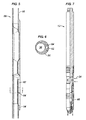
- FIG 7 illustrates a gas lift type barrier valve 12 in accordance to one or more embodiments.
- Barrier valve 12 includes a reverse flow check valve 66 suited for barrier applications.
- barrier valve 12 is a barrier-qualified, reverse flow check valve that provides positive seal between the lower annulus side and the upper annulus side.
- barrier valve 12 has metal-to-meal seal surfaces without elastomers. Some embodiments may have elastomer seal surfaces.
- a non-limiting example of barrier valve 12 is a NOVA 15-B type of gas lift valve available from Schlumberger.
- a surface control system is not required for operation of annular safety valve 10.
- Barrier valve 12 may be retrieved, for example via wireline or slickline, eliminating the need to retrieve the completion, e.g., tubing, to maintain the well integrity. If the pressure in lower annulus 25 exceeds the pressure in upper annulus 23, barrier valve 12 closes. Accordingly, barrier valve 12 fails safe closed if the surface barrier is lost.
- Annular safety valve 10 is insensitive to setting depth.
- barrier valve 12 may be eliminated for example by eliminating or plugging conduit 54. For example, a dummy valve may be landed in pocket 62 to plug conduit 54.
- tubing 16 is made-up at the surface to include annular safety valve 10 located above gas-lift valves 30.
- Side-pocket mandrel 56 and annular barrier 14 are aligned such that side pocket 62 and thick side 51 are aligned longitudinally.
- Fluid conduit 54 is connected with or passed through a bypass port 60 of annular barrier 14.
- Control lines 38 are connected with or passed through bypass ports 60.
- Annular safety valve 10 is run into the wellbore and pressure in tubing-casing annulus 24 acts to seal cup packers 48, 50 with casing 22 separating tubing-casing annulus 24 into an upper annulus 23 and a lower annulus 25.
- Fluid for example gas 34
- upper annulus 23 is communicated from upper annulus 23 through barrier valve 12 and across annular barrier 14 in response to pressure in the upper annulus being greater than pressure in lower annulus 25.
- Gas 34 is injected from lower annulus 25 through gas lift valves 30 into tubing bore 36.
- Barrier valve closes in response to the pressure in upper annulus 23 being less than the pressure in lower annulus 25.
Landscapes
- Life Sciences & Earth Sciences (AREA)
- Engineering & Computer Science (AREA)
- Geology (AREA)
- Mining & Mineral Resources (AREA)
- Physics & Mathematics (AREA)
- Environmental & Geological Engineering (AREA)
- Fluid Mechanics (AREA)
- General Life Sciences & Earth Sciences (AREA)
- Geochemistry & Mineralogy (AREA)
- Consolidation Of Soil By Introduction Of Solidifying Substances Into Soil (AREA)
- Earth Drilling (AREA)
- Structures Of Non-Positive Displacement Pumps (AREA)
Abstract
Description
- This section provides background information to facilitate a better understanding of the various aspects of the disclosure. It should be understood that the statements in this section of this document are to be read in this light, and not as admissions of prior art.
- Hydrocarbon fluids such as oil and natural gas are obtained from a subterranean geological formation, referred to as a reservoir, by drilling a well that penetrates the hydrocarbon-bearing formation. Forms of well completion components may be installed in the wellbore to control and enhance efficiency of producing fluids from the reservoir.
- A well system in accordance to one or more embodiments includes an annular barrier disposed in a tubing-casing annulus of a wellbore separating the tubing-casing annulus into an upper annulus and a lower annulus and a barrier valve coupled with the annular barrier, the barrier valve permitting one-way fluid communication from the upper annulus to the lower annulus. An annular safety valve in accordance with an embodiment includes dual cup packers oriented in opposite direction disposed about a mandrel having a tubing bore, a fluid conduit extending through the dual cup packers substantially parallel to the tubing bore, and a barrier valve in connection with the fluid conduit to permit one-way fluid flow through the fluid conduit. A method includes deploying tubing having a tubing bore in casing in a wellbore, the tubing having a cup packer forming an annular barrier across a tubing-casing annulus, the cup packer having a fluid conduit extending substantially parallel to the tubing bore, and a barrier valve coupled with the fluid conduit to permit one-way fluid flow from the upper annulus to the lower annulus, communicating a fluid from the upper annulus through the barrier valve to the lower annulus, and closing the barrier valve in response to pressure in the upper annulus being less than pressure in the lower annulus.
- The foregoing has outlined some of the features and technical advantages in order that the detailed description of the annular safety valves, systems, and methods that follow may be better understood. Additional features and advantages of the annular safety valve system and method will be described hereinafter which form the subject of the claims of the invention. This summary is not intended to identify key or essential features of the claimed subject matter, nor is it intended to be used as an aid in limiting the scope of claimed subject matter.
- Embodiments of annular safety valves and methods are described with reference to the following figures. The same numbers are used throughout the figures to reference like features and components. It is emphasized that, in accordance with standard practice in the industry, various features are not necessarily drawn to scale. In fact, the dimensions of various features may be arbitrarily increased or reduced for clarity of discussion.
-
Figure 1 illustrates a well system in which an annular safety valve in accordance to one or more embodiments is incorporated. -
Figure 2 illustrates an annular safety valve in accordance to one or more embodiments. -
Figure 3 illustrates an annular barrier in accordance to one or more embodiments. -
Figure 4 is a bottom view illustration of an annular barrier in accordance to one or more embodiments. -
Figure 5 illustrates a side pocket mandrel in accordance to one or more embodiments. -
Figure 6 illustrates a side pocket mandrel along the line I-I ofFigure 5 . -
Figure 7 illustrates a barrier valve in accordance to one or more embodiments. - It is to be understood that the following disclosure provides many different embodiments, or examples, for implementing different features of various embodiments. Specific examples of components and arrangements are described below to simplify the disclosure. These are, of course, merely examples and are not intended to be limiting. In addition, the disclosure may repeat reference numerals and/or letters in the various examples. This repetition is for the purpose of simplicity and clarity and does not in itself dictate a relationship between the various embodiments and/or configurations discussed.
- As used herein, the terms "connect," "connection," "connected," "in connection with," and "connecting" are used to mean "in direct connection with" or "in connection with via one or more elements"; and the term "set" is used to mean "one element" or "more than one element." Further, the terms "couple," "coupling," "coupled," "coupled together," and "coupled with" are used to mean "directly coupled together" or "coupled together via one or more elements." As used herein, the terms "up" and "down," "upper" and "lower," "top" and "bottom," and other like terms indicating relative positions to a given point or element are utilized to more clearly describe some elements. Commonly, these terms relate to a reference point as the surface from which drilling operations are initiated as being the top point and the total depth being the lowest point, wherein the well (e.g., wellbore, borehole) is vertical, horizontal or slanted relative to the surface.
- Generally, a well consists of a wellbore drilled through one or more reservoir production zones. Conductor casing serves as support during drilling operations and provides support for a wellhead and Christmas tree. In offshore wells, a riser may extend the wellbore from the sea floor to the surface platform. One or more strings of casing with diminishing inside diameters will be run inside of the conductor. The well may then be completed with a tubing string extending to the one or more reservoir production zones. The annulus between the tubing and the smallest diameter casing, i.e., the A-annulus, extends from the producing zones to the surface. The surface barrier seals the tubing-casing annulus from the environment. The tubing may be landed for example in a production packer located above the upper most production zone to isolate the annulus from the producing zones. The tubing-casing annulus may extend thousands of feet from the surface to the production packer. The tubing-casing annulus may be utilized for example for gas-injection into the tubing to reduce the density of the fluid in the tubing to facilitate production to the surface. The tubing-casing annulus may be exposed to the surrounding formations via perforations or loss of casing integrity. In the case of failure of the surface annular barrier, for example located at the wellhead, wellbore fluid in the tubing-casing annulus will be in communication with the environment.
- In accordance to one or more embodiments, an annular safety valve is integrated in the tubing to provide an annular safety barrier in the upper completion. In accordance with embodiments, the annular safety valve provides one-way fluid flow from the upper annulus to the lower annulus. In accordance to one or more embodiments, the annular safety valve provides one or more control line bypasses to operationally connect devices in the lower completion below the annular safety valve to surface control systems at the surface or in the upper completion above the annular safety valve. In accordance to one or more embodiments, the annular safety valve is not surface controlled.
-
Figure 1 illustrates awell system 5 in which a subsurface annular safety valve ("ASV"), generally denoted by thenumeral 10, may be incorporated and utilized.Annular safety valve 10 includes a one-way barrier valve 12 coupled with anannular barrier 14. In accordance with embodiments,annular barrier 14 is packer, for example a dual cup packer.Annular barrier 14 provides a sealed annular barrier between the tubing and casing.Barrier valve 12 is illustrated as being located aboveannular barrier 14 inFigure 1 , however, as will be understood by those skilled in the art with benefit of this disclosure,barrier valve 12 may be locate belowannular barrier 14.Barrier valve 12 provides one-way fluid flow in the direction from the upper completion or upper annulus acrossannular barrier 14 to the lower completion or lower annulus. In accordance to one or more embodiments,barrier valve 12 is normally closed, fail safe close, and actuated to the open position in response to pressure in the upper annulus being greater than pressure in the lower annulus. Similarly,barrier valve 12 is actuated to the closed position in response to pressure in the lower annulus exceeding pressure in the upper annulus. -
Well system 5 is illustrated as a gas lift completion that includestubing 16 that extends from an upper orsurface barrier 18 into awellbore 20. A portion ofwellbore 20 is completed withcasing 22. The tubing-casing annulus, generally denoted by the numeral 24, betweentubing 16 andcasing 22 may be referred to as the A-annulus.Surface barrier 18, for example a tubing hanger, is depicted inFigure 1 located at awater surface 26, for example at a platform, e.g., tension leg platform, or ship, positioned above asea floor 28.Surface barrier 18 may be located in the wellhead area. Reference to the surface of the well is not limited to the sea surface or sea floor.Annular safety valve 10 is set in the upper completion and separates tubing-casing annulus 24 into an upper annulus 23 and a lower annulus 25.Tubing 16 may be landed at aproduction packer 9 located isolating lower annulus 25 from aproduction zone 7, i.e., reservoir formation.Production packer 9 may be utilized to anchortubing 16 andannular safety valve 10 withcasing 22. -
Tubing 16 incorporates one or moregas lift valves 30 which are located in the lower tubing section 17 belowannular safety valve 10 inwellbore 20. For purposes of gas injection, wellsystem 5 includes agas compressor 32 located at the surface to pressurize gas that is communicated to tubing-casing annulus 24. Thepressurized gas 34 is communicated from upper annulus 23 throughannular safety valve 10 to lower annulus 25. Thepressurized gas 34 is communicated from lower annulus 25 into tubing bore 36 throughgas lift valves 30. - One or
more control lines 38 may extend from asurface system 40, for example an electronic controller and or pressurized fluid source, to downhole devices, generally denoted by the numeral 42, located belowannular safety valve 10. Downhole devices 42 may include devices such as, and without limitation to, pressure, temperature, and flow rate sensors 43, chemical injection valves 45, and flow control valves 47. In accordance to one or more embodiments,annular safety valve 10 provides control line bypasses from the upper completion or surface to the lower completion while maintaining an annular barrier. - Together,
annular safety valve 10 andtubing 16 can serve as a primary barrier to maintain well integrity. In the depicted embodiment, adownhole safety valve 44 is located in the upper section 15 oftubing 16, for example proximate toannular barrier 14, to provide a vertical barrier through tubing bore 36. In this example,downhole safety valve 44 is a surface controlled subsurface safety valve ("SCSSV") connected to the surface via acontrol line 38.Subsurface safety valve 44 may be a wireline or tubing set type.Annular safety valve 10 serves as a safety barrier in A-annulus 24 in the event that surfacebarrier 18 is lost. Lower annulus 25 although located aboveproduction packer 9 inFigure 1 , may be in communication with formation fluids and pressure. For example, perforations or loss integrity ofcasing 22 may expose tubing-casing annulus 24 to the surroundingformation 46. InFigure 1 , gas lift injection through lower annulus 25 may temporarily superchargeformation 46. -
Figure 2 illustrates a retrievableannular safety valve 10 integrated intubing 16 and deployed incasing 22.Figure 3 illustratesannular barrier 14 in isolation andFigure 4 illustrates a bottom end view of anannular barrier 14.Annular barrier 14 is illustrates as a dual cup packer having atop cup packer 48 or downstream cup packer and abottom cup packer 50 or upstream cup packer.Top packer 48 has anopen end 68 oriented toward upper annulus 23 andbottom packer 50 has anopen end 68 oriented toward lower annulus 25. Pressure in upper annulus 23 expandstop cup packer 48 againstcasing 22 and pressure in lower annulus 25 expandsbottom cup packer 50 againstcasing 22. -
Cup packers mandrel 52 having athick side 51. Bypass ports, generally denoted by thereference number 60, are formed longitudinally throughthick side 51 ofannular barrier 14, for example substantially parallel to tubing bore 36, to pass or form a portion of anannular fluid conduit 54.Barrier valve 12 is coupled withfluid conduit 54 to provide one-way upper annulus 23 to lower annulus 25 fluid flow. InFigure 2 ,barrier valve 12 is located in aside pocket mandrel 56 integrated, i.e., connected, withtubing 16.Annular safety valve 10 is illustrated inFigure 2 eccentrically disposed in casing 22 withside pocket 62 aligned longitudinally withthick side 51 ofannular barrier 14. - One or more
additional bypass ports 60 are formed throughannular barrier 14, for example feed-throughmandrel 52, to pass control lines 38. Theannular barrier 14 depicted inFigure 4 forms eightbypasses 60 communicatingcontrol lines 38.Control lines 38 include without limitation, electrical, optic, and hydraulic lines. - With reference in particular to
Figures 1-2 and5-6 ,barrier valve 12 is a one-way valve providing fluid connection acrossannular barrier 14 from upper annulus 23 to lower annulus 25 through passage orconduit 54. Althoughbarrier valve 12 is illustrated located aboveannular barrier 14 inFigures 1 and2 , it will be understood by those skilled in the art with benefit of this disclosure thatbarrier valve 12 can be located belowannular barrier 14 to provide fluid communication in the direction from upper annulus 23 to lower annulus 25. - In accordance to one or more embodiments,
barrier valve 12 is located in aside pocket mandrel 56.Barrier valve 12 is disposed inpocket 62 to provide one-way annulus to annulus fluid communication. Fluid, such asgas 34, flows from upper annulus 23 through port(s) 64 intopocket 62 and throughbarrier valve 12 intoconduit 54 and lower annulus 25.Side pocket mandrel 56 may not include a port between tubing-casing annulus 24 and tubing bore 36 or the tubing bore may not be in communication with tubing-casing annulus 24 throughbarrier valve 12.Side pocket mandrel 56 may be a single or a dual pocket mandrel. -
Figure 7 illustrates a gas lifttype barrier valve 12 in accordance to one or more embodiments.Barrier valve 12 includes a reverseflow check valve 66 suited for barrier applications. For example,barrier valve 12 is a barrier-qualified, reverse flow check valve that provides positive seal between the lower annulus side and the upper annulus side. In accordance to one or more embodiments,barrier valve 12 has metal-to-meal seal surfaces without elastomers. Some embodiments may have elastomer seal surfaces. A non-limiting example ofbarrier valve 12 is a NOVA 15-B type of gas lift valve available from Schlumberger. - In accordance to one or more embodiments, a surface control system is not required for operation of
annular safety valve 10.Barrier valve 12 may be retrieved, for example via wireline or slickline, eliminating the need to retrieve the completion, e.g., tubing, to maintain the well integrity. If the pressure in lower annulus 25 exceeds the pressure in upper annulus 23,barrier valve 12 closes. Accordingly,barrier valve 12 fails safe closed if the surface barrier is lost.Annular safety valve 10 is insensitive to setting depth. In accordance with one or more embodiments,barrier valve 12 may be eliminated for example by eliminating or pluggingconduit 54. For example, a dummy valve may be landed inpocket 62 to plugconduit 54. - A method in accordance to one or more embodiments is now described with reference to
Figures 1-7 . When running the completion,tubing 16 is made-up at the surface to includeannular safety valve 10 located above gas-lift valves 30. Side-pocket mandrel 56 andannular barrier 14 are aligned such thatside pocket 62 andthick side 51 are aligned longitudinally.Fluid conduit 54 is connected with or passed through abypass port 60 ofannular barrier 14.Control lines 38 are connected with or passed throughbypass ports 60.Annular safety valve 10 is run into the wellbore and pressure in tubing-casing annulus 24 acts to sealcup packers casing 22 separating tubing-casing annulus 24 into an upper annulus 23 and a lower annulus 25. Fluid, forexample gas 34, is communicated from upper annulus 23 throughbarrier valve 12 and acrossannular barrier 14 in response to pressure in the upper annulus being greater than pressure in lower annulus 25.Gas 34 is injected from lower annulus 25 throughgas lift valves 30 into tubing bore 36. Barrier valve closes in response to the pressure in upper annulus 23 being less than the pressure in lower annulus 25. - The foregoing outlines features of several embodiments of annular safety valves, systems, and methods so that those skilled in the art may better understand the aspects of the disclosure. Those skilled in the art should appreciate that they may readily use the disclosure as a basis for designing or modifying other processes and structures for carrying out the same purposes and/or achieving the same advantages of the embodiments introduced herein. Those skilled in the art should also realize that such equivalent constructions do not depart from the spirit and scope of the disclosure, and that they may make various changes, substitutions and alterations herein without departing from the spirit and scope of the disclosure. The scope of the invention should be determined only by the language of the claims that follow. The term "comprising" within the claims is intended to mean "including at least" such that the recited listing of elements in a claim are an open group. The terms "a," "an" and other singular terms are intended to include the plural forms thereof unless specifically excluded.
Claims (16)
- A well system, comprising:a wellbore extending downward from a surface, the wellbore comprising a tubing deployed in a casing;an annular barrier disposed in a tubing-casing annulus separating the tubing-casing annulus into an upper annulus and a lower annulus; anda barrier valve coupled with the annular barrier permitting one-way fluid communication from the upper annulus to the lower annulus.
- The well system of claim 1, wherein the annular barrier is a packer.
- The well system of claim 1, wherein the annular barrier comprises:a top cup packer having an open end oriented toward the upper annulus; anda bottom cup packer having an open end oriented toward the lower annulus.
- The well system of claim 1, further comprising a control line passing through the annular barrier.
- The well system of claim 1, wherein the barrier valve is disposed in a side pocket mandrel integrated in the tubing.
- The well system of claim 1, wherein the barrier valve is located above the annular barrier.
- The well system of claim 1, wherein the barrier valve is operated to an open position in response to pressure in the upper annulus being greater than pressure in the lower annulus.
- The well system of claim 1, wherein the barrier valve is located in a side pocket mandrel integrated in the tubing; and
the annular barrier comprises:a top cup packer having an open end oriented toward the upper annulus; and a bottom cup packer having an open end oriented toward the lower annulus. - The well system of claim 8, further comprising gas lift valves located in the tubing below the annular barrier.
- The well system of claim 9, further comprising a control line extending from above the annular barrier through the annular barrier to a device located below the annular barrier.
- A method, comprising:deploying a tubing having a tubing bore in a casing in a wellbore, the tubing comprising a cup packer forming an annular barrier across a tubing-casing annulus separating the tubing-casing annulus into an upper annulus and a lower annulus, the cup packer having a fluid conduit extending substantially parallel to the tubing bore, and a barrier valve coupled with the fluid conduit to permit one-way fluid flow from the upper annulus to the lower annulus;communicating a fluid from the upper annulus through the barrier valve to the lower annulus; andclosing the barrier valve in response to pressure in the upper annulus being less than pressure in the lower annulus.
- The method of claim 11, wherein the fluid is a pressurized gas and further comprising injecting the pressurized gas from the lower annulus through a gas lift valve into the tubing bore.
- The method of claim 11, further comprising a control line extending from the upper annulus through the annular barrier to the lower annulus.
- The method of claim 11, wherein the barrier valve is located in a side pocket mandrel integrated in the tubing.
- The method of claim 11, wherein the barrier valve is normally closed and the barrier valve is opened in response to pressure in the upper annulus being greater than pressure in the lower annulus.
- The method of claim 13, wherein:the barrier valve is located in a side pocket mandrel integrated in the tubing;the fluid is a pressurized gas; andfurther comprising injecting the pressurized gas from the lower annulus through a gas lift valve into the tubing bore.
Applications Claiming Priority (1)
| Application Number | Priority Date | Filing Date | Title |
|---|---|---|---|
| US13/973,699 US10563488B2 (en) | 2013-08-22 | 2013-08-22 | Wellbore annular safety valve and method |
Publications (2)
| Publication Number | Publication Date |
|---|---|
| EP2840227A2 true EP2840227A2 (en) | 2015-02-25 |
| EP2840227A3 EP2840227A3 (en) | 2015-12-30 |
Family
ID=51383629
Family Applications (1)
| Application Number | Title | Priority Date | Filing Date |
|---|---|---|---|
| EP14181745.2A Withdrawn EP2840227A3 (en) | 2013-08-22 | 2014-08-21 | Wellbore annular safety valve and method |
Country Status (2)
| Country | Link |
|---|---|
| US (2) | US10563488B2 (en) |
| EP (1) | EP2840227A3 (en) |
Families Citing this family (7)
| Publication number | Priority date | Publication date | Assignee | Title |
|---|---|---|---|---|
| US20150053415A1 (en) * | 2013-08-22 | 2015-02-26 | Schlumberger Technology Corporation | Wellbore annular safety valve and method |
| BR102019021843A2 (en) * | 2019-10-17 | 2021-04-27 | Ouro Negro Tecnologias Em Equipamentos Industriais S/A | CONTROL SYSTEM AND VALVE SAFETY BY ELECTRIC ACTIVATION FOR GAS INJECTION IN OIL PRODUCTION COLUMN |
| US12123277B2 (en) * | 2021-06-02 | 2024-10-22 | Halliburton Energy Services, Inc. | Sealing assembly for wellbore operations |
| US20230075579A1 (en) * | 2021-09-09 | 2023-03-09 | Baker Hughes Oilfield Operations Llc | Pseudoplastic flow control device, method and system |
| CN114135253A (en) * | 2021-12-22 | 2022-03-04 | 西南石油大学 | A Novel Multifunctional Gas Lift String |
| US12129745B2 (en) | 2023-02-24 | 2024-10-29 | Weatherford Technology Holdings, Llc | Deep gas-lift in compromised wells |
| US12534968B2 (en) * | 2024-03-04 | 2026-01-27 | Halliburton Energy Services, Inc. | Splice free feedthrough mechanical packer |
Family Cites Families (23)
| Publication number | Priority date | Publication date | Assignee | Title |
|---|---|---|---|---|
| US2798558A (en) * | 1955-01-10 | 1957-07-09 | Exxon Research Engineering Co | Well completion apparatus |
| US2896547A (en) * | 1955-02-14 | 1959-07-28 | Pan American Petroleum Corp | Gas lifting dually-completed wells |
| US3659961A (en) * | 1970-08-07 | 1972-05-02 | Teledyne Inc | Gas lift system |
| US3746089A (en) * | 1971-07-19 | 1973-07-17 | Dresser Ind | Apparatus for producing multiple zone oil and gas wells |
| US4398555A (en) * | 1981-06-03 | 1983-08-16 | Otis Engineering Corporation | Flow control valve |
| US4545731A (en) * | 1984-02-03 | 1985-10-08 | Otis Engineering Corporation | Method and apparatus for producing a well |
| US4589482A (en) * | 1984-06-04 | 1986-05-20 | Otis Engineering Corporation | Well production system |
| US4708595A (en) * | 1984-08-10 | 1987-11-24 | Chevron Research Company | Intermittent oil well gas-lift apparatus |
| US4632184A (en) * | 1985-10-21 | 1986-12-30 | Otis Engineering Corporation | Submersible pump safety systems |
| NO903764L (en) * | 1989-08-31 | 1991-03-01 | British Petroleum Co Plc | Annulus SAFETY VALVE. |
| US5022427A (en) * | 1990-03-02 | 1991-06-11 | Otis Engineering Corporation | Annular safety system for gas lift production |
| US5048610A (en) | 1990-03-09 | 1991-09-17 | Otis Engineering Corporation | Single bore packer with dual flow conversion for gas lift completion |
| US5875852A (en) * | 1997-02-04 | 1999-03-02 | Halliburton Energy Services, Inc. | Apparatus and associated methods of producing a subterranean well |
| US6298916B1 (en) | 1999-12-17 | 2001-10-09 | Schlumberger Technology Corporation | Method and apparatus for controlling fluid flow in conduits |
| US6745844B2 (en) * | 2002-03-19 | 2004-06-08 | Halliburton Energy Services, Inc. | Hydraulic power source for downhole instruments and actuators |
| CA2448405C (en) | 2002-11-07 | 2007-08-07 | Schlumberger Canada Limited | Subsurface annular safety barrier |
| US7770637B2 (en) * | 2007-10-12 | 2010-08-10 | Ptt Exploration And Production Public Company Limited | Bypass gas lift system and method for producing a well |
| US8191624B2 (en) * | 2007-10-12 | 2012-06-05 | PTT Exploration and Production Public Company Limited. | Bypass gas lift system for producing a well |
| US8037938B2 (en) * | 2008-12-18 | 2011-10-18 | Smith International, Inc. | Selective completion system for downhole control and data acquisition |
| US8418768B2 (en) * | 2009-12-09 | 2013-04-16 | Ptt Exploration And Production Public Company Ltd. | Bypass gaslift system, apparatus, and method for producing a multiple zones well |
| US9416596B2 (en) * | 2010-06-15 | 2016-08-16 | Halliburton Energy Services, Inc. | Installation of lines in high temperature wellbore environments |
| CA2823211C (en) * | 2011-01-07 | 2018-10-30 | Weatherford/Lamb, Inc. | Test packer and method for use |
| WO2013062566A1 (en) | 2011-10-28 | 2013-05-02 | Halliburton Energy Services, Inc. | Downhole packer assembly having a selective fluid bypass and method for use thereof |
-
2013
- 2013-08-22 US US13/973,699 patent/US10563488B2/en active Active
-
2014
- 2014-08-21 EP EP14181745.2A patent/EP2840227A3/en not_active Withdrawn
-
2020
- 2020-02-14 US US16/791,325 patent/US11111764B2/en active Active
Non-Patent Citations (1)
| Title |
|---|
| None |
Also Published As
| Publication number | Publication date |
|---|---|
| US20200182026A1 (en) | 2020-06-11 |
| US11111764B2 (en) | 2021-09-07 |
| US20150053416A1 (en) | 2015-02-26 |
| EP2840227A3 (en) | 2015-12-30 |
| US10563488B2 (en) | 2020-02-18 |
Similar Documents
| Publication | Publication Date | Title |
|---|---|---|
| US10174582B2 (en) | Wellbore annular safety valve and method | |
| US11111764B2 (en) | Wellbore annular safety valve and method | |
| US9945203B2 (en) | Single trip completion system and method | |
| US20140209318A1 (en) | Gas lift apparatus and method for producing a well | |
| US20130037272A1 (en) | Method and system for well access to subterranean formations | |
| WO2014089132A1 (en) | Tubing movement compensation joint | |
| US10392907B2 (en) | Subsea system and method for high pressure high temperature wells | |
| US10697264B2 (en) | Subsea system and method for high pressure high temperature wells | |
| US20150041129A1 (en) | Steam injection and production completion system | |
| US9567829B2 (en) | Dual barrier open water completion | |
| EP2840228A2 (en) | Wellbore Annular Safety Valve and Method | |
| DK202430127A8 (en) | Well Sealing Tool with Isolatable Setting Chamber | |
| US9404350B2 (en) | Flow-activated flow control device and method of using same in wellbores | |
| US7140447B2 (en) | Subsurface annular safety barrier | |
| US10570714B2 (en) | System and method for enhanced oil recovery | |
| WO2020036914A1 (en) | Bottom hole assembly deployment | |
| Carpenter | Integrated Approach Improves Completion Reliability Using Compact Horizontal Wellhead | |
| RU2799592C2 (en) | Method for deploying integrated completion case in one ride and completion system | |
| Brown et al. | A review of current practices for the completion, stimulation and workover of oil and gas wells in the North Sea area | |
| Yonker et al. | Newest Pumpdown (TFL) Completion Capabilities |
Legal Events
| Date | Code | Title | Description |
|---|---|---|---|
| PUAI | Public reference made under article 153(3) epc to a published international application that has entered the european phase |
Free format text: ORIGINAL CODE: 0009012 |
|
| 17P | Request for examination filed |
Effective date: 20140821 |
|
| AK | Designated contracting states |
Kind code of ref document: A2 Designated state(s): AL AT BE BG CH CY CZ DE DK EE ES FI FR GB GR HR HU IE IS IT LI LT LU LV MC MK MT NL NO PL PT RO RS SE SI SK SM TR |
|
| AX | Request for extension of the european patent |
Extension state: BA ME |
|
| PUAL | Search report despatched |
Free format text: ORIGINAL CODE: 0009013 |
|
| AK | Designated contracting states |
Kind code of ref document: A3 Designated state(s): AL AT BE BG CH CY CZ DE DK EE ES FI FR GB GR HR HU IE IS IT LI LT LU LV MC MK MT NL NO PL PT RO RS SE SI SK SM TR |
|
| AX | Request for extension of the european patent |
Extension state: BA ME |
|
| RIC1 | Information provided on ipc code assigned before grant |
Ipc: E21B 33/126 20060101AFI20151123BHEP Ipc: E21B 43/12 20060101ALI20151123BHEP Ipc: E21B 34/10 20060101ALI20151123BHEP |
|
| STAA | Information on the status of an ep patent application or granted ep patent |
Free format text: STATUS: THE APPLICATION IS DEEMED TO BE WITHDRAWN |
|
| 18D | Application deemed to be withdrawn |
Effective date: 20160701 |