EP2840039A1 - Combined drape and carrying bag unit - Google Patents
Combined drape and carrying bag unit Download PDFInfo
- Publication number
- EP2840039A1 EP2840039A1 EP14186049.4A EP14186049A EP2840039A1 EP 2840039 A1 EP2840039 A1 EP 2840039A1 EP 14186049 A EP14186049 A EP 14186049A EP 2840039 A1 EP2840039 A1 EP 2840039A1
- Authority
- EP
- European Patent Office
- Prior art keywords
- sheet
- drawstring
- mat
- casing
- periphery
- Prior art date
- Legal status (The legal status is an assumption and is not a legal conclusion. Google has not performed a legal analysis and makes no representation as to the accuracy of the status listed.)
- Granted
Links
Images




Classifications
-
- A—HUMAN NECESSITIES
- A45—HAND OR TRAVELLING ARTICLES
- A45C—PURSES; LUGGAGE; HAND CARRIED BAGS
- A45C9/00—Purses, Luggage or bags convertible into objects for other use
-
- A—HUMAN NECESSITIES
- A61—MEDICAL OR VETERINARY SCIENCE; HYGIENE
- A61B—DIAGNOSIS; SURGERY; IDENTIFICATION
- A61B46/00—Surgical drapes
-
- A—HUMAN NECESSITIES
- A61—MEDICAL OR VETERINARY SCIENCE; HYGIENE
- A61B—DIAGNOSIS; SURGERY; IDENTIFICATION
- A61B50/00—Containers, covers, furniture or holders specially adapted for surgical or diagnostic appliances or instruments, e.g. sterile covers
- A61B50/30—Containers specially adapted for packaging, protecting, dispensing, collecting or disposing of surgical or diagnostic appliances or instruments
- A61B50/36—Containers specially adapted for packaging, protecting, dispensing, collecting or disposing of surgical or diagnostic appliances or instruments for collecting or disposing of used articles
-
- A—HUMAN NECESSITIES
- A45—HAND OR TRAVELLING ARTICLES
- A45C—PURSES; LUGGAGE; HAND CARRIED BAGS
- A45C11/00—Receptacles for purposes not provided for in groups A45C1/00-A45C9/00
-
- A—HUMAN NECESSITIES
- A45—HAND OR TRAVELLING ARTICLES
- A45C—PURSES; LUGGAGE; HAND CARRIED BAGS
- A45C13/00—Details; Accessories
- A45C13/10—Arrangement of fasteners
- A45C13/1038—Arrangement of fasteners of flexible ties
- A45C13/1046—Arrangement of fasteners of flexible ties of strings or cords
-
- A—HUMAN NECESSITIES
- A45—HAND OR TRAVELLING ARTICLES
- A45C—PURSES; LUGGAGE; HAND CARRIED BAGS
- A45C11/00—Receptacles for purposes not provided for in groups A45C1/00-A45C9/00
- A45C2011/007—Receptacles for personal medical or care products, e.g. drugs, condoms or patches; Small first-aid kits
-
- A—HUMAN NECESSITIES
- A45—HAND OR TRAVELLING ARTICLES
- A45C—PURSES; LUGGAGE; HAND CARRIED BAGS
- A45C3/00—Flexible luggage; Handbags
- A45C3/001—Flexible materials therefor
-
- A—HUMAN NECESSITIES
- A45—HAND OR TRAVELLING ARTICLES
- A45C—PURSES; LUGGAGE; HAND CARRIED BAGS
- A45C3/00—Flexible luggage; Handbags
- A45C3/10—Beach-bags; Watertight beach-bags
-
- A—HUMAN NECESSITIES
- A61—MEDICAL OR VETERINARY SCIENCE; HYGIENE
- A61B—DIAGNOSIS; SURGERY; IDENTIFICATION
- A61B50/00—Containers, covers, furniture or holders specially adapted for surgical or diagnostic appliances or instruments, e.g. sterile covers
- A61B2050/005—Containers, covers, furniture or holders specially adapted for surgical or diagnostic appliances or instruments, e.g. sterile covers with a lid or cover
- A61B2050/0067—Types of closures or fasteners
- A61B2050/0071—Draw-strings
-
- A—HUMAN NECESSITIES
- A61—MEDICAL OR VETERINARY SCIENCE; HYGIENE
- A61B—DIAGNOSIS; SURGERY; IDENTIFICATION
- A61B50/00—Containers, covers, furniture or holders specially adapted for surgical or diagnostic appliances or instruments, e.g. sterile covers
- A61B50/30—Containers specially adapted for packaging, protecting, dispensing, collecting or disposing of surgical or diagnostic appliances or instruments
- A61B2050/314—Flexible bags or pouches
-
- A—HUMAN NECESSITIES
- A61—MEDICAL OR VETERINARY SCIENCE; HYGIENE
- A61B—DIAGNOSIS; SURGERY; IDENTIFICATION
- A61B46/00—Surgical drapes
- A61B46/20—Surgical drapes specially adapted for patients
- A61B46/23—Surgical drapes specially adapted for patients with means to retain or hold surgical implements
Definitions
- the invention generally relates to the use of a disposable absorbent article in covering medical carts for medical applications used in medical procedure rooms, and in particular to a drape for use in conjunction with endoscopic procedures for containment of waste product and equipment protection.
- Conventional disposable absorbent drapes or pads used in endoscopic procedures may be comprised of a plurality of absorbent and impermeable material layers joined mechanically to produce a sterile mat of given geometry. Said mats are placed upon medical carts for establishment of a sterile work platform to place endoscopic and other medical instruments upon, beneath the patient procedure zone to contain wastes emanating from the procedure due to gravitational flow from the patients body, and such other areas in the procedural region to allow for capture of waste or the establishment of a sterile work surface.
- a conventional absorbent drape once the procedure is complete, the equipment involved in the procedure, which is now contaminated, is removed from the area by medical personnel.
- the equipment may be placed in a separate container for transport, or left exposed to the environment and carried to a decontamination/sterilization area for preparation for the next procedural use.
- the absorbent disposable drapes used in the procedure are gathered by medical personnel and may also be placed in containers or receptacles for proper disposal of biohazard materials.
- the present invention provides a disposable absorbent drape or pad having none of the shortcomings of the present art.
- the present invention generally comprises a disposable absorbent drape or pad, to which about the periphery of the pad an annular feature has been applied facilitating the internal positioning within this annulus of a member functioning as a draw cord for gathering and shortening the perimeter of the drape or pad.
- the draw cord is stored within the annulus and exposed for a portion of the length of the annulus to allow for medical personnel to grasp the draw cord and proceed to pull the draw cord out of the annulus, thereby shortening the perimeter of the drape or pad and causing a gathering of the drape or pad material into a carrying bag.
- the disposable absorbent drape or pad has an elongated square, or rectangular, shape, and the annulus extends around the rectangular periphery thereof.
- the disposable absorbent drape or pad has an elongated square, or rectangular, shape with rounded sides, and the annulus extends around the periphery thereof.
- the disposable absorbent drape or pad has an elongated octagonal shape, and the annulus extends around the periphery thereof.
- a carrying bag is formed through said operation which can support the weight of the endoscopic equipment used in the procedure therein.
- a sterile outer surface of the gathered invention can be used for disposal or transport of the waste materials or contaminated equipment without placement of same into a separate container.
- the present invention thereby reduces the biohazard exposure to medical personnel handling these components post-procedure, and also offers simultaneous protection from damage to the endoscopic equipment during transport from the procedural area.
- a primary object of the present invention is to provide a combined drape and carrying bag unit that overcomes the shortcomings of prior art devices.
- the present invention is directed to the use of a combined drape and carrying bag unit for use as a sterile or non-sterile surface mat during endoscopic procedures and conversion of same through operation of embodied features therein to a carrying bag for the containment of procedural equipment and waste post-procedure.
- the present invention comprises a combination drape and carrying bag unit which includes a singular sheet or plurality of joined or attached sheet of pliable materials, both permeable and impermeable, of size to define a mat to accommodate a working medical procedural area thereon, upon which may be placed in single or combination, medical equipment and patient.
- a drawstring casing extends about the periphery of the drape and has a plurality of openings therein.
- a drawstring is received in the drawstring casing and is of size to extend about the periphery of the drape when it defines a mat.
- the drawstring is slidably received in the drawstring casing so that when portions of the drawstring are pulled out of the drawstring casing through the openings, the periphery of the drape forms gathers adjacent the casing to permit the periphery to reduce in size and form a carrying bag.
- the drape has a generally rectangular periphery defined by two generally parallel side edges and two generally parallel end edges, the side edges being longer than and generally perpendicular to the end edges.
- the drawstring casing has including, but not limited to, two openings positioned proximate the midpoints of those portions of the casing which extend along the end edges.
- the sheets of pliable material preferably comprises a first generally rectangular sheet of permeable fabric, a second generally rectangular sheet of fluid impermeable fabric and a generally rectangular layer of resilient absorbent material secured between the first and second sheets.
- Plurality and combination of said sheets may be varied to accommodate absorption, sterility, volume, density, and other material properties.
- a combined drape and carrying bag unit 10 of the present invention is shown in use as a mat 12 in FIG. 1 .
- the mat 12 is of size to accommodate a patient's procedural volume 14 thereon and is suitable for use as a sterile or non-sterile procedural mat, medical cart mat, prep area mat, or the like.
- the unit 10 is preferably comprised of a first sheet of permeable pliable fabric 16, a second sheet of impermeable pliable fabric 18 and a layer of resilient absorbent material 20 which is secured between the first and second sheets 16 and 18.
- First sheet of pliable fabric 16 preferably comprises a layer of woven material, which is soft and pliable enough to be comfortable against the skin of a person 14 using the mat, satisfies procedural sterility requirements, and is durable enough to withstand procedural structural and biological demands.
- the layer of absorbent material 20 is typically of sterile fluid retention capable medical fiber, and is held generally in place between the first and second sheets 16 and 18 by stitching or quilting the sheets and cushioning material together using sterile joining practices for medical mats as illustrated at 22 in FIG. 2 .
- the first and second sheets 16 and 18 and the layer of resilient absorbent material 20 are generally rectangular in shape so as to define a uniformly and fully cushioned mat 12, as shown in FIG. 1 .
- the first and second sheets 16 and 18 are secured together about their edges (as at 24 in FIG. 2 ) so that the layer of absorbent material 20 is fully encased by the first and second sheets 16 and 18.
- the first sheet 16, second sheet 18 and layer of absorbent material 20 thus combine to form a mat 12 having a generally rectangular periphery.
- the periphery of the mat 12 is defined by two generally parallel side edges 26 and 28 and two generally parallel end edges 30 and 32, with the side edges 26 and 28 being longer than and generally perpendicular to the end edges 30 and 32.
- the layer of resilient absorbent material 20 does not cover the same geometric surface area as do the first and second sheets 16 and 18.
- the layer of resilient absorbent material 20 may cover only the central portion of mat 12 and leave certain regions closest to the side edges 26 and 28 thereof, or alternatively leave certain regions closest to the end edges 30 and 32 thereof, without the layer of resilient absorbent material 20, i.e., with only the first and second sheets 16 and 18.
- the layer of resilient absorbent material 20 covers only the central area of mat 12 and leaves regions closest to both the side edges 26 and 28 and the end edges 30 and 32 thereof without the layer of resilient absorbent material 20, i.e., with only the first and second sheets 16 and 18.
- mat 12 is generally rectangular in shape, it is not a uniformly cushioned mat 12, as shown in FIG. 1 , but rather contains cushioning and absorbency only in its central region or in its central longitudinal or central transverse region.
- a hem 33 extends about the entire periphery of the mat 12 to define a drawstring casing or passageway 34.
- the drawstring casing 34 is formed by outer portions 36 and 38 of the first and second sheets 16 and 18 respectively.
- the outer edge portions 36 and 38 are secured together adjacent the periphery of the layer of absorbent cushioning material 20 as at 24 and are sewed or welded together by stitching means as at 40 as illustrated in FIG. 2 .
- the drawstring casing 34 or passageway is formed there-between.
- the outer edge portions 36 and 38 of the first and second sheet 16 and 18 are secured in this manner completely about the peripheries of the sheets 16 and 18, thus creating a drawstring casing 34 extending about the entire periphery of the mat 12.
- the unit 10 may be comprised of a sheet of resilient absorbent material 20 that is adhered or bonded to a sheet of impermeable pliable fabric 18.
- the sheet of absorbent material 20 is typically of sterile fluid retention capable medical fiber.
- the sheet of absorbent material 20 should also be soft and pliable enough to be comfortable against the skin of a person using the mat 12, satisfy procedural sterility requirements, and be durable enough to withstand procedural structural and biological demands.
- the sheet of absorbent material 20 is held in place generally against the sheet of impermeable pliable fabric 18 by bonding or adhering with a standard medical grade adhesive, and alternatively also by stitching or quilting the sheets and cushioning material together using sterile joining practices for medical mats.
- the sheet of resilient absorbent material 20 does not cover the same geometric surface area as does the sheet of impermeable pliable fabric 18.
- the sheet of resilient absorbent material 20 may cover only the central portion of mat 12 and leave certain regions 27 closest to either or both of the side edges 26 and 28 thereof and the end edges 30 and 32 thereof without the sheet of resilient absorbent material 20, i.e., with only the sheet of impermeable pliable fabric 18.
- a hem 33 extends about the entire periphery of the mat 12 to define a drawstring casing or passageway 34, which is formed by folding over the peripheral edge of sheet 18 and sewing or welding together the overlapping edge portions of sheet 18 by stitching means as at 40, as illustrated in FIG. 5 , thus forming drawstring casing 34 or passageway there-between.
- the overlapping edge portions of sheet 18 is secured in this manner completely about the periphery thereof, thus creating a drawstring casing 34 extending about the entire periphery of the mat 12.
- the hem 33 has a first opening 42 and a second opening 44 therein, with each opening communicating with the passageway or drawstring casing 34.
- the openings 42 and 44 extend through that part of the outer edge portions 36 and 38 which would be otherwise fastened as at 40.
- the first opening 42 is positioned proximate the midpoint of the end edge 30 of the mat 12 and the second opening 44 is positioned proximate the midpoint of the end edge 32 of the mat 12.
- the first and second openings 42 and 44 are thus on opposite ends of the mat 12.
- a sterile or non-sterile cord or drawstring 50 is received in the drawstring casing 34 and is of size to extend about the periphery of the unit 10 when it defines a mat 12 as illustrated in FIGS. 1 , 3 and 5 .
- the drawstring 50 is slidably received in the drawstring casing 34 so that its movement within the drawstring casing 34 about the periphery of mat 12 is unrestricted.
- the drawstring 50 is endless, with a first portion 52 of the drawstring 50 extending past the first opening 42 of the casing 34 and a second portion 54 of the drawstring 50 extending past the second opening 44 of the casing 34.
- the first and second portions 52 and 54 are thus always accessible through their respective openings 42 and 44.
- the hem 33 of the mat 12 has first and second openings 42 and 44 therein that communicate with the passageway or drawstring casing 34, as in FIG. 3 , but the openings 42 and 44 that extend through that part of the outer edge portions 36 and 38 that would be otherwise fastened as at 40 are positioned proximate the midpoints of the side edges 26 and 28, respectively, of the mat 12, rather than proximate the midpoints of end edges 30 and 32 of the mat 12.
- the first and second openings 42 and 44 are thus on opposite sides of the mat 12, rather than on opposite ends of the mat 12.
- the first and second portions 52 and 54 of the drawstring 50 are pulled out of the drawstring casing 34 through their respective openings 42 and 44.
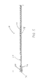
- the drawstring portions 52 and 54 are pulled in direction out of and away from the drawstring casing 34 generally as indicated by arrows 56 and 58, respectively, in FIG. 3 .
- the drawstring casing 34, first sheet 16, second sheet 18 and layer of absorbent material 20 form gathers 60 adjacent the periphery of the unit 10 to permit the periphery thereof to reduce in size.
- the drawing together or contraction of the hem 33 and casing 34 causes the casing 34 to pucker or ruffle to form the gathers 60.
- the first and second sheets 16 and 18 and layer of resilient absorbent material 20 adjacent the casing 34 also pucker or contract together as the gathers 60 are formed.
- the edges of the mat 12 are drawn together to cause the unit 10 to form a carrying bag 62.
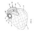
- the unit 10 defines a carrying bag 62 as illustrated in FIG. 4
- the first sheet 16 forms an interior surface of the carrying bag 62
- the second sheet 18 forms an exterior surface of the carrying bag 62.
- procedural equipment and contained procedural waste such as endoscopic procedure equipment and bodily fluids (designated generally as at 64 in FIG. 3 ) can be carried within the carrying bag 62.
- the volume of the carrying bag 62 is dependent upon the size of the mat 12 defined by the unit 10.
- the carrying bag 62 Because of the pliable nature of the materials comprising the carrying bag 62, it is a highly efficient carrier of materials, capable of defining its shape about the articles to be carried and cushioning the contents therein, and having a large capacity or carrying volume. Also, due to the impermeability and sterility of the second sheet 18 construction, and its facing opposite of the procedural surface first sheet 16, a containment bag for biohazard waste having a sterile or non-sterile outer surface is formed without the use of an external separate containment component having to be employed or the mat and equipment having to be placed within.
- a handle portion 66 for the carrying bag 62 is created by securing the drawstring portions 52 and 54 together once they have been pulled out of their respective openings 42 and 44.
- the drawstring portions 52 and 54 are secured together adjacent or proximate to their respective openings 42 and 44 as shown in FIG. 4 .
- the drawstring portions 52 and 54 can be secured together by tying them together or by other suitable fastening means.
- the handle portion 66 comprises portions of the sheet adjacent the drawstring casing 34 and portions of the drawstring 50.
- the combined drape and carrying bag unit 10 can be easily transported from the procedural area while carrying equipment, waste, or other articles. Because the carrying bag 62 has the layer of resilient absorbent material 20 between its exterior surface and interior surface, the articles carried therein are cushioned and protected from possible damage during transport as a result of the density and padding properties of the combination of sheets. The pliable nature of the carrying bag 62 permits it to take the configuration of the articles being transported as well.
- the combined drape and carrying bag unit As a sterile or non-sterile receptacle for transport of equipment into the procedural area, one would only have to prepare the invention as described above in the gathered configuration and containing the contents desired to be transported while maintaining appropriate cleanliness.
- the drawstring portions 52 and 54 are unsecured or untied and the casing 34 is manipulated (by pulling out the pleats or gathers therein to permit those portions of the drawstring 50 (first and second portions 52 and 54) which are outside of the casing 34 to be slidably received therein.
- the unit 10 is again suitably configured for use as a sterile drape with any contents of the carrying bag so configured exposed.
- the disposable absorbent drape or pad 12 has an elongated square, or rectangular, shape, and the annulus extends around the rectangular periphery thereof
- the disposable absorbent drape or pad 12 has an elongated square, or rectangular, shape with opposing straight end edges 30 and 32 and opposing rounded side edges 46 and 48.
- opposing rounded side edges 46 and 48 are generally smooth from end to end, i.e., without sharp changes in the slope therein.
- Rounded side edges 46 and 48 could be arcuate shaped or could be some modified version thereof, e.g., a crest that is more pointed or more flattened.
- the annulus 34 extends around the periphery thereof.
- the layer/sheet of absorbent material 20 and the first and second sheets 16, 18 (or the single sheet 18) combine to form a mat 12 having a generally rectangular central portion 4 defined by two generally parallel nominal side edges 26' and 28' and two generally parallel end edges 30 and 32, with the nominal side edges 26' and 28' being longer than and generally perpendicular to the end edges 30 and 32.
- opposing rounded side edges 46 and 48 extend outward from the nominal side edges 26' and 28' of the pad 12, forming areas 6 and 8, respectively, which appear as "wings". Areas 6 and 8 provide additional stability and coverage for the medical equipment to be enclosed by pad 12.
- the area 6 of pad 12 that is bound by the rounded side edge 46 and the nominal side edge 26' and the area 8 of pad 12 that is bound by the rounded side edge 48 and the nominal side edge 28' are not equipped with the layer of resilient absorbent material 20, but rather are comprised of only the first and second sheets 16 and 18.
- the hem 33 of the mat 12 has first and second openings 42 and 44 therein that communicate with the passageway or drawstring casing 34 are positioned proximate the midpoints of the side edges 46 and 48, respectively, of the mat 12, rather than proximate the midpoints of end edges 30 and 32 of the mat 12.
- the first and second openings 42 and 44 are thus on opposite sides of the mat 12, rather than on opposite ends of the mat 12.
- the layer of resilient absorbent material 20 may not cover the same geometric surface area as do the first and second sheets 16 and 18.
- the layer of resilient absorbent material 20 may cover only parts of the generally rectangular central portion 4 of mat 12 defined by the two nominal side edges 26' and 28' and two end edges 30 and 32.
- certain regions closest to the nominal side edges 26' and 28' thereof, or alternatively certain regions closest to the end edges 30 and 32 thereof, may be left without the layer of resilient absorbent material 20, i.e., with only the first and second sheets 16 and 18.
- the layer of resilient absorbent material 20 covers only a central area 5 of the generally rectangular central portion 4 of mat 12 defined by the two nominal side edges 26' and 28' and two end edges 30 and 32 and leaves regions closest to both the nominal side edges 26' and 28' and the end edges 30 and 32 thereof without the layer of resilient absorbent material 20, i.e., with only the first and second sheets 16 and 18.
- the sheet of resilient absorbent material 20 may not cover the same geometric surface area as does the sheet of impermeable pliable fabric 18, as discussed above.
- the sheet of resilient absorbent material 20 may cover only a central area 5 of the generally rectangular central portion 4 of mat 12 defined by the two nominal side edges 26' and 28' and two end edges 30 and 32 and leave certain regions 27 closest to either or both of the nominal side edges 26' and 28' thereof and the end edges 30 and 32 thereof without the sheet of resilient absorbent material 20, i.e., with only the sheet of impermeable pliable fabric 18, as shown in FIG. 5 .
- the disposable absorbent drape or pad 12 has an elongated octagonal shape with opposing straight end edges 30 and 32, opposing straight side edges 56A and 58A, and angled corner edges 56B and 58B.
- opposing straight side edges 56A and 58A are parallel to each other, as are opposing straight end edges 30 and 32, and opposing side edges 56A and 58A are generally perpendicular to opposing straight end edges 30 and 32.
- angled corner edges 56B and 58B may be arranged at any angle les than 180° with respect to end edges 30 and 32 and with respect to side edges 56A and 58A, e.g., smaller angles with respect to end edges 30 and 32 than with respect to side edges 56A and 58A, as shown in FIG. 7 , or larger angles with respect to end edges 30 and 32 than with respect to side edges 56A and 58A.
- angled corner edges 56B and 58B may be arranged at the same angle with respect to end edges 30 and 32 as with respect to side edges 56A and 58A
- the annulus extends around the periphery thereof.
- the layer/sheet of absorbent material 20 and the first and second sheets 16, 18 (or the single sheet 18) combine to form a mat 12 having a generally rectangular central portion 4 defined by two generally parallel nominal side edges 26' and 28' and two generally parallel end edges 30 and 32.
- the area 6' of pad 12, bound by the side edge 56A, angled corner edges 56B and the nominal side edge 26', and the area 8' of pad 12, bound by the side edge 58A, angled corner edges 58B and the nominal side edge 28', extend outward from the nominal side edges 26' and 28' of the pad 12, respectively, so as to provide additional stability and coverage for the medical equipment to be enclosed by pad 12.
- area 6' and area 8', which appear as "wings" are not equipped with the layer/sheet of resilient absorbent material 20, but rather are comprised of only the first and second sheets 16 and 18 or of only the sheet of impermeable pliable fabric 18, as shown in FIG. 5 .
- the layer of resilient absorbent material 20 may cover only parts of the generally rectangular central portion 4 of mat 12 defined by the two nominal side edges 26' and 28' and two end edges 30 and 32, and certain regions closest to the nominal side edges 26' and 28' thereof and/or closest to the end edges 30 and 32 thereof, may be left without the layer of resilient absorbent material 20.
- the layer of resilient absorbent material 20 covers only a longitudinally central area 55 of the generally rectangular central portion 4 of mat 12 and leaves regions closest to the nominal side edges 26' and 28' thereof without the layer of resilient absorbent material 20, as discussed above with respect to FIG. 6 .
- the width of pad 12 from end edge 30 to end edge 32 is about 41-42 in.
- the height of pad 12 from rounded side edge 46 to rounded side edge 48 or from side edge 56A to side edge 58A is about 35-36 in.
- the height of pad from nominal side edge 26' to nominal side edge 28' is about 22-23 in.
- the maximum heights of areas 6 and 8 are about 6 in.
- the maximum heights of areas 6' and 8' are about 7 in.
- the width of opposing straight side edges 56A and 58A is about 14 in.
- the central portion 4 of mat 12 defined by the two nominal side edges 26' and 28' and two end edges 30 and 32 is thus about 41-42 in. wide by about 22-23 in. high.
- the area 5 thereof that is equipped or covered with the layer or sheet of resilient absorbent material 20 is about 11 ⁇ 2-2 in. from the edges of the central portion, i.e., about 37 in. wide by 17 in. high.
- the area 55 thereof that is equipped or covered with the layer or sheet of resilient absorbent material 20 is about 11 ⁇ 2-3 in. from the edges of the central portion, i.e., about 42 in. wide by about 171 ⁇ 2 in. high.
Landscapes
- Health & Medical Sciences (AREA)
- Life Sciences & Earth Sciences (AREA)
- Surgery (AREA)
- Molecular Biology (AREA)
- Engineering & Computer Science (AREA)
- Biomedical Technology (AREA)
- Heart & Thoracic Surgery (AREA)
- Medical Informatics (AREA)
- Animal Behavior & Ethology (AREA)
- General Health & Medical Sciences (AREA)
- Public Health (AREA)
- Veterinary Medicine (AREA)
- Nuclear Medicine, Radiotherapy & Molecular Imaging (AREA)
- Orthopedics, Nursing, And Contraception (AREA)
- Materials For Medical Uses (AREA)
- Accommodation For Nursing Or Treatment Tables (AREA)
Abstract
Description
- The invention generally relates to the use of a disposable absorbent article in covering medical carts for medical applications used in medical procedure rooms, and in particular to a drape for use in conjunction with endoscopic procedures for containment of waste product and equipment protection.
- Conventional disposable absorbent drapes or pads used in endoscopic procedures may be comprised of a plurality of absorbent and impermeable material layers joined mechanically to produce a sterile mat of given geometry. Said mats are placed upon medical carts for establishment of a sterile work platform to place endoscopic and other medical instruments upon, beneath the patient procedure zone to contain wastes emanating from the procedure due to gravitational flow from the patients body, and such other areas in the procedural region to allow for capture of waste or the establishment of a sterile work surface.
- In a conventional absorbent drape, once the procedure is complete, the equipment involved in the procedure, which is now contaminated, is removed from the area by medical personnel. The equipment may be placed in a separate container for transport, or left exposed to the environment and carried to a decontamination/sterilization area for preparation for the next procedural use. The absorbent disposable drapes used in the procedure are gathered by medical personnel and may also be placed in containers or receptacles for proper disposal of biohazard materials.
- During removal of the equipment and drapes, medical personnel may be exposed to biohazard materials deposited on the equipment and drapes. Procedures are commonly employed to reduce the level of exposure, but movement or disposal of the equipment and drapes still involves the placement of the affected articles into separate containers, transport or disposal units, and still involves exposure of medical personnel to biohazard materials deposited thereon.
- The present invention provides a disposable absorbent drape or pad having none of the shortcomings of the present art. The present invention generally comprises a disposable absorbent drape or pad, to which about the periphery of the pad an annular feature has been applied facilitating the internal positioning within this annulus of a member functioning as a draw cord for gathering and shortening the perimeter of the drape or pad. The draw cord is stored within the annulus and exposed for a portion of the length of the annulus to allow for medical personnel to grasp the draw cord and proceed to pull the draw cord out of the annulus, thereby shortening the perimeter of the drape or pad and causing a gathering of the drape or pad material into a carrying bag.
- In a first embodiment, the disposable absorbent drape or pad has an elongated square, or rectangular, shape, and the annulus extends around the rectangular periphery thereof. In a second embodiment, the disposable absorbent drape or pad has an elongated square, or rectangular, shape with rounded sides, and the annulus extends around the periphery thereof. In a third embodiment, the disposable absorbent drape or pad has an elongated octagonal shape, and the annulus extends around the periphery thereof.
- Through use of appropriate permeable and impermeable layers within the drape or pad construction, as well as selection and design of the materials for structural properties, a carrying bag is formed through said operation which can support the weight of the endoscopic equipment used in the procedure therein. Through orientation of the permeable and impermeable layers of the drape or pad, containment of the biohazard waste product of the procedure which have been disposed upon the drape or pad, and the contaminated equipment which has been used in the procedure and placed on the same drape or pad, a sterile outer surface of the gathered invention can be used for disposal or transport of the waste materials or contaminated equipment without placement of same into a separate container.
- The present invention thereby reduces the biohazard exposure to medical personnel handling these components post-procedure, and also offers simultaneous protection from damage to the endoscopic equipment during transport from the procedural area.
- A primary object of the present invention is to provide a combined drape and carrying bag unit that overcomes the shortcomings of prior art devices. These and other aspects, features and advantages of the present invention may be more clearly understood and appreciated from a review of the following detailed description of the disclosed embodiments and by reference to the appended drawings and claims.
- Various other objects, features and attendant advantages of the present invention will become fully appreciated as the same becomes better understood when considered in conjunction with the accompanying drawings, in which like reference features designate the same or similar parts throughout the several views, and wherein:
-
FIG. 1 illustrates perspective view of a typical placement of the combined drape and carrying bag unit of the present invention as it defines a mat for the capture of procedural waste products relative to a patient in a hospital procedure room undergoing an endoscopic procedure. -
FIG. 2 illustrates a partial sectional view taken along lines 2-2 inFIG. 1 . -
FIG. 3 illustrates a top plan view of a first embodiment of the combined drape and carrying bag unit of the present invention as it defines a mat. -
FIG. 4 is a perspective view of the combined drape and carrying bag unit as it defines a carrying bag. -
FIG. 5 illustrates a partial sectional view of an alternative embodiment of the combined drape and carrying bag unit. -
FIG. 6 illustrates a top plan view of a second embodiment of the combined drape and carrying bag unit of the present invention as it defines a mat. -
FIG. 7 illustrates a top plan view of a third embodiment of the combined drape and carrying bag unit of the present invention as it defines a mat. - The present invention is directed to the use of a combined drape and carrying bag unit for use as a sterile or non-sterile surface mat during endoscopic procedures and conversion of same through operation of embodied features therein to a carrying bag for the containment of procedural equipment and waste post-procedure. Briefly described the present invention comprises a combination drape and carrying bag unit which includes a singular sheet or plurality of joined or attached sheet of pliable materials, both permeable and impermeable, of size to define a mat to accommodate a working medical procedural area thereon, upon which may be placed in single or combination, medical equipment and patient.. A drawstring casing extends about the periphery of the drape and has a plurality of openings therein. A drawstring is received in the drawstring casing and is of size to extend about the periphery of the drape when it defines a mat. The drawstring is slidably received in the drawstring casing so that when portions of the drawstring are pulled out of the drawstring casing through the openings, the periphery of the drape forms gathers adjacent the casing to permit the periphery to reduce in size and form a carrying bag.
- In a first embodiment, the drape has a generally rectangular periphery defined by two generally parallel side edges and two generally parallel end edges, the side edges being longer than and generally perpendicular to the end edges. The drawstring casing has including, but not limited to, two openings positioned proximate the midpoints of those portions of the casing which extend along the end edges. When portions of the drawstring are pulled out of the two openings and such drawstring portions are secured together adjacent the openings, a handle portion is formed. The handle portion is comprised of the drawstring casing, those portions of the drape adjacent the drawstring casing and those portions of the drawstring pulled out of the openings.
- The sheets of pliable material preferably comprises a first generally rectangular sheet of permeable fabric, a second generally rectangular sheet of fluid impermeable fabric and a generally rectangular layer of resilient absorbent material secured between the first and second sheets. Plurality and combination of said sheets may be varied to accommodate absorption, sterility, volume, density, and other material properties. When the unit defines a carrying bag, the first sheet forms an interior surface of the carrying bag and the second sheet forms an exterior surface of the carrying bag.
- A combined drape and carrying
bag unit 10 of the present invention is shown in use as amat 12 inFIG. 1 . Themat 12 is of size to accommodate a patient'sprocedural volume 14 thereon and is suitable for use as a sterile or non-sterile procedural mat, medical cart mat, prep area mat, or the like. As shown inFIG. 2 , theunit 10 is preferably comprised of a first sheet of permeablepliable fabric 16, a second sheet of impermeablepliable fabric 18 and a layer of resilientabsorbent material 20 which is secured between the first andsecond sheets pliable fabric 16 preferably comprises a layer of woven material, which is soft and pliable enough to be comfortable against the skin of aperson 14 using the mat, satisfies procedural sterility requirements, and is durable enough to withstand procedural structural and biological demands. The layer ofabsorbent material 20 is typically of sterile fluid retention capable medical fiber, and is held generally in place between the first andsecond sheets FIG. 2 . - Preferably, the first and
second sheets absorbent material 20 are generally rectangular in shape so as to define a uniformly and fully cushionedmat 12, as shown inFIG. 1 . As best shown inFIG. 2 , the first andsecond sheets FIG. 2 ) so that the layer ofabsorbent material 20 is fully encased by the first andsecond sheets first sheet 16,second sheet 18 and layer ofabsorbent material 20 thus combine to form amat 12 having a generally rectangular periphery. The periphery of themat 12 is defined by two generallyparallel side edges parallel end edges side edges end edges - In certain embodiments (not shown), the layer of resilient
absorbent material 20 does not cover the same geometric surface area as do the first andsecond sheets absorbent material 20 may cover only the central portion ofmat 12 and leave certain regions closest to theside edges end edges absorbent material 20, i.e., with only the first andsecond sheets absorbent material 20 covers only the central area ofmat 12 and leaves regions closest to both theside edges end edges absorbent material 20, i.e., with only the first andsecond sheets mat 12 is generally rectangular in shape, it is not a uniformly cushionedmat 12, as shown inFIG. 1 , but rather contains cushioning and absorbency only in its central region or in its central longitudinal or central transverse region. - As illustrated in
FIG. 2 , ahem 33 extends about the entire periphery of themat 12 to define a drawstring casing orpassageway 34. Preferably, thedrawstring casing 34 is formed byouter portions 36 and 38 of the first andsecond sheets outer edge portions 36 and 38 are secured together adjacent the periphery of the layer ofabsorbent cushioning material 20 as at 24 and are sewed or welded together by stitching means as at 40 as illustrated inFIG. 2 . With theouter edge portions 36 and 38 of the first andsecond sheets drawstring casing 34 or passageway is formed there-between. Preferably, theouter edge portions 36 and 38 of the first andsecond sheet sheets drawstring casing 34 extending about the entire periphery of themat 12. - In a configuration alternative to the configuration shown in
FIG. 2 , shown inFIG. 5 , theunit 10 may be comprised of a sheet of resilientabsorbent material 20 that is adhered or bonded to a sheet of impermeablepliable fabric 18. The sheet ofabsorbent material 20 is typically of sterile fluid retention capable medical fiber. The sheet ofabsorbent material 20 should also be soft and pliable enough to be comfortable against the skin of a person using themat 12, satisfy procedural sterility requirements, and be durable enough to withstand procedural structural and biological demands. In this alternative configuration, the sheet ofabsorbent material 20 is held in place generally against the sheet of impermeablepliable fabric 18 by bonding or adhering with a standard medical grade adhesive, and alternatively also by stitching or quilting the sheets and cushioning material together using sterile joining practices for medical mats. - In certain embodiments, as shown in
FIG. 5 , the sheet of resilientabsorbent material 20 does not cover the same geometric surface area as does the sheet of impermeablepliable fabric 18. For example, the sheet of resilientabsorbent material 20 may cover only the central portion ofmat 12 and leavecertain regions 27 closest to either or both of the side edges 26 and 28 thereof and the end edges 30 and 32 thereof without the sheet of resilientabsorbent material 20, i.e., with only the sheet of impermeablepliable fabric 18. - As in
FIG. 2 , ahem 33 extends about the entire periphery of themat 12 to define a drawstring casing orpassageway 34, which is formed by folding over the peripheral edge ofsheet 18 and sewing or welding together the overlapping edge portions ofsheet 18 by stitching means as at 40, as illustrated inFIG. 5 , thus formingdrawstring casing 34 or passageway there-between. Preferably, the overlapping edge portions ofsheet 18 is secured in this manner completely about the periphery thereof, thus creating adrawstring casing 34 extending about the entire periphery of themat 12. - The
hem 33 has afirst opening 42 and asecond opening 44 therein, with each opening communicating with the passageway ordrawstring casing 34. Theopenings outer edge portions 36 and 38 which would be otherwise fastened as at 40. Thefirst opening 42 is positioned proximate the midpoint of theend edge 30 of themat 12 and thesecond opening 44 is positioned proximate the midpoint of theend edge 32 of themat 12. The first andsecond openings mat 12. - A sterile or non-sterile cord or
drawstring 50 is received in thedrawstring casing 34 and is of size to extend about the periphery of theunit 10 when it defines amat 12 as illustrated inFIGS. 1 ,3 and5 . Thedrawstring 50 is slidably received in thedrawstring casing 34 so that its movement within thedrawstring casing 34 about the periphery ofmat 12 is unrestricted. Preferably, thedrawstring 50 is endless, with a first portion 52 of thedrawstring 50 extending past thefirst opening 42 of thecasing 34 and asecond portion 54 of thedrawstring 50 extending past thesecond opening 44 of thecasing 34. The first andsecond portions 52 and 54 are thus always accessible through theirrespective openings - In a configuration alternative to the configuration shown in
FIG. 3 (not shown), thehem 33 of themat 12 has first andsecond openings drawstring casing 34, as inFIG. 3 , but theopenings outer edge portions 36 and 38 that would be otherwise fastened as at 40 are positioned proximate the midpoints of the side edges 26 and 28, respectively, of themat 12, rather than proximate the midpoints of end edges 30 and 32 of themat 12. The first andsecond openings mat 12, rather than on opposite ends of themat 12. - To change the configuration of the
unit 10 from a mat to a carrying bag, the first andsecond portions 52 and 54 of thedrawstring 50 are pulled out of thedrawstring casing 34 through theirrespective openings drawstring portions 52 and 54 are pulled in direction out of and away from thedrawstring casing 34 generally as indicated byarrows 56 and 58, respectively, inFIG. 3 . - As the first and
second drawstring portions 52 and 54 are pulled out of theopenings drawstring casing 34,first sheet 16,second sheet 18 and layer ofabsorbent material 20 form gathers 60 adjacent the periphery of theunit 10 to permit the periphery thereof to reduce in size. The drawing together or contraction of thehem 33 andcasing 34 causes thecasing 34 to pucker or ruffle to form the gathers 60. The first andsecond sheets absorbent material 20 adjacent thecasing 34 also pucker or contract together as the gathers 60 are formed. - As the periphery reduces in size and the
gathers 60 are formed, the edges of themat 12 are drawn together to cause theunit 10 to form a carryingbag 62. When theunit 10 defines a carryingbag 62 as illustrated inFIG. 4 , thefirst sheet 16 forms an interior surface of the carryingbag 62 and thesecond sheet 18 forms an exterior surface of the carryingbag 62. When formed as a carryingbag 62 as shown inFIG. 4 , procedural equipment and contained procedural waste, such as endoscopic procedure equipment and bodily fluids (designated generally as at 64 inFIG. 3 ) can be carried within the carryingbag 62. The volume of the carryingbag 62 is dependent upon the size of themat 12 defined by theunit 10. Because of the pliable nature of the materials comprising the carryingbag 62, it is a highly efficient carrier of materials, capable of defining its shape about the articles to be carried and cushioning the contents therein, and having a large capacity or carrying volume. Also, due to the impermeability and sterility of thesecond sheet 18 construction, and its facing opposite of the procedural surfacefirst sheet 16, a containment bag for biohazard waste having a sterile or non-sterile outer surface is formed without the use of an external separate containment component having to be employed or the mat and equipment having to be placed within. - A
handle portion 66 for the carryingbag 62 is created by securing thedrawstring portions 52 and 54 together once they have been pulled out of theirrespective openings drawstring portions 52 and 54 are secured together adjacent or proximate to theirrespective openings FIG. 4 . Thedrawstring portions 52 and 54 can be secured together by tying them together or by other suitable fastening means. When thehandle portions 52 and 54 are secured together adjacent theopenings handle portion 66 comprises portions of the sheet adjacent thedrawstring casing 34 and portions of thedrawstring 50. - When thus formed as a carrying
bag 62, the combined drape and carryingbag unit 10 can be easily transported from the procedural area while carrying equipment, waste, or other articles. Because the carryingbag 62 has the layer of resilientabsorbent material 20 between its exterior surface and interior surface, the articles carried therein are cushioned and protected from possible damage during transport as a result of the density and padding properties of the combination of sheets. The pliable nature of the carryingbag 62 permits it to take the configuration of the articles being transported as well. - If one were to wish to use the combined drape and carrying bag unit as a sterile or non-sterile receptacle for transport of equipment into the procedural area, one would only have to prepare the invention as described above in the gathered configuration and containing the contents desired to be transported while maintaining appropriate cleanliness. Once in the procedural area, changing the configuration of the combined drape and carrying
bag unit 10 from the carryingbag 62 into themat 12, thedrawstring portions 52 and 54 are unsecured or untied and thecasing 34 is manipulated (by pulling out the pleats or gathers therein to permit those portions of the drawstring 50 (first and second portions 52 and 54) which are outside of thecasing 34 to be slidably received therein. Once thedrawstring 50 is fully received within thedrawstring casing 34 so that it extends about the periphery of themat 12 as illustrated inFIGS. 1 and2 , theunit 10 is again suitably configured for use as a sterile drape with any contents of the carrying bag so configured exposed. - While, in the first embodiment shown in
FIGS. 1 and3 , the disposable absorbent drape orpad 12 has an elongated square, or rectangular, shape, and the annulus extends around the rectangular periphery thereof, in a second embodiment, shown inFIG. 6 , the disposable absorbent drape orpad 12 has an elongated square, or rectangular, shape with opposing straight end edges 30 and 32 and opposing rounded side edges 46 and 48. In this embodiment, opposing rounded side edges 46 and 48 are generally smooth from end to end, i.e., without sharp changes in the slope therein. Rounded side edges 46 and 48 could be arcuate shaped or could be some modified version thereof, e.g., a crest that is more pointed or more flattened. - As in the other embodiments, the
annulus 34 extends around the periphery thereof. As shown inFIG. 6 , the layer/sheet ofabsorbent material 20 and the first andsecond sheets 16, 18 (or the single sheet 18) combine to form amat 12 having a generally rectangularcentral portion 4 defined by two generally parallel nominal side edges 26' and 28' and two generally parallel end edges 30 and 32, with the nominal side edges 26' and 28' being longer than and generally perpendicular to the end edges 30 and 32. - In this embodiment, opposing rounded side edges 46 and 48 extend outward from the nominal side edges 26' and 28' of the
pad 12, formingareas 6 and 8, respectively, which appear as "wings".Areas 6 and 8 provide additional stability and coverage for the medical equipment to be enclosed bypad 12. In a preferred embodiment ofFIG. 6 , thearea 6 ofpad 12 that is bound by therounded side edge 46 and the nominal side edge 26' and the area 8 ofpad 12 that is bound by therounded side edge 48 and the nominal side edge 28' are not equipped with the layer of resilientabsorbent material 20, but rather are comprised of only the first andsecond sheets - In the embodiment shown in
FIG. 6 , as discussed in the alternative configuration toFIG. 3 (not shown), thehem 33 of themat 12 has first andsecond openings drawstring casing 34 are positioned proximate the midpoints of the side edges 46 and 48, respectively, of themat 12, rather than proximate the midpoints of end edges 30 and 32 of themat 12. The first andsecond openings mat 12, rather than on opposite ends of themat 12. - In addition, in the embodiment shown in
FIG. 6 , the layer of resilientabsorbent material 20 may not cover the same geometric surface area as do the first andsecond sheets absorbent material 20 may cover only parts of the generally rectangularcentral portion 4 ofmat 12 defined by the two nominal side edges 26' and 28' and twoend edges absorbent material 20, i.e., with only the first andsecond sheets FIG. 6 , the layer of resilientabsorbent material 20 covers only a central area 5 of the generally rectangularcentral portion 4 ofmat 12 defined by the two nominal side edges 26' and 28' and twoend edges absorbent material 20, i.e., with only the first andsecond sheets - In a configuration of
FIG. 6 wherein theunit 10 is comprised of a sheet of resilientabsorbent material 20 that is adhered or bonded to a sheet of impermeablepliable fabric 18, the sheet of resilientabsorbent material 20 may not cover the same geometric surface area as does the sheet of impermeablepliable fabric 18, as discussed above. For example, the sheet of resilientabsorbent material 20 may cover only a central area 5 of the generally rectangularcentral portion 4 ofmat 12 defined by the two nominal side edges 26' and 28' and twoend edges certain regions 27 closest to either or both of the nominal side edges 26' and 28' thereof and the end edges 30 and 32 thereof without the sheet of resilientabsorbent material 20, i.e., with only the sheet of impermeablepliable fabric 18, as shown inFIG. 5 . - In a third embodiment, shown in
FIG. 7 , and similar in many respects toFIG. 6 , the disposable absorbent drape orpad 12 has an elongated octagonal shape with opposing straight end edges 30 and 32, opposingstraight side edges straight side edges side edges edges side edges edges side edges FIG. 7 , or larger angles with respect to endedges side edges edges side edges - As in the other embodiments, the annulus (not shown) extends around the periphery thereof. As shown in
FIG. 7 , the layer/sheet ofabsorbent material 20 and the first andsecond sheets 16, 18 (or the single sheet 18) combine to form amat 12 having a generally rectangularcentral portion 4 defined by two generally parallel nominal side edges 26' and 28' and two generally parallel end edges 30 and 32. - In this embodiment, the area 6' of
pad 12, bound by theside edge 56A, angled corner edges 56B and the nominal side edge 26', and the area 8' ofpad 12, bound by theside edge 58A, angled corner edges 58B and the nominal side edge 28', extend outward from the nominal side edges 26' and 28' of thepad 12, respectively, so as to provide additional stability and coverage for the medical equipment to be enclosed bypad 12. In a preferred embodiment ofFIG. 7 , area 6' and area 8', which appear as "wings", are not equipped with the layer/sheet of resilientabsorbent material 20, but rather are comprised of only the first andsecond sheets pliable fabric 18, as shown inFIG. 5 . - In addition, in the embodiment shown in
FIG. 7 , the layer of resilientabsorbent material 20 may cover only parts of the generally rectangularcentral portion 4 ofmat 12 defined by the two nominal side edges 26' and 28' and twoend edges absorbent material 20. In the embodiment shown inFIG. 7 , the layer of resilientabsorbent material 20 covers only a longitudinallycentral area 55 of the generally rectangularcentral portion 4 ofmat 12 and leaves regions closest to the nominal side edges 26' and 28' thereof without the layer of resilientabsorbent material 20, as discussed above with respect toFIG. 6 . - In a preferred embodiment of
FIGS. 6 and7 , the width ofpad 12 fromend edge 30 to endedge 32 is about 41-42 in., the height ofpad 12 from roundedside edge 46 to roundedside edge 48 or fromside edge 56A toside edge 58A is about 35-36 in., and the height of pad from nominal side edge 26' to nominal side edge 28' is about 22-23 in. InFIG. 6 the maximum heights ofareas 6 and 8 are about 6 in., and inFIG. 7 the maximum heights of areas 6' and 8' are about 7 in. InFIG. 7 , the width of opposingstraight side edges - The
central portion 4 ofmat 12 defined by the two nominal side edges 26' and 28' and twoend edges FIG. 6 , the area 5 thereof that is equipped or covered with the layer or sheet of resilientabsorbent material 20 is about 1½-2 in. from the edges of the central portion, i.e., about 37 in. wide by 17 in. high. In another embodiment, shown inFIG. 7 , thearea 55 thereof that is equipped or covered with the layer or sheet of resilientabsorbent material 20 is about 1½-3 in. from the edges of the central portion, i.e., about 42 in. wide by about 17½ in. high. - Additional alternative embodiments will be apparent to those skilled in the art to which the present invention pertains without departing from its spirit and scope. Use of multiple embodiments of the size, type, shape, and layering of the sheets constructing the mat, as well as number, placement, length, and materials used for the drawstring component allow for suitability of use for various medical applications.
- Although the invention has been described in the context of a combined drape and carrying bag unit, the invention includes the use as a medical drape or mat alone wherein post-procedural disposal use of same would eliminate the need for a separate disposal container. Accordingly, the scope of the present invention is described by the appended claims and is supported by the foregoing description.
Claims (14)
- A medical equipment pad, comprising:a pliable absorbent mat, said mat comprising a sheet of absorbent material attached to a sheet of substantially fluid impermeable material and being of a size to accommodate an article of medical equipment thereon, said mat comprising said sheet of absorbent material across a majority of the area thereof;a drawstring casing extending about a periphery of said mat and having two openings on opposite sides of the sheet, the sheet having a periphery defined by two generally parallel end edges and two side edges; anda drawstring received in the drawstring casing and of a size to extend about the periphery of the mat, the drawstring being slidably received in the drawstring casing so that when portions of the drawstring are pulled out of the drawstring casing through the two openings, the periphery of the fluid impermeable sheet forms gathers adjacent the casing to permit the periphery to reduce in size and to form an enclosure sufficient to enclose said article of medical equipment therein.
- The pad of claim 1, wherein the two openings in the drawstring casing are positioned proximate the midpoints of those portions of the casing which extend along the end edges of the fluid impermeable sheet.
- The pad of either preceding claim, wherein the fluid impermeable sheet has a generally rectangular periphery.
- The pad of claim 1, wherein the two openings in the drawstring casing are positioned proximate the midpoints of those portions of the casing which extend along the side edges of the fluid impermeable sheet.
- The pad of claim 4, wherein the fluid impermeable sheet has a generally octagonal periphery.
- The pad of claim 4, wherein the mat comprises a central region and side portions, said central region comprising said sheet of absorbent material across at least a majority of the area thereof, wherein said side edges extend outward from said central region forming said side portions separate from said central region.
- The pad of claim 6 wherein said absorbent material is not attached to said side portions such that said side portions are not covered by the sheet of absorbent material.
- The pad of claim 6 or claim 7 wherein said peripheries of the two opposing side portions are rounded.
- The pad of claim 6 or claim 7 wherein said peripheries of the two opposing side portions comprise corner edges oriented at an angle with respect to both said end edges.
- A medical equipment pad, comprising:a pliable absorbent mat, said mat comprising a sheet of absorbent material attached to a sheet of substantially fluid impermeable material and being of a size to accommodate an article of medical equipment thereon, said mat comprising said sheet of absorbent material across a majority of the area thereof;a drawstring casing extending about a periphery of said mat and having two openings on opposite sides of the sheet, the sheet having a periphery defined by two generally parallel end edges and two generally parallel side edges, wherein the side edges are longer than and generally perpendicular to the end edges such that the sheet has a generally rectangular periphery, and the two openings in the drawstring casing are positioned proximate the midpoints of those portions of the casing which extend along the end edges of the sheet; anda drawstring received in the drawstring casing and of a size to extend about the periphery of the mat, the drawstring being slidably received in the drawstring casing so that when portions of the drawstring are pulled out of the drawstring casing through the two openings, the periphery of the fluid impermeable sheet forms gathers adjacent the casing to permit the periphery to reduce in size and to form an enclosure sufficient to enclose said article of medical equipment therein.
- The pad of any preceding claim, wherein the sheet of absorbent material is attached between said sheet of substantially fluid impermeable material and a sheet of fluid permeable material.
- The pad of any of claims 1 to 10, wherein said sheet of absorbent material is adhered or bonded to said sheet of substantially fluid impermeable material.
- The pad of any preceding claim wherein, when the periphery of the fluid impermeable sheet forms an enclosure, the sheet of absorbent material forms an interior surface of the enclosure and the sheet of fluid impermeable material forms an exterior surface of the enclosure.
- A method of enclosing and disposing of medical waste or equipment, comprising:placing medical waste or a used article of medical equipment upon the sheet of absorbent material of the medical equipment pad according to any preceding claim; andpulling portions of said drawstring out of said drawstring casing through said two openings, thereby forming an enclosure and enclosing therein said medical waste or said used medical equipment.
Applications Claiming Priority (4)
| Application Number | Priority Date | Filing Date | Title |
|---|---|---|---|
| US96701807P | 2007-08-31 | 2007-08-31 | |
| US5259408P | 2008-05-12 | 2008-05-12 | |
| PCT/US2008/074395 WO2009032670A1 (en) | 2007-08-31 | 2008-08-27 | Combined drape and carrying bag unit |
| EP08798756.6A EP2183167B1 (en) | 2007-08-31 | 2008-08-27 | Combined drape and carrying bag unit |
Related Parent Applications (1)
| Application Number | Title | Priority Date | Filing Date |
|---|---|---|---|
| EP08798756.6A Division EP2183167B1 (en) | 2007-08-31 | 2008-08-27 | Combined drape and carrying bag unit |
Publications (2)
| Publication Number | Publication Date |
|---|---|
| EP2840039A1 true EP2840039A1 (en) | 2015-02-25 |
| EP2840039B1 EP2840039B1 (en) | 2020-01-15 |
Family
ID=40429299
Family Applications (2)
| Application Number | Title | Priority Date | Filing Date |
|---|---|---|---|
| EP14186049.4A Active EP2840039B1 (en) | 2007-08-31 | 2008-08-27 | Combined drape and carrying bag unit |
| EP08798756.6A Active EP2183167B1 (en) | 2007-08-31 | 2008-08-27 | Combined drape and carrying bag unit |
Family Applications After (1)
| Application Number | Title | Priority Date | Filing Date |
|---|---|---|---|
| EP08798756.6A Active EP2183167B1 (en) | 2007-08-31 | 2008-08-27 | Combined drape and carrying bag unit |
Country Status (5)
| Country | Link |
|---|---|
| US (1) | US8042688B2 (en) |
| EP (2) | EP2840039B1 (en) |
| CN (2) | CN102616434B (en) |
| CA (1) | CA2695800A1 (en) |
| WO (1) | WO2009032670A1 (en) |
Families Citing this family (28)
| Publication number | Priority date | Publication date | Assignee | Title |
|---|---|---|---|---|
| WO2011017709A1 (en) | 2009-08-07 | 2011-02-10 | Czajka Francis A Jr | Medical drape |
| US8555892B2 (en) * | 2009-09-28 | 2013-10-15 | Obp Corporation | Mayo stand drape with self-disposing feature |
| USD685177S1 (en) | 2011-06-16 | 2013-07-02 | Medline Industries, Inc. | Medical device carrying tote |
| US20120328218A1 (en) * | 2011-06-24 | 2012-12-27 | Naama Jacoby | Multi-purpose drawstring carrier |
| US8960127B2 (en) | 2011-09-16 | 2015-02-24 | Martin Miller | Waste pad |
| US9357746B2 (en) | 2011-09-16 | 2016-06-07 | Martin Miller | Waste pad |
| US9132457B2 (en) * | 2012-02-15 | 2015-09-15 | Shenzhen China Star Optoelectronics Technology Co., Ltd. | Method for handling broken piece and broken piece handling bag for use with the method |
| US8926622B2 (en) | 2012-04-03 | 2015-01-06 | Warsaw Orthopedic, Inc. | Bone delivery systems including holding and filling devices and methods |
| CN102616121A (en) * | 2012-04-27 | 2012-08-01 | 东莞市国福节能工程有限公司 | Waterproof equipment for automobile |
| US9321585B2 (en) * | 2012-06-01 | 2016-04-26 | Endochoice, Inc. | Indicator system for a combined procedure drape and bag |
| US9655994B2 (en) | 2012-07-25 | 2017-05-23 | William F. McKay | Delivery systems |
| WO2014083526A1 (en) * | 2012-11-29 | 2014-06-05 | Stryker Global Technology Center | Sterilizable surgical instrument organizer kit |
| US9034052B2 (en) | 2013-01-14 | 2015-05-19 | Warsaw Orthopedic, Inc. | Delivery systems containing bioactive materials |
| US9283013B2 (en) | 2013-03-14 | 2016-03-15 | Warsaw Orthopedic, Inc. | Filling systems for bone delivery devices |
| US20150107022A1 (en) * | 2013-10-18 | 2015-04-23 | Phoenix Chemical Corp. | Meditation surface adaptable for electrical grounding and method for using same |
| US9364583B2 (en) | 2014-04-25 | 2016-06-14 | Warsaw Orthopedic, Inc. | Osteoinductive demineralized bone implant |
| US10006705B2 (en) | 2015-02-09 | 2018-06-26 | Warsaw Orthopedic, Inc. | Methods for treating tissue materials |
| US10383731B2 (en) | 2016-02-24 | 2019-08-20 | Warsaw Orthopedic, Inc. | Spinal implant system and method |
| US10729507B2 (en) | 2017-01-12 | 2020-08-04 | Warsaw Orthopedic, Inc. | Surgical draping system and method for using same |
| CN107187719B (en) * | 2017-07-03 | 2020-10-09 | 安吉鲁沃夫生物科技有限公司 | Cushion for isolating, packaging and transferring medical equipment and packaging method |
| US10105190B1 (en) | 2018-03-16 | 2018-10-23 | Neural Analytics, Inc. | Placemat system |
| AU2019416199A1 (en) | 2018-12-26 | 2021-05-27 | Boston Scientific Scimed, Inc. | Medical device containment and transportation systems and methods |
| KR102277522B1 (en) * | 2019-01-24 | 2021-07-14 | 이화여자대학교 산학협력단 | Absorbent article |
| US11696811B2 (en) | 2019-12-24 | 2023-07-11 | Boston Scientific Scimed, Inc. | Medical device transportation systems |
| CN114867430A (en) | 2019-12-24 | 2022-08-05 | 波士顿科学国际有限公司 | Medical device transport system |
| US11129365B1 (en) * | 2020-07-14 | 2021-09-28 | Heather Ann Gregson | Catch bag |
| CN113291604A (en) * | 2021-05-14 | 2021-08-24 | 大连万璐包装有限公司 | Annular product sealing sleeve package and manufacturing method thereof |
| WO2022264305A1 (en) * | 2021-06-16 | 2022-12-22 | オリンパス株式会社 | Medical-device disposal management system, management server, and medical-device disposal management method |
Citations (5)
| Publication number | Priority date | Publication date | Assignee | Title |
|---|---|---|---|---|
| US3475767A (en) * | 1966-12-22 | 1969-11-04 | Gordon A Friesen Intern Inc | Sanitary disposable receiver for liquid and solid materials,especially human wastes |
| US4738545A (en) * | 1983-08-01 | 1988-04-19 | Marta Westgor | Combined mat and carrying bag unit |
| US4923453A (en) * | 1989-01-23 | 1990-05-08 | Bullard Jr Milton | Absorbent disposable cover |
| US5151314A (en) * | 1991-01-31 | 1992-09-29 | Johnson & Johnson Medical, Inc. | Three-layer laminated panel |
| US5988172A (en) * | 1997-10-17 | 1999-11-23 | Sosebee; Shirley G. | Perineal surgical apron |
Family Cites Families (11)
| Publication number | Priority date | Publication date | Assignee | Title |
|---|---|---|---|---|
| US3561439A (en) * | 1968-12-12 | 1971-02-09 | Mars Mfg Co Inc | Laparotomy sheet with plastic center strip having absorbent layer |
| US3650267A (en) * | 1970-02-12 | 1972-03-21 | Johnson & Johnson | Surgical drape |
| US4800677A (en) * | 1987-09-21 | 1989-01-31 | Colgate-Palmolive Company | Animal waste collection pad |
| US4931052A (en) * | 1989-06-16 | 1990-06-05 | Feldman Ruth L | Diaper with integral wiping cloth and disposal container |
| US5476456A (en) * | 1994-05-27 | 1995-12-19 | Rankin; Paul | Disposable absorbent cover for patient supporting article |
| US5464024A (en) * | 1994-07-05 | 1995-11-07 | Standard Textile Co., Inc. | Reusable surgical drape with fluid-retaining trough |
| CN2329343Y (en) * | 1998-06-16 | 1999-07-21 | 张晨玲 | Disposable sterile sanitary towel |
| US6976451B2 (en) * | 2003-11-25 | 2005-12-20 | United Pet Group, Inc. | Waste collection pad |
| US7096870B2 (en) * | 2004-09-30 | 2006-08-29 | Lonnie Jay Lamprich | Disposable sterile surgical drape and attached instruments |
| US20060191540A1 (en) * | 2004-09-30 | 2006-08-31 | Lamprich Lonnie J | Disposable medical or surgical procedure drape and attached instruments |
| US7543587B2 (en) * | 2007-01-11 | 2009-06-09 | Block Island Technologies, Llc | Medical drape |
-
2008
- 2008-08-27 EP EP14186049.4A patent/EP2840039B1/en active Active
- 2008-08-27 EP EP08798756.6A patent/EP2183167B1/en active Active
- 2008-08-27 US US12/665,557 patent/US8042688B2/en active Active
- 2008-08-27 CN CN201210058948.3A patent/CN102616434B/en active Active
- 2008-08-27 WO PCT/US2008/074395 patent/WO2009032670A1/en not_active Ceased
- 2008-08-27 CN CN2008801050316A patent/CN101878162B/en active Active
- 2008-08-27 CA CA2695800A patent/CA2695800A1/en not_active Abandoned
Patent Citations (5)
| Publication number | Priority date | Publication date | Assignee | Title |
|---|---|---|---|---|
| US3475767A (en) * | 1966-12-22 | 1969-11-04 | Gordon A Friesen Intern Inc | Sanitary disposable receiver for liquid and solid materials,especially human wastes |
| US4738545A (en) * | 1983-08-01 | 1988-04-19 | Marta Westgor | Combined mat and carrying bag unit |
| US4923453A (en) * | 1989-01-23 | 1990-05-08 | Bullard Jr Milton | Absorbent disposable cover |
| US5151314A (en) * | 1991-01-31 | 1992-09-29 | Johnson & Johnson Medical, Inc. | Three-layer laminated panel |
| US5988172A (en) * | 1997-10-17 | 1999-11-23 | Sosebee; Shirley G. | Perineal surgical apron |
Also Published As
| Publication number | Publication date |
|---|---|
| CA2695800A1 (en) | 2009-03-12 |
| EP2840039B1 (en) | 2020-01-15 |
| US8042688B2 (en) | 2011-10-25 |
| EP2183167A4 (en) | 2013-05-22 |
| CN101878162A (en) | 2010-11-03 |
| CN101878162B (en) | 2012-05-23 |
| EP2183167B1 (en) | 2014-09-24 |
| EP2183167A1 (en) | 2010-05-12 |
| CN102616434A (en) | 2012-08-01 |
| CN102616434B (en) | 2015-09-02 |
| WO2009032670A1 (en) | 2009-03-12 |
| US20100187136A1 (en) | 2010-07-29 |
Similar Documents
| Publication | Publication Date | Title |
|---|---|---|
| US8042688B2 (en) | Combined drape and carrying bag unit | |
| US5845641A (en) | Fluid control pad with pouches | |
| US6971985B2 (en) | Isolation chamber | |
| US5476456A (en) | Disposable absorbent cover for patient supporting article | |
| CA1315624C (en) | Surgical drape with means for channeling and collecting fluids | |
| WO2012121765A1 (en) | Radiation shield assembly and method of providing a sterile barrier to radiation | |
| US9149402B2 (en) | Cover for patient transfer devices | |
| CN102112068B (en) | sterile radioactive drape | |
| US5135792A (en) | Disposable, self-enveloping and self-containing on-demand, superabsorbent composite | |
| US20040194673A1 (en) | Sterile surgical table cover | |
| US20050055768A1 (en) | Bed pad | |
| US8545098B2 (en) | X-ray cassette cover | |
| US20060169290A1 (en) | Surgical drape with extensible instrument holder straps | |
| US20030082966A1 (en) | Superabsorbent disposable material | |
| US7604007B1 (en) | Integrated operating room sheet system and method for using the same | |
| US7103929B2 (en) | Disposable bedding with absorbent region | |
| US5394891A (en) | Surgical drape with improved critical zone panel | |
| US20160106609A1 (en) | Bedpan liner and toileting aid | |
| US7972059B2 (en) | X-ray cassette cover | |
| WO2011046506A1 (en) | The present invention relates to body bags, cadaver bags and post-mortem bags. | |
| US20080044607A1 (en) | Superabsorbent disposable material | |
| EP0977517A1 (en) | Absorbent pad for use with surgical drapes | |
| US5361781A (en) | Device for removal and disposal of a chest drain | |
| US20160095665A1 (en) | Indicator System for A Combined Procedure Drape and Bag | |
| US12279848B1 (en) | Disposable medical drape |
Legal Events
| Date | Code | Title | Description |
|---|---|---|---|
| PUAI | Public reference made under article 153(3) epc to a published international application that has entered the european phase |
Free format text: ORIGINAL CODE: 0009012 |
|
| 17P | Request for examination filed |
Effective date: 20140923 |
|
| AC | Divisional application: reference to earlier application |
Ref document number: 2183167 Country of ref document: EP Kind code of ref document: P |
|
| AK | Designated contracting states |
Kind code of ref document: A1 Designated state(s): AT BE BG CH CY CZ DE DK EE ES FI FR GB GR HR HU IE IS IT LI LT LU LV MC MT NL NO PL PT RO SE SI SK TR |
|
| R17P | Request for examination filed (corrected) |
Effective date: 20150825 |
|
| RBV | Designated contracting states (corrected) |
Designated state(s): AT BE BG CH CY CZ DE DK EE ES FI FR GB GR HR HU IE IS IT LI LT LU LV MC MT NL NO PL PT RO SE SI SK TR |
|
| STAA | Information on the status of an ep patent application or granted ep patent |
Free format text: STATUS: EXAMINATION IS IN PROGRESS |
|
| 17Q | First examination report despatched |
Effective date: 20180821 |
|
| REG | Reference to a national code |
Ref country code: DE Ref legal event code: R079 Ref document number: 602008062025 Country of ref document: DE Free format text: PREVIOUS MAIN CLASS: B65D0033280000 Ipc: A61B0046000000 |
|
| GRAP | Despatch of communication of intention to grant a patent |
Free format text: ORIGINAL CODE: EPIDOSNIGR1 |
|
| STAA | Information on the status of an ep patent application or granted ep patent |
Free format text: STATUS: GRANT OF PATENT IS INTENDED |
|
| RIC1 | Information provided on ipc code assigned before grant |
Ipc: A61B 50/36 20160101ALI20190122BHEP Ipc: A61B 46/00 20160101AFI20190122BHEP |
|
| INTG | Intention to grant announced |
Effective date: 20190221 |
|
| GRAJ | Information related to disapproval of communication of intention to grant by the applicant or resumption of examination proceedings by the epo deleted |
Free format text: ORIGINAL CODE: EPIDOSDIGR1 |
|
| STAA | Information on the status of an ep patent application or granted ep patent |
Free format text: STATUS: EXAMINATION IS IN PROGRESS |
|
| GRAP | Despatch of communication of intention to grant a patent |
Free format text: ORIGINAL CODE: EPIDOSNIGR1 |
|
| STAA | Information on the status of an ep patent application or granted ep patent |
Free format text: STATUS: GRANT OF PATENT IS INTENDED |
|
| INTC | Intention to grant announced (deleted) | ||
| INTG | Intention to grant announced |
Effective date: 20190726 |
|
| GRAS | Grant fee paid |
Free format text: ORIGINAL CODE: EPIDOSNIGR3 |
|
| GRAA | (expected) grant |
Free format text: ORIGINAL CODE: 0009210 |
|
| STAA | Information on the status of an ep patent application or granted ep patent |
Free format text: STATUS: THE PATENT HAS BEEN GRANTED |
|
| AC | Divisional application: reference to earlier application |
Ref document number: 2183167 Country of ref document: EP Kind code of ref document: P |
|
| AK | Designated contracting states |
Kind code of ref document: B1 Designated state(s): AT BE BG CH CY CZ DE DK EE ES FI FR GB GR HR HU IE IS IT LI LT LU LV MC MT NL NO PL PT RO SE SI SK TR |
|
| REG | Reference to a national code |
Ref country code: GB Ref legal event code: FG4D Ref country code: CH Ref legal event code: EP |
|
| REG | Reference to a national code |
Ref country code: IE Ref legal event code: FG4D |
|
| REG | Reference to a national code |
Ref country code: DE Ref legal event code: R096 Ref document number: 602008062025 Country of ref document: DE |
|
| REG | Reference to a national code |
Ref country code: AT Ref legal event code: REF Ref document number: 1224487 Country of ref document: AT Kind code of ref document: T Effective date: 20200215 |
|
| REG | Reference to a national code |
Ref country code: NL Ref legal event code: FP |
|
| REG | Reference to a national code |
Ref country code: DE Ref legal event code: R082 Ref document number: 602008062025 Country of ref document: DE Representative=s name: VOSSIUS & PARTNER PATENTANWAELTE RECHTSANWAELT, DE Ref country code: DE Ref legal event code: R081 Ref document number: 602008062025 Country of ref document: DE Owner name: BOSTON SCIENTIFIC SCIMED, INC., MAPLE GROVE, US Free format text: FORMER OWNER: ENDOCHOICE, INC., ALPHARETTA, GA., US |
|
| RAP2 | Party data changed (patent owner data changed or rights of a patent transferred) |
Owner name: BOSTON SCIENTIFIC SCIMED, INC. |
|
| REG | Reference to a national code |
Ref country code: NL Ref legal event code: PD Owner name: BOSTON SCIENTIFIC SCIMED, INC.; US Free format text: DETAILS ASSIGNMENT: CHANGE OF OWNER(S), ASSIGNMENT; FORMER OWNER NAME: ENDOCHOICE, INC. Effective date: 20200602 |
|
| REG | Reference to a national code |
Ref country code: GB Ref legal event code: 732E Free format text: REGISTERED BETWEEN 20200618 AND 20200624 |
|
| REG | Reference to a national code |
Ref country code: LT Ref legal event code: MG4D |
|
| PG25 | Lapsed in a contracting state [announced via postgrant information from national office to epo] |
Ref country code: NO Free format text: LAPSE BECAUSE OF FAILURE TO SUBMIT A TRANSLATION OF THE DESCRIPTION OR TO PAY THE FEE WITHIN THE PRESCRIBED TIME-LIMIT Effective date: 20200415 Ref country code: PT Free format text: LAPSE BECAUSE OF FAILURE TO SUBMIT A TRANSLATION OF THE DESCRIPTION OR TO PAY THE FEE WITHIN THE PRESCRIBED TIME-LIMIT Effective date: 20200607 Ref country code: FI Free format text: LAPSE BECAUSE OF FAILURE TO SUBMIT A TRANSLATION OF THE DESCRIPTION OR TO PAY THE FEE WITHIN THE PRESCRIBED TIME-LIMIT Effective date: 20200115 |
|
| PG25 | Lapsed in a contracting state [announced via postgrant information from national office to epo] |
Ref country code: HR Free format text: LAPSE BECAUSE OF FAILURE TO SUBMIT A TRANSLATION OF THE DESCRIPTION OR TO PAY THE FEE WITHIN THE PRESCRIBED TIME-LIMIT Effective date: 20200115 Ref country code: GR Free format text: LAPSE BECAUSE OF FAILURE TO SUBMIT A TRANSLATION OF THE DESCRIPTION OR TO PAY THE FEE WITHIN THE PRESCRIBED TIME-LIMIT Effective date: 20200416 Ref country code: IS Free format text: LAPSE BECAUSE OF FAILURE TO SUBMIT A TRANSLATION OF THE DESCRIPTION OR TO PAY THE FEE WITHIN THE PRESCRIBED TIME-LIMIT Effective date: 20200515 Ref country code: BG Free format text: LAPSE BECAUSE OF FAILURE TO SUBMIT A TRANSLATION OF THE DESCRIPTION OR TO PAY THE FEE WITHIN THE PRESCRIBED TIME-LIMIT Effective date: 20200415 Ref country code: SE Free format text: LAPSE BECAUSE OF FAILURE TO SUBMIT A TRANSLATION OF THE DESCRIPTION OR TO PAY THE FEE WITHIN THE PRESCRIBED TIME-LIMIT Effective date: 20200115 Ref country code: LV Free format text: LAPSE BECAUSE OF FAILURE TO SUBMIT A TRANSLATION OF THE DESCRIPTION OR TO PAY THE FEE WITHIN THE PRESCRIBED TIME-LIMIT Effective date: 20200115 |
|
| REG | Reference to a national code |
Ref country code: DE Ref legal event code: R097 Ref document number: 602008062025 Country of ref document: DE |
|
| PG25 | Lapsed in a contracting state [announced via postgrant information from national office to epo] |
Ref country code: LT Free format text: LAPSE BECAUSE OF FAILURE TO SUBMIT A TRANSLATION OF THE DESCRIPTION OR TO PAY THE FEE WITHIN THE PRESCRIBED TIME-LIMIT Effective date: 20200115 Ref country code: CZ Free format text: LAPSE BECAUSE OF FAILURE TO SUBMIT A TRANSLATION OF THE DESCRIPTION OR TO PAY THE FEE WITHIN THE PRESCRIBED TIME-LIMIT Effective date: 20200115 Ref country code: ES Free format text: LAPSE BECAUSE OF FAILURE TO SUBMIT A TRANSLATION OF THE DESCRIPTION OR TO PAY THE FEE WITHIN THE PRESCRIBED TIME-LIMIT Effective date: 20200115 Ref country code: EE Free format text: LAPSE BECAUSE OF FAILURE TO SUBMIT A TRANSLATION OF THE DESCRIPTION OR TO PAY THE FEE WITHIN THE PRESCRIBED TIME-LIMIT Effective date: 20200115 Ref country code: DK Free format text: LAPSE BECAUSE OF FAILURE TO SUBMIT A TRANSLATION OF THE DESCRIPTION OR TO PAY THE FEE WITHIN THE PRESCRIBED TIME-LIMIT Effective date: 20200115 Ref country code: SK Free format text: LAPSE BECAUSE OF FAILURE TO SUBMIT A TRANSLATION OF THE DESCRIPTION OR TO PAY THE FEE WITHIN THE PRESCRIBED TIME-LIMIT Effective date: 20200115 Ref country code: RO Free format text: LAPSE BECAUSE OF FAILURE TO SUBMIT A TRANSLATION OF THE DESCRIPTION OR TO PAY THE FEE WITHIN THE PRESCRIBED TIME-LIMIT Effective date: 20200115 |
|
| REG | Reference to a national code |
Ref country code: AT Ref legal event code: MK05 Ref document number: 1224487 Country of ref document: AT Kind code of ref document: T Effective date: 20200115 |
|
| PLBE | No opposition filed within time limit |
Free format text: ORIGINAL CODE: 0009261 |
|
| STAA | Information on the status of an ep patent application or granted ep patent |
Free format text: STATUS: NO OPPOSITION FILED WITHIN TIME LIMIT |
|
| 26N | No opposition filed |
Effective date: 20201016 |
|
| PG25 | Lapsed in a contracting state [announced via postgrant information from national office to epo] |
Ref country code: IT Free format text: LAPSE BECAUSE OF FAILURE TO SUBMIT A TRANSLATION OF THE DESCRIPTION OR TO PAY THE FEE WITHIN THE PRESCRIBED TIME-LIMIT Effective date: 20200115 Ref country code: AT Free format text: LAPSE BECAUSE OF FAILURE TO SUBMIT A TRANSLATION OF THE DESCRIPTION OR TO PAY THE FEE WITHIN THE PRESCRIBED TIME-LIMIT Effective date: 20200115 |
|
| PG25 | Lapsed in a contracting state [announced via postgrant information from national office to epo] |
Ref country code: SI Free format text: LAPSE BECAUSE OF FAILURE TO SUBMIT A TRANSLATION OF THE DESCRIPTION OR TO PAY THE FEE WITHIN THE PRESCRIBED TIME-LIMIT Effective date: 20200115 Ref country code: PL Free format text: LAPSE BECAUSE OF FAILURE TO SUBMIT A TRANSLATION OF THE DESCRIPTION OR TO PAY THE FEE WITHIN THE PRESCRIBED TIME-LIMIT Effective date: 20200115 |
|
| PG25 | Lapsed in a contracting state [announced via postgrant information from national office to epo] |
Ref country code: MC Free format text: LAPSE BECAUSE OF FAILURE TO SUBMIT A TRANSLATION OF THE DESCRIPTION OR TO PAY THE FEE WITHIN THE PRESCRIBED TIME-LIMIT Effective date: 20200115 |
|
| REG | Reference to a national code |
Ref country code: CH Ref legal event code: PL |
|
| PG25 | Lapsed in a contracting state [announced via postgrant information from national office to epo] |
Ref country code: LI Free format text: LAPSE BECAUSE OF NON-PAYMENT OF DUE FEES Effective date: 20200831 Ref country code: CH Free format text: LAPSE BECAUSE OF NON-PAYMENT OF DUE FEES Effective date: 20200831 Ref country code: LU Free format text: LAPSE BECAUSE OF NON-PAYMENT OF DUE FEES Effective date: 20200827 |
|
| REG | Reference to a national code |
Ref country code: BE Ref legal event code: MM Effective date: 20200831 |
|
| PG25 | Lapsed in a contracting state [announced via postgrant information from national office to epo] |
Ref country code: FR Free format text: LAPSE BECAUSE OF NON-PAYMENT OF DUE FEES Effective date: 20200831 |
|
| PG25 | Lapsed in a contracting state [announced via postgrant information from national office to epo] |
Ref country code: BE Free format text: LAPSE BECAUSE OF NON-PAYMENT OF DUE FEES Effective date: 20200831 |
|
| PG25 | Lapsed in a contracting state [announced via postgrant information from national office to epo] |
Ref country code: TR Free format text: LAPSE BECAUSE OF FAILURE TO SUBMIT A TRANSLATION OF THE DESCRIPTION OR TO PAY THE FEE WITHIN THE PRESCRIBED TIME-LIMIT Effective date: 20200115 Ref country code: MT Free format text: LAPSE BECAUSE OF FAILURE TO SUBMIT A TRANSLATION OF THE DESCRIPTION OR TO PAY THE FEE WITHIN THE PRESCRIBED TIME-LIMIT Effective date: 20200115 Ref country code: CY Free format text: LAPSE BECAUSE OF FAILURE TO SUBMIT A TRANSLATION OF THE DESCRIPTION OR TO PAY THE FEE WITHIN THE PRESCRIBED TIME-LIMIT Effective date: 20200115 |
|
| P01 | Opt-out of the competence of the unified patent court (upc) registered |
Effective date: 20230529 |
|
| PGFP | Annual fee paid to national office [announced via postgrant information from national office to epo] |
Ref country code: NL Payment date: 20250723 Year of fee payment: 18 |
|
| PGFP | Annual fee paid to national office [announced via postgrant information from national office to epo] |
Ref country code: DE Payment date: 20250724 Year of fee payment: 18 |
|
| PGFP | Annual fee paid to national office [announced via postgrant information from national office to epo] |
Ref country code: GB Payment date: 20250725 Year of fee payment: 18 |
|
| PGFP | Annual fee paid to national office [announced via postgrant information from national office to epo] |
Ref country code: IE Payment date: 20250725 Year of fee payment: 18 |