EP2839469B1 - Spacer grids for nuclear reactor - Google Patents
Spacer grids for nuclear reactor Download PDFInfo
- Publication number
- EP2839469B1 EP2839469B1 EP13780970.3A EP13780970A EP2839469B1 EP 2839469 B1 EP2839469 B1 EP 2839469B1 EP 13780970 A EP13780970 A EP 13780970A EP 2839469 B1 EP2839469 B1 EP 2839469B1
- Authority
- EP
- European Patent Office
- Prior art keywords
- springs
- straps
- strap
- transition strap
- transition
- Prior art date
- Legal status (The legal status is an assumption and is not a legal conclusion. Google has not performed a legal analysis and makes no representation as to the accuracy of the status listed.)
- Active
Links
Images











Classifications
-
- G—PHYSICS
- G21—NUCLEAR PHYSICS; NUCLEAR ENGINEERING
- G21C—NUCLEAR REACTORS
- G21C3/00—Reactor fuel elements and their assemblies; Selection of substances for use as reactor fuel elements
- G21C3/30—Assemblies of a number of fuel elements in the form of a rigid unit
- G21C3/32—Bundles of parallel pin-, rod-, or tube-shaped fuel elements
- G21C3/34—Spacer grids
- G21C3/352—Spacer grids formed of assembled intersecting strips
-
- G—PHYSICS
- G21—NUCLEAR PHYSICS; NUCLEAR ENGINEERING
- G21C—NUCLEAR REACTORS
- G21C3/00—Reactor fuel elements and their assemblies; Selection of substances for use as reactor fuel elements
- G21C3/30—Assemblies of a number of fuel elements in the form of a rigid unit
- G21C3/32—Bundles of parallel pin-, rod-, or tube-shaped fuel elements
- G21C3/34—Spacer grids
- G21C3/356—Spacer grids being provided with fuel element supporting members
- G21C3/3563—Supporting members formed only by deformations in the strips
-
- G—PHYSICS
- G21—NUCLEAR PHYSICS; NUCLEAR ENGINEERING
- G21C—NUCLEAR REACTORS
- G21C1/00—Reactor types
- G21C1/32—Integral reactors, i.e. reactors wherein parts functionally associated with the reactor but not essential to the reaction, e.g. heat exchangers, are disposed inside the enclosure with the core
-
- Y—GENERAL TAGGING OF NEW TECHNOLOGICAL DEVELOPMENTS; GENERAL TAGGING OF CROSS-SECTIONAL TECHNOLOGIES SPANNING OVER SEVERAL SECTIONS OF THE IPC; TECHNICAL SUBJECTS COVERED BY FORMER USPC CROSS-REFERENCE ART COLLECTIONS [XRACs] AND DIGESTS
- Y02—TECHNOLOGIES OR APPLICATIONS FOR MITIGATION OR ADAPTATION AGAINST CLIMATE CHANGE
- Y02E—REDUCTION OF GREENHOUSE GAS [GHG] EMISSIONS, RELATED TO ENERGY GENERATION, TRANSMISSION OR DISTRIBUTION
- Y02E30/00—Energy generation of nuclear origin
- Y02E30/30—Nuclear fission reactors
Definitions
- the following relates to the nuclear fuel arts, nuclear reactor arts, nuclear power generation arts, and related arts.
- a nuclear reactor core is typically constructed as an array of fuel assemblies (FA's) in which each FA is vertically coextensive with the height of the reactor core and the array of FA's spans the lateral dimensions of the reactor core.
- Each FA comprises an array of vertically oriented fuel rods held together by a structural skeleton comprising a set of horizontal spacer grids spaced apart along the vertical direction which are welded to guide tubes or other rod-like vertical elements.
- the upper and lower ends of the FA are capped by upper and lower end fittings (also sometimes called nozzles) connected to the guide tubes by fasteners, welding, or the like.
- Conventional spacer grids are constructed by interlocking straps, where each strap is machined (e.g. stamped) from a strip of metal, such as a nickel-chromium alloy (e.g., InconelTM) strip or a zirconium alloy (e.g., ZircaloyTM) strip.
- the intersecting straps define openings, also called cells, through which fuel rods pass.
- the straps may be machined or stamped to define dimples (i.e., "hard” stops, protrusions having high stiffness) and springs (i.e. "soft” stops, protrusions having low stiffness) in each cell to hold the fuel rod passing through the cell.
- dimples i.e., "hard” stops, protrusions having high stiffness
- springs i.e. "soft” stops, protrusions having low stiffness
- the opposite cell walls each contain a single spring which may either be formed from the strap that makes that cell wall, or in the case of a bi-metallic spacer grid, may be an insert made of a different material that is mechanically trapped or restrained by features formed from the strap that make up that cell wall.
- the springs are located at or near the mid-plane of the spacer grid, and are sized so that an interference condition exists when a fuel rod is inserted into the grid cell. This interference causes the springs to deflect backwards towards the cell walls on which they are located, preloading the fuel rod in two orthogonal directions against the opposing dimple pair and clamping it in position.
- the axial offset between the plane of action of the springs and the plane of action of the dimples creates restoring moments that cause the local vertical orientation of the fuel rod at the spacer grids to remain relatively fixed should lateral forces be applied to the fuel rod between any two axially adjacent spacer grids.
- the straps in a conventional spacer grid are typically oriented such that the springs in a given cell are on the outboard cell wall and the dimples are on the inboard cell wall.
- This arrangement has the advantage of providing a more rigid foundation to resist any inward-acting forces that may be applied to the outer row of fuel rods should the fuel assembly contact a neighboring fuel assembly or other adjacent structure during handling.
- this conventional arrangement requires that the outer strap contain springs in each grid cell, it also results in a significant weakening of those straps which can adversely impact the strength of the overall spacer grid structure. In some conventional spacer grids this weakness is at least partially compensated by using a thicker outer strap and/or via stiffening ribs and other mechanical features.
- this approach results in the outer strap springs having different (typically higher) spring rates than the interior strap springs which can lead to in-service fuel rod bow in the outer row of the fuel rod array.
- a spacer grid includes a plurality of intersecting straps having springs and dimples formed into the straps, the intersecting straps defining cells with the springs and dimples arranged to engage fuel rods passing through the cells.
- the direction of the springs switches at a switch point in the spacer grid that is not at the center of the spacer grid.
- the intersecting straps include (i) a first set of mutually parallel straps including a first transition strap and (ii) a second set of mutually parallel straps including a second transition strap, the second set of mutually parallel straps intersecting the first set of mutually parallel straps, the intersection of the first transition strap and the second transition strap defining the switch point in the spacer grid that is not at the center of the spacer grid.
- the switch point in the spacer grid is spaced apart from the center of the spacer grid by at least two cells.
- a spacer grid includes intersecting straps having springs and dimples formed into the straps, the intersecting straps defining cells with the springs and dimples arranged to hold fuel rods passing through the cells.
- the intersecting straps include a first set of mutually parallel straps including a first transition strap, and a second set of mutually parallel straps including a second transition strap.
- the second set of mutually parallel straps intersects the first set of mutually parallel straps.
- the first transition strap and the second transition strap are interior straps of the spacer grid.
- springs formed into the first set of mutually parallel straps other than the first transition strap face away from the first transition strap springs formed into the second set of mutually parallel straps other than the second transition strap face away from the second transition strap, dimples formed into the first set of mutually parallel straps other than the first transition strap face toward the first transition strap, and dimples formed into the second set of mutually parallel straps other than the second transition strap face toward the second transition strap.
- springs are formed into the first and second transition straps but dimples are not formed into the first and second transition straps.
- dimples are formed into the outer straps of the spacer grid but springs are not formed into the outer straps of the spacer grid.
- the first transition strap may include two back-to-back straps with springs facing outward
- the second transition strap may include two back-to-back straps with springs facing outward.
- each of the first and second transition straps may be a single transition strap that includes twice as many springs as any other (non-transition) strap with the springs formed into the first transition strap defining two groups of springs facing in opposite directions.
- a spacer grid including intersecting straps having springs and dimples formed into the straps, the intersecting straps defining cells with the springs and dimples arranged to hold fuel rods passing through the cells, the outer straps of the spacer grid including dimples but not including springs.
- the invention may take form in various components and arrangements of components, and in various process operations and arrangements of process operations.
- the drawings are only for purposes of illustrating preferred embodiments and are not to be construed as limiting the invention.
- the illustrative PWR 1 includes a nuclear reactor core 2 disposed in a pressure vessel which in the illustrative embodiment comprises a lower vessel portion 3 and an upper vessel portion 4 connected by a mid-flange 5.
- the reactor core 2 is disposed in the lower vessel portion 3, and comprises a fissile material (e.g., 235 U) immersed in primary coolant water.
- a cylindrical central riser 6 is disposed coaxially inside the cylindrical pressure vessel and a downcomer annulus 7 is defined between the central riser 6 and the pressure vessel.
- the illustrative PWR 1 includes internal control rod drive mechanisms (internal CRDMs) 8 that control insertion of control rods to control reactivity; however, the reactor can alternatively employ external CRDMs. In either case, guide frame supports 9 guide the translating control rod assembly (e.g., each including a set of control rods comprising neutron absorbing material yoked together by a spider and connected via a connecting rod with the CRDM).
- the illustrative PWR 1 employs internal steam generators 10 located inside the pressure vessel, but embodiments with the steam generators located outside the pressure vessel (i.e., a PWR with external steam generators) are also contemplated.
- the illustrative steam generators 10 are of the once-through straight-tube type with internal economizer, and are fed by a feedwater inlet 11 and deliver steam to a steam outlet 12.
- the illustrative PWR 1 includes an integral pressurizer 14 at the top of the upper vessel section 4 which defines an integral pressurizer volume 15; however an external pressurizer connected with the pressure vessel via suitable piping is also contemplated.
- the primary coolant in the illustrative PWR 1 is circulated by reactor coolant pumps (RCPs) comprising in the illustrative example external RCP motors 16 driving an impeller located in a RCP casing 17 disposed inside the pressure vessel.
- RCPs reactor coolant pumps
- the illustrative PWR 1 also includes an optional support skirt 18.
- the PWR 1 is merely an illustrative example - the disclosed spacer grids and fuel assemblies including same are suitably employed in substantially any type of PWR as well as in nuclear reactors of other types such as boiling water reactor (BWR) designs.
- BWR boiling water reactor
- a representative fuel assembly 20 is diagrammatically shown with partial breakaway and the front top corner of the perspective view cut away to reveal internal components.
- the fuel assembly 20 is suitably employed as an element of the nuclear reactor core 2 disposed in the pressure vessel of FIGURE 1 .
- the fuel assembly 20 includes an array of vertically oriented fuel rods 22 each comprising a fissile material such as 235 U.
- each fuel rod may contain enriched uranium dioxide (UO 2 ) or mixed UO 2 /gadolinium oxide (UO 2 -Gd 2 O 3 ) pellets.
- guide tubes 24 Interspersed amongst the fuel rods 20 are guide tubes 24 that provide conduits for control rods, instrumentation, or so forth.
- the top of the fuel assembly 20 is terminated by an upper end fitting or nozzle 26 and the bottom of the fuel assembly 20 is terminated by a lower end fitting or nozzle 28.
- the vertical direction of the fuel assembly 20 is denoted as the vertical or "elevation" direction E in FIGURE 2 .
- the fuel assembly 20 is held together by a plurality of spacer grids including end grids 30 disposed near the top and bottom of the fuel assembly 20 and one or (typically) more mid-grids 32 disposed at spaced apart positions between the top and bottom of the fuel assembly 20. (Said another way, each end spacer grid 30 is closer to an end of the bundle of fuel rods 22 than the mid-grid 32 ).
- Illustrative FIGURE 2 shows only two mid-grids 32, but typically additional mid-grids are present which are omitted in the cutaway illustration.
- the number of mid-grids, and the spacing of the end grids and mid grids along the height of the fuel assembly, is determined based on the total length of the bundle of fuel rods, the total number of fuel rods in the bundle, the structural characteristics of the fuel rods, applicable regulatory requirements, and so forth.
- the grids 30, 32 of all fuel assemblies typically are aligned with each other so that any contact between adjacent fuel assemblies is grid-to-grid contact. (Such uniformity among the fuel assemblies is also advantageous from a manufacturing standpoint).
- the grids 30, 32 comprise interlocking metal straps formed from metal sheets by stamping or other machining techniques.
- the metal may be a nickel-chromium alloy (e.g., Inconel), or a zirconium alloy (e.g., Zircaloy), or so forth.
- Inconel is stronger than Zircaloy; however, Zircaloy has a smaller neutron absorption cross-section as compared with Inconel.
- the end grids 30 are made of Inconel while the mid-grids 32 are made of Zircaloy.
- FIGURE 4 shows a perspective view of an illustrative spacer grid 31 (where the grid 31 may in general serve as either one of the end grids 30 or one of the mid-grids 32 shown in FIGURE 2 ).
- FIGURE 3 shows an interior strap 40 of the grid 31, while FIGURE 5 shows an outer strap 42 of the grid 31.
- Each standard cell defined by intersecting interior straps contains horizontally oriented dimple features (or stops) 44 at the top and bottom edges sandwiched around a pair of vertically-oriented cantilever spring features 46.
- the cantilever spring features 46 which are designed to have a large elastic deflection range compared with the dimples 44, are formed with their main surfaces inclined relative to the remainder of the vertical cell wall so as to create a substantial interference with the fuel rod.
- these dual spring features 46 are deflected back towards the vertical cell wall, creating a clamping force that pins the fuel rod against the opposing dimple pair 44.
- This same clamping action is simultaneously actuated at 90 degrees around the cladding by the spring and dimple features in the perpendicular cell walls.
- the outer straps 42 on the illustrative spacer grids 31 contain dimple features 44 only. This configuration has an advantage over grid designs that have spring features on the outer straps in that the material cutouts on the outer strap are minimized, enhancing the structural strength of the outer straps.
- the spring and dimple features are replaced in the guide tube cells with saddle features that position the control rod guide tubes accurately without generating any appreciable clamping force. Rather, the guide tubes are welded to the grids 31 to form (optionally along with the nozzles 26, 28 ) the structural skeleton of the fuel assembly 20. Optional integral tabs on the top and bottom edges of the interior grid straps in these special cells (not shown) are used to attach the mid-grids 32 to the control rod guide tubes permanently during fuel assembly manufacturing.
- the contact surfaces of the springs 46 of the interior straps 40 can have various shapes. In choosing the shape of the contact surfaces, factors such as fuel rod lead-in, ductility or brittleness of the material, and so forth are suitably taken into account. For example, if the end-grids 30 are made of Inconel, which is relatively ductile, the contact surfaces can be shaped as flat-topped domes 50 to provide good lead-in/fuel rod engagement surfaces for the springs.
- the contact surfaces can be shaped as more simple-to-manufacture hooks 52 formed by bending the free ends of the springs as to include a flat rod engagement portion and a distal "bent-back" portion that facilitates lead-in.
- a single fuel rod engagement portion is shown in front profile and side profile respectively, illustrating the dimples 44 and springs 46. Note that the dimples 44 shown in FIGURES 8 and 9 engage one cell (namely the cell “behind” in FIGURE 8 or “to the right” in FIGURE 9 ) while the springs 46 engage another cell (namely the cell “in front” in FIGURE 8 or “to the left” in FIGURE 9 ).
- spacer grid 31 ( FIGURE 4 ) includes a plurality of intersecting straps 40, 42 having the springs 46 and dimples 44 of FIGURES 8 and/or 9 formed into the straps.
- the intersecting straps 40, 42 define cells with the springs and dimples arranged to engage (i.e., hold) fuel rods passing through the cells.
- the intersecting straps 40, 42 include (i) a first set of mutually parallel straps including a first transition strap and (ii) a second set of mutually parallel straps including a second transition strap, the second set of mutually parallel straps intersecting the first set of mutually parallel straps.
- the dual contact cantilever spring of FIGURES 8 and 9 is replaced in the transition straps with an "S" shaped, single contact spring configuration shown in FIGURE 10 in which the directions of the upper and lower springs 46 are reversed. Additionally, there is no need for the dimples 44 on the grid straps of FIGURE 10 as at the transition both sides engage the proximate fuel rods via the springs 46. In the transition strap of FIGURE 10 , one half of the springs face in one direction and the other half of the springs face in the opposite direction.
- FIGURE 11 in the grid design examples described herein are illustrated in FIGURES 12 and following as diagrammatic overhead views using lines to represent straps viewed "on edge" from above (or below) the grid.
- Symbolic representations e.g., hatching, cell labeling, line types, et cetera
- FIGURE 11 Symbolic representations shown in the key of FIGURE 11 are used to identify relevant features such as guide tube locations, various types of fuel rod locations (differentiated based on number of springs), transition regions where springs transition from facing one direction to the opposite direction, and so forth.
- Cells designated for guide tubes are also labeled (where appropriate) to indicate transitions using the letter "T" along with a double-headed arrow indicating the transition direction, as defined in FIGURE 11 .
- any of the grids design examples described herein may serve as the grid 31 of FIGURES 3-5 , and may more particularly serve as the design for the end-grids 30 or mid-grids 32 of FIGURE 2 .
- the strap of FIGURE 10 is employed at transitions so that some cells have missing springs (the number of missing springs in the cell being indicated by symbols defined in the key of FIGURE 11 ).
- the number of missing springs for any given cell along the transitions can be managed.
- a baseline grid design 60 is shown.
- some fuel rod cells at the transitions have single contact springs in one direction and double contact springs in the orthogonal direction. Since the ideal configuration is a fuel rod cell with dual contact springs in both directions, adjacent grids on the fuel assembly (in the vertical or "elevation" direction E denoted in FIGURE 2 ) are preferably rotated by 90 degrees relative to each other to decrease the number of fuel rods that have single contact springs at every grid elevation. Despite the grid rotations, there will still be a limited number of fuel rod cells in the fuel assembly 20 that have a single contact spring in at least one direction at every grid elevation. These locations are marked with a "O" in FIGURE 12 (see key of FIGURE 11 ).
- the dual cantilever spring arrangement described with reference to FIGURES 8-9 combined with the near-alignment of the planes of action of the springs 46 with the planes of actions of the opposing dimples 44 minimizes the induced fuel rod bow. Eliminating the spring cutouts on the outer straps 42 ( FIGURE 5 ) makes for a much stronger spacer grid during lateral impacts.
- the disclosed grid design 60 also minimizes the number of different types of straps are required to make the grid 60 and keeps the number of single spring contacts to a minimum. In an alternative approach, to reduce the number of single spring contacts additional strap types could be added.
- FIGURE 13 tabulates the illustrative alternative grid designs while FIGURES 14-20 diagrammatically illustrate these alternative designs using the notation defined in FIGURE 11 .
- the disclosed alternatives to the baseline spacer grid design 60 of FIGURE 12 can be divided into two categories.
- the first category, referred to as "Category 1” are tabulated in FIGURE 13 and shown by diagrammatic example in FIGURES 14-20 .
- These include grid design alternatives that maintain the basic spring and dimple design but change the arrangement of these features within the grid.
- Category 2 includes changes to the basic spring geometry and changes to the baseline spacer grid structural arrangement as described with reference to FIGURES 21 and forward.
- Some of the alternate grid designs provide improvements over the grid design 60 of FIGURE 12 but at the expense of increased complexity. This increased complexity may not be desirable for a manual forming operation. However, a production Computer Numerical Control (CNC) stamping operation is contemplated for manufacturing the grid straps, and CNC manufacturing would be relatively immune to the increased complexity.
- CNC Computer Numerical Control
- the Category 1 grid design alternatives include design alternatives where guide tube cells are utilized to make spring reversals. Making spring reversals at guide tube locations advantageously minimizes the number of fuel rod cells that have single contact springs, but also increases the number of strap types that are required to make a complete grid.
- the disclosed Category 1 alternatives also include designs that move the single contact spring transition away from the center of the grid to take advantage of adjacent grid rotations to minimize the number of fuel rod cells that have single contact springs along the full length of the fuel assembly.
- the disclosed Category 1 alternatives are described in the following with reference to the diagrammatic grid representations of FIGURES 14-20 , and are compared to each other in the Table of FIGURE 13 .
- a grid design 62 is diagrammatically shown which is referred to herein as the "Offset Single Contact Spring Strap” design (called the “Offset” design in FIGURE 13 ).
- the Offset Spring Configuration 62 of FIGURE 14 takes the baseline design 60 of FIGURE 12 and shifts the transition over a couple straps away from center.
- An advantage of grid design 62 is that it reduces the number of single contact spring cell locations that are repeated on vertically adjacent grids.
- a grid design 64 is diagrammatically shown which is referred to herein as the "Offset-2 Single Contact Spring Strap" design (called the “Offset-2" design in FIGURE 13 .
- the Offset-2 grid design 64 is similar to the Offset grid design 62 of FIGURE 14 except that the guide tube locations are employed to make the spring direction reversal.
- the Offset-2 grid 64 adds complexity but further reduces the number of fuel rod cells with single contact springs.
- a grid design 66 is diagrammatically shown which is referred to herein as the "Pinwheel Single Contact Spring Strap” design (called the “Pinwheel” design in FIGURE 13 ).
- the Pinwheel grid design 66 provides a more uniform distribution of the single contact springs and reduces the number of fuel rod cells with single contact springs.
- the Pinwheel design 66 increases the number of fuel rod cells with single contact springs on adjacent grids.
- a grid design 68 is diagrammatically shown which is referred to herein as the "Staggered-1 Single Contact Spring Strap” design (called the “Staggered-1” design in FIGURE 13 ).
- the Staggered-1 grid design 68 attempts to distribute the single contact fuel rod cells evenly throughout the grid. While this design reduces the number of single contact springs, the number of different grid strap designs required to make a grid goes up by three.
- a grid design 70 is diagrammatically shown which is referred to herein as the "Staggered-2 Single Contact Spring Strap" design (called the “Staggered-2" design in FIGURE 13 ).
- the Staggered-2 grid design 70 is a variation of the Staggered-1 grid design 68 of FIGURE 17 . While this design reduces the number of single contact springs, the number of different grid strap designs required to make a grid goes up by three.
- a grid design 72 is diagrammatically shown which is referred to herein as the "Staggered-3 Single Contact Spring Strap" design (called the “Staggered-3" design in FIGURE 13 ).
- the Staggered-3 grid design 72 is another variation of the Staggered-1 grid design 68 of FIGURE 17 .
- Advantages of the grid design 72 are that it reduces the number of fuel rod cells containing one single contact spring and only adds one additional grid strap design required to make the grid.
- a disadvantage of the grid design 72 is that it adds four additional fuel rods cells for which there are two single contact springs.
- a grid design 74 is diagrammatically shown which is referred to herein as the "Staggered-4 Single Contact Spring Strap” design (called the “Staggered-4" design in FIGURE 13 ).
- the Staggered-4 grid design 74 is another variation of the Staggered-1 grid design 68 of FIGURE 17 .
- the grid design 74 reduces the number of single contact springs and eliminates single contact spring locations on adjacent grids. This design does add complexity and increases the required number of grid straps to fabricate a grid by one.
- the Category 2 grid designs include changes to the spring geometry at the transitions, and changes to the baseline spacer grid structural arrangement (e.g., changes to the baseline design 60 of FIGURE 12 ).
- the Category 2 alternatives are described below.
- FIGURES 21-24 an alternative design of the Category 2 variety employing a back-to-back double strap design is described.
- the modified transition strap described with reference to FIGURE 10 is replaced by a "back-to-back" strap design in which two all-spring (no dimple) interior straps 80 are arranged in a back-to-back configuration.
- Each strap 80 includes the springs 46 of the conventional interior strap 40 (see FIGURES 3 , 8, and 9 ) but omits the dimples 44.
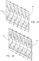
- FIGURE 21 shows a perspective view of a portion of one of the transition straps 80
- FIGURE 22 shows a perspective view of a portion of the back-to-back arrangement of two such straps 80.
- FIGURE 23 shows a side view of the back-to-back arrangement of straps 80 of FIGURE 22
- FIGURE 24 shows an overhead view (or a view from below) of the back-to-back arrangement of straps 80.
- This arrangement provides better structural support (eight-contact rather than seven-contact, i.e. no "missing" springs) to the fuel rods in the middle rows of the array and may improve grid impact strength.
- the spring lead-in formations on the doubled straps would typically be made shallower than the standard spring lead-in formations on the other interior grid straps in order to accommodate the extra thickness of the two back-to-back straps, thus requiring unique forming dies for these straps.
- FIGURES 25-27 another option for replacing either the alternating-spring transition strap configuration ( FIGURE 10 ) or the double transition strap configuration ( FIGURES 21-24 ) is to have a (single) transition strap 90 with two sets of dimples 44 1 , 44 2 facing in opposite directions.
- FIGURE 25 shows a perspective view of a portion of the transition strap 90
- FIGURE 26 shows a side view of the transition strap 90
- FIGURE 27 shows an overhead view (or a view from below) of the strap 90.
- the transition strap 90 thus includes twice as many dimples as an ordinary (i.e., non-transition) interior strap.
- both sets of dimples 44 1 , 44 2 can be formed from a single metal strip and would have the same contours as the dimples 44 of the existing interior strap 40 (see FIGURES 3 , 8, and 9 ), this alternative avoids the need for a unique die and does not introduce the same magnitude of flow diversion as the double transition strap design of FIGURES 21-24 .
- a down-side of the strap 90 is that it requires spring cutouts on the outer straps, which could potentially weaken the mid-grids and decrease their impact strength. Also, additional cutouts on the outer strap provide potential grid-to-grid hang-up locations during fuel handling.
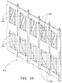
- FIGURE 28 shows a perspective view of a portion of the transition strap 100
- FIGURE 29 shows a side view of the transition strap 100
- FIGURE 30 shows an overhead view (or a view from below) of the strap 100.
- the orientation of the springs 146 1 , 146 2 in any given cell alternates such that the thick root of the upper spring 146 1 is positioned vertically above the thin hook on the lower spring 146 2 , thereby allowing the dual springs to be "nested" into less strap "real estate" than would otherwise be required.
- the transition strap 100 thus includes twice as many springs as an ordinary (i.e., non-transition) interior strap.
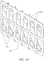
- FIGURE 31 shows a perspective view of a portion of the transition strap 200
- FIGURE 32 shows a side view of the transition strap 200
- FIGURE 33 shows an overhead view (or a view from below) of the strap 200.
- This design is a variation on the dual vertical spring design in which the two vertical cantilever spring features 246 1 , 246 2 are arranged side by side on the transition strap 200.
- Each spring 246 1 , 246 2 is tapered and formed similar to the springs 46 of the interior strap 40 (see FIGURES 3 , 8, and 9 ).
- the transition strap 200 includes twice as many springs as an ordinary (i.e., non-transition) interior strap.
- a transition strap 300 is similar to the design of FIGURE 10 in that it omits some springs.
- the transition strap 300 has a reversed-orientation dual vertical cantilever spring design with springs 346 1 , 346 2 .
- FIGURE 34 shows a perspective view of a portion of the transition strap 300
- FIGURE 35 shows a side view of the transition strap 300
- FIGURE 36 shows an overhead view (or a view from below) of the strap 300.
- This variation on the dual vertical spring design differs in that the springs 346 1 , 346 2 are stacked hook-to-hook rather than base-to-base resulting in a fuel rod contact geometry more like the conventional six-contact cell geometry in which the spring features grip the fuel rod at approximately the mid-elevation between the opposing dimples.
- This conventional loading arrangement creates a local bending moment at every spacer grid that can contribute to in-reactor fuel rod bow.
- the hook-to-hook spring orientation induces unbalanced twisting moments on the interior grid straps that are undesirable.
- the transition strap 300 one half of the springs face in one direction and the other half of the springs face in the opposite direction.
- the springs 46, 46 1 , 46 2 , 146 1 , 146 2 , 246 1 , 246 2 , 346 1 , 346 2 of the spacer grid have a lower spring constant (i.e. are less stiff) while the dimples 44, 44 1 , 44 2 have a higher spring constant (i.e. are more stiff).
- the springs have a spring constant that is no larger than one-half of the spring constant of the dimples.
- the springs have a spring constant of 500 pounds/inch or less while the dimples have a spring constant of 1000 pounds/inch or higher.
- other spring constants and/or spring constant ratios are contemplated.
Landscapes
- Physics & Mathematics (AREA)
- Engineering & Computer Science (AREA)
- Plasma & Fusion (AREA)
- General Engineering & Computer Science (AREA)
- High Energy & Nuclear Physics (AREA)
- Chemical & Material Sciences (AREA)
- Chemical Kinetics & Catalysis (AREA)
- Fuel Cell (AREA)
- Springs (AREA)
Description
- This application claims the benefit of
U.S. Provisional Application No. 61/625,130 filed April 17, 2012 - The following relates to the nuclear fuel arts, nuclear reactor arts, nuclear power generation arts, and related arts.
- A nuclear reactor core is typically constructed as an array of fuel assemblies (FA's) in which each FA is vertically coextensive with the height of the reactor core and the array of FA's spans the lateral dimensions of the reactor core. Each FA comprises an array of vertically oriented fuel rods held together by a structural skeleton comprising a set of horizontal spacer grids spaced apart along the vertical direction which are welded to guide tubes or other rod-like vertical elements. The upper and lower ends of the FA are capped by upper and lower end fittings (also sometimes called nozzles) connected to the guide tubes by fasteners, welding, or the like.
- Conventional spacer grids are constructed by interlocking straps, where each strap is machined (e.g. stamped) from a strip of metal, such as a nickel-chromium alloy (e.g., Inconel™) strip or a zirconium alloy (e.g., Zircaloy™) strip. The intersecting straps define openings, also called cells, through which fuel rods pass. The straps may be machined or stamped to define dimples (i.e., "hard" stops, protrusions having high stiffness) and springs (i.e. "soft" stops, protrusions having low stiffness) in each cell to hold the fuel rod passing through the cell. Typically two dimples are formed from the straps forming two adjacent walls in each square cell. One dimple in each pair is located near the top of the grid strap and the other is located near the bottom of the grid strap. The opposite cell walls each contain a single spring which may either be formed from the strap that makes that cell wall, or in the case of a bi-metallic spacer grid, may be an insert made of a different material that is mechanically trapped or restrained by features formed from the strap that make up that cell wall. The springs are located at or near the mid-plane of the spacer grid, and are sized so that an interference condition exists when a fuel rod is inserted into the grid cell. This interference causes the springs to deflect backwards towards the cell walls on which they are located, preloading the fuel rod in two orthogonal directions against the opposing dimple pair and clamping it in position. The axial offset between the plane of action of the springs and the plane of action of the dimples creates restoring moments that cause the local vertical orientation of the fuel rod at the spacer grids to remain relatively fixed should lateral forces be applied to the fuel rod between any two axially adjacent spacer grids.
- The straps in a conventional spacer grid are typically oriented such that the springs in a given cell are on the outboard cell wall and the dimples are on the inboard cell wall. This arrangement has the advantage of providing a more rigid foundation to resist any inward-acting forces that may be applied to the outer row of fuel rods should the fuel assembly contact a neighboring fuel assembly or other adjacent structure during handling. However, because this conventional arrangement requires that the outer strap contain springs in each grid cell, it also results in a significant weakening of those straps which can adversely impact the strength of the overall spacer grid structure. In some conventional spacer grids this weakness is at least partially compensated by using a thicker outer strap and/or via stiffening ribs and other mechanical features. However, this approach results in the outer strap springs having different (typically higher) spring rates than the interior strap springs which can lead to in-service fuel rod bow in the outer row of the fuel rod array.
- The following discloses various improvements.
- In the embodiments, a spacer grid includes a plurality of intersecting straps having springs and dimples formed into the straps, the intersecting straps defining cells with the springs and dimples arranged to engage fuel rods passing through the cells. The direction of the springs switches at a switch point in the spacer grid that is not at the center of the spacer grid. The intersecting straps include (i) a first set of mutually parallel straps including a first transition strap and (ii) a second set of mutually parallel straps including a second transition strap, the second set of mutually parallel straps intersecting the first set of mutually parallel straps, the intersection of the first transition strap and the second transition strap defining the switch point in the spacer grid that is not at the center of the spacer grid. The switch point in the spacer grid is spaced apart from the center of the spacer grid by at least two cells.
- In accordance with another aspect, a spacer grid includes intersecting straps having springs and dimples formed into the straps, the intersecting straps defining cells with the springs and dimples arranged to hold fuel rods passing through the cells. The intersecting straps include a first set of mutually parallel straps including a first transition strap, and a second set of mutually parallel straps including a second transition strap. The second set of mutually parallel straps intersects the first set of mutually parallel straps. The first transition strap and the second transition strap are interior straps of the spacer grid. In some embodiments, springs formed into the first set of mutually parallel straps other than the first transition strap face away from the first transition strap, springs formed into the second set of mutually parallel straps other than the second transition strap face away from the second transition strap, dimples formed into the first set of mutually parallel straps other than the first transition strap face toward the first transition strap, and dimples formed into the second set of mutually parallel straps other than the second transition strap face toward the second transition strap. In some embodiments springs are formed into the first and second transition straps but dimples are not formed into the first and second transition straps. In some embodiments dimples are formed into the outer straps of the spacer grid but springs are not formed into the outer straps of the spacer grid. The first transition strap may include two back-to-back straps with springs facing outward, and the second transition strap may include two back-to-back straps with springs facing outward. Alternatively, each of the first and second transition straps may be a single transition strap that includes twice as many springs as any other (non-transition) strap with the springs formed into the first transition strap defining two groups of springs facing in opposite directions.
- In accordance with another aspect, a spacer grid including intersecting straps having springs and dimples formed into the straps, the intersecting straps defining cells with the springs and dimples arranged to hold fuel rods passing through the cells, the outer straps of the spacer grid including dimples but not including springs.
- The invention may take form in various components and arrangements of components, and in various process operations and arrangements of process operations. The drawings are only for purposes of illustrating preferred embodiments and are not to be construed as limiting the invention.
-
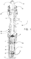
FIGURE 1 diagrammatically shows a perspective partial sectional view of an illustrative nuclear reactor of the pressurized water reactor (PWR) variety with internal steam generators (integral PWR). -
FIGURE 2 diagrammatically shows a perspective view of one of the fuel assemblies of the nuclear reactor core of the nuclear reactor ofFIGURE 1 . -
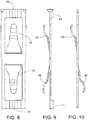
FIGURES 3-9 diagrammatically show one of the spacer grids of the fuel assembly ofFIGURE 2 , where:FIGURE 3 shows a side view of an interior strap;FIGURE 4 shows a perspective view of the spacer grid;FIGURE 5 shows a side view of an outer strap;FIGURES 6 and 7 show alternative spring contact surface designs; andFIGURES 8 and 9 show front and side views respectively of a dual cantilever spring/dimples contacting structure of an interior strap. -
FIGURE 10 shows a side view of a transition strap with an "S"-shaped dual cantilever spring configuration. -
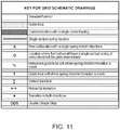
FIGURE 11 shows a key defining symbols and representations used in the drawings in depicting diagrammatic overhead views of spacer grid embodiments. -
FIGURE 12 shows a diagrammatic overhead view of a baseline spacer grid embodiment. -
FIGURE 13 shows a table comparing the baseline grid design ofFIGURE 12 with seven alternative designs. -
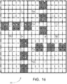
FIGURES 14-20 shows diagrammatic overhead views of the seven alternative spacer grid embodiments tabulated in the table ofFIGURE 13 . -
FIGURES 21-24 show an alternative transition strap design comprising back-to-back straps. -
FIGURES 25-27 show an alternative transition strap design including a doubled set of dimples. -
FIGURES 28-30 show an alternative transition strap design employing an alternative spring configuration. -
FIGURES 31-33 show another alternative transition strap design employing an alternative spring configuration. -
FIGURES 34-36 show another alternative transition strap design employing an alternative spring configuration. - With reference to
FIGURE 1 , an illustrativenuclear reactor 1 of the pressurized water reactor (PWR) variety is shown. Theillustrative PWR 1 includes anuclear reactor core 2 disposed in a pressure vessel which in the illustrative embodiment comprises alower vessel portion 3 and anupper vessel portion 4 connected by a mid-flange 5. Thereactor core 2 is disposed in thelower vessel portion 3, and comprises a fissile material (e.g., 235U) immersed in primary coolant water. A cylindricalcentral riser 6 is disposed coaxially inside the cylindrical pressure vessel and a downcomer annulus 7 is defined between thecentral riser 6 and the pressure vessel. Theillustrative PWR 1 includes internal control rod drive mechanisms (internal CRDMs) 8 that control insertion of control rods to control reactivity; however, the reactor can alternatively employ external CRDMs. In either case, guide frame supports 9 guide the translating control rod assembly (e.g., each including a set of control rods comprising neutron absorbing material yoked together by a spider and connected via a connecting rod with the CRDM). Theillustrative PWR 1 employsinternal steam generators 10 located inside the pressure vessel, but embodiments with the steam generators located outside the pressure vessel (i.e., a PWR with external steam generators) are also contemplated. Theillustrative steam generators 10 are of the once-through straight-tube type with internal economizer, and are fed by afeedwater inlet 11 and deliver steam to asteam outlet 12. Theillustrative PWR 1 includes anintegral pressurizer 14 at the top of theupper vessel section 4 which defines anintegral pressurizer volume 15; however an external pressurizer connected with the pressure vessel via suitable piping is also contemplated. The primary coolant in theillustrative PWR 1 is circulated by reactor coolant pumps (RCPs) comprising in the illustrative exampleexternal RCP motors 16 driving an impeller located in aRCP casing 17 disposed inside the pressure vessel. Theillustrative PWR 1 also includes anoptional support skirt 18. It is to be appreciated that thePWR 1 is merely an illustrative example - the disclosed spacer grids and fuel assemblies including same are suitably employed in substantially any type of PWR as well as in nuclear reactors of other types such as boiling water reactor (BWR) designs. - With reference to
FIGURE 2 , arepresentative fuel assembly 20 is diagrammatically shown with partial breakaway and the front top corner of the perspective view cut away to reveal internal components. Thefuel assembly 20 is suitably employed as an element of thenuclear reactor core 2 disposed in the pressure vessel ofFIGURE 1 . Thefuel assembly 20 includes an array of vertically orientedfuel rods 22 each comprising a fissile material such as 235U. For example, each fuel rod may contain enriched uranium dioxide (UO2) or mixed UO2/gadolinium oxide (UO2-Gd2O3) pellets. Interspersed amongst thefuel rods 20 areguide tubes 24 that provide conduits for control rods, instrumentation, or so forth. The top of thefuel assembly 20 is terminated by an upper end fitting ornozzle 26 and the bottom of thefuel assembly 20 is terminated by a lower end fitting ornozzle 28. The vertical direction of thefuel assembly 20 is denoted as the vertical or "elevation" direction E inFIGURE 2 . - The
fuel assembly 20 is held together by a plurality of spacer grids includingend grids 30 disposed near the top and bottom of thefuel assembly 20 and one or (typically) more mid-grids 32 disposed at spaced apart positions between the top and bottom of thefuel assembly 20. (Said another way, eachend spacer grid 30 is closer to an end of the bundle offuel rods 22 than the mid-grid 32). IllustrativeFIGURE 2 shows only twomid-grids 32, but typically additional mid-grids are present which are omitted in the cutaway illustration. The number of mid-grids, and the spacing of the end grids and mid grids along the height of the fuel assembly, is determined based on the total length of the bundle of fuel rods, the total number of fuel rods in the bundle, the structural characteristics of the fuel rods, applicable regulatory requirements, and so forth. As indicated diagrammatically inFIGURE 1 , thegrids grids end grids 30 are made of Inconel while the mid-grids 32 are made of Zircaloy. - With reference to
FIGURES 3-5 , some design features of some illustrative spacer grids disclosed herein are shown.FIGURE 4 shows a perspective view of an illustrative spacer grid 31 (where thegrid 31 may in general serve as either one of theend grids 30 or one of the mid-grids 32 shown inFIGURE 2 ).FIGURE 3 shows aninterior strap 40 of thegrid 31, whileFIGURE 5 shows anouter strap 42 of thegrid 31. Each standard cell defined by intersecting interior straps contains horizontally oriented dimple features (or stops) 44 at the top and bottom edges sandwiched around a pair of vertically-oriented cantilever spring features 46. The cantilever spring features 46, which are designed to have a large elastic deflection range compared with thedimples 44, are formed with their main surfaces inclined relative to the remainder of the vertical cell wall so as to create a substantial interference with the fuel rod. When the fuel rod is inserted into the fuel assembly during manufacturing, these dual spring features 46 are deflected back towards the vertical cell wall, creating a clamping force that pins the fuel rod against the opposingdimple pair 44. This same clamping action is simultaneously actuated at 90 degrees around the cladding by the spring and dimple features in the perpendicular cell walls. The outer straps 42 on theillustrative spacer grids 31 contain dimple features 44 only. This configuration has an advantage over grid designs that have spring features on the outer straps in that the material cutouts on the outer strap are minimized, enhancing the structural strength of the outer straps. - The spring and dimple features are replaced in the guide tube cells with saddle features that position the control rod guide tubes accurately without generating any appreciable clamping force. Rather, the guide tubes are welded to the
grids 31 to form (optionally along with thenozzles 26, 28) the structural skeleton of thefuel assembly 20. Optional integral tabs on the top and bottom edges of the interior grid straps in these special cells (not shown) are used to attach the mid-grids 32 to the control rod guide tubes permanently during fuel assembly manufacturing. - With reference to
FIGURES 6 and 7 , the contact surfaces of thesprings 46 of theinterior straps 40 can have various shapes. In choosing the shape of the contact surfaces, factors such as fuel rod lead-in, ductility or brittleness of the material, and so forth are suitably taken into account. For example, if the end-grids 30 are made of Inconel, which is relatively ductile, the contact surfaces can be shaped as flat-toppeddomes 50 to provide good lead-in/fuel rod engagement surfaces for the springs. On the other hand, if the mid-grids 32 are made of more brittle Zircaloy, then the contact surfaces can be shaped as more simple-to-manufacture hooks 52 formed by bending the free ends of the springs as to include a flat rod engagement portion and a distal "bent-back" portion that facilitates lead-in. - To avoid having springs in the
outer straps 42, all of thesprings 46 in this grid design face from the center of the grid outward. Accordingly, there is a transition point or points in the grid where the spring direction reverses. In the baseline grid design, this spring direction transition occurs near the center of the grid. - With reference to
FIGURES 8 and 9 , a single fuel rod engagement portion is shown in front profile and side profile respectively, illustrating thedimples 44 and springs 46. Note that thedimples 44 shown inFIGURES 8 and 9 engage one cell (namely the cell "behind" inFIGURE 8 or "to the right" inFIGURE 9 ) while thesprings 46 engage another cell (namely the cell "in front" inFIGURE 8 or "to the left" inFIGURE 9 ). - In the embodiments, spacer grid 31 (
FIGURE 4 ) includes a plurality of intersectingstraps springs 46 anddimples 44 ofFIGURES 8 and/or 9 formed into the straps. The intersecting straps 40, 42 define cells with the springs and dimples arranged to engage (i.e., hold) fuel rods passing through the cells. The intersecting straps 40, 42 include (i) a first set of mutually parallel straps including a first transition strap and (ii) a second set of mutually parallel straps including a second transition strap, the second set of mutually parallel straps intersecting the first set of mutually parallel straps. Thesprings 46 formed into theinterior straps 40 of the first set of mutually parallel straps (other than the first transition strap) face away from the first transition strap, and thesprings 46 formed into theinterior straps 40 of the second set of mutually parallel straps (other than the second transition strap) face away from the second transition strap. Similarly, thedimples 44 formed into the straps of the first set of mutually parallel straps (other than the first transition strap) face toward the first transition strap and thedimples 44 formed into the straps of the second set of mutually parallel straps (other than the second transition strap) face toward the second transition strap. - With reference to
FIGURE 10 , to utilize two grid transition straps to make the transition (one in each direction orthogonal to each other, i.e. the aforementioned first transition strap and second transition strap), the dual contact cantilever spring ofFIGURES 8 and 9 is replaced in the transition straps with an "S" shaped, single contact spring configuration shown inFIGURE 10 in which the directions of the upper andlower springs 46 are reversed. Additionally, there is no need for thedimples 44 on the grid straps ofFIGURE 10 as at the transition both sides engage the proximate fuel rods via thesprings 46. In the transition strap ofFIGURE 10 , one half of the springs face in one direction and the other half of the springs face in the opposite direction. - With reference to
FIGURE 11 , in the grid design examples described herein are illustrated inFIGURES 12 and following as diagrammatic overhead views using lines to represent straps viewed "on edge" from above (or below) the grid. Symbolic representations (e.g., hatching, cell labeling, line types, et cetera) shown in the key ofFIGURE 11 are used to identify relevant features such as guide tube locations, various types of fuel rod locations (differentiated based on number of springs), transition regions where springs transition from facing one direction to the opposite direction, and so forth. Cells designated for guide tubes are also labeled (where appropriate) to indicate transitions using the letter "T" along with a double-headed arrow indicating the transition direction, as defined inFIGURE 11 . Any of the grids design examples described herein may serve as thegrid 31 ofFIGURES 3-5 , and may more particularly serve as the design for the end-grids 30 ormid-grids 32 ofFIGURE 2 . In the examples ofFIGURES 12 and forward, it is assumed that the strap ofFIGURE 10 is employed at transitions so that some cells have missing springs (the number of missing springs in the cell being indicated by symbols defined in the key ofFIGURE 11 ). As set forth in the examples ofFIGURES 12 and following, by appropriate grid design the number of missing springs for any given cell along the transitions can be managed. - With reference to
FIGURE 12 , abaseline grid design 60 is shown. In this design, some fuel rod cells at the transitions have single contact springs in one direction and double contact springs in the orthogonal direction. Since the ideal configuration is a fuel rod cell with dual contact springs in both directions, adjacent grids on the fuel assembly (in the vertical or "elevation" direction E denoted inFIGURE 2 ) are preferably rotated by 90 degrees relative to each other to decrease the number of fuel rods that have single contact springs at every grid elevation. Despite the grid rotations, there will still be a limited number of fuel rod cells in thefuel assembly 20 that have a single contact spring in at least one direction at every grid elevation. These locations are marked with a "O" inFIGURE 12 (see key ofFIGURE 11 ). Four fuel rod cells near the center of thebaseline grid 60 have single contact springs in both directions. These locations are marked with a "X". Again, rotating adjacent grids along the fuel assembly length will minimize the number of fuel rods that have single contact springs in both directions. However, the center fuel rod cell will have single contact springs in both directions along the full length of the fuel assembly. This cell is marked with a "%". - The dual cantilever spring arrangement described with reference to
FIGURES 8-9 combined with the near-alignment of the planes of action of thesprings 46 with the planes of actions of the opposingdimples 44 minimizes the induced fuel rod bow. Eliminating the spring cutouts on the outer straps 42 (FIGURE 5 ) makes for a much stronger spacer grid during lateral impacts. The disclosedgrid design 60 also minimizes the number of different types of straps are required to make thegrid 60 and keeps the number of single spring contacts to a minimum. In an alternative approach, to reduce the number of single spring contacts additional strap types could be added. - With reference to
FIGURE 13 and following, some alternative grid designs are disclosed.FIGURE 13 tabulates the illustrative alternative grid designs whileFIGURES 14-20 diagrammatically illustrate these alternative designs using the notation defined inFIGURE 11 . The disclosed alternatives to the baselinespacer grid design 60 ofFIGURE 12 can be divided into two categories. The first category, referred to as "Category 1", are tabulated inFIGURE 13 and shown by diagrammatic example inFIGURES 14-20 . These include grid design alternatives that maintain the basic spring and dimple design but change the arrangement of these features within the grid. - A second category of alternatives, referred to as "
Category 2", includes changes to the basic spring geometry and changes to the baseline spacer grid structural arrangement as described with reference toFIGURES 21 and forward. - Some of the alternate grid designs provide improvements over the
grid design 60 ofFIGURE 12 but at the expense of increased complexity. This increased complexity may not be desirable for a manual forming operation. However, a production Computer Numerical Control (CNC) stamping operation is contemplated for manufacturing the grid straps, and CNC manufacturing would be relatively immune to the increased complexity. - With continuing reference to
FIGURES 13-20 , theCategory 1 grid design alternatives include design alternatives where guide tube cells are utilized to make spring reversals. Making spring reversals at guide tube locations advantageously minimizes the number of fuel rod cells that have single contact springs, but also increases the number of strap types that are required to make a complete grid. The disclosedCategory 1 alternatives also include designs that move the single contact spring transition away from the center of the grid to take advantage of adjacent grid rotations to minimize the number of fuel rod cells that have single contact springs along the full length of the fuel assembly. The disclosedCategory 1 alternatives are described in the following with reference to the diagrammatic grid representations ofFIGURES 14-20 , and are compared to each other in the Table ofFIGURE 13 . - With reference to
FIGURE 14 , agrid design 62 is diagrammatically shown which is referred to herein as the "Offset Single Contact Spring Strap" design (called the "Offset" design inFIGURE 13 ). The OffsetSpring Configuration 62 ofFIGURE 14 takes thebaseline design 60 ofFIGURE 12 and shifts the transition over a couple straps away from center. An advantage ofgrid design 62 is that it reduces the number of single contact spring cell locations that are repeated on vertically adjacent grids. - With reference to
FIGURE 15 , agrid design 64 is diagrammatically shown which is referred to herein as the "Offset-2 Single Contact Spring Strap" design (called the "Offset-2" design inFIGURE 13 . The Offset-2grid design 64 is similar to the Offsetgrid design 62 ofFIGURE 14 except that the guide tube locations are employed to make the spring direction reversal. The Offset-2grid 64 adds complexity but further reduces the number of fuel rod cells with single contact springs. - With reference to
FIGURE 16 , agrid design 66 is diagrammatically shown which is referred to herein as the "Pinwheel Single Contact Spring Strap" design (called the "Pinwheel" design inFIGURE 13 ). ThePinwheel grid design 66 provides a more uniform distribution of the single contact springs and reduces the number of fuel rod cells with single contact springs. ThePinwheel design 66 increases the number of fuel rod cells with single contact springs on adjacent grids. - With reference to
FIGURE 17 , agrid design 68 is diagrammatically shown which is referred to herein as the "Staggered-1 Single Contact Spring Strap" design (called the "Staggered-1" design inFIGURE 13 ). The Staggered-1grid design 68 attempts to distribute the single contact fuel rod cells evenly throughout the grid. While this design reduces the number of single contact springs, the number of different grid strap designs required to make a grid goes up by three. - With reference to
FIGURE 18 , agrid design 70 is diagrammatically shown which is referred to herein as the "Staggered-2 Single Contact Spring Strap" design (called the "Staggered-2" design inFIGURE 13 ). The Staggered-2grid design 70 is a variation of the Staggered-1grid design 68 ofFIGURE 17 . While this design reduces the number of single contact springs, the number of different grid strap designs required to make a grid goes up by three. - With reference to
FIGURE 19 , agrid design 72 is diagrammatically shown which is referred to herein as the "Staggered-3 Single Contact Spring Strap" design (called the "Staggered-3" design inFIGURE 13 ). The Staggered-3grid design 72 is another variation of the Staggered-1grid design 68 ofFIGURE 17 . Advantages of thegrid design 72 are that it reduces the number of fuel rod cells containing one single contact spring and only adds one additional grid strap design required to make the grid. However, a disadvantage of thegrid design 72 is that it adds four additional fuel rods cells for which there are two single contact springs. - With reference to
FIGURE 20 , agrid design 74 is diagrammatically shown which is referred to herein as the "Staggered-4 Single Contact Spring Strap" design (called the "Staggered-4" design inFIGURE 13 ). The Staggered-4grid design 74 is another variation of the Staggered-1grid design 68 ofFIGURE 17 . Thegrid design 74 reduces the number of single contact springs and eliminates single contact spring locations on adjacent grids. This design does add complexity and increases the required number of grid straps to fabricate a grid by one. - With reference to
FIGURES 21 and following, theCategory 2 grid design alternatives are next described. TheCategory 2 grid designs include changes to the spring geometry at the transitions, and changes to the baseline spacer grid structural arrangement (e.g., changes to thebaseline design 60 ofFIGURE 12 ). TheCategory 2 alternatives are described below. - With reference to
FIGURES 21-24 , an alternative design of theCategory 2 variety employing a back-to-back double strap design is described. In this design the modified transition strap described with reference toFIGURE 10 is replaced by a "back-to-back" strap design in which two all-spring (no dimple)interior straps 80 are arranged in a back-to-back configuration. Eachstrap 80 includes thesprings 46 of the conventional interior strap 40 (seeFIGURES 3 ,8, and 9 ) but omits thedimples 44.FIGURE 21 shows a perspective view of a portion of one of the transition straps 80, whileFIGURE 22 shows a perspective view of a portion of the back-to-back arrangement of twosuch straps 80.FIGURE 23 shows a side view of the back-to-back arrangement ofstraps 80 ofFIGURE 22 , whileFIGURE 24 shows an overhead view (or a view from below) of the back-to-back arrangement ofstraps 80. This arrangement provides better structural support (eight-contact rather than seven-contact, i.e. no "missing" springs) to the fuel rods in the middle rows of the array and may improve grid impact strength. The spring lead-in formations on the doubled straps would typically be made shallower than the standard spring lead-in formations on the other interior grid straps in order to accommodate the extra thickness of the two back-to-back straps, thus requiring unique forming dies for these straps. - With reference to
FIGURES 25-27 , another option for replacing either the alternating-spring transition strap configuration (FIGURE 10 ) or the double transition strap configuration (FIGURES 21-24 ) is to have a (single)transition strap 90 with two sets ofdimples FIGURE 25 shows a perspective view of a portion of thetransition strap 90,FIGURE 26 shows a side view of thetransition strap 90, andFIGURE 27 shows an overhead view (or a view from below) of thestrap 90. Thetransition strap 90 thus includes twice as many dimples as an ordinary (i.e., non-transition) interior strap. Since both sets ofdimples dimples 44 of the existing interior strap 40 (seeFIGURES 3 ,8, and 9 ), this alternative avoids the need for a unique die and does not introduce the same magnitude of flow diversion as the double transition strap design ofFIGURES 21-24 . A down-side of thestrap 90 is that it requires spring cutouts on the outer straps, which could potentially weaken the mid-grids and decrease their impact strength. Also, additional cutouts on the outer strap provide potential grid-to-grid hang-up locations during fuel handling. - With reference to
FIGURES 28-30 , atransition strap 100 with a dual horizontal nested cantilever spring design is described. Thestrap 100 includes two horizontal cantilever spring features 1461 , 1462 arranged one above the other on thestrap 100.FIGURE 28 shows a perspective view of a portion of thetransition strap 100,FIGURE 29 shows a side view of thetransition strap 100, andFIGURE 30 shows an overhead view (or a view from below) of thestrap 100. The orientation of the springs 1461, 1462 in any given cell alternates such that the thick root of the upper spring 1461 is positioned vertically above the thin hook on the lower spring 1462 , thereby allowing the dual springs to be "nested" into less strap "real estate" than would otherwise be required. This vertical stacking of the springs 1461, 1462 is reversed from cell to cell to balance the twisting moments applied to the interior grid straps. Thetransition strap 100 thus includes twice as many springs as an ordinary (i.e., non-transition) interior strap. - With reference to
FIGURES 31-33 , atransition strap 200 with side-by-side nested vertical cantilever springs 2461, 2462 is described.FIGURE 31 shows a perspective view of a portion of thetransition strap 200,FIGURE 32 shows a side view of thetransition strap 200, andFIGURE 33 shows an overhead view (or a view from below) of thestrap 200. This design is a variation on the dual vertical spring design in which the two vertical cantilever spring features 2461, 2462 are arranged side by side on thetransition strap 200. Eachspring springs 46 of the interior strap 40 (seeFIGURES 3 ,8, and 9 ). The orientation of the twosprings transition strap 100, thetransition strap 200 includes twice as many springs as an ordinary (i.e., non-transition) interior strap. - With reference to
FIGURES 34-36 , atransition strap 300 is similar to the design ofFIGURE 10 in that it omits some springs. Thetransition strap 300 has a reversed-orientation dual vertical cantilever spring design with springs 3461, 3462.FIGURE 34 shows a perspective view of a portion of thetransition strap 300,FIGURE 35 shows a side view of thetransition strap 300, andFIGURE 36 shows an overhead view (or a view from below) of thestrap 300. This variation on the dual vertical spring design differs in that the springs 3461, 3462 are stacked hook-to-hook rather than base-to-base resulting in a fuel rod contact geometry more like the conventional six-contact cell geometry in which the spring features grip the fuel rod at approximately the mid-elevation between the opposing dimples. This conventional loading arrangement creates a local bending moment at every spacer grid that can contribute to in-reactor fuel rod bow. In addition, the hook-to-hook spring orientation induces unbalanced twisting moments on the interior grid straps that are undesirable. Like the transition strap ofFIGURE 10 , in thetransition strap 300 one half of the springs face in one direction and the other half of the springs face in the opposite direction. - In the foregoing spacer grid designs, the
springs dimples - The preferred embodiments have been illustrated and described. Obviously, modifications and alterations will occur to others upon reading and understanding the preceding detailed description. It is intended that the invention be construed as including all such modifications and alterations insofar as they come within the scope of the appended claims.
Claims (17)
- An apparatus comprising:a spacer grid (31) including a plurality of intersecting straps (40, 42) having springs (46) and dimples (44) formed into the straps, the intersecting straps defining cells with the springs and dimples arranged to engage fuel rods (22) passing through the cells;wherein the direction of the springs switches at a switch point in the spacer grid that is not at the center of the spacer grid; wherein the intersecting straps include (i) a first set of mutually parallel straps including a first transition strap and (ii) a second set of mutually parallel straps including a second transition strap, the second set of mutually parallel straps intersecting the first set of mutually parallel straps, the intersection of the first transition strap and the second transition strap defining the switch point, characterised in that the switch point is spaced apart from the center of the spacer grid by at least two cells.
- The apparatus of claim 1 wherein the springs formed into the straps of the first set of mutually parallel straps other than the first transition strap face away from the first transition strap and the springs formed into the straps of the second set of mutually parallel straps other than the second transition strap face away from the second transition strap.
- The apparatus of claim 2 wherein the dimples formed into the straps of the first set of mutually parallel straps other than the first transition strap face toward the first transition strap and the dimples formed into the straps of the second set of mutually parallel straps other than the second transition strap face toward the second transition strap.
- The apparatus of claim 3 wherein either:the first transition strap does not include dimples and the second transition strap does not include dimples; or the outer straps of the plurality of intersecting straps include dimples but do not include springs; or the first transition strap includes two back-to-back straps with outwardly facing springs and the second transition strap includes two back-to-back straps with outwardly facing springs.
- The apparatus of claim 3 wherein:one half of the springs of the first transition strap face in one direction and the other half of the springs of the first transition strap face in the opposite direction; andone half of the springs of the second transition strap face in one direction and the other half of the springs of the second transition strap face in the opposite direction.
- A fuel assembly comprising fuel rods comprising fissile material held in a spaced apart arrangement by spacer grids set forth in claim 1.
- A nuclear reactor comprising a pressure vessel containing a nuclear reactor core wherein the nuclear reactor core includes fuel rods comprising fissile material held in a spaced apart arrangement by spacer grids set forth in claim 1.
- The apparatus of claim 1
wherein the first transition strap and the second transition strap are interior straps of the spacer grid, the springs formed into the first set of mutually parallel straps other than the first transition strap facing away from the first transition strap, the springs formed into the second set of mutually parallel straps other than the second transition strap facing away from the second transition strap, the dimples formed into the first set of mutually parallel straps other than the first transition strap facing toward the first transition strap, the dimples formed into the second set of mutually parallel straps other than the second transition strap facing toward the second transition strap. - The apparatus of claim 8 wherein:springs are formed into the first transition strap,springs are formed into the second transition strap,dimples are not formed into the first transition strap, anddimples are not formed into the second transition strap, optionally wherein:springs are not formed into the outer straps of the spacer grid, anddimples are formed into the outer straps of the spacer grid
- The apparatus of claim 8 wherein:springs are not formed into the outer straps of the spacer grid, anddimples are formed into the outer straps of the spacer grid
- The apparatus of claim 8 wherein:one half of the springs formed into the first transition strap face in one direction and the other half of the springs formed into the first transition strap face in the opposite direction; andone half of the springs formed into the second transition strap face in one direction and the other half of the springs formed into the second transition strap face in the opposite direction.
- The apparatus of claim 8 wherein:the first transition strap includes a first two back-to-back straps with springs formed into the first two back-to-back straps facing outward from the first two back-to-back straps, andthe second transition strap includes a second two back-to-back straps with springs formed into the second two back-to-back straps facing outward from the second two back-to-back straps.
- The apparatus of claim 8 wherein:the first transition strap includes twice as many springs as any other strap of the first set of mutually parallel straps with the springs formed into the first transition strap defining two groups of springs facing in opposite directions, andthe second transition strap includes twice as many springs as any other strap of the second set of mutually parallel straps with the springs formed into the second transition strap defining two groups of springs facing in opposite directions.
- The apparatus of claim 8 wherein:springs are not formed into the first transition strap,springs are not formed into the second transition strap,dimples are formed into the first transition strap, anddimples are formed into the second transition strap.
- The apparatus of claim 14 wherein:the first transition strap includes twice as many dimples as any other strap of the first set of mutually parallel straps with the dimples formed into the first transition strap defining two groups of dimples facing in opposite directions, andthe second transition strap includes twice as many dimples as any other strap of the second set of mutually parallel straps with the dimples formed into the second transition strap defining two groups of springs facing in opposite directions.
- The apparatus of claim 8 wherein the springs have a spring constant that is no larger than one-half of the spring constant of the dimples; or the springs are cantilevered springs.
- A fuel assembly comprising fuel rods comprising fissile material held in a spaced apart arrangement by spacer grids set forth in claim 8.
Applications Claiming Priority (3)
| Application Number | Priority Date | Filing Date | Title |
|---|---|---|---|
| US201261625130P | 2012-04-17 | 2012-04-17 | |
| US13/746,116 US9378852B2 (en) | 2012-04-17 | 2013-01-21 | Spacer grids for nuclear reactor |
| PCT/US2013/025055 WO2013162669A2 (en) | 2012-04-17 | 2013-02-07 | Spacer grids for nuclear reactor |
Publications (3)
| Publication Number | Publication Date |
|---|---|
| EP2839469A2 EP2839469A2 (en) | 2015-02-25 |
| EP2839469A4 EP2839469A4 (en) | 2016-04-06 |
| EP2839469B1 true EP2839469B1 (en) | 2017-09-06 |
Family
ID=49484013
Family Applications (1)
| Application Number | Title | Priority Date | Filing Date |
|---|---|---|---|
| EP13780970.3A Active EP2839469B1 (en) | 2012-04-17 | 2013-02-07 | Spacer grids for nuclear reactor |
Country Status (5)
| Country | Link |
|---|---|
| US (1) | US9378852B2 (en) |
| EP (1) | EP2839469B1 (en) |
| CN (1) | CN104520937A (en) |
| CA (1) | CA2870721C (en) |
| WO (1) | WO2013162669A2 (en) |
Families Citing this family (3)
| Publication number | Priority date | Publication date | Assignee | Title |
|---|---|---|---|---|
| RU2638647C2 (en) * | 2016-05-04 | 2017-12-15 | Публичное акционерное общество "Машиностроительный завод" | Mixing and spacer grids of nuclear reactor fuel assembly (versions) |
| CN105869681B (en) * | 2016-05-26 | 2018-03-20 | 中广核研究院有限公司 | Fuel assembly and its without outer band grid spacer and band |
| CN110164567B (en) * | 2018-03-30 | 2023-01-17 | 吉林农业大学 | A pressurized water reactor fuel assembly grid |
Family Cites Families (74)
| Publication number | Priority date | Publication date | Assignee | Title |
|---|---|---|---|---|
| US3679547A (en) * | 1968-12-16 | 1972-07-25 | Atomic Power Dev Ass Inc | Elastic support grid for nuclear fuel elements |
| US4426355A (en) | 1982-01-04 | 1984-01-17 | Combustion Engineering, Inc. | Spacer grid for nuclear fuel assembly |
| US4474730A (en) * | 1982-08-05 | 1984-10-02 | Westinghouse Electric Corp. | Nuclear fuel spacer grid |
| US4585615A (en) | 1983-03-09 | 1986-04-29 | Westinghouse Electric Corp. | Nuclear fuel spacer grid with improved grid straps |
| JPS63273090A (en) | 1987-04-30 | 1988-11-10 | Mitsubishi Nuclear Fuel Co Ltd | Support grid |
| US4803043A (en) | 1987-05-22 | 1989-02-07 | Westinghouse Electric Corp. | Nuclear fuel rod grid spring and dimple structures |
| JPH01173898A (en) | 1987-09-10 | 1989-07-10 | Mitsubishi Nuclear Fuel Co Ltd | Supporting grid of nuclear reactor fuel assembly |
| US4895698A (en) | 1988-03-14 | 1990-01-23 | Westinghouse Electric Corp. | Nuclear fuel rod grip with modified diagonal spring structures |
| DE3839838A1 (en) | 1988-11-25 | 1990-05-31 | Bbc Reaktor Gmbh | CORE INSTALLATION OF A WATER-COOLED CORE REACTOR |
| US4994233A (en) | 1989-01-27 | 1991-02-19 | Westinghouse Electric Corp. | Fuel rod with axial regions of annular and standard fuel pellets |
| US4990304A (en) | 1989-01-27 | 1991-02-05 | Westinghouse Electric Corp. | Instrumentation tube features for reduction of coolant flow-induced vibration of flux thimble tube |
| US4923669A (en) | 1989-02-21 | 1990-05-08 | Westinghouse Electric Corp. | Nuclear fuel rod grid spring and dimple structures having chamfered edges for reduced pressure drop |
| US4996018A (en) | 1989-04-19 | 1991-02-26 | Westinghouse Electric Corp. | High pressure thimble/guide tube seal fitting with built-in low pressure seal especially suitable for facilitated and more efficient nuclear reactor refueling service |
| US5043134A (en) | 1989-06-28 | 1991-08-27 | Westinghouse Electric Corp. | Fuel rod gripper end cap for minimizing impact with grid cell dimples |
| US4966745A (en) | 1989-06-28 | 1990-10-30 | Westinghouse Electric Company | Fuel rod gripper end cap for minimizing impact with grid cell dimples |
| US5024806A (en) | 1989-09-21 | 1991-06-18 | Westinghouse Electric Corp. | Enhanced debris filter bottom nozzle for a nuclear fuel assembly |
| US5009837A (en) | 1989-11-03 | 1991-04-23 | Westinghouse Electric Corp. | Axially modular fuel assembly and rod for optimal fuel utilization |
| US5068083A (en) | 1990-05-29 | 1991-11-26 | Westinghouse Electric Corp. | Dashpot construction for a nuclear reactor rod guide thimble |
| US5265137A (en) | 1990-11-26 | 1993-11-23 | Siemens Power Corporation | Wear resistant nuclear fuel assembly components |
| US5350161A (en) * | 1991-02-26 | 1994-09-27 | Combustion Engineering, Inc. | Nuclear reactor grid strip cantilever spring with nonuniform material characteristics |
| US5158740A (en) | 1991-08-05 | 1992-10-27 | Westinghouse Electric Corp. | Fuel rod end plug welding method |
| US5207980A (en) | 1991-10-27 | 1993-05-04 | Westinghouse Electric Corp. | Top nozzle-mounted replacement guide pin assemblies |
| US5268948A (en) | 1992-06-25 | 1993-12-07 | Duke Power Company | Locking assembly for nuclear fuel bundles |
| US5282231A (en) | 1992-09-23 | 1994-01-25 | Siemens Power Corporation | Lower tie plate cast frame |
| US5299246A (en) | 1992-09-25 | 1994-03-29 | Combustion Engineering, Inc. | Shape-memory alloys in the construction of nuclear fuel spacer grids |
| US5282233A (en) | 1992-09-28 | 1994-01-25 | Combustion Engineering, Inc. | Low pressure drop easy load end cap |
| US5367549A (en) | 1993-05-06 | 1994-11-22 | Combustion Engineering, Inc. | Hexagonal grid |
| US5436945A (en) | 1993-12-03 | 1995-07-25 | Combustion Engineering, Inc. | Shadow shielding |
| US5434898A (en) | 1994-03-14 | 1995-07-18 | Siemens Power Corporation | Nuclear fuel assembly |
| US5488644A (en) | 1994-07-13 | 1996-01-30 | General Electric Company | Spring assemblies for adjoining nuclear fuel rod containing ferrules and a spacer formed of the spring assemblies and ferrules |
| US5513234A (en) | 1994-07-18 | 1996-04-30 | Rottenberg; Sigmunt | Structural member for nuclear reactor pressure tubes |
| US5519747A (en) | 1994-10-04 | 1996-05-21 | General Electric Company | Apparatus and methods for fabricating spacers for a nuclear fuel rod bundle |
| US5566217A (en) | 1995-01-30 | 1996-10-15 | General Electric Company | Reduced height spacer for nuclear fuel rods |
| FR2736189B1 (en) | 1995-06-29 | 1997-09-26 | Framatome Sa | GRID SPACER OF A FUEL ASSEMBLY FOR A NUCLEAR REACTOR HAVING ADDED SPRINGS |
| US5640434A (en) | 1995-07-31 | 1997-06-17 | Rottenberg; Sigmunt | Miniaturized nuclear reactor utilizing improved pressure tube structural members |
| US5675621A (en) | 1995-08-17 | 1997-10-07 | General Electric Company | Reduced height flat spring spacer for nuclear fuel rods |
| SE508645C2 (en) | 1996-06-20 | 1998-10-26 | Asea Atom Ab | Nuclear fuel cartridge for light water reactor with axial gap in the fissile material |
| US5757874A (en) | 1996-07-10 | 1998-05-26 | General Electric Company | Multi-spring strip spacer for nuclear fuel bundles |
| JPH1123765A (en) | 1997-05-09 | 1999-01-29 | Toshiba Corp | Reactor core |
| FR2766003B1 (en) * | 1997-07-11 | 1999-12-03 | Framatome Sa | GRID FOR NUCLEAR FUEL ASSEMBLY AND PLATE FOR SUCH A GRID |
| KR100265027B1 (en) | 1997-12-12 | 2000-09-01 | 장인순 | Nozzle type mixing grid of nuclear fuel assembly |
| JPH11281784A (en) | 1998-03-26 | 1999-10-15 | Mitsubishi Heavy Ind Ltd | Control rod |
| US6055288A (en) | 1998-07-24 | 2000-04-25 | Westinghouse Electric Company | Nuclear reactor vessel |
| GB0000241D0 (en) | 2000-01-07 | 2000-03-01 | British Nuclear Fuels Plc | Improvements in and relating to nuclear fuel assemblies |
| JP2002122686A (en) | 2000-10-17 | 2002-04-26 | Toshiba Corp | Boiling water nuclear power plant and its construction method |
| EP1916667B1 (en) | 2001-04-05 | 2013-05-01 | Mitsubishi Heavy Industries, Ltd. | Fuel assembly and thimble screw of the same |
| FR2826172B1 (en) | 2001-06-14 | 2003-09-19 | Framatome Anp | METHOD AND APPARATUS FOR RESTORING THE FALL TIME OF AT LEAST ONE REACTIVITY CONTROL CLUSTER IN THE HEART OF A NUCLEAR REACTOR COOLED BY LIGHT WATER |
| US20030169839A1 (en) | 2002-03-11 | 2003-09-11 | Matteson Donn Moore | Prefabricated in-core instrumentation chase |
| US6895067B2 (en) | 2002-04-30 | 2005-05-17 | Framatome Anp, Inc. | Smooth collet for pulling fuel rods |
| US6819733B2 (en) | 2002-05-15 | 2004-11-16 | Westinghouse Electric Company Llc | Fuel assembly and associated grid for nuclear reactor |
| US6636578B1 (en) | 2002-06-05 | 2003-10-21 | Framatome Anp Inc. | Fuel assembly structural reinforcement and method |
| US7424412B2 (en) | 2002-12-23 | 2008-09-09 | Global Nuclear Fuel - Americas, Llc | Method of determining nuclear reactor core design with reduced control blade density |
| US7280946B2 (en) | 2003-04-30 | 2007-10-09 | Global Nuclear Fuel-Americas, Llc | Method and arrangement for determining pin enrichments in fuel bundle of nuclear reactor |
| US7245689B2 (en) | 2003-06-18 | 2007-07-17 | Mitsubishi Heavy Industries, Ltd | Nuclear reactor internal structure |
| DE10328920A1 (en) | 2003-06-26 | 2005-01-20 | Framatome Anp Gmbh | Method for mathematically modeling the core of a nuclear reactor |
| US7085340B2 (en) | 2003-09-05 | 2006-08-01 | Westinghouse Electric Co, Llc | Nuclear reactor fuel assemblies |
| KR100600983B1 (en) | 2003-10-07 | 2006-07-13 | 한국원자력연구소 | Supporting Grid of Light Fuel Reactor Nuclear Fuel Assembly |
| US20060039524A1 (en) | 2004-06-07 | 2006-02-23 | Herbert Feinroth | Multi-layered ceramic tube for fuel containment barrier and other applications in nuclear and fossil power plants |
| FR2878645B1 (en) * | 2004-11-30 | 2007-02-09 | Framatome Anp Sas | PEN HOLDING GRID FOR NUCLEAR FUEL ASSEMBLY AND CORRESPONDING ASSEMBLY |
| US7526058B2 (en) | 2004-12-03 | 2009-04-28 | General Electric Company | Rod assembly for nuclear reactors |
| US7574337B2 (en) | 2004-12-30 | 2009-08-11 | Global Nuclear Fuel - Americas, Llc | Method of determining a fresh fuel bundle design for a core of a nuclear reactor |
| US8374308B2 (en) | 2005-01-11 | 2013-02-12 | Westinghouse Electric Company Llc | Helically fluted tubular fuel rod support |
| US20060222140A1 (en) | 2005-04-04 | 2006-10-05 | Westinghouse Electric Company Llc | Eccentric support grid for nuclear fuel assembly |
| US20060251205A1 (en) | 2005-05-02 | 2006-11-09 | Westinghouse Electric Co. Llc | In-core fuel restraint assembly |
| US20070030943A1 (en) | 2005-08-08 | 2007-02-08 | Global Nuclear Fuel - Americas, Llc | Fuel spacer for a nuclear fuel bundle |
| US20070206717A1 (en) | 2006-03-02 | 2007-09-06 | Westinghouse Electric Company Llc | Multiple and variably-spaced intermediate flow mixing vane grids for fuel assembly |
| US7548602B2 (en) | 2006-03-09 | 2009-06-16 | Westinghouse Electric Co. Llc | Spacer grid with mixing vanes and nuclear fuel assembly employing the same |
| US7453972B2 (en) | 2006-06-09 | 2008-11-18 | Westinghouse Electric Co. Llc | Nuclear fuel assembly control rod drive thimble to bottom nozzle connector |
| US7561654B2 (en) | 2006-06-16 | 2009-07-14 | Global Nuclear Fuel - Americas, Llc | Nuclear fuel spacer assembly with debris guide |
| US20080084957A1 (en) | 2006-10-06 | 2008-04-10 | Westinghouse Electric Company, Llc | Nuclear reactor fuel assemblies |
| US7515674B2 (en) | 2006-10-18 | 2009-04-07 | Westinghouse Electric Co Llc | Tube-in-tube threaded dashpot end plug |
| US7668280B2 (en) | 2006-11-01 | 2010-02-23 | Westinghouse Electric Co Llc | Nuclear fuel assembly |
| KR100982302B1 (en) * | 2008-12-26 | 2010-09-15 | 한전원자력연료 주식회사 | Lower support grid for foreign filtration with fuel rod lift barbs |
| US8238511B2 (en) * | 2009-06-09 | 2012-08-07 | Westinghouse Electric Company Llc | Nuclear fuel assembly protective bottom grid |
-
2013
- 2013-01-21 US US13/746,116 patent/US9378852B2/en active Active
- 2013-02-07 WO PCT/US2013/025055 patent/WO2013162669A2/en not_active Ceased
- 2013-02-07 EP EP13780970.3A patent/EP2839469B1/en active Active
- 2013-02-07 CA CA2870721A patent/CA2870721C/en active Active
- 2013-02-07 CN CN201380031811.1A patent/CN104520937A/en active Pending
Non-Patent Citations (1)
| Title |
|---|
| None * |
Also Published As
| Publication number | Publication date |
|---|---|
| WO2013162669A2 (en) | 2013-10-31 |
| CA2870721C (en) | 2021-01-05 |
| CN104520937A (en) | 2015-04-15 |
| US20140205055A1 (en) | 2014-07-24 |
| WO2013162669A3 (en) | 2014-01-03 |
| EP2839469A2 (en) | 2015-02-25 |
| CA2870721A1 (en) | 2013-10-31 |
| EP2839469A4 (en) | 2016-04-06 |
| US9378852B2 (en) | 2016-06-28 |
Similar Documents
| Publication | Publication Date | Title |
|---|---|---|
| EP2810283B1 (en) | Spacer grid | |
| US4749544A (en) | Thin walled channel | |
| EP1909292A1 (en) | Nuclear reactor fuel assemblies | |
| EP2839470B1 (en) | Spacer grids with springs having improved robustness | |
| EP2267726A2 (en) | Light water reactor core and fuel assembly | |
| US11738416B2 (en) | Spacer grid welding fixture | |
| US6519309B1 (en) | Pressurized water reactor fuel assembly spacer grid | |
| US9378852B2 (en) | Spacer grids for nuclear reactor | |
| US6259756B1 (en) | Control blade sequence patterns for optimization of BWR power control | |
| USRE34246E (en) | Thin walled channel | |
| JP4282676B2 (en) | Nuclear reactor core | |
| Zheng et al. | EPR™: A Reactor to Support Economical Fuel Cycles | |
| JP2018072053A (en) | Control rod for light water reactor | |
| JP2004028879A (en) | Fuel assemblies and cores | |
| JPH01196593A (en) | Fuel assembly for boiling water reactor | |
| JP2006329867A (en) | Boiling water reactor fuel assembly, fuel assembly set, and core | |
| JPS63184090A (en) | Fuel aggregate |
Legal Events
| Date | Code | Title | Description |
|---|---|---|---|
| PUAI | Public reference made under article 153(3) epc to a published international application that has entered the european phase |
Free format text: ORIGINAL CODE: 0009012 |
|
| 17P | Request for examination filed |
Effective date: 20141117 |
|
| AK | Designated contracting states |
Kind code of ref document: A2 Designated state(s): AL AT BE BG CH CY CZ DE DK EE ES FI FR GB GR HR HU IE IS IT LI LT LU LV MC MK MT NL NO PL PT RO RS SE SI SK SM TR |
|
| AX | Request for extension of the european patent |
Extension state: BA ME |
|
| DAX | Request for extension of the european patent (deleted) | ||
| A4 | Supplementary search report drawn up and despatched |
Effective date: 20160309 |
|
| RIC1 | Information provided on ipc code assigned before grant |
Ipc: G21C 3/34 20060101AFI20160303BHEP |
|
| GRAP | Despatch of communication of intention to grant a patent |
Free format text: ORIGINAL CODE: EPIDOSNIGR1 |
|
| STAA | Information on the status of an ep patent application or granted ep patent |
Free format text: STATUS: GRANT OF PATENT IS INTENDED |
|
| INTG | Intention to grant announced |
Effective date: 20170328 |
|
| GRAS | Grant fee paid |
Free format text: ORIGINAL CODE: EPIDOSNIGR3 |
|
| GRAA | (expected) grant |
Free format text: ORIGINAL CODE: 0009210 |
|
| STAA | Information on the status of an ep patent application or granted ep patent |
Free format text: STATUS: THE PATENT HAS BEEN GRANTED |
|
| AK | Designated contracting states |
Kind code of ref document: B1 Designated state(s): AL AT BE BG CH CY CZ DE DK EE ES FI FR GB GR HR HU IE IS IT LI LT LU LV MC MK MT NL NO PL PT RO RS SE SI SK SM TR |
|
| REG | Reference to a national code |
Ref country code: GB Ref legal event code: FG4D |
|
| REG | Reference to a national code |
Ref country code: CH Ref legal event code: EP Ref country code: AT Ref legal event code: REF Ref document number: 926673 Country of ref document: AT Kind code of ref document: T Effective date: 20170915 |
|
| REG | Reference to a national code |
Ref country code: IE Ref legal event code: FG4D |
|
| REG | Reference to a national code |
Ref country code: DE Ref legal event code: R096 Ref document number: 602013026254 Country of ref document: DE |
|
| REG | Reference to a national code |
Ref country code: NL Ref legal event code: MP Effective date: 20170906 |
|
| REG | Reference to a national code |
Ref country code: LT Ref legal event code: MG4D |
|
| PG25 | Lapsed in a contracting state [announced via postgrant information from national office to epo] |
Ref country code: NO Free format text: LAPSE BECAUSE OF FAILURE TO SUBMIT A TRANSLATION OF THE DESCRIPTION OR TO PAY THE FEE WITHIN THE PRESCRIBED TIME-LIMIT Effective date: 20171206 Ref country code: LT Free format text: LAPSE BECAUSE OF FAILURE TO SUBMIT A TRANSLATION OF THE DESCRIPTION OR TO PAY THE FEE WITHIN THE PRESCRIBED TIME-LIMIT Effective date: 20170906 Ref country code: FI Free format text: LAPSE BECAUSE OF FAILURE TO SUBMIT A TRANSLATION OF THE DESCRIPTION OR TO PAY THE FEE WITHIN THE PRESCRIBED TIME-LIMIT Effective date: 20170906 Ref country code: HR Free format text: LAPSE BECAUSE OF FAILURE TO SUBMIT A TRANSLATION OF THE DESCRIPTION OR TO PAY THE FEE WITHIN THE PRESCRIBED TIME-LIMIT Effective date: 20170906 Ref country code: SE Free format text: LAPSE BECAUSE OF FAILURE TO SUBMIT A TRANSLATION OF THE DESCRIPTION OR TO PAY THE FEE WITHIN THE PRESCRIBED TIME-LIMIT Effective date: 20170906 |
|
| REG | Reference to a national code |
Ref country code: AT Ref legal event code: MK05 Ref document number: 926673 Country of ref document: AT Kind code of ref document: T Effective date: 20170906 |
|
| PG25 | Lapsed in a contracting state [announced via postgrant information from national office to epo] |
Ref country code: LV Free format text: LAPSE BECAUSE OF FAILURE TO SUBMIT A TRANSLATION OF THE DESCRIPTION OR TO PAY THE FEE WITHIN THE PRESCRIBED TIME-LIMIT Effective date: 20170906 Ref country code: RS Free format text: LAPSE BECAUSE OF FAILURE TO SUBMIT A TRANSLATION OF THE DESCRIPTION OR TO PAY THE FEE WITHIN THE PRESCRIBED TIME-LIMIT Effective date: 20170906 Ref country code: ES Free format text: LAPSE BECAUSE OF FAILURE TO SUBMIT A TRANSLATION OF THE DESCRIPTION OR TO PAY THE FEE WITHIN THE PRESCRIBED TIME-LIMIT Effective date: 20170906 Ref country code: GR Free format text: LAPSE BECAUSE OF FAILURE TO SUBMIT A TRANSLATION OF THE DESCRIPTION OR TO PAY THE FEE WITHIN THE PRESCRIBED TIME-LIMIT Effective date: 20171207 Ref country code: BG Free format text: LAPSE BECAUSE OF FAILURE TO SUBMIT A TRANSLATION OF THE DESCRIPTION OR TO PAY THE FEE WITHIN THE PRESCRIBED TIME-LIMIT Effective date: 20171206 |
|
| PG25 | Lapsed in a contracting state [announced via postgrant information from national office to epo] |
Ref country code: NL Free format text: LAPSE BECAUSE OF FAILURE TO SUBMIT A TRANSLATION OF THE DESCRIPTION OR TO PAY THE FEE WITHIN THE PRESCRIBED TIME-LIMIT Effective date: 20170906 |
|
| PG25 | Lapsed in a contracting state [announced via postgrant information from national office to epo] |
Ref country code: CZ Free format text: LAPSE BECAUSE OF FAILURE TO SUBMIT A TRANSLATION OF THE DESCRIPTION OR TO PAY THE FEE WITHIN THE PRESCRIBED TIME-LIMIT Effective date: 20170906 Ref country code: PL Free format text: LAPSE BECAUSE OF FAILURE TO SUBMIT A TRANSLATION OF THE DESCRIPTION OR TO PAY THE FEE WITHIN THE PRESCRIBED TIME-LIMIT Effective date: 20170906 Ref country code: RO Free format text: LAPSE BECAUSE OF FAILURE TO SUBMIT A TRANSLATION OF THE DESCRIPTION OR TO PAY THE FEE WITHIN THE PRESCRIBED TIME-LIMIT Effective date: 20170906 |
|
| RAP2 | Party data changed (patent owner data changed or rights of a patent transferred) |
Owner name: BWXT MPOWER, INC. |
|
| PG25 | Lapsed in a contracting state [announced via postgrant information from national office to epo] |
Ref country code: IT Free format text: LAPSE BECAUSE OF FAILURE TO SUBMIT A TRANSLATION OF THE DESCRIPTION OR TO PAY THE FEE WITHIN THE PRESCRIBED TIME-LIMIT Effective date: 20170906 Ref country code: EE Free format text: LAPSE BECAUSE OF FAILURE TO SUBMIT A TRANSLATION OF THE DESCRIPTION OR TO PAY THE FEE WITHIN THE PRESCRIBED TIME-LIMIT Effective date: 20170906 Ref country code: IS Free format text: LAPSE BECAUSE OF FAILURE TO SUBMIT A TRANSLATION OF THE DESCRIPTION OR TO PAY THE FEE WITHIN THE PRESCRIBED TIME-LIMIT Effective date: 20180106 Ref country code: SM Free format text: LAPSE BECAUSE OF FAILURE TO SUBMIT A TRANSLATION OF THE DESCRIPTION OR TO PAY THE FEE WITHIN THE PRESCRIBED TIME-LIMIT Effective date: 20170906 Ref country code: SK Free format text: LAPSE BECAUSE OF FAILURE TO SUBMIT A TRANSLATION OF THE DESCRIPTION OR TO PAY THE FEE WITHIN THE PRESCRIBED TIME-LIMIT Effective date: 20170906 Ref country code: AT Free format text: LAPSE BECAUSE OF FAILURE TO SUBMIT A TRANSLATION OF THE DESCRIPTION OR TO PAY THE FEE WITHIN THE PRESCRIBED TIME-LIMIT Effective date: 20170906 |
|
| REG | Reference to a national code |
Ref country code: DE Ref legal event code: R097 Ref document number: 602013026254 Country of ref document: DE |
|
| PLBE | No opposition filed within time limit |
Free format text: ORIGINAL CODE: 0009261 |
|
| STAA | Information on the status of an ep patent application or granted ep patent |
Free format text: STATUS: NO OPPOSITION FILED WITHIN TIME LIMIT |
|
| PG25 | Lapsed in a contracting state [announced via postgrant information from national office to epo] |
Ref country code: DK Free format text: LAPSE BECAUSE OF FAILURE TO SUBMIT A TRANSLATION OF THE DESCRIPTION OR TO PAY THE FEE WITHIN THE PRESCRIBED TIME-LIMIT Effective date: 20170906 |
|
| 26N | No opposition filed |
Effective date: 20180607 |
|
| PG25 | Lapsed in a contracting state [announced via postgrant information from national office to epo] |
Ref country code: SI Free format text: LAPSE BECAUSE OF FAILURE TO SUBMIT A TRANSLATION OF THE DESCRIPTION OR TO PAY THE FEE WITHIN THE PRESCRIBED TIME-LIMIT Effective date: 20170906 |
|
| REG | Reference to a national code |
Ref country code: DE Ref legal event code: R119 Ref document number: 602013026254 Country of ref document: DE |
|
| REG | Reference to a national code |
Ref country code: CH Ref legal event code: PL |
|
| PG25 | Lapsed in a contracting state [announced via postgrant information from national office to epo] |
Ref country code: MC Free format text: LAPSE BECAUSE OF FAILURE TO SUBMIT A TRANSLATION OF THE DESCRIPTION OR TO PAY THE FEE WITHIN THE PRESCRIBED TIME-LIMIT Effective date: 20170906 |
|
| REG | Reference to a national code |
Ref country code: IE Ref legal event code: MM4A |
|
| REG | Reference to a national code |
Ref country code: BE Ref legal event code: MM Effective date: 20180228 |
|
| PG25 | Lapsed in a contracting state [announced via postgrant information from national office to epo] |
Ref country code: LU Free format text: LAPSE BECAUSE OF NON-PAYMENT OF DUE FEES Effective date: 20180207 Ref country code: CH Free format text: LAPSE BECAUSE OF NON-PAYMENT OF DUE FEES Effective date: 20180228 Ref country code: LI Free format text: LAPSE BECAUSE OF NON-PAYMENT OF DUE FEES Effective date: 20180228 |
|
| REG | Reference to a national code |
Ref country code: FR Ref legal event code: ST Effective date: 20181031 |
|
| PG25 | Lapsed in a contracting state [announced via postgrant information from national office to epo] |
Ref country code: DE Free format text: LAPSE BECAUSE OF NON-PAYMENT OF DUE FEES Effective date: 20180901 Ref country code: IE Free format text: LAPSE BECAUSE OF NON-PAYMENT OF DUE FEES Effective date: 20180207 |
|
| PG25 | Lapsed in a contracting state [announced via postgrant information from national office to epo] |
Ref country code: BE Free format text: LAPSE BECAUSE OF NON-PAYMENT OF DUE FEES Effective date: 20180228 Ref country code: FR Free format text: LAPSE BECAUSE OF NON-PAYMENT OF DUE FEES Effective date: 20180228 |
|
| PG25 | Lapsed in a contracting state [announced via postgrant information from national office to epo] |
Ref country code: MT Free format text: LAPSE BECAUSE OF NON-PAYMENT OF DUE FEES Effective date: 20180207 |
|
| PG25 | Lapsed in a contracting state [announced via postgrant information from national office to epo] |
Ref country code: TR Free format text: LAPSE BECAUSE OF FAILURE TO SUBMIT A TRANSLATION OF THE DESCRIPTION OR TO PAY THE FEE WITHIN THE PRESCRIBED TIME-LIMIT Effective date: 20170906 |
|
| PG25 | Lapsed in a contracting state [announced via postgrant information from national office to epo] |
Ref country code: PT Free format text: LAPSE BECAUSE OF FAILURE TO SUBMIT A TRANSLATION OF THE DESCRIPTION OR TO PAY THE FEE WITHIN THE PRESCRIBED TIME-LIMIT Effective date: 20170906 |
|
| PG25 | Lapsed in a contracting state [announced via postgrant information from national office to epo] |
Ref country code: CY Free format text: LAPSE BECAUSE OF FAILURE TO SUBMIT A TRANSLATION OF THE DESCRIPTION OR TO PAY THE FEE WITHIN THE PRESCRIBED TIME-LIMIT Effective date: 20170906 Ref country code: MK Free format text: LAPSE BECAUSE OF NON-PAYMENT OF DUE FEES Effective date: 20170906 Ref country code: HU Free format text: LAPSE BECAUSE OF FAILURE TO SUBMIT A TRANSLATION OF THE DESCRIPTION OR TO PAY THE FEE WITHIN THE PRESCRIBED TIME-LIMIT; INVALID AB INITIO Effective date: 20130207 |
|
| PG25 | Lapsed in a contracting state [announced via postgrant information from national office to epo] |
Ref country code: AL Free format text: LAPSE BECAUSE OF FAILURE TO SUBMIT A TRANSLATION OF THE DESCRIPTION OR TO PAY THE FEE WITHIN THE PRESCRIBED TIME-LIMIT Effective date: 20170906 |
|
| PGFP | Annual fee paid to national office [announced via postgrant information from national office to epo] |
Ref country code: GB Payment date: 20260227 Year of fee payment: 14 |