EP2838455B1 - Instrument for spinal compression and distraction - Google Patents
Instrument for spinal compression and distraction Download PDFInfo
- Publication number
- EP2838455B1 EP2838455B1 EP13778840.2A EP13778840A EP2838455B1 EP 2838455 B1 EP2838455 B1 EP 2838455B1 EP 13778840 A EP13778840 A EP 13778840A EP 2838455 B1 EP2838455 B1 EP 2838455B1
- Authority
- EP
- European Patent Office
- Prior art keywords
- receiver
- aperture
- positioner
- instrument
- lock
- Prior art date
- Legal status (The legal status is an assumption and is not a legal conclusion. Google has not performed a legal analysis and makes no representation as to the accuracy of the status listed.)
- Active
Links
- 230000006835 compression Effects 0.000 title claims description 11
- 238000007906 compression Methods 0.000 title claims description 11
- 239000004606 Fillers/Extenders Substances 0.000 claims description 48
- 238000000034 method Methods 0.000 description 5
- 210000000988 bone and bone Anatomy 0.000 description 4
- 210000005036 nerve Anatomy 0.000 description 4
- 210000000278 spinal cord Anatomy 0.000 description 3
- 208000020307 Spinal disease Diseases 0.000 description 2
- 230000008878 coupling Effects 0.000 description 2
- 238000010168 coupling process Methods 0.000 description 2
- 238000005859 coupling reaction Methods 0.000 description 2
- 230000004927 fusion Effects 0.000 description 2
- 210000001624 hip Anatomy 0.000 description 2
- 230000007246 mechanism Effects 0.000 description 2
- 206010039722 scoliosis Diseases 0.000 description 2
- 210000000115 thoracic cavity Anatomy 0.000 description 2
- 206010023509 Kyphosis Diseases 0.000 description 1
- 208000000875 Spinal Curvatures Diseases 0.000 description 1
- 239000006096 absorbing agent Substances 0.000 description 1
- 206010008129 cerebral palsy Diseases 0.000 description 1
- 210000000038 chest Anatomy 0.000 description 1
- 230000006837 decompression Effects 0.000 description 1
- 230000007547 defect Effects 0.000 description 1
- 230000002950 deficient Effects 0.000 description 1
- 230000001419 dependent effect Effects 0.000 description 1
- 230000000994 depressogenic effect Effects 0.000 description 1
- 208000037265 diseases, disorders, signs and symptoms Diseases 0.000 description 1
- 238000006073 displacement reaction Methods 0.000 description 1
- 239000007943 implant Substances 0.000 description 1
- 208000014674 injury Diseases 0.000 description 1
- 238000003780 insertion Methods 0.000 description 1
- 230000037431 insertion Effects 0.000 description 1
- 210000004705 lumbosacral region Anatomy 0.000 description 1
- 230000003278 mimic effect Effects 0.000 description 1
- 238000002324 minimally invasive surgery Methods 0.000 description 1
- 210000003205 muscle Anatomy 0.000 description 1
- 208000018360 neuromuscular disease Diseases 0.000 description 1
- 230000008569 process Effects 0.000 description 1
- 230000009467 reduction Effects 0.000 description 1
- 230000008439 repair process Effects 0.000 description 1
- 210000000954 sacrococcygeal region Anatomy 0.000 description 1
- 238000007493 shaping process Methods 0.000 description 1
- 230000035939 shock Effects 0.000 description 1
- 238000001356 surgical procedure Methods 0.000 description 1
- 230000008733 trauma Effects 0.000 description 1
Images







Classifications
-
- A—HUMAN NECESSITIES
- A61—MEDICAL OR VETERINARY SCIENCE; HYGIENE
- A61B—DIAGNOSIS; SURGERY; IDENTIFICATION
- A61B17/00—Surgical instruments, devices or methods
- A61B17/56—Surgical instruments or methods for treatment of bones or joints; Devices specially adapted therefor
- A61B17/58—Surgical instruments or methods for treatment of bones or joints; Devices specially adapted therefor for osteosynthesis, e.g. bone plates, screws or setting implements
- A61B17/68—Internal fixation devices, including fasteners and spinal fixators, even if a part thereof projects from the skin
- A61B17/70—Spinal positioners or stabilisers, e.g. stabilisers comprising fluid filler in an implant
- A61B17/7074—Tools specially adapted for spinal fixation operations other than for bone removal or filler handling
-
- A—HUMAN NECESSITIES
- A61—MEDICAL OR VETERINARY SCIENCE; HYGIENE
- A61B—DIAGNOSIS; SURGERY; IDENTIFICATION
- A61B17/00—Surgical instruments, devices or methods
- A61B17/56—Surgical instruments or methods for treatment of bones or joints; Devices specially adapted therefor
- A61B17/58—Surgical instruments or methods for treatment of bones or joints; Devices specially adapted therefor for osteosynthesis, e.g. bone plates, screws or setting implements
- A61B17/68—Internal fixation devices, including fasteners and spinal fixators, even if a part thereof projects from the skin
- A61B17/70—Spinal positioners or stabilisers, e.g. stabilisers comprising fluid filler in an implant
- A61B17/7074—Tools specially adapted for spinal fixation operations other than for bone removal or filler handling
- A61B17/7076—Tools specially adapted for spinal fixation operations other than for bone removal or filler handling for driving, positioning or assembling spinal clamps or bone anchors specially adapted for spinal fixation
- A61B17/7077—Tools specially adapted for spinal fixation operations other than for bone removal or filler handling for driving, positioning or assembling spinal clamps or bone anchors specially adapted for spinal fixation for moving bone anchors attached to vertebrae, thereby displacing the vertebrae
- A61B17/708—Tools specially adapted for spinal fixation operations other than for bone removal or filler handling for driving, positioning or assembling spinal clamps or bone anchors specially adapted for spinal fixation for moving bone anchors attached to vertebrae, thereby displacing the vertebrae with tubular extensions coaxially mounted on the bone anchors
Definitions
- the present invention relates to surgical devices for spinal surgery, and in particular to instruments for applying compression and/or distraction forces to the spine. Associated methods are also described herein to aid understanding the invention. These methods do not form part of the claimed invention.
- the spine is a flexible column formed of a plurality of bones called vertebrae.
- the vertebrae are hollow and piled one upon the other, forming a strong hollow column for support of the cranium and trunk.
- the hollow core of the spine houses and protects the nerves of the spinal cord.
- the different vertebrae are connected to one another by means of articular processes and intervertebral, fibrocartilaginous bodies.
- Various spinal disorders may cause the spine to become misaligned, curved, and/or twisted or result in fractured and/or compressed vertebrae. It is often necessary to surgically correct these spinal disorders.
- the spine includes seven cervical (neck) vertebrae, twelve thoracic (chest) vertebrae, five lumbar (lower back) vertebrae, and the fused vertebrae in the sacrum and coccyx that help to form the hip region. While the shapes of individual vertebrae differ among these regions, each is essentially a short hollow shaft containing the bundle of nerves known as the spinal cord. Individual nerves, such as those carrying messages to the arms or legs, enter and exit the spinal cord through gaps between vertebrae.
- the spinal disks act as shock absorbers, cushioning the spine, and preventing individual bones from contacting each other. Disks also help to hold the vertebrae together.
- the weight of the upper body is transferred through the spine to the hips and the legs.
- the spine is held upright through the work of the back muscles, which are attached to the vertebrae. While the normal spine has no side-to-side curve, it does have a series of front-to-back curves, giving it a gentle "S" shape. If the proper shaping and/or curvature are not present due to scoliosis, neuromuscular disease, cerebral palsy, or other disorder, it may be necessary to straighten or adjust the spine into a proper curvature.
- the correct curvature is obtained by manipulating the vertebrae into their proper position and securing that position with a rigid system of screws and rods.
- the screws may be inserted into the pedicles of the vertebrae to act as bone anchors, and the rods may be inserted into heads of the screws.
- Two rods may run substantially parallel to the spine and secure the spine in the desired shape and curvature.
- Bone grafts are then placed between the vertebrae and aid in fusion of the individual vertebrae together to form a correctly aligned spine.
- US 2008/0077155 A1 discloses a displacement device having at least a first arm, a second arm, and a connector.
- Various embodiments of the connector include a lateral adjustment mechanism for adjusting the distance between the first arm and the second arm and an angular adjustment mechanism for adjusting the angle between the first arm and the second arm.
- an instrument for compression and distraction of vertebrae as set out in claim 1 below.
- the positioner member includes a shaft with a threaded portion and the guide member is substantially parallel to the positioner member.
- the fixed portion includes a first surface with a first plurality of projections that mates with a second plurality of projections on a second surface of the rotatable portion.
- the second receiver freely slides along the positioner member and guide member when the release member is in a released configuration and threadably moves along the positional member in an engaged configuration.
- a release member disengages the second receiver from the positioner member in the released configuration and engages the second receiver with the positioner member in the engaged configuration.
- the release member includes a partially threaded sleeve slidably extending through a release aperture of the second receiver and coupled with a release button and bias spring that biases the release member into the engaged configuration.
- proximal and distal are applied herein to denote specific ends of components of the instrument described herein.
- a proximal end refers to the end of an instrument nearer to an operator of the instrument when the instrument is being used.
- a distal end refers to the end of a component further from the operator and extending towards the surgical area of a patient and/or the implant.
- FIG. 1 illustrates a perspective view of a portion of a spinal column 10 including a first vertebra V1 and a second vertebra V2.
- the portion shown includes the lumbar and sacral regions of the spinal column 10
- the invention of the present disclosure may be used in other regions including the cervical and thoracic regions of the spine.
- Screws may be inserted into the first and second vertebrae V1 and V2 through minimally invasive surgery. For example, the screws may be inserted into the pedicles of the vertebrae. Subsequently, additional instrumentation may be inserted to manipulate the vertebrae into proper alignment, to reduce deformity, and to compress or distract the vertebrae.
- a first screw extender 20 may be attached to a first screw (not shown) inserted into the first vertebra V1.
- a second screw extender 30 may be attached to a second screw (not shown) inserted into the second vertebra V2.
- the extenders 20, 30 may include various features, such as elastically flexible tabs 22, 32, configured to attach to portions of the screws.
- the screw extenders 20, 30 may include any type of attachment feature necessary to attach to the screws.
- the extenders 20, 30 may include various features, such as tabs 24, 34, configured to attach to instruments.
- the screw extenders 20, 30 may be used to rotate and position the first vertebra V1 relative to the second vertebra V2.
- the screw extenders 20, 30 may extend outside the surgical site to enable attachment of various devices, including the instrument of the present disclosure.
- the screw extenders 20, 30 may include cannulae for insertion of setscrews and screw drivers.
- Other extension members or elongated portions of the screws are also contemplated.
- derotation or reduction instruments including various extension tubes or elongated members may also couple to the screws and extend proximally from the surgical site. Exemplary systems of screws and screw extenders may be found in U.S. Pub. No. 2009/0171391 and U.S. Pub. No. 2010/0036443 .
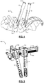
- FIG. 2 illustrates a perspective view of an exemplary instrument 100 for compression and distraction of the vertebrae V1 and V2 of the spinal column 10 according to the principles of the present disclosure.
- the instrument 100 includes a first receiver 102, a second receiver 104, and a positioner member 106.
- the first receiver 102 may attach to the first extender 20 and the second receiver 104 may attach to the second extender 30 of FIG. 1 .
- the extenders 20, 30 may include various features that limit rotational or translational movement when attached to the instrument 100.
- the tabs 24, 34 may engage with features of the receivers 102 and 104 described herein.
- the positioner member 106 positions at least one of the first and second receivers 102 and 104.
- the positioner member 106 translates the second receiver 104 relative to the first receiver 102.
- a guide member 108 guides the movement of at least one of the first and second receivers 102 and 104.
- the guide member 108 may extend parallel to the positioner member 106 and through the second receiver 104 to guide its movement relative to the first receiver 102.
- the first receiver 102 further includes a fixed portion 110 and a rotatable portion 112. The rotatable portion 112 rotates or pivot to various angles relative to the fixed portion 110.
- FIGS. 3-7 illustrate additional features of the instrument 100 that provide greater flexibility for attachment of the extenders 20 and 30 as well as positioning and angulation to provide appropriate compression and distraction forces on the vertebrae V1 and V2.
- the rotatable portion 112 includes a first extender aperture 114 for receiving the first extender 20.
- the second receiver 104 includes a second extender aperture 116 for receiving the second extender 30.
- the fixed portion 110 and second receiver 104 receive the positioner member 106 and the guide member 108.
- the positioner member 106 positions the second receiver 104 relative to the first receiver 102 in a first direction along a longitudinal axis of the positioner member 106.
- the guide member 108 guides the second receiver 104 and prevents rotation about the positioner member 106 as it rotates to position the second receiver 104.
- the positioner member 106 may include a first shaft 118 with a first end 120 that extends through the first receiver 102 and terminates in an adjuster 122 or knob.
- the first end 120 may rotate freely within the first receiver 102.
- the adjuster 122 may be used to rotate the positioner member 106.
- the adjuster 122 may be secured to the first end 120 with a lock pin.
- the shaft 118 may include a threaded portion 124 that engages with features within the second receiver 104.
- the threaded portion 124 may rotate in a first direction to position the second receiver 104 away from the first receiver 102 and a second opposite direction to position the second receiver 104 towards the first receiver 102.
- a second end 126 of the positioner member 106 may couple with an end coupler 128.
- the second end 126 may rotate freely within the end coupler 128.
- the guide member 108 extends through the first and second receivers 102 and 104 and guides the movement of the second receiver 104.
- the guide member 108 may include a second shaft 130 with a first end 132 received by the first receiver 102.
- the second shaft 130 may include a substantially smooth, cylindrical surface.
- the first end 132 may be secured within the first receiver 102 with a lock pin.
- the guide member 108 extends away from the first receiver 102 and through the second receiver 104 substantially parallel to the positioner member 106.
- a second end 134 of the second shaft 130 may couple with the end coupler 128.
- the second end 134 may be secured by the end coupler 128.
- the shaft 130 may include markings indicating distances between the first and second receivers 102 and 104.
- the instrument 100 may include attachment features for quick attachment to and removal from the extenders 20 and 30.
- radial tabs 136 may extend radially inward from sidewalls of the apertures 114 and 116.
- the radial tabs 136 may be configured to engage the proximally extending tabs 24 and 34 on the proximal ends of the first and second extenders 20 and 30.
- Each aperture may include a plurality of radial tabs 136.
- the radial tabs 136 may be aligned at approximately 90 degree intervals around the apertures 114 and 116.
- the tabs 136 may restrict rotation of the extenders 20 and 30 within the apertures 114 and 116.
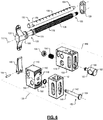
- FIGS. 6 and 7 are exploded views of the instrument 100 illustrating various examples of features that permit the rotational positioning of the first receiver 102.
- the first receiver 102 includes the rotatable portion 112 and the fixed portion 110.
- a lock member 138 couples the fixed portion 110 and the rotatable portion 112.
- the lock member 138 includes a lock arm 140 and a lock shaft 142.
- the lock shaft 142 extends through the fixed portion 110 and the rotatable portion 112 of the first receiver 102.
- a lock pin 144 may pivotally couple the lock arm 140 with the lock shaft 142.
- the lock arm 140 engages the fixed portion 110 as it pivots about the lock pin 144.
- the lock pin 144 may be located off-center at a base portion of the lock arm 140. For example, as the lock arm 140 rotates, the lock pin 144 may translate towards or away from the fixed portion 110, thus moving the attached lock shaft 142 within the fixed portion 110.
- a first end 146 of the lock shaft 142 extends through a first lock aperture 148 in the fixed portion 110 and a second lock aperture 150 in the rotatable portion 112.
- the first end 146 of the lock shaft 142 may include a diameter less than or equal to a diameter of the first and second lock apertures 148 and 150 to permit sliding engagement therein.
- a second end 152 of the lock shaft 142 extends within the second lock aperture 150 and terminate in a lock cap 154.
- the lock cap 154 may include a diameter greater than the diameter of the first and second lock apertures 144 and 146 to prevent the second end 142 of the lock shaft 142 from passing therethrough.
- the rotatable portion 112 may rotate about the lock shaft 142.
- the lock arm 140 is used to actuate the lock member 138 and position the rotatable portion 112 relative to the fixed portion 110.
- the lock member 138 positions the rotatable portion 112 between a locked configuration shown in FIGS. 11 and 12 and a rotatable configuration with the fixed portion 110 shown in FIGS. 13 and 14 .
- the fixed portion 110 may include a first surface 156 that mates with a second surface 158 of the rotatable portion 112.
- the first surface 156 includes a first set of projections 160 extending towards the rotatable portion 112.
- the second surface 158 includes a second set of projections 162 extending towards the fixed portion 110.
- the first and second sets of projections 160 and 162 may extend radially from the first and second lock apertures 148 and 150 respectively.
- a bias device 164 such as a spring may bias the rotatable portion 112 away from the fixed portion 110.
- the lock member 138 positions the fixed portion 110 and the rotatable portion 112 in the locked configuration.
- the lock arm 140 applies force to pull on the lock shaft 142 in a first direction 165.
- the lock shaft 142 pulls on the lock cap 154 within the second lock aperture 150.
- the lock cap 154 having a larger diameter than the second lock aperture 150, may not pass through the second lock aperture 150.
- the lock cap 154 thus transfers the force to the rotatable portion 112 to pull the rotatable portion 112 towards the fixed portion 110.
- the fixed portion 110 engages the rotatable portion 112.
- the first set of projections 160 engages the second set of projections 162 to prevent rotation of the rotatable portion 112 relative to the fixed portion 110.
- the lock member 138 positions the fixed portion 110 and the rotatable portion 112 in the rotatable configuration.
- the lock arm 140 rotates and reduces force on the lock shaft 142.
- the bias spring 164 may bias the rotatable portion 112 away from the fixed portion 110 in a second direction 167.
- the first set of projections 160 disengages the second set of projections 162 to allow rotation of the rotatable portion 112 relative to the fixed portion 110.
- the first receiver 102 may be positioned at various angles relative to the second receiver 104.
- the lock member 138 may position the rotatable portion 112 and fixed portion 110 in the rotatable configuration. A surgeon may then rotate the rotatable portion 112 about the lock shaft 142.
- a longitudinal axis 169 of the first extender aperture 114 may include an angle A relative to a longitudinal axis 171 of the second extender aperture 116. The angle A may be adjusted by rotating the rotatable portion 112 as shown by arrow 173 and translating the second receiver 104 as shown by arrow 175.
- the exploded views of the instrument 100 illustrate various examples of features that facilitate the translational positioning of the second receiver 104 relative to the first receiver 102.
- the first receiver 102 and second receiver 104 include various apertures and/or bores to receive the positioner member 106 and guide member 108.
- a first positioner aperture 166 extends through the fixed portion 110 of the first receiver 102.
- the first positioner aperture 166 may extend transverse to the first lock aperture 148.
- the first positioner aperture 166 may be disposed distal to the first lock aperture 148.
- the first positioner aperture 166 may receive the first end 120 of the positioner member 106.
- the first end 120 may include a smooth, cylindrical outer surface that rotates freely within the first positioner aperture 166.
- the first end 120 may extend outside the first positioner aperture 166 to couple with the adjuster 122 via a removable pin 168.
- a retaining member 170 on the shaft 118 may retain the first end 120 of the positioner member 106 within the opposite end of the first lock aperture 148 as illustrated in FIGS. 12 and 14 .
- a clip or guide wheel may rotate within a widened portion 172 of the first positioner aperture 166.
- a first guide aperture 174 extends into the fixed portion of the first receiver 102.
- the first guide aperture 174 may extend transverse to the first lock aperture 148 and parallel to the first positioner aperture 166.
- the first guide aperture 174 may be disposed proximal to the first lock aperture 148.
- the first guide aperture 174 may receive the first end 132 of the guide member 108.
- the first end 132 may include a smooth, cylindrical outer surface that rotates freely within the first guide aperture 174.
- an anti-rotation pin 176 may lock the guide member 108 to prevent rotation.
- the first end 132 may be locked within the fixed portion 110 of the first receiver by the pin 176.
- a second positioner aperture 178 extends through the second receiver 104.
- the second positioner aperture 178 may receive the threaded portion 124 of the positioner member 106.
- the second end 126 of the positioner member 106 may extend outside the second positioner aperture 178.
- the second end 126 may include a smooth, cylindrical outer surface that rotates freely within the end coupler 128.
- the second receiver 104 further includes a release member 180 for releasably engaging the positioner member 106, shown in detail in the cross-sectional view of FIG. 9 .
- the release member 180 may include a sleeve 182 and a release actuator 184.
- the sleeve 182 may include a thru-hole 186 that receives the threaded portion 124 of the positioner member 106.
- the thru-hole 186 may be formed from two separate, intersecting bores. A first bore may be tapped and a second bore may be smooth.
- the thru-hole 186 may include a threaded portion 188 and a non-threaded portion 190.
- the threaded portion 188 and the non-threaded portion 190 may be disposed on opposite sides of the thru-hole 186.
- the release member 180 may slide within a release aperture 192 inside the second receiver 104.
- the release aperture 192 may communicate with the second positioner aperture 178.
- the release aperture 192 may extend transverse to the second positioner aperture.
- a release spring 194 within the release aperture 192 may bias the release member 180.
- the release spring 194 may engage the release actuator 184 and a narrowed portion 196 or internal ridge of the release aperture 192.
- the thru-hole 186 may align with the second positioner aperture 178 to permit passage of the positioner member 106 there through.
- a second guide aperture 198 through the second receiver 104 may extend transverse to the release aperture 192 and parallel to the second positioner aperture 178.
- the second guide aperture 198 may be disposed proximal to the release aperture 192.
- the first guide aperture 174 may receive the second end 134 of the guide member 108.
- the second end 134 may include a smooth, cylindrical outer surface that rotates freely within the second guide aperture 198.
- the second end 134 may couple with the end coupler 128.
- FIGS. 16-19 illustrate actuation of the release member 180 between an engaged configuration and a released configuration.
- the release actuator 184 may position the sleeve 182 to engage the threaded portion 188 with the threaded portion 124 of the positioner member 106 in the engaged configuration.
- the release spring 194 may bias the sleeve 182 into engagement.
- rotating the positioner member 106 translates the second receiver 104 along the length of the threaded portion 124.
- the surgeon may also apply compression and distraction forces on attached screw extenders 20 and 30 as described in FIGS. 1 and 2 by rotating the positioner member 106.
- the threaded engagement maintains the position of the second receiver 104 as the surgeon performs incremental adjustments.
- the surgeon may prefer to position the second receiver 104 more quickly than by rotating the positioner member 106.
- the second receiver 104 may be too close or too far from the first receiver 102 to attach to the screw extenders 20 and 30.
- the release member 180 may be positioned into the released configuration to quickly move the second receiver 104 along the length of the threaded portion 124.
- the release actuator 184 may be depressed to position the sleeve 182 to disengage the threaded portion 188 from the threaded portion 124 of the positioner member 106 in the released configuration.
- the non-threaded portion 190 may engage the threaded portion 124 of the positioner member 106 as well.
- the release spring 194 may compress as the sleeve 182 advances into the release aperture 192. With the threaded portions 124 and 188 disengaged, rotating the positioner member 106 no longer translates the second receiver 104 along the length of the threaded portion 124. The surgeon may freely translate the second receiver 104 to quickly position the instrument 100 for attachment to the screw extenders 20 and 30.
- FIGS. 20-25 illustrate another exemplary instrument 200 for compression and distraction of the vertebrae V1 and V2 of the spinal column 10 according to the principles of the present disclosure.
- the instrument 200 shares some similar features as the instrument 100 of FIGS. 1-19 which are denoted with similar numerals throughout.
- the instrument 200 includes a first receiver 202 and a second receiver 204 for attachment of the extenders 20 and 30 as well as positioning to provide appropriate compression and distraction forces on the vertebrae V1 and V2.
- the instrument 200 may translate the second receiver 204 relative to the first receiver 202.
- the instrument 200 may include a positioner member 206 and a guide member 208.
- the first receiver 202 may include a first extension member aperture 214 for receiving the first extender 20.
- the second receiver 204 may include a second extension member aperture 216 for receiving the second extender 30.
- the positioner member 206 positions the second receiver 204 relative to the first receiver 202 in a first direction along a longitudinal axis of the positioner member 206.
- the guide member 208 guides the second receiver 204 and prevents rotation about the positioner member 206 as it rotates to position the second receiver 204.
- the positioner member 206 may include a first shaft 218 with a first end 220 that extends through the first receiver 202 and terminates in an adjuster 222 or knob.
- the first end 220 may rotate freely within the first receiver 202.
- the adjuster 222 may be used to rotate the positioner member 206.
- the adjuster 222 may be secured to the first end 220 with a lock pin.
- the shaft 218 may include a threaded portion 224 that engages with features within the second receiver 204.
- the threaded portion 224 may rotate in a first direction to position the second receiver 204 away from the first receiver 202 and a second opposite direction to position the second receiver 204 towards the first receiver 202.
- a second end 226 of the positioner member 206 may couple with an end coupler 228.
- the second end 226 may rotate freely within the end coupler 228.
- the guide member 208 extends through the first and second receivers 202 and 204 and guides the movement of the second receiver 104.
- the guide member 208 may include a second shaft 130 with a first end 132 received by the first receiver 102.
- the second shaft 230 may include a substantially smooth, cylindrical surface.
- the first end 232 may be secured within the first receiver 202 with a lock pin.
- the guide member 208 extends away from the first receiver 202 and through the second receiver 204 substantially parallel to the positioner member 206.
- a second end 234 of the second shaft 230 may couple with the end coupler 228.
- the second end 234 may be secured by the end coupler 228.
- the shaft 230 may include markings indicating distances between the first and second receivers 202 and 204.
- the instrument 200 may include attachment features for quick attachment to and removal from the extenders 20 and 30.
- radial tabs 236 may extend radially inward from sidewalls of the apertures 214 and 216.
- the radial tabs 236 may be configured to engage the proximally extending tabs 24 and 34 on the proximal ends of the first and second extenders 20 and 30.
- Each aperture may include a plurality of radial tabs 236.
- the radial tabs 236 may be aligned at approximately 90 degree intervals around the apertures 214 and 216.
- the tabs 236 may restrict rotation of the extenders 20 and 30 within the apertures 214 and 216.
- FIGS. 23-25 cross-sectional views of the instrument 200 illustrate features for receiving the positioner member 206 and guide member 208.
- the first receiver 202 includes a first positioner aperture 266 and first guide aperture 274.
- the second receiver 204 includes a second positioner aperture 286 and a second guide aperture 298.
- the second positioner aperture 286 may be threaded to engage with a threaded portion 224 of the positioner member 206.
- the instrument 100 includes the first receiver 102, the second receiver 104, and the positioner member 106 as described with reference to FIGS. 2-5 .
- the first receiver 102 may attach to the first extender 20 and the second receiver 104 may attach to the second extender 30 of FIG. 1 .
- the extenders 20, 30 may include various features that limit rotational or translational movement when attached to the instrument 100.
- the extenders 20, 30 may include threading that engages coupling screws 220, 230.
- the positioner member 106 may position at least one of the first and second receivers 102 and 104.
- the positioner member 106 may translate the second receiver 104 relative to the first receiver 102.
- the guide member 108 may guide the movement of at least one of the first and second receivers 102 and 104.
- the guide member 108 may extend parallel to the positioner member 106 and through the second receiver 104 to guide its movement relative to the first receiver 102.
- Like numbers are used throughout FIGS. 26-29 to reference the same or similar elements as FIGS. 1-7 .
- both the first receiver 102 and the second receiver 104 include rotatable portions 112a and 112b (collectively rotatable portions 112).
- the rotatable portions 112 rotate or pivot to various angles relative to the fixed (translatable) portion 110b of the second receiver 104 and the fixed (non-translatable) portion 110a of the first receiver 102 respectively. That is, both the first and second receivers 102 and 104 include fixed portions 110a and 110b (collectively fixed portions 110) that are rotatably fixed relative to the guide member 108.
- the rotatable portions 112 include the first extender aperture 114 for receiving the first extender 20 and the second extender aperture 116 for receiving the second extender 30.
- the fixed (translatable) portion 110b and the fixed (non-translatable) portion 110a may receive the positioner member 106 and the guide member 108.
- the positioner member 106 positions the second receiver 104 relative to the first receiver 102 in a first direction along a longitudinal axis of the positioner member 106.
- the guide member 108 guides the second receiver 104 and prevents rotation about the positioner member 106 as it rotates to position the second receiver 104.
- the positioner member 106 may include the first shaft 118 with the first end 120 that extends through the first receiver 102 and terminates in the adjuster 122 or knob.
- the first end 120 may rotate freely within the first receiver 102.
- the adjuster 122 may be used to rotate the positioner member 106.
- the adjuster 122 may be secured to the first end 120 with a lock pin.
- the shaft 118 may include a threaded portion 124 that engages with features within the second receiver 104.
- the threaded portion 124 may rotate in a first direction to position the second receiver 104 away from the first receiver 102 and a second opposite direction to position the second receiver 104 towards the first receiver 102.
- the second end 126 of the positioner member 106 may couple with the end coupler 128.
- the second end 126 may rotate freely within the end coupler 128.
- the guide member 108 extends through the first and second receivers 102 and 104 and guides the movement of the second receiver 104.
- the guide member 108 may include the second shaft 130 with the first end 132 received by the first receiver 102.
- the second shaft 130 may include a substantially smooth, cylindrical surface.
- the first end 132 may be secured within the first receiver 102 with a lock pin.
- the guide member 108 extends away from the first receiver 102 and through the second receiver 104 substantially parallel to the positioner member 106.
- the second end 134 of the second shaft 130 may couple with the end coupler 128.
- the second end 134 may be secured by the end coupler 128.
- the shaft 130 may include markings indicating distances between the first and second receivers 102 and 104.
- the instrument 100 may couple with the screw extenders 20 and 30 using coupling screws 220, 230.
- FIG. 29 is an exploded view of the instrument 100 illustrating various examples of features that permit the rotational positioning of the first receiver 102 and the second receiver 104.
- the first receiver 102 includes the first rotatable portion 112a and the fixed (non-translatable) portion 110a.
- Each receiver may include a lock member similar to lock member 138.
- a first lock member 138a may couple the fixed portion 110a and the rotatable portion 112a.
- the lock member 138a may include a lock arm 140a and a lock shaft 142a.
- the lock shaft 142a may extend through the fixed portion 110a and the rotatable portion 112a of the first receiver 102.
- a lock pin 144a may pivotally couple the lock arm 140a with the lock shaft 142a.
- the lock arm 140a may engage the fixed portion 110a as it pivots about the lock pin 144a.
- the lock pin 144a may be located off-center at a base portion of the lock arm 140a. For example, as the lock arm 140a rotates, the lock pin 144a may translate towards or away from the fixed portion 110a, thus moving the attached lock shaft 142a within the fixed portion 110a.
- the second receiver 104 may include the second rotatable portion 112b and the fixed (translatable) portion 110b.
- a second lock member 138b includes the same or similar features of the first lock member 138a.
- the exploded view of the instrument 100 in FIG. 29 illustrates various examples of features that facilitate the translational positioning of the second receiver 104 relative to the first receiver 102.
- the first receiver 102 and second receiver 104 include various apertures and/or bores to receive the positioner member 106 and guide member 108 similar to the instrument 100 as shown in FIGS. 1-7 .
- the second receiver 104 further includes a release member for releasably engaging the positioner member 106.
- the release member may be integral with the lock shaft 142b.
- the release member may include the sleeve 182 and the release actuator 184.
- the sleeve 182 may include the thru-hole 186 that receives the threaded portion 124 of the positioner member 106.
- the thru-hole 186 may be formed from two separate, intersecting bores. The first bore may be tapped and the second bore may be smooth.
- the thru-hole 186 may include the threaded portion (not shown) and the non-threaded portion 190.
- the threaded portion and the non-threaded portion 190 may be disposed on opposite sides of the thru-hole 186.
- the release member 180 may slide within the release aperture 192 inside the second receiver 104.
- the release aperture 192 may communicate with the second positioner aperture 178.
- the release aperture 192 may extend transverse to the second positioner aperture.
- a release spring 194b within the release aperture 192 may bias the release member 180.
- the release spring 194 may engage the release actuator 184 and a narrowed portion 196 or internal ridge of the release aperture 192.
- the thru-hole 186 may align with the second positioner aperture 178 to permit passage of the positioner member 106 there through.
- a second guide aperture 198 through the second receiver 104 may extend transverse to the release aperture 192 and parallel to the second positioner aperture 178.
- the second guide aperture 198 may be disposed proximal to the release aperture 192.
- the first guide aperture 174 may receive the second end 134 of the guide member 108.
- the second end 134 may include a smooth, cylindrical outer surface that rotates freely within the second guide aperture 198.
- the second end 134 may couple with the end coupler 128.
Landscapes
- Health & Medical Sciences (AREA)
- Orthopedic Medicine & Surgery (AREA)
- Neurology (AREA)
- Life Sciences & Earth Sciences (AREA)
- Surgery (AREA)
- Heart & Thoracic Surgery (AREA)
- Engineering & Computer Science (AREA)
- Biomedical Technology (AREA)
- Nuclear Medicine, Radiotherapy & Molecular Imaging (AREA)
- Medical Informatics (AREA)
- Molecular Biology (AREA)
- Animal Behavior & Ethology (AREA)
- General Health & Medical Sciences (AREA)
- Public Health (AREA)
- Veterinary Medicine (AREA)
- Surgical Instruments (AREA)
Description
- The present invention relates to surgical devices for spinal surgery, and in particular to instruments for applying compression and/or distraction forces to the spine. Associated methods are also described herein to aid understanding the invention. These methods do not form part of the claimed invention.
- The spine is a flexible column formed of a plurality of bones called vertebrae. The vertebrae are hollow and piled one upon the other, forming a strong hollow column for support of the cranium and trunk. The hollow core of the spine houses and protects the nerves of the spinal cord. The different vertebrae are connected to one another by means of articular processes and intervertebral, fibrocartilaginous bodies. Various spinal disorders may cause the spine to become misaligned, curved, and/or twisted or result in fractured and/or compressed vertebrae. It is often necessary to surgically correct these spinal disorders.
- The spine includes seven cervical (neck) vertebrae, twelve thoracic (chest) vertebrae, five lumbar (lower back) vertebrae, and the fused vertebrae in the sacrum and coccyx that help to form the hip region. While the shapes of individual vertebrae differ among these regions, each is essentially a short hollow shaft containing the bundle of nerves known as the spinal cord. Individual nerves, such as those carrying messages to the arms or legs, enter and exit the spinal cord through gaps between vertebrae.
- The spinal disks act as shock absorbers, cushioning the spine, and preventing individual bones from contacting each other. Disks also help to hold the vertebrae together. The weight of the upper body is transferred through the spine to the hips and the legs. The spine is held upright through the work of the back muscles, which are attached to the vertebrae. While the normal spine has no side-to-side curve, it does have a series of front-to-back curves, giving it a gentle "S" shape. If the proper shaping and/or curvature are not present due to scoliosis, neuromuscular disease, cerebral palsy, or other disorder, it may be necessary to straighten or adjust the spine into a proper curvature.
- Generally the correct curvature is obtained by manipulating the vertebrae into their proper position and securing that position with a rigid system of screws and rods. The screws may be inserted into the pedicles of the vertebrae to act as bone anchors, and the rods may be inserted into heads of the screws. Two rods may run substantially parallel to the spine and secure the spine in the desired shape and curvature. Thus the rods, which are shaped to mimic the correct spinal curvature, force the spine into proper alignment. Bone grafts are then placed between the vertebrae and aid in fusion of the individual vertebrae together to form a correctly aligned spine.
- In many surgical spinal procedures, such as, for example, the correction of scoliosis, nerve root decompression, interbody fusion, repair of kyphosis and treatment of other spinal defects or trauma, it is desirable or necessary to supply forces by compression and/or distraction in the defective region. While there are devices that exist for applying forces to the spine, there remains a need for devices and methods that improve surgeon efficiency and provide the surgeon additional options in the application of such forces. The present invention is directed toward meeting these needs, among others.
-
US 2008/0077155 A1 discloses a displacement device having at least a first arm, a second arm, and a connector. Various embodiments of the connector include a lateral adjustment mechanism for adjusting the distance between the first arm and the second arm and an angular adjustment mechanism for adjusting the angle between the first arm and the second arm. - According to the present invention, there is provided an instrument for compression and distraction of vertebrae as set out in
claim 1 below. - Optional features of the invention are set out in the dependent claims below.
- In other features, the positioner member includes a shaft with a threaded portion and the guide member is substantially parallel to the positioner member. The fixed portion includes a first surface with a first plurality of projections that mates with a second plurality of projections on a second surface of the rotatable portion.
- In still other features, the second receiver freely slides along the positioner member and guide member when the release member is in a released configuration and threadably moves along the positional member in an engaged configuration. A release member disengages the second receiver from the positioner member in the released configuration and engages the second receiver with the positioner member in the engaged configuration. The release member includes a partially threaded sleeve slidably extending through a release aperture of the second receiver and coupled with a release button and bias spring that biases the release member into the engaged configuration.
-
-
FIG. 1 is a perspective view of a portion of a spinal column including attached screw extenders. -
FIG. 2 is a perspective view of an exemplary instrument for compression and distraction of the spinal column using the screw extenders ofFIG. 1 according to the principles of the present disclosure. -
FIG. 3 is a perspective view of the instrument according to the principles of the present disclosure. -
FIG. 4 is a front view of the instrument according to the principles of the present disclosure. -
FIG. 5 is a top view of the instrument according to the principles of the present disclosure. -
FIG. 6 is an exploded perspective view of the instrument according to the principles of the present disclosure. -
FIG. 7 is an exploded perspective view of the instrument according to the principles of the present disclosure. -
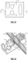
FIG. 8 is a cross-sectional view of the instrument ofFIG. 4 looking into a plane VIII according to the principles of the present disclosure. -
FIG. 9 is a cross-sectional view of the instrument ofFIG. 4 looking into a plane IX according to the principles of the present disclosure. -
FIG. 10 is a cross-sectional view of the instrument ofFIG. 5 looking into a plane X according to the principles of the present disclosure. -
FIG. 11 is a side view of the instrument according to the principles of the present disclosure. -
FIG. 12 is a partial cross-sectional view of the instrument ofFIG. 11 looking into a plane XII according to the principles of the present disclosure. -
FIG. 13 is a side view of the instrument according to the principles of the present disclosure. -
FIG. 14 is a partial cross-sectional view of the instrument ofFIG. 13 looking into a plane XIV according to the principles of the present disclosure. -
FIG. 15 is a partial front view of the instrument according to the principles of the present disclosure. -
FIG. 16 is a side view of a portion of the instrument according to the principles of the present disclosure. -
FIG. 17 is a partial cross-sectional view of the portion of the instrument ofFIG. 16 engaging another portion of the instrument, looking into a plane XVII according to the principles of the present disclosure. -
FIG. 18 is a side view of a portion of the instrument according to the principles of the present disclosure. -
FIG. 19 is a partial cross-sectional view of the portion of the instrument ofFIG. 18 engaging another portion of the instrument, looking into a plane XIX according to the principles of the present disclosure. -
FIG. 20 is a perspective view of another exemplary instrument according to the principles of the present disclosure. -
FIG. 21 is a front view of the instrument ofFIG. 20 according to the principles of the present disclosure. -
FIG. 22 is a top view of the instrument ofFIG. 20 according to the principles of the present disclosure. -
FIG. 23 is a cross-sectional view of the instrument ofFIG. 21 looking into a plane XXIII according to the principles of the present disclosure. -
FIG. 24 is a cross-sectional view of the instrument ofFIG.21 looking into a plane XXIV according to the principles of the present disclosure. -
FIG. 25 is a cross-sectional view of the instrument ofFIG. 22 looking into a plane XXV according to the principles of the present disclosure. -
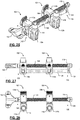
FIGS. 26-29 illustrate the instrument including a non-translatable receiver with a first rotatable portion and a translatable receiver with a second rotatable portion according to the principles of the present disclosure. - Embodiments of the invention will now be described with reference to the Figures, wherein like numerals reflect like elements throughout. The terminology used in the description presented herein is not intended to be interpreted in any limited or restrictive way, simply because it is being utilized in conjunction with detailed description of certain specific embodiments of the invention. Furthermore, embodiments of the invention may include several novel features, no single one of which is solely responsible for its desirable attributes or which is essential to practicing the invention described herein. The words proximal and distal are applied herein to denote specific ends of components of the instrument described herein. A proximal end refers to the end of an instrument nearer to an operator of the instrument when the instrument is being used. A distal end refers to the end of a component further from the operator and extending towards the surgical area of a patient and/or the implant.
-
FIG. 1 illustrates a perspective view of a portion of aspinal column 10 including a first vertebra V1 and a second vertebra V2. Although the portion shown includes the lumbar and sacral regions of thespinal column 10, the invention of the present disclosure may be used in other regions including the cervical and thoracic regions of the spine. Screws may be inserted into the first and second vertebrae V1 and V2 through minimally invasive surgery. For example, the screws may be inserted into the pedicles of the vertebrae. Subsequently, additional instrumentation may be inserted to manipulate the vertebrae into proper alignment, to reduce deformity, and to compress or distract the vertebrae. - Continuing with
FIG. 1 , afirst screw extender 20 may be attached to a first screw (not shown) inserted into the first vertebra V1. Asecond screw extender 30 may be attached to a second screw (not shown) inserted into the second vertebra V2. At distal ends, theextenders flexible tabs extenders tabs - For ease of discussion, the
screw extenders U.S. Pub. No. 2009/0171391 andU.S. Pub. No. 2010/0036443 . -
FIG. 2 illustrates a perspective view of anexemplary instrument 100 for compression and distraction of the vertebrae V1 and V2 of thespinal column 10 according to the principles of the present disclosure. Theinstrument 100 includes afirst receiver 102, asecond receiver 104, and apositioner member 106. Thefirst receiver 102 may attach to thefirst extender 20 and thesecond receiver 104 may attach to thesecond extender 30 ofFIG. 1 . Theextenders instrument 100. For example, as shown inFIG. 1 , thetabs receivers positioner member 106 positions at least one of the first andsecond receivers positioner member 106 translates thesecond receiver 104 relative to thefirst receiver 102. Aguide member 108 guides the movement of at least one of the first andsecond receivers guide member 108 may extend parallel to thepositioner member 106 and through thesecond receiver 104 to guide its movement relative to thefirst receiver 102. Thefirst receiver 102 further includes a fixedportion 110 and arotatable portion 112. Therotatable portion 112 rotates or pivot to various angles relative to the fixedportion 110. -
FIGS. 3-7 illustrate additional features of theinstrument 100 that provide greater flexibility for attachment of theextenders rotatable portion 112 includes afirst extender aperture 114 for receiving thefirst extender 20. Thesecond receiver 104 includes asecond extender aperture 116 for receiving thesecond extender 30. The fixedportion 110 andsecond receiver 104 receive thepositioner member 106 and theguide member 108. Thepositioner member 106 positions thesecond receiver 104 relative to thefirst receiver 102 in a first direction along a longitudinal axis of thepositioner member 106. Theguide member 108 guides thesecond receiver 104 and prevents rotation about thepositioner member 106 as it rotates to position thesecond receiver 104. - The
positioner member 106 may include afirst shaft 118 with afirst end 120 that extends through thefirst receiver 102 and terminates in anadjuster 122 or knob. Thefirst end 120 may rotate freely within thefirst receiver 102. Theadjuster 122 may be used to rotate thepositioner member 106. Theadjuster 122 may be secured to thefirst end 120 with a lock pin. Theshaft 118 may include a threadedportion 124 that engages with features within thesecond receiver 104. The threadedportion 124 may rotate in a first direction to position thesecond receiver 104 away from thefirst receiver 102 and a second opposite direction to position thesecond receiver 104 towards thefirst receiver 102. Asecond end 126 of thepositioner member 106 may couple with anend coupler 128. Thesecond end 126 may rotate freely within theend coupler 128. - The
guide member 108 extends through the first andsecond receivers second receiver 104. Theguide member 108 may include asecond shaft 130 with afirst end 132 received by thefirst receiver 102. Thesecond shaft 130 may include a substantially smooth, cylindrical surface. Thefirst end 132 may be secured within thefirst receiver 102 with a lock pin. Theguide member 108 extends away from thefirst receiver 102 and through thesecond receiver 104 substantially parallel to thepositioner member 106. Asecond end 134 of thesecond shaft 130 may couple with theend coupler 128. Thesecond end 134 may be secured by theend coupler 128. Theshaft 130 may include markings indicating distances between the first andsecond receivers - The
instrument 100 may include attachment features for quick attachment to and removal from theextenders FIG. 5 ,radial tabs 136 may extend radially inward from sidewalls of theapertures radial tabs 136 may be configured to engage theproximally extending tabs second extenders radial tabs 136. For example, theradial tabs 136 may be aligned at approximately 90 degree intervals around theapertures tabs 136 may restrict rotation of theextenders apertures -
FIGS. 6 and7 are exploded views of theinstrument 100 illustrating various examples of features that permit the rotational positioning of thefirst receiver 102. For example, thefirst receiver 102 includes therotatable portion 112 and the fixedportion 110. Alock member 138 couples the fixedportion 110 and therotatable portion 112. Thelock member 138 includes alock arm 140 and alock shaft 142. Thelock shaft 142 extends through the fixedportion 110 and therotatable portion 112 of thefirst receiver 102. Alock pin 144 may pivotally couple thelock arm 140 with thelock shaft 142. Thelock arm 140 engages the fixedportion 110 as it pivots about thelock pin 144. Thelock pin 144 may be located off-center at a base portion of thelock arm 140. For example, as thelock arm 140 rotates, thelock pin 144 may translate towards or away from the fixedportion 110, thus moving the attachedlock shaft 142 within the fixedportion 110. - Referring also to
FIG. 8 , afirst end 146 of thelock shaft 142 extends through afirst lock aperture 148 in the fixedportion 110 and asecond lock aperture 150 in therotatable portion 112. Thefirst end 146 of thelock shaft 142 may include a diameter less than or equal to a diameter of the first andsecond lock apertures second end 152 of thelock shaft 142 extends within thesecond lock aperture 150 and terminate in alock cap 154. Thelock cap 154 may include a diameter greater than the diameter of the first andsecond lock apertures second end 142 of thelock shaft 142 from passing therethrough. Therotatable portion 112 may rotate about thelock shaft 142. - The
lock arm 140 is used to actuate thelock member 138 and position therotatable portion 112 relative to the fixedportion 110. Thelock member 138 positions therotatable portion 112 between a locked configuration shown inFIGS. 11 and 12 and a rotatable configuration with the fixedportion 110 shown inFIGS. 13 and 14 . The fixedportion 110 may include afirst surface 156 that mates with asecond surface 158 of therotatable portion 112. InFIG. 6 , thefirst surface 156 includes a first set ofprojections 160 extending towards therotatable portion 112. InFIG. 7 , thesecond surface 158 includes a second set ofprojections 162 extending towards the fixedportion 110. The first and second sets ofprojections second lock apertures bias device 164, such as a spring may bias therotatable portion 112 away from the fixedportion 110. - In
FIGS. 11 and 12 , thelock member 138 positions the fixedportion 110 and therotatable portion 112 in the locked configuration. Thelock arm 140 applies force to pull on thelock shaft 142 in afirst direction 165. Thelock shaft 142 pulls on thelock cap 154 within thesecond lock aperture 150. Thelock cap 154, having a larger diameter than thesecond lock aperture 150, may not pass through thesecond lock aperture 150. Thelock cap 154 thus transfers the force to therotatable portion 112 to pull therotatable portion 112 towards the fixedportion 110. Thus, the fixedportion 110 engages therotatable portion 112. The first set ofprojections 160 engages the second set ofprojections 162 to prevent rotation of therotatable portion 112 relative to the fixedportion 110. InFIGS. 13 and 14 , thelock member 138 positions the fixedportion 110 and therotatable portion 112 in the rotatable configuration. Thelock arm 140 rotates and reduces force on thelock shaft 142. Thebias spring 164 may bias therotatable portion 112 away from the fixedportion 110 in asecond direction 167. The first set ofprojections 160 disengages the second set ofprojections 162 to allow rotation of therotatable portion 112 relative to the fixedportion 110. - Referring now to
FIG. 15 , thefirst receiver 102 may be positioned at various angles relative to thesecond receiver 104. For example, thelock member 138 may position therotatable portion 112 and fixedportion 110 in the rotatable configuration. A surgeon may then rotate therotatable portion 112 about thelock shaft 142. InFIG. 15 , alongitudinal axis 169 of thefirst extender aperture 114 may include an angle A relative to alongitudinal axis 171 of thesecond extender aperture 116. The angle A may be adjusted by rotating therotatable portion 112 as shown byarrow 173 and translating thesecond receiver 104 as shown by arrow 175. - Continuing with
FIGS. 6 and7 , the exploded views of theinstrument 100 illustrate various examples of features that facilitate the translational positioning of thesecond receiver 104 relative to thefirst receiver 102. For example, thefirst receiver 102 andsecond receiver 104 include various apertures and/or bores to receive thepositioner member 106 and guidemember 108. - Referring now also to the cross-sectional views of
FIGS. 8 and 10 , afirst positioner aperture 166 extends through the fixedportion 110 of thefirst receiver 102. Thefirst positioner aperture 166 may extend transverse to thefirst lock aperture 148. Thefirst positioner aperture 166 may be disposed distal to thefirst lock aperture 148. Thefirst positioner aperture 166 may receive thefirst end 120 of thepositioner member 106. Thefirst end 120 may include a smooth, cylindrical outer surface that rotates freely within thefirst positioner aperture 166. Thefirst end 120 may extend outside thefirst positioner aperture 166 to couple with theadjuster 122 via aremovable pin 168. A retainingmember 170 on theshaft 118 may retain thefirst end 120 of thepositioner member 106 within the opposite end of thefirst lock aperture 148 as illustrated inFIGS. 12 and14 . For example, a clip or guide wheel may rotate within a widenedportion 172 of thefirst positioner aperture 166. - A
first guide aperture 174 extends into the fixed portion of thefirst receiver 102. Thefirst guide aperture 174 may extend transverse to thefirst lock aperture 148 and parallel to thefirst positioner aperture 166. Thefirst guide aperture 174 may be disposed proximal to thefirst lock aperture 148. Thefirst guide aperture 174 may receive thefirst end 132 of theguide member 108. Thefirst end 132 may include a smooth, cylindrical outer surface that rotates freely within thefirst guide aperture 174. In other examples, ananti-rotation pin 176 may lock theguide member 108 to prevent rotation. Thefirst end 132 may be locked within the fixedportion 110 of the first receiver by thepin 176. - Similarly, a
second positioner aperture 178 extends through thesecond receiver 104. Thesecond positioner aperture 178 may receive the threadedportion 124 of thepositioner member 106. Thesecond end 126 of thepositioner member 106 may extend outside thesecond positioner aperture 178. Thesecond end 126 may include a smooth, cylindrical outer surface that rotates freely within theend coupler 128. Thesecond receiver 104 further includes arelease member 180 for releasably engaging thepositioner member 106, shown in detail in the cross-sectional view ofFIG. 9 . - The
release member 180 may include asleeve 182 and arelease actuator 184. Thesleeve 182 may include a thru-hole 186 that receives the threadedportion 124 of thepositioner member 106. The thru-hole 186 may be formed from two separate, intersecting bores. A first bore may be tapped and a second bore may be smooth. For example, the thru-hole 186 may include a threadedportion 188 and anon-threaded portion 190. The threadedportion 188 and thenon-threaded portion 190 may be disposed on opposite sides of the thru-hole 186. Therelease member 180 may slide within arelease aperture 192 inside thesecond receiver 104. Therelease aperture 192 may communicate with thesecond positioner aperture 178. Therelease aperture 192 may extend transverse to the second positioner aperture. Arelease spring 194 within therelease aperture 192 may bias therelease member 180. Therelease spring 194 may engage therelease actuator 184 and a narrowedportion 196 or internal ridge of therelease aperture 192. The thru-hole 186 may align with thesecond positioner aperture 178 to permit passage of thepositioner member 106 there through. - A
second guide aperture 198 through thesecond receiver 104. Thesecond guide aperture 198 may extend transverse to therelease aperture 192 and parallel to thesecond positioner aperture 178. Thesecond guide aperture 198 may be disposed proximal to therelease aperture 192. Thefirst guide aperture 174 may receive thesecond end 134 of theguide member 108. Thesecond end 134 may include a smooth, cylindrical outer surface that rotates freely within thesecond guide aperture 198. Thesecond end 134 may couple with theend coupler 128. -
FIGS. 16-19 illustrate actuation of therelease member 180 between an engaged configuration and a released configuration. InFIGS. 16 and 17 , therelease actuator 184 may position thesleeve 182 to engage the threadedportion 188 with the threadedportion 124 of thepositioner member 106 in the engaged configuration. Therelease spring 194 may bias thesleeve 182 into engagement. With the threadedportions positioner member 106 translates thesecond receiver 104 along the length of the threadedportion 124. The surgeon may also apply compression and distraction forces on attachedscrew extenders FIGS. 1 and 2 by rotating thepositioner member 106. The threaded engagement maintains the position of thesecond receiver 104 as the surgeon performs incremental adjustments. - In some situations, the surgeon may prefer to position the
second receiver 104 more quickly than by rotating thepositioner member 106. For example, prior to attaching theinstrument 100 to thescrew extenders second receiver 104 may be too close or too far from thefirst receiver 102 to attach to thescrew extenders release member 180 may be positioned into the released configuration to quickly move thesecond receiver 104 along the length of the threadedportion 124. InFIGS. 18 and 19 , therelease actuator 184 may be depressed to position thesleeve 182 to disengage the threadedportion 188 from the threadedportion 124 of thepositioner member 106 in the released configuration. Thenon-threaded portion 190 may engage the threadedportion 124 of thepositioner member 106 as well. Therelease spring 194 may compress as thesleeve 182 advances into therelease aperture 192. With the threadedportions positioner member 106 no longer translates thesecond receiver 104 along the length of the threadedportion 124. The surgeon may freely translate thesecond receiver 104 to quickly position theinstrument 100 for attachment to thescrew extenders -
FIGS. 20-25 illustrate another exemplary instrument 200 for compression and distraction of the vertebrae V1 and V2 of thespinal column 10 according to the principles of the present disclosure. The instrument 200 shares some similar features as theinstrument 100 ofFIGS. 1-19 which are denoted with similar numerals throughout. For example, the instrument 200 includes afirst receiver 202 and asecond receiver 204 for attachment of theextenders second receiver 204 relative to thefirst receiver 202. For example, the instrument 200 may include apositioner member 206 and aguide member 208. Thefirst receiver 202 may include a firstextension member aperture 214 for receiving thefirst extender 20. Thesecond receiver 204 may include a secondextension member aperture 216 for receiving thesecond extender 30. Thepositioner member 206 positions thesecond receiver 204 relative to thefirst receiver 202 in a first direction along a longitudinal axis of thepositioner member 206. Theguide member 208 guides thesecond receiver 204 and prevents rotation about thepositioner member 206 as it rotates to position thesecond receiver 204. - The
positioner member 206 may include afirst shaft 218 with afirst end 220 that extends through thefirst receiver 202 and terminates in anadjuster 222 or knob. Thefirst end 220 may rotate freely within thefirst receiver 202. Theadjuster 222 may be used to rotate thepositioner member 206. Theadjuster 222 may be secured to thefirst end 220 with a lock pin. Theshaft 218 may include a threadedportion 224 that engages with features within thesecond receiver 204. The threadedportion 224 may rotate in a first direction to position thesecond receiver 204 away from thefirst receiver 202 and a second opposite direction to position thesecond receiver 204 towards thefirst receiver 202. Asecond end 226 of thepositioner member 206 may couple with an end coupler 228. Thesecond end 226 may rotate freely within the end coupler 228. - The
guide member 208 extends through the first andsecond receivers second receiver 104. Theguide member 208 may include asecond shaft 130 with afirst end 132 received by thefirst receiver 102. Thesecond shaft 230 may include a substantially smooth, cylindrical surface. The first end 232 may be secured within thefirst receiver 202 with a lock pin. Theguide member 208 extends away from thefirst receiver 202 and through thesecond receiver 204 substantially parallel to thepositioner member 206. Asecond end 234 of thesecond shaft 230 may couple with the end coupler 228. Thesecond end 234 may be secured by the end coupler 228. Theshaft 230 may include markings indicating distances between the first andsecond receivers - The instrument 200 may include attachment features for quick attachment to and removal from the
extenders FIG. 22 ,radial tabs 236 may extend radially inward from sidewalls of theapertures radial tabs 236 may be configured to engage theproximally extending tabs second extenders radial tabs 236. For example, theradial tabs 236 may be aligned at approximately 90 degree intervals around theapertures tabs 236 may restrict rotation of theextenders apertures - Referring now to
FIGS. 23-25 , cross-sectional views of the instrument 200 illustrate features for receiving thepositioner member 206 and guidemember 208. Thefirst receiver 202 includes afirst positioner aperture 266 andfirst guide aperture 274. Thesecond receiver 204 includes asecond positioner aperture 286 and asecond guide aperture 298. Thesecond positioner aperture 286 may be threaded to engage with a threadedportion 224 of thepositioner member 206. - Referring now to
FIGS. 26-29 , theinstrument 100 includes thefirst receiver 102, thesecond receiver 104, and thepositioner member 106 as described with reference toFIGS. 2-5 . Thefirst receiver 102 may attach to thefirst extender 20 and thesecond receiver 104 may attach to thesecond extender 30 ofFIG. 1 . Theextenders instrument 100. For example, theextenders positioner member 106 may position at least one of the first andsecond receivers positioner member 106 may translate thesecond receiver 104 relative to thefirst receiver 102. Theguide member 108 may guide the movement of at least one of the first andsecond receivers guide member 108 may extend parallel to thepositioner member 106 and through thesecond receiver 104 to guide its movement relative to thefirst receiver 102. Like numbers are used throughoutFIGS. 26-29 to reference the same or similar elements asFIGS. 1-7 . - In the present example of the
instrument 100, both thefirst receiver 102 and thesecond receiver 104 includerotatable portions rotatable portions 112 rotate or pivot to various angles relative to the fixed (translatable)portion 110b of thesecond receiver 104 and the fixed (non-translatable)portion 110a of thefirst receiver 102 respectively. That is, both the first andsecond receivers portions guide member 108. Therotatable portions 112 include thefirst extender aperture 114 for receiving thefirst extender 20 and thesecond extender aperture 116 for receiving thesecond extender 30. The fixed (translatable)portion 110b and the fixed (non-translatable)portion 110a may receive thepositioner member 106 and theguide member 108. Thepositioner member 106 positions thesecond receiver 104 relative to thefirst receiver 102 in a first direction along a longitudinal axis of thepositioner member 106. Theguide member 108 guides thesecond receiver 104 and prevents rotation about thepositioner member 106 as it rotates to position thesecond receiver 104. - The
positioner member 106 may include thefirst shaft 118 with thefirst end 120 that extends through thefirst receiver 102 and terminates in theadjuster 122 or knob. Thefirst end 120 may rotate freely within thefirst receiver 102. Theadjuster 122 may be used to rotate thepositioner member 106. Theadjuster 122 may be secured to thefirst end 120 with a lock pin. Theshaft 118 may include a threadedportion 124 that engages with features within thesecond receiver 104. The threadedportion 124 may rotate in a first direction to position thesecond receiver 104 away from thefirst receiver 102 and a second opposite direction to position thesecond receiver 104 towards thefirst receiver 102. Thesecond end 126 of thepositioner member 106 may couple with theend coupler 128. Thesecond end 126 may rotate freely within theend coupler 128. - The
guide member 108 extends through the first andsecond receivers second receiver 104. Theguide member 108 may include thesecond shaft 130 with thefirst end 132 received by thefirst receiver 102. Thesecond shaft 130 may include a substantially smooth, cylindrical surface. Thefirst end 132 may be secured within thefirst receiver 102 with a lock pin. Theguide member 108 extends away from thefirst receiver 102 and through thesecond receiver 104 substantially parallel to thepositioner member 106. Thesecond end 134 of thesecond shaft 130 may couple with theend coupler 128. Thesecond end 134 may be secured by theend coupler 128. Theshaft 130 may include markings indicating distances between the first andsecond receivers instrument 100 may couple with thescrew extenders coupling screws -
FIG. 29 is an exploded view of theinstrument 100 illustrating various examples of features that permit the rotational positioning of thefirst receiver 102 and thesecond receiver 104. For example, thefirst receiver 102 includes the firstrotatable portion 112a and the fixed (non-translatable)portion 110a. Each receiver may include a lock member similar to lockmember 138. For example, afirst lock member 138a may couple the fixedportion 110a and therotatable portion 112a. Thelock member 138a may include alock arm 140a and alock shaft 142a. Thelock shaft 142a may extend through the fixedportion 110a and therotatable portion 112a of thefirst receiver 102. Alock pin 144a may pivotally couple thelock arm 140a with thelock shaft 142a. Thelock arm 140a may engage the fixedportion 110a as it pivots about thelock pin 144a. Thelock pin 144a may be located off-center at a base portion of thelock arm 140a. For example, as thelock arm 140a rotates, thelock pin 144a may translate towards or away from the fixedportion 110a, thus moving the attachedlock shaft 142a within the fixedportion 110a. Similarly, thesecond receiver 104 may include the secondrotatable portion 112b and the fixed (translatable)portion 110b. Asecond lock member 138b includes the same or similar features of thefirst lock member 138a. - Similar to the
instrument 100 as shown inFIGS. 6 and7 , the exploded view of theinstrument 100 inFIG. 29 illustrates various examples of features that facilitate the translational positioning of thesecond receiver 104 relative to thefirst receiver 102. For example, thefirst receiver 102 andsecond receiver 104 include various apertures and/or bores to receive thepositioner member 106 and guidemember 108 similar to theinstrument 100 as shown inFIGS. 1-7 . - The
second receiver 104 further includes a release member for releasably engaging thepositioner member 106. The release member may be integral with thelock shaft 142b. The release member may include thesleeve 182 and therelease actuator 184. Thesleeve 182 may include the thru-hole 186 that receives the threadedportion 124 of thepositioner member 106. The thru-hole 186 may be formed from two separate, intersecting bores. The first bore may be tapped and the second bore may be smooth. For example, the thru-hole 186 may include the threaded portion (not shown) and thenon-threaded portion 190. The threaded portion and thenon-threaded portion 190 may be disposed on opposite sides of the thru-hole 186. Therelease member 180 may slide within therelease aperture 192 inside thesecond receiver 104. Therelease aperture 192 may communicate with thesecond positioner aperture 178. Therelease aperture 192 may extend transverse to the second positioner aperture. Arelease spring 194b within therelease aperture 192 may bias therelease member 180. Therelease spring 194 may engage therelease actuator 184 and a narrowedportion 196 or internal ridge of therelease aperture 192. The thru-hole 186 may align with thesecond positioner aperture 178 to permit passage of thepositioner member 106 there through. - A
second guide aperture 198 through thesecond receiver 104. Thesecond guide aperture 198 may extend transverse to therelease aperture 192 and parallel to thesecond positioner aperture 178. Thesecond guide aperture 198 may be disposed proximal to therelease aperture 192. Thefirst guide aperture 174 may receive thesecond end 134 of theguide member 108. Thesecond end 134 may include a smooth, cylindrical outer surface that rotates freely within thesecond guide aperture 198. Thesecond end 134 may couple with theend coupler 128. - Example embodiments of the instruments of the present invention have been described herein. As noted elsewhere, these example embodiments have been described for illustrative purposes only, and are not limiting. Thus, the scope of the present invention should not be limited by any of the above-described exemplary embodiments, but should be defined only in accordance with the following claims.
Claims (6)
- An instrument for compression and distraction of vertebrae using screw extenders (20, 30), comprising:a first receiver (102) includinga fixed portion (110) with a first positioner aperture (166) and a first guide aperture (174); and a rotatable portion (112) with a first extender aperture (114) for attachment to a first screw extender (20), wherein the rotatable portion (112) is rotatable relative to the fixed portion (110) in a rotatable configuration and is rotatably fixed relative to the fixed portion (110) in a fixed configuration;a second receiver (104) including a second positioner aperture (178), a second guide aperture (198), and a second extender aperture (116) for attachment to a second extender (30);a positioner member (106) that translates one of the first and second receivers (102, 104) relative to the other of the first and second receivers (102, 104);a guide member (108) that guides the translation of the one of the first and second receivers (102, 104) relative to the other of the first and second receivers (102, 104); anda lock member (138) that disengages the rotatable portion (112) from the fixed portion (110) in the rotatable configuration and engages the rotatable portion (112) with the fixed portion (110) in the fixed configuration, wherein the lock member (138) includes a lock shaft (142) extending through a first lock aperture (148) of the fixed portion (110) and pivotally couples with a lock arm (140) at a first end and a lock cap (154) at a second end (152) within a second lock aperture (150) of the rotatable portion (112).
- The instrument of claim 1, wherein the positioner member (106) includes a shaft (118) with a threaded portion (124) and the guide member (108) is substantially parallel to the positioner member (106).
- The instrument of claim 1, wherein the fixed portion (110) includes a first surface (156) with a first plurality of projections (160) that mates with a second plurality of projections (162) on a second surface (158) of the rotatable portion (112).
- The instrument of claim 1, wherein the second receiver (104) freely slides along the positioner member (106) and guide member (108) in a released configuration and threadably moves along the positioner member (106) in an engaged configuration.
- The instrument of claim 4, further comprising a release member (180) that disengages the second receiver (104) from the positioner member (106) in the released configuration and engages the second receiver (104) with the positioner member (106) in the engaged configuration.
- The instrument of claim 5, wherein the release member (180) includes a partially threaded sleeve (182) slidably extending through a release aperture (192) of the second receiver (104) and coupled with a release button (184) and bias spring (194) that biases the release member (180) into the engaged configuration.
Applications Claiming Priority (2)
| Application Number | Priority Date | Filing Date | Title |
|---|---|---|---|
| US201261625264P | 2012-04-17 | 2012-04-17 | |
| PCT/US2013/036806 WO2013158660A1 (en) | 2012-04-17 | 2013-04-16 | Instrument and method for spinal compression and distraction |
Publications (3)
| Publication Number | Publication Date |
|---|---|
| EP2838455A1 EP2838455A1 (en) | 2015-02-25 |
| EP2838455A4 EP2838455A4 (en) | 2016-01-06 |
| EP2838455B1 true EP2838455B1 (en) | 2020-01-08 |
Family
ID=49384008
Family Applications (1)
| Application Number | Title | Priority Date | Filing Date |
|---|---|---|---|
| EP13778840.2A Active EP2838455B1 (en) | 2012-04-17 | 2013-04-16 | Instrument for spinal compression and distraction |
Country Status (5)
| Country | Link |
|---|---|
| US (1) | US8906034B2 (en) |
| EP (1) | EP2838455B1 (en) |
| JP (1) | JP6175129B2 (en) |
| BR (1) | BR112014025689A2 (en) |
| WO (1) | WO2013158660A1 (en) |
Families Citing this family (37)
| Publication number | Priority date | Publication date | Assignee | Title |
|---|---|---|---|---|
| US9907582B1 (en) | 2011-04-25 | 2018-03-06 | Nuvasive, Inc. | Minimally invasive spinal fixation system and related methods |
| US9125703B2 (en) * | 2012-01-16 | 2015-09-08 | K2M, Inc. | Rod reducer, compressor, distractor system |
| US9402673B2 (en) * | 2012-09-28 | 2016-08-02 | DePuy Synthes Products, Inc. | Devices and methods for breaking and retaining surgical reduction tabs |
| US9241742B2 (en) * | 2013-03-14 | 2016-01-26 | DePuy Synthes Products, Inc. | Methods and devices for polyaxial screw alignment |
| US9480504B1 (en) | 2013-03-15 | 2016-11-01 | Nuvasive, Inc. | Spinal alignment frame |
| US9452026B2 (en) * | 2013-05-15 | 2016-09-27 | Ebi, Llc | Apparatus and method for measuring a length between implanted bone anchors |
| US9402660B2 (en) * | 2013-09-05 | 2016-08-02 | Warsaw Orthopedic, Inc. | Surgical instrument and method |
| US9402661B2 (en) * | 2013-09-23 | 2016-08-02 | Stryker European Holdings I, LCC | Lumbar-sacral screw insertion and manipulation |
| DE102015212056B3 (en) * | 2015-06-29 | 2016-09-01 | Silony Medical International AG | Apparatus for performing distraction or compression of vertebral bodies in a spinal surgery |
| DE102015120955A1 (en) * | 2015-12-02 | 2017-06-08 | Aesculap Ag | Medical instrument and medical instrument |
| US10194960B1 (en) | 2015-12-03 | 2019-02-05 | Nuvasive, Inc. | Spinal compression instrument and related methods |
| JP7037487B2 (en) | 2016-02-02 | 2022-03-16 | エースクラップ アーゲー | A device that guides the rod into the implant holder |
| DE102016106608A1 (en) * | 2016-04-11 | 2017-10-12 | Aesculap Ag | Instrument for guiding a rod into an implant receptacle |
| CN109462978B (en) * | 2016-03-01 | 2021-09-14 | Amdt控股公司 | External bone fixation system |
| AU2017288105B2 (en) | 2016-07-01 | 2023-01-12 | Nuvasive, Inc. | Spinal trauma correction and fixation |
| US10136928B2 (en) * | 2016-09-14 | 2018-11-27 | Globus Medical, Inc. | Rod link reducer |
| DE102016118718A1 (en) | 2016-10-04 | 2018-04-05 | Zbigniew Combrowski | Surgical instrument |
| ES2978182T3 (en) | 2016-10-24 | 2024-09-06 | Paragon 28 Inc | Osteotomy systems |
| DE102016121054B3 (en) | 2016-11-04 | 2018-04-05 | Silony Medical International AG | Apparatus for performing distraction or compression of vertebral bodies in a spinal surgery |
| US10646213B2 (en) | 2016-12-19 | 2020-05-12 | Warsaw Orthopedic, Inc. | Remote spinal manipulating assembly and method for remote spinal manipulation |
| US10779866B2 (en) | 2016-12-29 | 2020-09-22 | K2M, Inc. | Rod reducer assembly |
| US11484349B2 (en) * | 2017-02-17 | 2022-11-01 | Warsaw Orthopedic, Inc. | Surgical system and method |
| US10499897B2 (en) | 2017-03-06 | 2019-12-10 | Thompson Surgical Instruments, Inc. | Distractor with bidirectional ratchet |
| CN107661139A (en) * | 2017-11-16 | 2018-02-06 | 三河市迈迪克医疗器械有限公司 | One kind pulls pressure type steel needle fixing clamp |
| EP3517062B1 (en) * | 2018-01-26 | 2021-03-17 | Aesculap AG | Spinal repositioning instrument and spinal repositioning system |
| US20190231394A1 (en) * | 2018-01-29 | 2019-08-01 | Globus Medical, Inc. | Compressor/distractor |
| US11759239B2 (en) * | 2018-09-24 | 2023-09-19 | Astura Medical Inc | MIS multi-level compressor / distractor |
| EP3636185B1 (en) | 2018-10-09 | 2023-12-06 | Biedermann Technologies GmbH & Co. KG | System for correcting the position of bones, bone parts or vertebrae |
| WO2020176889A1 (en) * | 2019-02-28 | 2020-09-03 | Paragon 28, Inc. | Fusion systems, instruments, bone plates and methods of use |
| US11439442B2 (en) | 2020-04-16 | 2022-09-13 | Warsaw Orthopedic, Inc. | Modular screw system with head locker and derotator |
| US11617602B2 (en) | 2020-04-16 | 2023-04-04 | Medtronic, Inc. | Systems, methods of use and surgical instruments employing a secure slide lock to fasten a head |
| US11617603B2 (en) | 2020-12-09 | 2023-04-04 | Warsaw Orthopedic, Inc. | Modular surgical instrument system with ratcheting reduction mechanism |
| US12324610B2 (en) | 2021-04-28 | 2025-06-10 | Spinal Elements, Inc. | Lever reducer |
| US11406431B1 (en) | 2021-05-10 | 2022-08-09 | Warsaw Orthopedic, Inc. | Systems and methods of use and modular instruments with a lateral reducer |
| US11712269B2 (en) * | 2021-12-09 | 2023-08-01 | Globus Medical, Inc. | Adjustable, modular instrument and method for spinal manipulation |
| US20240390031A1 (en) * | 2023-05-25 | 2024-11-28 | Amplify Surgical, Inc. | Multi-portal surgical tools and systems |
| US12471900B2 (en) | 2023-06-01 | 2025-11-18 | Thompson Surgical Instruments, Inc. | Surgical retractor and bidirectional ratchet |
Family Cites Families (12)
| Publication number | Priority date | Publication date | Assignee | Title |
|---|---|---|---|---|
| DE3414374C2 (en) | 1984-04-16 | 1986-12-18 | Patrick Dr. 3590 Bad Wildungen Kluger | Device for setting up a spine with damaged vertebral bodies |
| DE3711091A1 (en) | 1987-04-02 | 1988-10-13 | Kluger Patrick | DEVICE FOR SETTING UP A SPINE WITH A DAMAGED SPINE |
| WO2001041652A1 (en) | 1999-12-10 | 2001-06-14 | Synthes Ag Chur | Device for distracting or compressing bones or bone fragments |
| US7588575B2 (en) | 2003-10-21 | 2009-09-15 | Innovative Spinal Technologies | Extension for use with stabilization systems for internal structures |
| US7527638B2 (en) * | 2003-12-16 | 2009-05-05 | Depuy Spine, Inc. | Methods and devices for minimally invasive spinal fixation element placement |
| US7776051B2 (en) | 2004-05-03 | 2010-08-17 | Theken Spine, Llc | System and method for displacement of bony structures |
| US7618424B2 (en) * | 2005-04-29 | 2009-11-17 | Warsaw Orthopedic, Inc. | Orthopedic instrument |
| US20080077155A1 (en) * | 2006-09-25 | 2008-03-27 | Jennifer Diederich | System and method for displacement of bony structures |
| EP2742885B1 (en) * | 2008-10-23 | 2018-11-21 | Alphatec Spine, Inc. | Systems for spinal fixation |
| US20100331849A1 (en) * | 2009-06-30 | 2010-12-30 | Paradigm Spine Llc | Spine distraction and compression instrument |
| US8277453B2 (en) * | 2009-10-30 | 2012-10-02 | Warsaw Orthopedic, Inc. | Instruments and systems for vertebral column manipulation |
| CN102821673B (en) * | 2009-11-10 | 2016-06-08 | 纽瓦西弗公司 | Retractor systems |
-
2013
- 2013-04-16 EP EP13778840.2A patent/EP2838455B1/en active Active
- 2013-04-16 WO PCT/US2013/036806 patent/WO2013158660A1/en not_active Ceased
- 2013-04-16 US US13/864,012 patent/US8906034B2/en active Active
- 2013-04-16 JP JP2015507120A patent/JP6175129B2/en active Active
- 2013-04-16 BR BR112014025689A patent/BR112014025689A2/en not_active IP Right Cessation
Non-Patent Citations (1)
| Title |
|---|
| None * |
Also Published As
| Publication number | Publication date |
|---|---|
| EP2838455A4 (en) | 2016-01-06 |
| US20130289633A1 (en) | 2013-10-31 |
| JP2015515346A (en) | 2015-05-28 |
| BR112014025689A2 (en) | 2018-04-17 |
| WO2013158660A1 (en) | 2013-10-24 |
| EP2838455A1 (en) | 2015-02-25 |
| US8906034B2 (en) | 2014-12-09 |
| JP6175129B2 (en) | 2017-08-02 |
Similar Documents
| Publication | Publication Date | Title |
|---|---|---|
| US8906034B2 (en) | Instrument and method for spinal compression and distraction | |
| US11633216B2 (en) | Spondylisthesis reduction system | |
| US8932303B2 (en) | Surgical screwdriver | |
| US9943343B2 (en) | Instrument and method for reducing and securing spinal rods | |
| US10070900B2 (en) | Spondylolisthesis reduction system | |
| US8911442B2 (en) | Systems for vertebral adjustments and rod reduction | |
| AU2020239651B2 (en) | Articulating rod inserter | |
| WO2014134534A2 (en) | Spinal deformity correction instruments and methods | |
| US20100069972A1 (en) | Instruments and methods for adjusting separation distance of vertebral bodies with a minimally invasive spinal stabilization procedure | |
| US10441327B2 (en) | Instrument and method for in situ rod adjustment |
Legal Events
| Date | Code | Title | Description |
|---|---|---|---|
| PUAI | Public reference made under article 153(3) epc to a published international application that has entered the european phase |
Free format text: ORIGINAL CODE: 0009012 |
|
| 17P | Request for examination filed |
Effective date: 20140718 |
|
| AK | Designated contracting states |
Kind code of ref document: A1 Designated state(s): AL AT BE BG CH CY CZ DE DK EE ES FI FR GB GR HR HU IE IS IT LI LT LU LV MC MK MT NL NO PL PT RO RS SE SI SK SM TR |
|
| AX | Request for extension of the european patent |
Extension state: BA ME |
|
| RIN1 | Information on inventor provided before grant (corrected) |
Inventor name: PARIKH, ANAND Inventor name: GLEESON, GARRETT Inventor name: MEYER, NATHAN Inventor name: HUTTON, CLARK Inventor name: PERRY, THOMAS |
|
| DAX | Request for extension of the european patent (deleted) | ||
| RIN1 | Information on inventor provided before grant (corrected) |
Inventor name: HUTTON, CLARK Inventor name: MEYER, NATHAN Inventor name: PERRY, THOMAS Inventor name: GLEESON, GARRETT Inventor name: PARIKH, ANAND |
|
| RA4 | Supplementary search report drawn up and despatched (corrected) |
Effective date: 20151207 |
|
| RIC1 | Information provided on ipc code assigned before grant |
Ipc: A61B 17/66 20060101ALI20151201BHEP Ipc: A61B 17/70 20060101AFI20151201BHEP Ipc: A61B 17/86 20060101ALI20151201BHEP |
|
| RIC1 | Information provided on ipc code assigned before grant |
Ipc: A61B 17/70 20060101AFI20190521BHEP |
|
| GRAP | Despatch of communication of intention to grant a patent |
Free format text: ORIGINAL CODE: EPIDOSNIGR1 |
|
| STAA | Information on the status of an ep patent application or granted ep patent |
Free format text: STATUS: GRANT OF PATENT IS INTENDED |
|
| INTG | Intention to grant announced |
Effective date: 20190702 |
|
| GRAS | Grant fee paid |
Free format text: ORIGINAL CODE: EPIDOSNIGR3 |
|
| GRAJ | Information related to disapproval of communication of intention to grant by the applicant or resumption of examination proceedings by the epo deleted |
Free format text: ORIGINAL CODE: EPIDOSDIGR1 |
|
| GRAL | Information related to payment of fee for publishing/printing deleted |
Free format text: ORIGINAL CODE: EPIDOSDIGR3 |
|
| STAA | Information on the status of an ep patent application or granted ep patent |
Free format text: STATUS: REQUEST FOR EXAMINATION WAS MADE |
|
| GRAR | Information related to intention to grant a patent recorded |
Free format text: ORIGINAL CODE: EPIDOSNIGR71 |
|
| STAA | Information on the status of an ep patent application or granted ep patent |
Free format text: STATUS: GRANT OF PATENT IS INTENDED |
|
| GRAA | (expected) grant |
Free format text: ORIGINAL CODE: 0009210 |
|
| STAA | Information on the status of an ep patent application or granted ep patent |
Free format text: STATUS: THE PATENT HAS BEEN GRANTED |
|
| INTC | Intention to grant announced (deleted) | ||
| AK | Designated contracting states |
Kind code of ref document: B1 Designated state(s): AL AT BE BG CH CY CZ DE DK EE ES FI FR GB GR HR HU IE IS IT LI LT LU LV MC MK MT NL NO PL PT RO RS SE SI SK SM TR |
|
| INTG | Intention to grant announced |
Effective date: 20191203 |
|
| REG | Reference to a national code |
Ref country code: GB Ref legal event code: FG4D |
|
| REG | Reference to a national code |
Ref country code: CH Ref legal event code: EP |
|
| REG | Reference to a national code |
Ref country code: DE Ref legal event code: R096 Ref document number: 602013064871 Country of ref document: DE |
|
| REG | Reference to a national code |
Ref country code: IE Ref legal event code: FG4D |
|
| REG | Reference to a national code |
Ref country code: AT Ref legal event code: REF Ref document number: 1221698 Country of ref document: AT Kind code of ref document: T Effective date: 20200215 |
|
| REG | Reference to a national code |
Ref country code: NL Ref legal event code: MP Effective date: 20200108 |
|
| REG | Reference to a national code |
Ref country code: LT Ref legal event code: MG4D |
|
| PG25 | Lapsed in a contracting state [announced via postgrant information from national office to epo] |
Ref country code: NL Free format text: LAPSE BECAUSE OF FAILURE TO SUBMIT A TRANSLATION OF THE DESCRIPTION OR TO PAY THE FEE WITHIN THE PRESCRIBED TIME-LIMIT Effective date: 20200108 Ref country code: LT Free format text: LAPSE BECAUSE OF FAILURE TO SUBMIT A TRANSLATION OF THE DESCRIPTION OR TO PAY THE FEE WITHIN THE PRESCRIBED TIME-LIMIT Effective date: 20200108 Ref country code: RS Free format text: LAPSE BECAUSE OF FAILURE TO SUBMIT A TRANSLATION OF THE DESCRIPTION OR TO PAY THE FEE WITHIN THE PRESCRIBED TIME-LIMIT Effective date: 20200108 Ref country code: PT Free format text: LAPSE BECAUSE OF FAILURE TO SUBMIT A TRANSLATION OF THE DESCRIPTION OR TO PAY THE FEE WITHIN THE PRESCRIBED TIME-LIMIT Effective date: 20200531 Ref country code: FI Free format text: LAPSE BECAUSE OF FAILURE TO SUBMIT A TRANSLATION OF THE DESCRIPTION OR TO PAY THE FEE WITHIN THE PRESCRIBED TIME-LIMIT Effective date: 20200108 Ref country code: NO Free format text: LAPSE BECAUSE OF FAILURE TO SUBMIT A TRANSLATION OF THE DESCRIPTION OR TO PAY THE FEE WITHIN THE PRESCRIBED TIME-LIMIT Effective date: 20200408 |
|
| PG25 | Lapsed in a contracting state [announced via postgrant information from national office to epo] |
Ref country code: SE Free format text: LAPSE BECAUSE OF FAILURE TO SUBMIT A TRANSLATION OF THE DESCRIPTION OR TO PAY THE FEE WITHIN THE PRESCRIBED TIME-LIMIT Effective date: 20200108 Ref country code: IS Free format text: LAPSE BECAUSE OF FAILURE TO SUBMIT A TRANSLATION OF THE DESCRIPTION OR TO PAY THE FEE WITHIN THE PRESCRIBED TIME-LIMIT Effective date: 20200508 Ref country code: BG Free format text: LAPSE BECAUSE OF FAILURE TO SUBMIT A TRANSLATION OF THE DESCRIPTION OR TO PAY THE FEE WITHIN THE PRESCRIBED TIME-LIMIT Effective date: 20200408 Ref country code: HR Free format text: LAPSE BECAUSE OF FAILURE TO SUBMIT A TRANSLATION OF THE DESCRIPTION OR TO PAY THE FEE WITHIN THE PRESCRIBED TIME-LIMIT Effective date: 20200108 Ref country code: GR Free format text: LAPSE BECAUSE OF FAILURE TO SUBMIT A TRANSLATION OF THE DESCRIPTION OR TO PAY THE FEE WITHIN THE PRESCRIBED TIME-LIMIT Effective date: 20200409 Ref country code: LV Free format text: LAPSE BECAUSE OF FAILURE TO SUBMIT A TRANSLATION OF THE DESCRIPTION OR TO PAY THE FEE WITHIN THE PRESCRIBED TIME-LIMIT Effective date: 20200108 |
|
| REG | Reference to a national code |
Ref country code: DE Ref legal event code: R097 Ref document number: 602013064871 Country of ref document: DE |
|
| PG25 | Lapsed in a contracting state [announced via postgrant information from national office to epo] |
Ref country code: RO Free format text: LAPSE BECAUSE OF FAILURE TO SUBMIT A TRANSLATION OF THE DESCRIPTION OR TO PAY THE FEE WITHIN THE PRESCRIBED TIME-LIMIT Effective date: 20200108 Ref country code: CZ Free format text: LAPSE BECAUSE OF FAILURE TO SUBMIT A TRANSLATION OF THE DESCRIPTION OR TO PAY THE FEE WITHIN THE PRESCRIBED TIME-LIMIT Effective date: 20200108 Ref country code: SK Free format text: LAPSE BECAUSE OF FAILURE TO SUBMIT A TRANSLATION OF THE DESCRIPTION OR TO PAY THE FEE WITHIN THE PRESCRIBED TIME-LIMIT Effective date: 20200108 Ref country code: SM Free format text: LAPSE BECAUSE OF FAILURE TO SUBMIT A TRANSLATION OF THE DESCRIPTION OR TO PAY THE FEE WITHIN THE PRESCRIBED TIME-LIMIT Effective date: 20200108 Ref country code: EE Free format text: LAPSE BECAUSE OF FAILURE TO SUBMIT A TRANSLATION OF THE DESCRIPTION OR TO PAY THE FEE WITHIN THE PRESCRIBED TIME-LIMIT Effective date: 20200108 Ref country code: DK Free format text: LAPSE BECAUSE OF FAILURE TO SUBMIT A TRANSLATION OF THE DESCRIPTION OR TO PAY THE FEE WITHIN THE PRESCRIBED TIME-LIMIT Effective date: 20200108 Ref country code: ES Free format text: LAPSE BECAUSE OF FAILURE TO SUBMIT A TRANSLATION OF THE DESCRIPTION OR TO PAY THE FEE WITHIN THE PRESCRIBED TIME-LIMIT Effective date: 20200108 |
|
| REG | Reference to a national code |
Ref country code: DE Ref legal event code: R119 Ref document number: 602013064871 Country of ref document: DE |
|
| PLBE | No opposition filed within time limit |
Free format text: ORIGINAL CODE: 0009261 |
|
| STAA | Information on the status of an ep patent application or granted ep patent |
Free format text: STATUS: NO OPPOSITION FILED WITHIN TIME LIMIT |
|
| REG | Reference to a national code |
Ref country code: AT Ref legal event code: MK05 Ref document number: 1221698 Country of ref document: AT Kind code of ref document: T Effective date: 20200108 |
|
| PG25 | Lapsed in a contracting state [announced via postgrant information from national office to epo] |
Ref country code: MC Free format text: LAPSE BECAUSE OF FAILURE TO SUBMIT A TRANSLATION OF THE DESCRIPTION OR TO PAY THE FEE WITHIN THE PRESCRIBED TIME-LIMIT Effective date: 20200108 |
|
| REG | Reference to a national code |
Ref country code: CH Ref legal event code: PL |
|
| 26N | No opposition filed |
Effective date: 20201009 |
|
| PG25 | Lapsed in a contracting state [announced via postgrant information from national office to epo] |
Ref country code: CH Free format text: LAPSE BECAUSE OF NON-PAYMENT OF DUE FEES Effective date: 20200430 Ref country code: FR Free format text: LAPSE BECAUSE OF NON-PAYMENT OF DUE FEES Effective date: 20200430 Ref country code: LI Free format text: LAPSE BECAUSE OF NON-PAYMENT OF DUE FEES Effective date: 20200430 Ref country code: AT Free format text: LAPSE BECAUSE OF FAILURE TO SUBMIT A TRANSLATION OF THE DESCRIPTION OR TO PAY THE FEE WITHIN THE PRESCRIBED TIME-LIMIT Effective date: 20200108 Ref country code: IT Free format text: LAPSE BECAUSE OF FAILURE TO SUBMIT A TRANSLATION OF THE DESCRIPTION OR TO PAY THE FEE WITHIN THE PRESCRIBED TIME-LIMIT Effective date: 20200108 Ref country code: DE Free format text: LAPSE BECAUSE OF NON-PAYMENT OF DUE FEES Effective date: 20201103 Ref country code: LU Free format text: LAPSE BECAUSE OF NON-PAYMENT OF DUE FEES Effective date: 20200416 |
|
| REG | Reference to a national code |
Ref country code: BE Ref legal event code: MM Effective date: 20200430 |
|
| PG25 | Lapsed in a contracting state [announced via postgrant information from national office to epo] |
Ref country code: PL Free format text: LAPSE BECAUSE OF FAILURE TO SUBMIT A TRANSLATION OF THE DESCRIPTION OR TO PAY THE FEE WITHIN THE PRESCRIBED TIME-LIMIT Effective date: 20200108 Ref country code: SI Free format text: LAPSE BECAUSE OF FAILURE TO SUBMIT A TRANSLATION OF THE DESCRIPTION OR TO PAY THE FEE WITHIN THE PRESCRIBED TIME-LIMIT Effective date: 20200108 Ref country code: BE Free format text: LAPSE BECAUSE OF NON-PAYMENT OF DUE FEES Effective date: 20200430 |
|
| PG25 | Lapsed in a contracting state [announced via postgrant information from national office to epo] |
Ref country code: IE Free format text: LAPSE BECAUSE OF NON-PAYMENT OF DUE FEES Effective date: 20200416 |
|
| PG25 | Lapsed in a contracting state [announced via postgrant information from national office to epo] |
Ref country code: TR Free format text: LAPSE BECAUSE OF FAILURE TO SUBMIT A TRANSLATION OF THE DESCRIPTION OR TO PAY THE FEE WITHIN THE PRESCRIBED TIME-LIMIT Effective date: 20200108 Ref country code: MT Free format text: LAPSE BECAUSE OF FAILURE TO SUBMIT A TRANSLATION OF THE DESCRIPTION OR TO PAY THE FEE WITHIN THE PRESCRIBED TIME-LIMIT Effective date: 20200108 Ref country code: CY Free format text: LAPSE BECAUSE OF FAILURE TO SUBMIT A TRANSLATION OF THE DESCRIPTION OR TO PAY THE FEE WITHIN THE PRESCRIBED TIME-LIMIT Effective date: 20200108 |
|
| PG25 | Lapsed in a contracting state [announced via postgrant information from national office to epo] |
Ref country code: MK Free format text: LAPSE BECAUSE OF FAILURE TO SUBMIT A TRANSLATION OF THE DESCRIPTION OR TO PAY THE FEE WITHIN THE PRESCRIBED TIME-LIMIT Effective date: 20200108 Ref country code: AL Free format text: LAPSE BECAUSE OF FAILURE TO SUBMIT A TRANSLATION OF THE DESCRIPTION OR TO PAY THE FEE WITHIN THE PRESCRIBED TIME-LIMIT Effective date: 20200108 |
|
| PGFP | Annual fee paid to national office [announced via postgrant information from national office to epo] |
Ref country code: GB Payment date: 20220425 Year of fee payment: 10 |
|
| GBPC | Gb: european patent ceased through non-payment of renewal fee |
Effective date: 20230416 |
|
| PG25 | Lapsed in a contracting state [announced via postgrant information from national office to epo] |
Ref country code: GB Free format text: LAPSE BECAUSE OF NON-PAYMENT OF DUE FEES Effective date: 20230416 |
|
| PG25 | Lapsed in a contracting state [announced via postgrant information from national office to epo] |
Ref country code: GB Free format text: LAPSE BECAUSE OF NON-PAYMENT OF DUE FEES Effective date: 20230416 |