EP2838329A1 - Cooling structure, vortex-flow forming plate molding apparatus, and method of molding vortex-flow generating unit - Google Patents
Cooling structure, vortex-flow forming plate molding apparatus, and method of molding vortex-flow generating unit Download PDFInfo
- Publication number
- EP2838329A1 EP2838329A1 EP13775403.2A EP13775403A EP2838329A1 EP 2838329 A1 EP2838329 A1 EP 2838329A1 EP 13775403 A EP13775403 A EP 13775403A EP 2838329 A1 EP2838329 A1 EP 2838329A1
- Authority
- EP
- European Patent Office
- Prior art keywords
- vortex
- flow
- cooling structure
- forming plate
- structure according
- Prior art date
- Legal status (The legal status is an assumption and is not a legal conclusion. Google has not performed a legal analysis and makes no representation as to the accuracy of the status listed.)
- Granted
Links
Images








Classifications
-
- F—MECHANICAL ENGINEERING; LIGHTING; HEATING; WEAPONS; BLASTING
- F28—HEAT EXCHANGE IN GENERAL
- F28F—DETAILS OF HEAT-EXCHANGE AND HEAT-TRANSFER APPARATUS, OF GENERAL APPLICATION
- F28F13/00—Arrangements for modifying heat-transfer, e.g. increasing, decreasing
- F28F13/06—Arrangements for modifying heat-transfer, e.g. increasing, decreasing by affecting the pattern of flow of the heat-exchange media
-
- B—PERFORMING OPERATIONS; TRANSPORTING
- B23—MACHINE TOOLS; METAL-WORKING NOT OTHERWISE PROVIDED FOR
- B23P—METAL-WORKING NOT OTHERWISE PROVIDED FOR; COMBINED OPERATIONS; UNIVERSAL MACHINE TOOLS
- B23P15/00—Making specific metal objects by operations not covered by a single other subclass or a group in this subclass
-
- H—ELECTRICITY
- H05—ELECTRIC TECHNIQUES NOT OTHERWISE PROVIDED FOR
- H05K—PRINTED CIRCUITS; CASINGS OR CONSTRUCTIONAL DETAILS OF ELECTRIC APPARATUS; MANUFACTURE OF ASSEMBLAGES OF ELECTRICAL COMPONENTS
- H05K7/00—Constructional details common to different types of electric apparatus
- H05K7/20—Modifications to facilitate cooling, ventilating, or heating
- H05K7/20218—Modifications to facilitate cooling, ventilating, or heating using a liquid coolant without phase change in electronic enclosures
- H05K7/20254—Cold plates transferring heat from heat source to coolant
-
- H—ELECTRICITY
- H10—SEMICONDUCTOR DEVICES; ELECTRIC SOLID-STATE DEVICES NOT OTHERWISE PROVIDED FOR
- H10W—GENERIC PACKAGES, INTERCONNECTIONS, CONNECTORS OR OTHER CONSTRUCTIONAL DETAILS OF DEVICES COVERED BY CLASS H10
- H10W40/00—Arrangements for thermal protection or thermal control
- H10W40/40—Arrangements for thermal protection or thermal control involving heat exchange by flowing fluids
- H10W40/47—Arrangements for thermal protection or thermal control involving heat exchange by flowing fluids by flowing liquids, e.g. forced water cooling
-
- H—ELECTRICITY
- H10—SEMICONDUCTOR DEVICES; ELECTRIC SOLID-STATE DEVICES NOT OTHERWISE PROVIDED FOR
- H10W—GENERIC PACKAGES, INTERCONNECTIONS, CONNECTORS OR OTHER CONSTRUCTIONAL DETAILS OF DEVICES COVERED BY CLASS H10
- H10W72/00—Interconnections or connectors in packages
- H10W72/30—Die-attach connectors
-
- H—ELECTRICITY
- H10—SEMICONDUCTOR DEVICES; ELECTRIC SOLID-STATE DEVICES NOT OTHERWISE PROVIDED FOR
- H10W—GENERIC PACKAGES, INTERCONNECTIONS, CONNECTORS OR OTHER CONSTRUCTIONAL DETAILS OF DEVICES COVERED BY CLASS H10
- H10W40/00—Arrangements for thermal protection or thermal control
- H10W40/20—Arrangements for cooling
- H10W40/25—Arrangements for cooling characterised by their materials
- H10W40/255—Arrangements for cooling characterised by their materials having a laminate or multilayered structure, e.g. direct bond copper [DBC] ceramic substrates
-
- Y—GENERAL TAGGING OF NEW TECHNOLOGICAL DEVELOPMENTS; GENERAL TAGGING OF CROSS-SECTIONAL TECHNOLOGIES SPANNING OVER SEVERAL SECTIONS OF THE IPC; TECHNICAL SUBJECTS COVERED BY FORMER USPC CROSS-REFERENCE ART COLLECTIONS [XRACs] AND DIGESTS
- Y10—TECHNICAL SUBJECTS COVERED BY FORMER USPC
- Y10T—TECHNICAL SUBJECTS COVERED BY FORMER US CLASSIFICATION
- Y10T29/00—Metal working
- Y10T29/37—Impeller making apparatus
-
- Y—GENERAL TAGGING OF NEW TECHNOLOGICAL DEVELOPMENTS; GENERAL TAGGING OF CROSS-SECTIONAL TECHNOLOGIES SPANNING OVER SEVERAL SECTIONS OF THE IPC; TECHNICAL SUBJECTS COVERED BY FORMER USPC CROSS-REFERENCE ART COLLECTIONS [XRACs] AND DIGESTS
- Y10—TECHNICAL SUBJECTS COVERED BY FORMER USPC
- Y10T—TECHNICAL SUBJECTS COVERED BY FORMER US CLASSIFICATION
- Y10T29/00—Metal working
- Y10T29/49—Method of mechanical manufacture
- Y10T29/49316—Impeller making
Definitions
- the present invention relates to a cooling structure for cooling electronic devices, such as a semiconductor or a motor, a vortex-flow forming plate molding apparatus, and a method for molding a vortex-flow generating portion.
- This kind of technology in the prior art includes a "cooling device” as disclosed in Patent Literature 1.
- the cooling device disclosed in Patent Literature 1 includes a plurality of heat dissipation members extending in the direction away from an electronic component. Cooling fluid is allowed to pass through between the respective heat dissipation members, thereby cooling the electronic component.
- the heat dissipation member is designed to have its length decreased as the heat transfer temperature of heat generated by the electronic component becomes lower.
- the heat dissipation members are formed to become shorter from the center of the electric component toward the end thereof and along the flow direction of the cooling fluid.
- Patent Literature 1 Japanese Patent Unexamined Publication No. 2003-8264
- the cooling device disclosed in the above Patent Literature 1 includes the heat dissipation members extending in the direction away from the electronic component, and is designed to cool the electronic component by increasing a flow contact area with the heat dissipation member, which might inhibit reduction in size of the cooling device.
- a cooling structure is adapted to cool an electronic component by allowing a cooling fluid to circulate around the heat generating element or a base material with the heat generating element disposed thereon.
- the cooling structure includes a vortex-flow generating portion, which extends in a direction intersecting a circulation direction of the cooling fluid, and which generates a vortex flow in accordance with a flow rate of the cooling fluid.
- a vortex-flow forming plate molding apparatus is adapted to mold a vortex-flow generating portion on a vortex-flow forming plate.
- the molding apparatus includes: a vertically movable upper die to form the vortex-flow generating portion; a fixed lower die; a sleeve for pressing an outer peripheral edge of the vortex-flow forming plate disposed between the upper die and the lower die; and a back-pressure applicator, which applies a back pressure to between the sleeve and the lower die.
- the outer peripheral edge of the vortex-flow forming plate is pressed via the back pressure applied by the sleeve and the lower die, and the vortex-flow generating portion is molded on the vortex-flow forming plate by the upper die and the lower die.
- a method for molding a vortex-flow generating portion uses the molding apparatus for the vortex-flow forming plate as described above.
- the outer peripheral edge of the vortex-flow forming plate, disposed between the upper die and the lower die, is pressed by applying the back pressure via the sleeve and the lower die, and the vortex-flow generating portion is molded on the vortex-flow forming plate by the upper die and the lower die.
- the vortex-flow generating portion is provided which extends in the direction intersecting the circulation direction of the cooling fluid, and which generates a vortex flow depending on the flow rate of the cooling fluid. Therefore, reduction of a loss in pressure and improvement of the heat conductivity is achieved, while reducing the size and simplifying the structure.
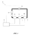
- FIG. 1 shows an explanatory diagram of the structure of a cooling system to which a cooling structure according to one embodiment of the present invention is applied.
- FIG. 2A is a cross-sectional view taken along the line I-I of FIG. 1 , showing the structure of an inverter included in the cooling system.
- FIG. 2B is an explanatory diagram of a flow contact surface of a cooler.
- FIG. 3 is a cross-sectional view taken along the line I-I of FIG. 2A .
- a cooling system A in one example includes a radiator 10, a water-cooling motor 11, a DC-CD converter 12, an inverter 20, an electric pump 13, and a controller B.
- the water-cooling motor 11, the DC-CD converter 12, the inverter 20 and the electric pump 13 are connected to the output side of the controller B to be appropriately controlled.
- the controller B includes a central processing unit (CPU), an interface circuit, and the like, and is adapted to exhibit a required function by execution of a predetermined program.
- CPU central processing unit
- interface circuit an interface circuit
- the inverter 20 is a power converter that electrically generates AC power from DC power.
- the inverter 20 includes a laminate formed by stacking a water jacket 21, a cooler 22, an electrically insulating material 23, a bus bar 24 made of copper or the like, a solder layer 25, a thermal buffer plate 26 made of copper, molybdenum etc., a solder layer 27, and a semiconductor chip 30 acting as a heat generating element in that order.
- a sidewall 21 d on a cooling fluid inlet side of the water jacket 21 is provided with an inlet 21e for inflow of the cooling fluid, whereas a sidewall 21f on a cooling fluid outlet side of the water jacket 21 is provided with an outlet 21 g for outflow of the cooling fluid.
- the water jacket 21 allows the cooling fluid to circulate therethrough via the above inlet 21e and outlet 21 g in the direction indicated by reference character " ⁇ " in FIGS. 1 and 2 .
- the cooler 22 is formed in a plate-like shape.
- a cooling structure according to one embodiment of the present invention is provided in a flow contact surface 22a facing the inside of the water jacket 21.
- the cooling structure in one embodiment of the present invention has a function of cooling a semiconductor chip 30 serving as the heat generating element by allowing the cooling fluid to flow and make contact with the cooler 22 which is a base material with the semiconductor chip 30 disposed thereon.
- the cooling structure is provided with a vortex-flow generating portion C1 extending in a direction ⁇ intersecting a circulation direction ⁇ of the cooling fluid and adapted to generate a vortex flow depending on the flow rate of the cooling fluid.
- the semiconductor chip 30 as the heat generating element is placed over the cooler 22 as the base material via the insulating material 23, bus bar 24, solder layer 25, buffer plate 26, and solder layer 27 described above.
- the buffer plate 26 is to buffer a difference in coefficient of linear expansion from the semiconductor chip 30.
- the vortex-flow generating portion C1 extends in the direction intersecting the circulation direction of the cooling fluid, and has a function of generating a vortex flow depending on the flow rate of the cooling fluid.
- a plurality of grooves 22b having a concave shape with a semicircular section are continuously formed at predetermined intervals on the flow contact surface 22a of the cooler 22 (see FIG. 2 ).
- the two adjacent grooves 22b and 22b are arranged by the predetermined interval, while adjacent inner walls for partitioning the grooves intersect each other so as to satisfy the following conditions.
- concave portions are continuously formed as used herein implies not only the arrangement in which the inner walls of the adjacent concave portions intersect each other, but also the form in which the inner walls of the adjacent concave portions do not intersect.
- the ends of the inner walls of the adjacent concave portions may be continuously connected together via a curved surface or the like.
- machine processing might be readily made.
- inner walls intersect means not only the state in which the inner peripheral wall surfaces of the grooves, whose concave portion has semicircular section, abut against each other on the flow contact surface, like when the grooves are arranged at certain intervals of the diameter of the concave portion, but also a state in which the grooves are arranged at intervals equal or less than the diameter of the concave portion. In this case, the inner peripheral wall surfaces of the adjacent grooves intersect at the flow contact face or thereunder.
- the sectional shape of the concave portion is not limited to be semicircular in section as mentioned above, and may be an irregular shape, or a combination of these shapes.
- the concave portion may be any recessed portion.
- predetermined intervals means not only the certain intervals, but also irregular intervals among all or parts of the concave portions.
- the cooling structure with the structure described above can have the following effects.
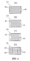
- FIG. 4A is an explanatory diagram of a vortex-flow generating portion in a first modified example
- FIG. 4B is an explanatory diagram of a vortex-flow generating portion according to a second modified example
- FIG. 4C is an explanatory diagram of a vortex-flow generating portion according to a third modified example
- FIG. 4D is an explanatory diagram of a vortex-flow generating portion according to a fourth modified example.
- the vortex-flow generating portion C2 of the first modified example, shown in FIG. 4A is provided with linear grooves 40 formed in an oblique manner at certain intervals in the circulation direction ⁇ of the cooling fluid.
- the vortex-flow generating portion C3 of the second modified example, shown in FIG. 4B is provided with grooves 41 formed perpendicular to the circulation direction ⁇ and in a zigzag manner at certain intervals.
- the vortex-flow generating portion C4 of the third modified example, shown in FIG. 4C is provided with wave-shaped grooves 42 formed perpendicular to the circulation direction ⁇ at certain intervals.
- the vortex-flow generating portion C5 of the fourth modified example, shown in FIG. 4D is provided with linear and discontinuous grooves 43 formed perpendicular to the circulation direction ⁇ at certain intervals.
- FIG. 5 is a diagram showing the heat transfer coefficient at the same loss in pressure with respect to a conventional fin shape.
- FIG. 6 is a diagram showing the rate of increase in heat transfer coefficient relative to an average heat transfer coefficient at respective flow rates of cooling fluid.
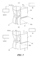
- FIG. 7A is a partial perspective view of the molding apparatus for the vortex-flow forming plate at the start of molding; and FIG. 7B is a partial perspective view of the molding apparatus for the vortex-flow forming plate upon completion of molding.
- FIG. 8A is a perspective view of a vortex-flow forming plate with the vortex-flow generating portion molded therein, and FIG. 8B is a plan view of a backside of a formation surface for the vortex-flow generating portion of the vortex-flow forming plate.
- a vortex-flow forming plate molding apparatus D molds the vortex-flow generating portions C1 (C2 to C5) described above and vortex-flow generating portions C6 to C8 to be described later in a vortex-flow forming plate 60 serving as a cooler.
- the vortex-flow forming plate molding apparatus D includes a vertically movable upper die 50 to form the vortex-flow generating portions C1 to C8, a fixed lower die 51, a sleeve 52 for pressing an outer peripheral edge 60a of the vortex-flow forming plate 60 (see FIG. 8 ) disposed between the upper die 50 and the lower die 51, and a back-pressure applicator 53, which applies a back pressure to between the sleeve 52 and the lower die 51.
- the vortex-flow forming plate 60 in this embodiment is formed of copper or a copper alloy with ductility. However, other ductile materials may be employed. By forming the vortex-flow forming plate 60 with copper or a copper alloy, the vortex-flow generating portion C can be readily molded.
- the outer peripheral edge 60a of the vortex-flow forming plate 60 is an outer region enclosing the vortex flow generating portion C1 (C2 to C8), as shown in FIG. 8A .
- the sleeve 52 is formed in a thick ring shape and comes in contact with the outer peripheral edge portion 60a.
- the back-pressure applicator 53 in this embodiment includes a hydraulic cylinder 54 for applying a back pressure, and a pressing member 55 for pressing the sleeve 52 by the hydraulic cylinder 54.
- the hydraulic cylinder 54 is connected to the output side of the controller (not shown), and thus is controlled to be driven to apply a predetermined back pressure to between the sleeve 52 and the lower die 51. Further, a hydraulic cylinder 56 is connected to the output side of the controller as well as the upper die 50, and thus is controlled to be appropriately driven.
- the outer peripheral edge 60a of the vortex-flow forming plate 60 disposed between the upper and lower dies 50 and 51 is pressed by applying a back pressure via the sleeve 52 and the lower die 51, and then the vortex-flow generating portion C is molded on the vortex-flow forming plate 60 by the upper and lower dies 50 and 51.
- FIG. 9 is a bar graph showing amounts of curvature at respective positions on the backside of the vortex-flow forming plate of the vortex-flow forming plate shown in FIG. 8B relative to the center of the plate.
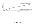
- FIG. 10 is a graph showing changes over time in back-pressure applied to between a sleeve and a lower die, and in molding load applied to between the upper and lower dies.
- the bar graph of FIG. 9 shows amounts of curvature in respective positions of the backside of the vortex-flow generating portion in the vortex-flow forming plate 60 shown in FIG. 8B , namely, "left upper”, “center upper”, “right upper”, “left middle”, “right middle”, “left lower”, “center lower”, and “right lower” with respect to the "middle center” thereof.
- a substantially constant back pressure is applied to between the sleeve 52 and the lower die 51 from the start of molding, whereas a load applied to between the upper and lower dies 50 and 51 is gradually increased.
- the amount of curvature of the vortex-flow forming plate 60 can be made 0.1 mm or less, as shown in FIG. 9 .
- the semiconductor or the like can be mounted as it is without applying an additional process, including reformation of the vortex-flow forming plate 60.
- FIGS. 11 to 13 are partial enlarged views of a convex portion formed between adjacent concave portions, wherein a tip of the convex portion is made curved surface with a certain curvature radius.
- FIGS. 11A and 11B to 13A and 13B each FIG. with A is a partial enlarged cross-sectional view of a molding part formed in the upper die for molding the vortex-flow generating portion
- each FIG. with B is an enlarged view of a vortex-flow generating portion of first to third other examples, which corresponds to the vortex-flow generating portion enclosed by the line II in FIG. 2 .
- the vortex-flow generating portion C6 in the first other example shown in FIG. 11B extends in the direction intersecting the circulation direction ⁇ of the cooling fluid, and has a function of generating a vortex flow depending on the flow rate of the cooling fluid.
- grooves 60b and convex portions 60c are continuously formed at certain intervals P1 on a flow contact surface 60d of the vortex flow forming plate 60.
- the grooves 60b are a plurality of concave portions having a semicircular section with a certain curvature radius, and the convex portions 60c have the same curvature radius as the groove 60b.
- a molding portion 50a of the upper die 50 shown in FIG. 11A has a convex portion 50c corresponding to the groove 60b, and a concave portion 50b corresponding to the convex portion 60c.
- the curvature radius of the convex portion 50c is set to the same as that of the concave portion 50b.
- Tip of the convex portion is a part contributing to molding of the vortex-flow generating portion C6.
- the curvature radius of the concave portion 50b of the upper die 50 is set to 0.2 mm or more, from the view point of wire cutting processing.
- grooves 60b' and convex portions 60c' are continuously formed at certain intervals P1' on a flow contact surface 60d of the vortex flow forming plate 60.
- the grooves 60b' are a plurality of concave portions having a semicircular section with a certain curvature radius, and the convex portions 60c' have larger curvature radius than the groove 60b'.
- the curvature radius of a convex portion 51c' corresponding to the groove 60b' is the same as that of a concave portion 50b' corresponding to the convex portion 60c'.
- grooves 60b" and convex portions 60c" are continuously formed at certain intervals P1" on a flow contact surface 60d of the vortex flow forming plate 60.
- the grooves 60b" are a plurality of concave portions having a semicircular section with a certain curvature radius, and the convex portions 60c" have larger curvature radius than the groove 60b".
- the curvature radius of a convex portion 51c" corresponding to the groove 60b" is the same as that of a concave portion 50b" corresponding to the convex portion 60c".
- the above embodiments describes the example of the cooling structure applied to an inverter, as an example of the cooling structure for cooling a heat generating element by allowing cooling fluid to circulate around a base material with the heat generating element disposed thereon.
- the present invention may be directly applied to a motor or the like as the heat generating element.
Landscapes
- Engineering & Computer Science (AREA)
- Microelectronics & Electronic Packaging (AREA)
- Physics & Mathematics (AREA)
- Thermal Sciences (AREA)
- Mechanical Engineering (AREA)
- General Engineering & Computer Science (AREA)
- Cooling Or The Like Of Semiconductors Or Solid State Devices (AREA)
- Cooling Or The Like Of Electrical Apparatus (AREA)
Abstract
Description
- The present invention relates to a cooling structure for cooling electronic devices, such as a semiconductor or a motor, a vortex-flow forming plate molding apparatus, and a method for molding a vortex-flow generating portion.
- This kind of technology in the prior art includes a "cooling device" as disclosed in
Patent Literature 1. The cooling device disclosed inPatent Literature 1 includes a plurality of heat dissipation members extending in the direction away from an electronic component. Cooling fluid is allowed to pass through between the respective heat dissipation members, thereby cooling the electronic component. The heat dissipation member is designed to have its length decreased as the heat transfer temperature of heat generated by the electronic component becomes lower. - It is described that the heat dissipation members are formed to become shorter from the center of the electric component toward the end thereof and along the flow direction of the cooling fluid.
- [Patent Literature 1]: Japanese Patent Unexamined Publication No.
2003-8264 - However, the cooling device disclosed in the
above Patent Literature 1 includes the heat dissipation members extending in the direction away from the electronic component, and is designed to cool the electronic component by increasing a flow contact area with the heat dissipation member, which might inhibit reduction in size of the cooling device. - Accordingly, it is an object of the present invention to provide a cooling structure, a molding apparatus for a vortex-flow forming plate, and a method for molding a vortex-flow forming plate that can reduce a loss in pressure and improve the heat conductivity while reducing its size.
- In order to solve the foregoing problems, a cooling structure according to the present invention is adapted to cool an electronic component by allowing a cooling fluid to circulate around the heat generating element or a base material with the heat generating element disposed thereon. The cooling structure includes a vortex-flow generating portion, which extends in a direction intersecting a circulation direction of the cooling fluid, and which generates a vortex flow in accordance with a flow rate of the cooling fluid.
- In order to solve the above problems, a vortex-flow forming plate molding apparatus according to the present invention is adapted to mold a vortex-flow generating portion on a vortex-flow forming plate.
- In the present invention, the molding apparatus includes: a vertically movable upper die to form the vortex-flow generating portion; a fixed lower die; a sleeve for pressing an outer peripheral edge of the vortex-flow forming plate disposed between the upper die and the lower die; and a back-pressure applicator, which applies a back pressure to between the sleeve and the lower die. The outer peripheral edge of the vortex-flow forming plate is pressed via the back pressure applied by the sleeve and the lower die, and the vortex-flow generating portion is molded on the vortex-flow forming plate by the upper die and the lower die.
- In order to solve the above problems, a method for molding a vortex-flow generating portion according to the present invention uses the molding apparatus for the vortex-flow forming plate as described above.
- In the present invention, the outer peripheral edge of the vortex-flow forming plate, disposed between the upper die and the lower die, is pressed by applying the back pressure via the sleeve and the lower die, and the vortex-flow generating portion is molded on the vortex-flow forming plate by the upper die and the lower die.
- According to the present invention, the vortex-flow generating portion is provided which extends in the direction intersecting the circulation direction of the cooling fluid, and which generates a vortex flow depending on the flow rate of the cooling fluid. Therefore, reduction of a loss in pressure and improvement of the heat conductivity is achieved, while reducing the size and simplifying the structure.
-
-
FIG. 1 is an explanatory diagram showing the structure of a cooling system to which a cooling structure according to one embodiment of the present invention is applied. -
FIG. 2A is a cross-sectional view taken along the line I-I ofFIG. 1 , showing the structure of an inverter included in the cooling system, andFIG. 2B is an explanatory diagram of a flow contact surface of a cooler. -
FIG. 3 is a cross-sectional view taken along the line II-II ofFIG. 2A . -
FIG. 4A is an explanatory diagram showing a vortex-flow generating portion according to a first modified example,FIG. 4B is an explanatory diagram showing a vortex-flow generating portion according to a second modified example,FIG. 4C is an explanatory diagram showing a vortex-flow generating portion according to a third modified example, andFIG. 4D is an explanatory diagram showing a vortex-flow generating portion according to a fourth modified example. -
FIG. 5 is a diagram showing the heat transfer coefficient at the same loss in pressure with respect to a conventional fin shape. -
FIG. 6 is a diagram showing the rate of increase in heat transfer coefficient relative to an average heat transfer coefficient at respective flow rates of cooling fluid. -
FIG. 7A is a partial perspective view of a molding apparatus for a vortex-flow forming plate at the start of molding, andFIG. 7B is a partial perspective view of the molding apparatus for a vortex-flow forming plate upon completion of molding. -
FIG. 8A is a perspective view of a vortex-flow forming plate with a vortex-flow generating portion molded therein, andFIG. 8B is a plan view of a backside of a formation surface for the vortex-flow generating portion of the vortex-flow forming plate. -
FIG. 9 is a bar graph showing amounts of curvature at respective positions on the backside of the vortex-flow forming plate shown inFIG. 8B relative to the center of the plate. -
FIG. 10 is a graph showing changes over time in back-pressure applied to between a sleeve and a lower die, and in molding load applied to between the upper and lower dies. -
FIG. 11A is a partial enlarged cross-sectional view of a molding part formed in the upper die for molding the vortex-flow generating portion, andFIG. 11B is an enlarged view of a vortex-flow generating portion in a first other example corresponding to the part of the vortex-flow generating portion enclosed by a line III inFIG. 2 . -
FIG. 12A is a partial enlarged cross-sectional view of a molding part formed in an upper die for molding the vortex-flow generating portion, andFIG. 12B is an enlarged view of a vortex-flow generating portion in a second other example corresponding to the part of the vortex-flow generating portion enclosed by a line III inFIG. 2 . -
FIG. 13A is a partial enlarged cross-sectional view of a molding part formed in an upper die for molding the vortex-flow generating portion, andFIG. 13B is an enlarged view of a vortex-flow generating portion in a third other example corresponding to the part of the vortex-flow generating portion enclosed by the line III inFIG. 2 . - In the following, embodiments of the present invention will be described with reference to the accompanying drawings.
FIG. 1 shows an explanatory diagram of the structure of a cooling system to which a cooling structure according to one embodiment of the present invention is applied.FIG. 2A is a cross-sectional view taken along the line I-I ofFIG. 1 , showing the structure of an inverter included in the cooling system.FIG. 2B is an explanatory diagram of a flow contact surface of a cooler.FIG. 3 is a cross-sectional view taken along the line I-I ofFIG. 2A . - As shown in
FIG. 1 , a cooling system A in one example includes aradiator 10, a water-coolingmotor 11, a DC-CD converter 12, aninverter 20, anelectric pump 13, and a controller B. - The water-cooling
motor 11, the DC-CD converter 12, theinverter 20 and theelectric pump 13 are connected to the output side of the controller B to be appropriately controlled. - The controller B includes a central processing unit (CPU), an interface circuit, and the like, and is adapted to exhibit a required function by execution of a predetermined program.
- In this embodiment, the
inverter 20 is a power converter that electrically generates AC power from DC power. As shown inFIG. 2A , theinverter 20 includes a laminate formed by stacking awater jacket 21, a cooler 22, an electrically insulatingmaterial 23, abus bar 24 made of copper or the like, asolder layer 25, athermal buffer plate 26 made of copper, molybdenum etc., asolder layer 27, and asemiconductor chip 30 acting as a heat generating element in that order. - A
sidewall 21 d on a cooling fluid inlet side of thewater jacket 21 is provided with aninlet 21e for inflow of the cooling fluid, whereas asidewall 21f on a cooling fluid outlet side of thewater jacket 21 is provided with anoutlet 21 g for outflow of the cooling fluid. - The
water jacket 21 allows the cooling fluid to circulate therethrough via theabove inlet 21e andoutlet 21 g in the direction indicated by reference character "α" inFIGS. 1 and2 . - The cooler 22 is formed in a plate-like shape. A cooling structure according to one embodiment of the present invention is provided in a
flow contact surface 22a facing the inside of thewater jacket 21. - The cooling structure in one embodiment of the present invention has a function of cooling a
semiconductor chip 30 serving as the heat generating element by allowing the cooling fluid to flow and make contact with the cooler 22 which is a base material with thesemiconductor chip 30 disposed thereon. The cooling structure is provided with a vortex-flow generating portion C1 extending in a direction β intersecting a circulation direction α of the cooling fluid and adapted to generate a vortex flow depending on the flow rate of the cooling fluid. - In this embodiment, the
semiconductor chip 30 as the heat generating element is placed over the cooler 22 as the base material via the insulatingmaterial 23,bus bar 24,solder layer 25,buffer plate 26, andsolder layer 27 described above. - The
buffer plate 26 is to buffer a difference in coefficient of linear expansion from thesemiconductor chip 30. - The vortex-flow generating portion C1 extends in the direction intersecting the circulation direction of the cooling fluid, and has a function of generating a vortex flow depending on the flow rate of the cooling fluid.
- In this embodiment, a plurality of
grooves 22b having a concave shape with a semicircular section are continuously formed at predetermined intervals on theflow contact surface 22a of the cooler 22 (seeFIG. 2 ). - In this embodiment, the two
adjacent grooves - The expression "concave portions are continuously formed" as used herein implies not only the arrangement in which the inner walls of the adjacent concave portions intersect each other, but also the form in which the inner walls of the adjacent concave portions do not intersect.
- In the case of the form in which the inner walls of the adjacent concave portions do not intersect, the ends of the inner walls of the adjacent concave portions may be continuously connected together via a curved surface or the like. When the inner wall ends of the adjacent concave portions are smoothly connected to each other via the curved surface or the like, machine processing might be readily made.
- The expression "inner walls intersect" as used herein means not only the state in which the inner peripheral wall surfaces of the grooves, whose concave portion has semicircular section, abut against each other on the flow contact surface, like when the grooves are arranged at certain intervals of the diameter of the concave portion, but also a state in which the grooves are arranged at intervals equal or less than the diameter of the concave portion. In this case, the inner peripheral wall surfaces of the adjacent grooves intersect at the flow contact face or thereunder.
- The sectional shape of the concave portion is not limited to be semicircular in section as mentioned above, and may be an irregular shape, or a combination of these shapes.
- That is, as long as the concave portion generates the vortex flow according to the flow rate of the cooling fluid, it may be any recessed portion.
- The term "predetermined intervals" as used herein means not only the certain intervals, but also irregular intervals among all or parts of the concave portions.
- By forming the two
adjacent grooves more grooves 22b can be formed, thereby more vortex flows can be generated. - (1) A maximum height H of the groove (concave portion) 22b (see
FIG. 2 ) is set larger than a thickness δb of a laminar sublayer in vicinity of a wall surface which is calculated from a Reynolds number Re and a representative length d as fluidization conditions by the following formula: δb = 63.5/(Re7/8) × d. - (2) W+ = Wuτ/ν is set within a range of 25 to 300, wherein W+ = Wuτ/ν is a value given by nondimensionalizing an opening width W of the
groove 22b by using a shear rate of uτ = (τω/ρ)1/2 calculated from a shear stress τω and a fluid density p; an experimental formula of a pipe friction coefficient represented by Cf = τω / (0.5ρu2) = 0.73 Re-0.25 calculated from a flow rate u, a density p, and the Reynolds number Re; and a kinetic viscosity ν. - (3) The maximum height H of the
groove 22b is set smaller than a distance X from the flow contact surface to a flow passage surface opposed thereto (bottom wall surface 21 c). - (4) The representative length d = 4A/L calculated by a minimum flow passage sectional area A and a maximum wetted perimeter length L of a flow passage section perpendicular to the circulation direction of the cooling fluid is set large.
The minimum flow passage sectional area A is a sectional area partitioned by outlines L1, L2, L3, and L4 shown inFIG. 3 .
The outlines L1 and L3 have the same length as a distance between thebottom wall surface 21c and a top part of theconvex portion 22c. The outlines L2 and L4 have the same length as thegroove 22b.
The term "wetted perimeter length L" as used herein is a length of the outline of the section of the flow passage partitioned by the outlines L5, L6, L7, and L8 in contact with the cooling fluid (shown inFIG. 3 ).
The outlines L5 and L7 have the same length as a distance between thebottom wall surface 21c and a bottom part of theconcave portion 22b. The outlines L6 and L8 have the same length as theconcave portion 22b. - (5) The representative length d = 4A/L is set to 0.004 or more. Preferably, the representative length d = 4A/L is set to 0.007 or more.
- (6) The dimensionless width W+ is set in a range from 40 to 150, wherein W+ is a value given by nondimesionalizing a width of a back part of the
groove 22b in the direction β, which is perpendicular to the circulation direction α of the cooling fluid. - (7) The length of the convex portion with respect to the circulation direction α of the cooling fluid becomes smaller towards the tip end of the convex portion, and the area of the tip end of the convex portion, which is flat with respect to a flow direction, is small, and the concave and convex shape is continuous with respect to the flow direction of the cooling fluid.
- The cooling structure with the structure described above can have the following effects.
- The cooling structure is provided with a vortex-flow generating portion, which extends in the direction intersecting the circulation direction of the cooling fluid, and which generates a vortex flow according to a flow rate of the cooling fluid. Therefore, the vortex flow generated by the vortex-flow generating portion can stir the cooling fluid in the vicinity of the heat generating element or the base material with the heat generating element disposed thereon to promote the heat transfer.
- The maximum height H of the groove (concave portion) 22b is set larger than a thickness δb of a laminar sublayer in the vicinity of a wall surface calculated from a Reynolds number Re and a representative length d as fluidization conditions by the following formula: δb = 63.5/(Re7/8) × d. Thus, the heat transfer can be promoted in a thickness of the laminar sublayer or more in the vicinity of the heat generating element or the base material with the heat generating element disposed thereon.
- W+ = Wuτ/ν is set within a range of 25 to 300, wherein W+ = Wuτ/ν is a value given by nondimensionalizing an opening width W of the
groove 22b by using a shear rate of uτ = (τω/ρ)1/2 calculated from a shear stress τω and a fluid density p; an experimental formula of a pipe friction coefficient represented by Cf = τω / (0.5ρu2) = 0.73 Re--0.25 calculated from a flow rate u, a density p, and the Reynolds number Re; and a kinetic viscosity ν. Thus, improvement of the heat transfer efficiency can be achieved. - The representative length d = 4A/L is set to 0.004 or more, wherein A is the minimum flow passage sectional area and L is the maximum wetted perimeter length of the flow passage section perpendicular to the circulation direction of the cooling fluid. Therefore, a shearing force of a wall surface is reduced, thereby suppressing the increase in loss of pressure.
- By forming the groove to intersect the circulation direction of the cooling fluid, the vortex flow is formed in the entire region of the flow contact surface, which intersects the above circulation direction, thereby promoting the heat transfer.
- By setting the width of the groove, which has an opening on the surface where the cooling fluid flows, to a predetermined value, further improvement of the heat transfer performance is achieved.
- By continuously forming the groove in the direction perpendicular to the circulation direction of the cooling fluid, the frequency of vortex flow occurrence with respect to the circulation direction is increased, thereby promoting the heat transfer.
- The groove is provided in a concave shape at the flow contact surface of the cooler, which can further reduce the size of the heat generating element or base material to which the cooling structure is applied.
- Next, a modified example of the vortex-flow generating portion will be described with reference to
FIGS. 4A to 4D. FIG. 4A is an explanatory diagram of a vortex-flow generating portion in a first modified example,FIG. 4B is an explanatory diagram of a vortex-flow generating portion according to a second modified example,FIG. 4C is an explanatory diagram of a vortex-flow generating portion according to a third modified example, andFIG. 4D is an explanatory diagram of a vortex-flow generating portion according to a fourth modified example. - The vortex-flow generating portion C2 of the first modified example, shown in
FIG. 4A , is provided withlinear grooves 40 formed in an oblique manner at certain intervals in the circulation direction α of the cooling fluid. - The vortex-flow generating portion C3 of the second modified example, shown in
FIG. 4B , is provided withgrooves 41 formed perpendicular to the circulation direction α and in a zigzag manner at certain intervals. - The vortex-flow generating portion C4 of the third modified example, shown in
FIG. 4C , is provided with wave-shapedgrooves 42 formed perpendicular to the circulation direction α at certain intervals. - The vortex-flow generating portion C5 of the fourth modified example, shown in
FIG. 4D , is provided with linear anddiscontinuous grooves 43 formed perpendicular to the circulation direction α at certain intervals. -
FIG. 5 is a diagram showing the heat transfer coefficient at the same loss in pressure with respect to a conventional fin shape. -
FIG. 6 is a diagram showing the rate of increase in heat transfer coefficient relative to an average heat transfer coefficient at respective flow rates of cooling fluid. - As can be seen from
FIG. 5 , there is a width of a groove that improves the heat transfer performance for a conventional fin under the same loss in pressure. - Further, as can be seen from
FIG. 6 , there is an optical range of W+ with respect to the heat transfer coefficient of the orthogonal groove at the same flow rate. - The above-mentioned vortex-flow generating portion is molded by the molding apparatus for the vortex-flow forming plate shown in
FIGS. 7A and 7B. FIG. 7A is a partial perspective view of the molding apparatus for the vortex-flow forming plate at the start of molding; andFIG. 7B is a partial perspective view of the molding apparatus for the vortex-flow forming plate upon completion of molding.FIG. 8A is a perspective view of a vortex-flow forming plate with the vortex-flow generating portion molded therein, andFIG. 8B is a plan view of a backside of a formation surface for the vortex-flow generating portion of the vortex-flow forming plate. - A vortex-flow forming plate molding apparatus D molds the vortex-flow generating portions C1 (C2 to C5) described above and vortex-flow generating portions C6 to C8 to be described later in a vortex-
flow forming plate 60 serving as a cooler. - The vortex-flow forming plate molding apparatus D includes a vertically movable
upper die 50 to form the vortex-flow generating portions C1 to C8, a fixed lower die 51, asleeve 52 for pressing an outerperipheral edge 60a of the vortex-flow forming plate 60 (seeFIG. 8 ) disposed between theupper die 50 and thelower die 51, and a back-pressure applicator 53, which applies a back pressure to between thesleeve 52 and thelower die 51. - The vortex-
flow forming plate 60 in this embodiment is formed of copper or a copper alloy with ductility. However, other ductile materials may be employed. By forming the vortex-flow forming plate 60 with copper or a copper alloy, the vortex-flow generating portion C can be readily molded. - "The outer
peripheral edge 60a of the vortex-flow forming plate 60" is an outer region enclosing the vortex flow generating portion C1 (C2 to C8), as shown inFIG. 8A . - The
sleeve 52 is formed in a thick ring shape and comes in contact with the outerperipheral edge portion 60a. - The back-
pressure applicator 53 in this embodiment includes ahydraulic cylinder 54 for applying a back pressure, and a pressingmember 55 for pressing thesleeve 52 by thehydraulic cylinder 54. - The
hydraulic cylinder 54 is connected to the output side of the controller (not shown), and thus is controlled to be driven to apply a predetermined back pressure to between thesleeve 52 and thelower die 51. Further, ahydraulic cylinder 56 is connected to the output side of the controller as well as theupper die 50, and thus is controlled to be appropriately driven. - According to a molding method for molding the vortex-flow generating portion using the vortex-flow forming plate molding apparatus D with the above-mentioned structure, the outer
peripheral edge 60a of the vortex-flow forming plate 60 disposed between the upper and lower dies 50 and 51 is pressed by applying a back pressure via thesleeve 52 and thelower die 51, and then the vortex-flow generating portion C is molded on the vortex-flow forming plate 60 by the upper and lower dies 50 and 51. -
FIG. 9 is a bar graph showing amounts of curvature at respective positions on the backside of the vortex-flow forming plate of the vortex-flow forming plate shown inFIG. 8B relative to the center of the plate.FIG. 10 is a graph showing changes over time in back-pressure applied to between a sleeve and a lower die, and in molding load applied to between the upper and lower dies. - The bar graph of
FIG. 9 shows amounts of curvature in respective positions of the backside of the vortex-flow generating portion in the vortex-flow forming plate 60 shown inFIG. 8B , namely, "left upper", "center upper", "right upper", "left middle", "right middle", "left lower", "center lower", and "right lower" with respect to the "middle center" thereof. - As shown in
FIG. 10 , a substantially constant back pressure is applied to between thesleeve 52 and thelower die 51 from the start of molding, whereas a load applied to between the upper and lower dies 50 and 51 is gradually increased. - By molding the vortex-flow generating portions C1 (C2 to C8), while the outer
peripheral edge 60a of the vortex-flow forming plate 60 is pressed by thelower die 51 and thesleeve 52 with the substantially constant back pressure as described above, the amount of curvature of the vortex-flow forming plate 60 can be made 0.1 mm or less, as shown inFIG. 9 . - Thus, the semiconductor or the like can be mounted as it is without applying an additional process, including reformation of the vortex-
flow forming plate 60. - Next, a description will be given of other forms of a convex portion formed between adjacent concave portions with reference to
FIGS. 11 to 13. FIGS. 11 to 13 are partial enlarged views of a convex portion formed between adjacent concave portions, wherein a tip of the convex portion is made curved surface with a certain curvature radius. AmongFIGS. 11A and11B to 13A and13B , each FIG. with A is a partial enlarged cross-sectional view of a molding part formed in the upper die for molding the vortex-flow generating portion, and each FIG. with B is an enlarged view of a vortex-flow generating portion of first to third other examples, which corresponds to the vortex-flow generating portion enclosed by the line II inFIG. 2 . - The vortex-flow generating portion C6 in the first other example shown in
FIG. 11B extends in the direction intersecting the circulation direction α of the cooling fluid, and has a function of generating a vortex flow depending on the flow rate of the cooling fluid. - In this embodiment,
grooves 60b andconvex portions 60c are continuously formed at certain intervals P1 on aflow contact surface 60d of the vortexflow forming plate 60. Thegrooves 60b are a plurality of concave portions having a semicircular section with a certain curvature radius, and theconvex portions 60c have the same curvature radius as thegroove 60b. - In this case, a
molding portion 50a of theupper die 50 shown inFIG. 11A has aconvex portion 50c corresponding to thegroove 60b, and aconcave portion 50b corresponding to theconvex portion 60c. The curvature radius of theconvex portion 50c is set to the same as that of theconcave portion 50b. - "Tip of the convex portion" is a part contributing to molding of the vortex-flow generating portion C6.
- It is preferred that the curvature radius of the
concave portion 50b of theupper die 50 is set to 0.2 mm or more, from the view point of wire cutting processing. - Inthe vortex-flow generating portion C7 in the second other example shown in
FIG. 12B ,grooves 60b' andconvex portions 60c' are continuously formed at certain intervals P1' on aflow contact surface 60d of the vortexflow forming plate 60. Thegrooves 60b' are a plurality of concave portions having a semicircular section with a certain curvature radius, and theconvex portions 60c' have larger curvature radius than thegroove 60b'. - In this case, in the
molding portion 50a of theupper die 50 shown inFIG. 12A , the curvature radius of a convex portion 51c' corresponding to thegroove 60b' is the same as that of aconcave portion 50b' corresponding to theconvex portion 60c'. - In the vortex-flow generating portion C8 in the third other example shown in
FIG. 13B ,grooves 60b" andconvex portions 60c" are continuously formed at certain intervals P1" on aflow contact surface 60d of the vortexflow forming plate 60. Thegrooves 60b" are a plurality of concave portions having a semicircular section with a certain curvature radius, and theconvex portions 60c" have larger curvature radius than thegroove 60b". - In this case, in the
molding portion 50a of thelower die 50 shown inFIG. 13A , the curvature radius of a convex portion 51c" corresponding to thegroove 60b" is the same as that of aconcave portion 50b" corresponding to theconvex portion 60c". - With the vortex-flow generating portion described in
FIGS. 7 to 13 , the following effects can be obtained, in addition to the effects described above. - By forming the tip of the convex portion formed between the adjacent concave portions in a curved surface having a certain curvature radius, wear caused by erosion can be suppressed, and the vortex-flow generating portion can be readily processed.
Further, the occurrence of cracks or breakage in the die can be suppressed. Since the tip of the convex portion has no corner or edge, when an anti-rust coating is formed over the surface of the vortex-flow generating portion, the average thickness of the anti-rust coating can be easily controlled. - The present invention is not limited to the embodiments described above, and various modifications and changes mentioned below can be made.
- The above embodiments describes the example of the cooling structure applied to an inverter, as an example of the cooling structure for cooling a heat generating element by allowing cooling fluid to circulate around a base material with the heat generating element disposed thereon. However, it is needless to say that the present invention may be directly applied to a motor or the like as the heat generating element.
-
- 22
- Base material (cooler)
- 30
- Heat generating element
- 50
- Upper die
- 51
- Lower die
- 52
- Sleeve
- 53
- Back-pressure applicator
- 60
- Vortex-flow forming plate
- 60a
- Outer peripheral edge
- 60c, 60c', 60c"
- Convex portion
- C1 to C8
- Vortex-flow generating portion
Claims (16)
- A cooling structure to cool a heat generating element by allowing a cooling fluid to flow and come into contact with the heat generating element or a base material with the heat generating element disposed thereon, comprising:a vortex-flow generating portion, which extends in a direction intersecting a circulation direction of the cooling fluid, and which generates a vortex flow in accordance with a flow rate of the cooling fluid.
- The cooling structure according to claim 1, wherein
the vortex-flow generating portion includes a plurality of concave portions arranged at predetermined intervals. - The cooling structure according to claim 2, wherein
a maximum height H of the concave portion is set larger than a thickness δb of a laminar sublayer in the vicinity of a wall surface, calculated from a Reynolds number Re and a representative length d as fluidization conditions by the following formula: δ6 = 63.5/(Re7/8) × d. - The cooling structure according to claim 2 or 3, whereinW+ = Wuτ/ν is set within a range of 25 to 300, wherein W+ = Wuτ/ν is a value given by nondimensionalizing an opening width W of the concave portion by using a shear rate of uτ = (τω/ρ)1/2 calculated from a shear stress τω and a fluid density p; an experimental formula of a pipe friction coefficient, represented by Cf = τω / (0.5ρu2) = 0.73 Re--0.25 calculated from a flow rate u, a density p, and the Reynolds number Re; and a kinetic viscosity v.
- The cooling structure according to claim 4, wherein
the maximum height H of the concave portion is set smaller than a distance X from an opening surface of the concave portion to a flow passage surface facing the opening surface. - The cooling structure according to claim 5, wherein
a representative length d = 4A/L is set to 0.004 or more, wherein A is minimum flow passage sectional area and L is maximum wetted perimeter length of the flow passage section perpendicular to the circulation direction of the cooling fluid. - The cooling structure according to claim 6, wherein
the representative length d = 4A/L is set to 0.007 or more, wherein A is the minimum flow passage sectional area and L is the maximum wetted perimeter length of the flow passage section perpendicular to the circulation direction of the cooling fluid. - The cooling structure according to claim 6 or 7, wherein
dimensionless width W+ is set in a range from 40 to 150, wherein W+ is a value given by nondimesionalizing a width of the concave portion in the direction perpendicular to the circulation direction of the cooling fluid. - The cooling structure according to any one of claims 2 to 8, wherein
the two adjacent concave portions are formed such that inner walls for partitioning the adjacent concave portions intersect each other. - The cooling structure according to any one of claims 1 to 10, wherein
the vortex-flow generating portion is a groove formed in a concave shape on a flow contact surface, which comes in contact with flow of the cooling fluid for cooling the heat generating element or the base material with the heat generating element disposed thereon. - The cooling structure according to any one of claims 2 to 10, wherein
the concave portion has a semicircular sectional shape. - The cooling structure according to any one of claims 1 to 11, wherein
a tip of the convex portion formed between the adjacent concave portions is formed in a curved surface with a certain curvature radius. - The cooling structure according to claim 12, wherein
the curvature radius of the tip of the convex portion is 0.2 mm or more. - The cooling structure according to any one of claims 1 to 13, wherein
the vortex-flow generating portion is molded on a vortex-flow forming plate made of copper or a copper alloy. - A vortex-flow forming plate molding apparatus for molding the vortex-flow generating portion according to claim 14 on a vortex-flow forming plate, comprising:a vertically movable upper die to form the vortex-flow generating portion;a fixed lower die;a sleeve for pressing an outer peripheral edge of the vortex-flow forming plate disposed between the upper die and the lower die; anda back-pressure applicator for applying a back pressure to between the sleeve and the lower die, whereinthe outer peripheral edge of the vortex-flow forming plate is pressed by the sleeve and the lower die, the back pressure being applied on the sleeve and the lower die, andthe vortex-flow generating portion is molded on the vortex-flow forming plate by the upper die and the lower die.
- A method for molding a vortex-flow generating portion using the vortex-flow forming plate molding apparatus according to claim 15, wherein
the outer peripheral edge of the vortex-flow forming plate, disposed between the upper die and the lower die, is pressed by the sleeve and the lower die, the back pressure being applied on the sleeve and the lower die, and
the vortex-flow generating portion is molded on the vortex-flow forming plate by the upper die and the lower.
Applications Claiming Priority (3)
| Application Number | Priority Date | Filing Date | Title |
|---|---|---|---|
| JP2012089202 | 2012-04-10 | ||
| JP2013042572 | 2013-03-05 | ||
| PCT/JP2013/057472 WO2013153914A1 (en) | 2012-04-10 | 2013-03-15 | Cooling structure, vortex-flow forming plate molding apparatus, and method of molding vortex-flow generating unit |
Publications (3)
| Publication Number | Publication Date |
|---|---|
| EP2838329A1 true EP2838329A1 (en) | 2015-02-18 |
| EP2838329A4 EP2838329A4 (en) | 2015-04-29 |
| EP2838329B1 EP2838329B1 (en) | 2018-05-23 |
Family
ID=49327488
Family Applications (1)
| Application Number | Title | Priority Date | Filing Date |
|---|---|---|---|
| EP13775403.2A Active EP2838329B1 (en) | 2012-04-10 | 2013-03-15 | Cooling structure, vortex-flow forming plate molding apparatus, and method for molding vortex-flow generating portion |
Country Status (5)
| Country | Link |
|---|---|
| US (1) | US9243855B2 (en) |
| EP (1) | EP2838329B1 (en) |
| JP (1) | JP5871197B2 (en) |
| CN (1) | CN104206041B (en) |
| WO (1) | WO2013153914A1 (en) |
Cited By (1)
| Publication number | Priority date | Publication date | Assignee | Title |
|---|---|---|---|---|
| EP3054479A4 (en) * | 2013-10-02 | 2016-10-26 | Nissan Motor | THERMAL RADIATION SYSTEM |
Families Citing this family (4)
| Publication number | Priority date | Publication date | Assignee | Title |
|---|---|---|---|---|
| JP6344109B2 (en) * | 2014-07-22 | 2018-06-20 | 日産自動車株式会社 | Molding device for concave and convex molded products |
| CA2978795A1 (en) * | 2015-03-16 | 2016-09-22 | Dana Canada Corporation | Heat exchangers with plates having surface patterns for enhancing flatness and methods for manufacturing same |
| CN110893074B (en) * | 2018-09-12 | 2025-05-02 | 武汉苏泊尔炊具有限公司 | Pot body, pot body processing method and cooking utensil |
| JP7807283B2 (en) * | 2022-03-31 | 2026-01-27 | 本田技研工業株式会社 | Water jacket and method of manufacturing the water jacket |
Family Cites Families (19)
| Publication number | Priority date | Publication date | Assignee | Title |
|---|---|---|---|---|
| DE3137034A1 (en) * | 1981-09-17 | 1983-03-24 | Siemens AG, 1000 Berlin und 8000 München | METHOD AND DEVICE FOR EXCHANGING HEAT ON SOLID SURFACES |
| US4989070A (en) * | 1988-11-10 | 1991-01-29 | Coriolis Corporation | Modular heat sink structure |
| US5111280A (en) * | 1988-11-10 | 1992-05-05 | Iversen Arthur H | Thermal management of power conditioning systems |
| US5001548A (en) * | 1989-03-13 | 1991-03-19 | Coriolis Corporation | Multi-chip module cooling |
| US5003376A (en) * | 1989-03-28 | 1991-03-26 | Coriolis Corporation | Cooling of large high power semi-conductors |
| US4984066A (en) * | 1989-12-12 | 1991-01-08 | Coriolis Corporation | Cooling of large semi-conductor devices |
| US5239200A (en) * | 1991-08-21 | 1993-08-24 | International Business Machines Corporation | Apparatus for cooling integrated circuit chips |
| JP2003008264A (en) | 2001-06-26 | 2003-01-10 | Nissan Motor Co Ltd | Electronic component cooling system |
| US6867973B2 (en) * | 2003-03-05 | 2005-03-15 | Shyy-Woei Chang | Heat dissipation device with liquid coolant |
| TW200503608A (en) * | 2003-07-15 | 2005-01-16 | Ind Tech Res Inst | Cooling plate having vortices generator |
| JP4027353B2 (en) * | 2004-09-28 | 2007-12-26 | 三菱電機株式会社 | Cooling structure |
| US7204299B2 (en) * | 2004-11-09 | 2007-04-17 | Delphi Technologies, Inc. | Cooling assembly with sucessively contracting and expanding coolant flow |
| JP4305406B2 (en) * | 2005-03-18 | 2009-07-29 | 三菱電機株式会社 | Cooling structure |
| US7578337B2 (en) * | 2005-04-14 | 2009-08-25 | United States Thermoelectric Consortium | Heat dissipating device |
| JP2008071800A (en) * | 2006-09-12 | 2008-03-27 | Mitsubishi Electric Corp | Heat sink, cooling structure and heat sink |
| JP5129942B2 (en) * | 2006-10-03 | 2013-01-30 | トヨタ自動車株式会社 | Semiconductor device |
| JP4989574B2 (en) * | 2008-07-10 | 2012-08-01 | 株式会社日本自動車部品総合研究所 | Heat sink for semiconductor element cooling |
| US8496048B2 (en) * | 2010-01-25 | 2013-07-30 | Qualitics, Inc. | Vortical boiling phenomenon based water cooling block |
| TWM422285U (en) * | 2011-09-21 | 2012-02-01 | Enermax Technology Corp | Liquid-cooling type improved heat exchange module |
-
2013
- 2013-03-15 CN CN201380018036.6A patent/CN104206041B/en active Active
- 2013-03-15 JP JP2014510092A patent/JP5871197B2/en active Active
- 2013-03-15 US US14/390,667 patent/US9243855B2/en active Active
- 2013-03-15 WO PCT/JP2013/057472 patent/WO2013153914A1/en not_active Ceased
- 2013-03-15 EP EP13775403.2A patent/EP2838329B1/en active Active
Cited By (2)
| Publication number | Priority date | Publication date | Assignee | Title |
|---|---|---|---|---|
| EP3054479A4 (en) * | 2013-10-02 | 2016-10-26 | Nissan Motor | THERMAL RADIATION SYSTEM |
| US9964366B2 (en) | 2013-10-02 | 2018-05-08 | Nissan Motor Co., Ltd. | Heat-radiating system |
Also Published As
| Publication number | Publication date |
|---|---|
| JP5871197B2 (en) | 2016-03-01 |
| CN104206041A (en) | 2014-12-10 |
| CN104206041B (en) | 2016-08-17 |
| WO2013153914A1 (en) | 2013-10-17 |
| JPWO2013153914A1 (en) | 2015-12-17 |
| EP2838329A4 (en) | 2015-04-29 |
| EP2838329B1 (en) | 2018-05-23 |
| US20150168084A1 (en) | 2015-06-18 |
| US9243855B2 (en) | 2016-01-26 |
Similar Documents
| Publication | Publication Date | Title |
|---|---|---|
| EP2838329B1 (en) | Cooling structure, vortex-flow forming plate molding apparatus, and method for molding vortex-flow generating portion | |
| EP2704191B1 (en) | Cooler for semiconductor module | |
| JP5900506B2 (en) | Semiconductor module cooler and semiconductor module | |
| JP5565459B2 (en) | Semiconductor module and cooler | |
| KR20100087377A (en) | Cooling fin and manufacturing method of the cooling fin | |
| US20120012295A1 (en) | Heat exchanger and method of manufacturing the same | |
| EP3054479B1 (en) | Heat-radiating system | |
| CN110637363A (en) | Radiator and method for producing the same | |
| CN102549743A (en) | Semiconductor module and cooling unit | |
| CN103096690A (en) | Heat sink | |
| CN104918729A (en) | Method for producing cooling device and heat-dissipating member | |
| WO2016047335A1 (en) | Electronic component cooling device | |
| WO2018172534A1 (en) | Method for manufacturing a fluid-based cooling element and fluid-based cooling element | |
| JP6102424B2 (en) | Cooling structure | |
| CN1458686A (en) | Copper radiator and its producing process | |
| CN105392347A (en) | Segmented fin radiator | |
| JP2008071800A (en) | Heat sink, cooling structure and heat sink | |
| CN211429829U (en) | Heat sink assembly | |
| US20250233041A1 (en) | Cooling device | |
| CN109588013B (en) | Semi-solid state die-casting radiating shell | |
| EP4550407A1 (en) | Fluid-based cooling unit and method for manufacturing thereof | |
| CN120341193A (en) | Cooling device |
Legal Events
| Date | Code | Title | Description |
|---|---|---|---|
| PUAI | Public reference made under article 153(3) epc to a published international application that has entered the european phase |
Free format text: ORIGINAL CODE: 0009012 |
|
| 17P | Request for examination filed |
Effective date: 20141028 |
|
| AK | Designated contracting states |
Kind code of ref document: A1 Designated state(s): AL AT BE BG CH CY CZ DE DK EE ES FI FR GB GR HR HU IE IS IT LI LT LU LV MC MK MT NL NO PL PT RO RS SE SI SK SM TR |
|
| AX | Request for extension of the european patent |
Extension state: BA ME |
|
| RA4 | Supplementary search report drawn up and despatched (corrected) |
Effective date: 20150326 |
|
| RIC1 | Information provided on ipc code assigned before grant |
Ipc: H05K 7/20 20060101AFI20150320BHEP Ipc: H01L 23/473 20060101ALI20150320BHEP |
|
| DAX | Request for extension of the european patent (deleted) | ||
| 17Q | First examination report despatched |
Effective date: 20160203 |
|
| APBK | Appeal reference recorded |
Free format text: ORIGINAL CODE: EPIDOSNREFNE |
|
| APBN | Date of receipt of notice of appeal recorded |
Free format text: ORIGINAL CODE: EPIDOSNNOA2E |
|
| APBR | Date of receipt of statement of grounds of appeal recorded |
Free format text: ORIGINAL CODE: EPIDOSNNOA3E |
|
| APBV | Interlocutory revision of appeal recorded |
Free format text: ORIGINAL CODE: EPIDOSNIRAPE |
|
| GRAP | Despatch of communication of intention to grant a patent |
Free format text: ORIGINAL CODE: EPIDOSNIGR1 |
|
| STAA | Information on the status of an ep patent application or granted ep patent |
Free format text: STATUS: GRANT OF PATENT IS INTENDED |
|
| INTG | Intention to grant announced |
Effective date: 20180129 |
|
| GRAS | Grant fee paid |
Free format text: ORIGINAL CODE: EPIDOSNIGR3 |
|
| GRAA | (expected) grant |
Free format text: ORIGINAL CODE: 0009210 |
|
| STAA | Information on the status of an ep patent application or granted ep patent |
Free format text: STATUS: THE PATENT HAS BEEN GRANTED |
|
| AK | Designated contracting states |
Kind code of ref document: B1 Designated state(s): AL AT BE BG CH CY CZ DE DK EE ES FI FR GB GR HR HU IE IS IT LI LT LU LV MC MK MT NL NO PL PT RO RS SE SI SK SM TR |
|
| REG | Reference to a national code |
Ref country code: GB Ref legal event code: FG4D |
|
| REG | Reference to a national code |
Ref country code: CH Ref legal event code: EP |
|
| REG | Reference to a national code |
Ref country code: IE Ref legal event code: FG4D |
|
| REG | Reference to a national code |
Ref country code: AT Ref legal event code: REF Ref document number: 1002597 Country of ref document: AT Kind code of ref document: T Effective date: 20180615 |
|
| REG | Reference to a national code |
Ref country code: DE Ref legal event code: R096 Ref document number: 602013037854 Country of ref document: DE |
|
| REG | Reference to a national code |
Ref country code: NL Ref legal event code: MP Effective date: 20180523 |
|
| REG | Reference to a national code |
Ref country code: LT Ref legal event code: MG4D |
|
| PG25 | Lapsed in a contracting state [announced via postgrant information from national office to epo] |
Ref country code: NO Free format text: LAPSE BECAUSE OF FAILURE TO SUBMIT A TRANSLATION OF THE DESCRIPTION OR TO PAY THE FEE WITHIN THE PRESCRIBED TIME-LIMIT Effective date: 20180823 Ref country code: FI Free format text: LAPSE BECAUSE OF FAILURE TO SUBMIT A TRANSLATION OF THE DESCRIPTION OR TO PAY THE FEE WITHIN THE PRESCRIBED TIME-LIMIT Effective date: 20180523 Ref country code: BG Free format text: LAPSE BECAUSE OF FAILURE TO SUBMIT A TRANSLATION OF THE DESCRIPTION OR TO PAY THE FEE WITHIN THE PRESCRIBED TIME-LIMIT Effective date: 20180823 Ref country code: SE Free format text: LAPSE BECAUSE OF FAILURE TO SUBMIT A TRANSLATION OF THE DESCRIPTION OR TO PAY THE FEE WITHIN THE PRESCRIBED TIME-LIMIT Effective date: 20180523 Ref country code: ES Free format text: LAPSE BECAUSE OF FAILURE TO SUBMIT A TRANSLATION OF THE DESCRIPTION OR TO PAY THE FEE WITHIN THE PRESCRIBED TIME-LIMIT Effective date: 20180523 Ref country code: LT Free format text: LAPSE BECAUSE OF FAILURE TO SUBMIT A TRANSLATION OF THE DESCRIPTION OR TO PAY THE FEE WITHIN THE PRESCRIBED TIME-LIMIT Effective date: 20180523 |
|
| PG25 | Lapsed in a contracting state [announced via postgrant information from national office to epo] |
Ref country code: RS Free format text: LAPSE BECAUSE OF FAILURE TO SUBMIT A TRANSLATION OF THE DESCRIPTION OR TO PAY THE FEE WITHIN THE PRESCRIBED TIME-LIMIT Effective date: 20180523 Ref country code: HR Free format text: LAPSE BECAUSE OF FAILURE TO SUBMIT A TRANSLATION OF THE DESCRIPTION OR TO PAY THE FEE WITHIN THE PRESCRIBED TIME-LIMIT Effective date: 20180523 Ref country code: NL Free format text: LAPSE BECAUSE OF FAILURE TO SUBMIT A TRANSLATION OF THE DESCRIPTION OR TO PAY THE FEE WITHIN THE PRESCRIBED TIME-LIMIT Effective date: 20180523 Ref country code: LV Free format text: LAPSE BECAUSE OF FAILURE TO SUBMIT A TRANSLATION OF THE DESCRIPTION OR TO PAY THE FEE WITHIN THE PRESCRIBED TIME-LIMIT Effective date: 20180523 Ref country code: GR Free format text: LAPSE BECAUSE OF FAILURE TO SUBMIT A TRANSLATION OF THE DESCRIPTION OR TO PAY THE FEE WITHIN THE PRESCRIBED TIME-LIMIT Effective date: 20180824 |
|
| REG | Reference to a national code |
Ref country code: AT Ref legal event code: MK05 Ref document number: 1002597 Country of ref document: AT Kind code of ref document: T Effective date: 20180523 |
|
| PG25 | Lapsed in a contracting state [announced via postgrant information from national office to epo] |
Ref country code: EE Free format text: LAPSE BECAUSE OF FAILURE TO SUBMIT A TRANSLATION OF THE DESCRIPTION OR TO PAY THE FEE WITHIN THE PRESCRIBED TIME-LIMIT Effective date: 20180523 Ref country code: PL Free format text: LAPSE BECAUSE OF FAILURE TO SUBMIT A TRANSLATION OF THE DESCRIPTION OR TO PAY THE FEE WITHIN THE PRESCRIBED TIME-LIMIT Effective date: 20180523 Ref country code: CZ Free format text: LAPSE BECAUSE OF FAILURE TO SUBMIT A TRANSLATION OF THE DESCRIPTION OR TO PAY THE FEE WITHIN THE PRESCRIBED TIME-LIMIT Effective date: 20180523 Ref country code: RO Free format text: LAPSE BECAUSE OF FAILURE TO SUBMIT A TRANSLATION OF THE DESCRIPTION OR TO PAY THE FEE WITHIN THE PRESCRIBED TIME-LIMIT Effective date: 20180523 Ref country code: AT Free format text: LAPSE BECAUSE OF FAILURE TO SUBMIT A TRANSLATION OF THE DESCRIPTION OR TO PAY THE FEE WITHIN THE PRESCRIBED TIME-LIMIT Effective date: 20180523 Ref country code: DK Free format text: LAPSE BECAUSE OF FAILURE TO SUBMIT A TRANSLATION OF THE DESCRIPTION OR TO PAY THE FEE WITHIN THE PRESCRIBED TIME-LIMIT Effective date: 20180523 Ref country code: SK Free format text: LAPSE BECAUSE OF FAILURE TO SUBMIT A TRANSLATION OF THE DESCRIPTION OR TO PAY THE FEE WITHIN THE PRESCRIBED TIME-LIMIT Effective date: 20180523 |
|
| REG | Reference to a national code |
Ref country code: DE Ref legal event code: R097 Ref document number: 602013037854 Country of ref document: DE |
|
| PG25 | Lapsed in a contracting state [announced via postgrant information from national office to epo] |
Ref country code: IT Free format text: LAPSE BECAUSE OF FAILURE TO SUBMIT A TRANSLATION OF THE DESCRIPTION OR TO PAY THE FEE WITHIN THE PRESCRIBED TIME-LIMIT Effective date: 20180523 Ref country code: SM Free format text: LAPSE BECAUSE OF FAILURE TO SUBMIT A TRANSLATION OF THE DESCRIPTION OR TO PAY THE FEE WITHIN THE PRESCRIBED TIME-LIMIT Effective date: 20180523 |
|
| PLBE | No opposition filed within time limit |
Free format text: ORIGINAL CODE: 0009261 |
|
| STAA | Information on the status of an ep patent application or granted ep patent |
Free format text: STATUS: NO OPPOSITION FILED WITHIN TIME LIMIT |
|
| 26N | No opposition filed |
Effective date: 20190226 |
|
| PG25 | Lapsed in a contracting state [announced via postgrant information from national office to epo] |
Ref country code: SI Free format text: LAPSE BECAUSE OF FAILURE TO SUBMIT A TRANSLATION OF THE DESCRIPTION OR TO PAY THE FEE WITHIN THE PRESCRIBED TIME-LIMIT Effective date: 20180523 |
|
| PG25 | Lapsed in a contracting state [announced via postgrant information from national office to epo] |
Ref country code: MC Free format text: LAPSE BECAUSE OF FAILURE TO SUBMIT A TRANSLATION OF THE DESCRIPTION OR TO PAY THE FEE WITHIN THE PRESCRIBED TIME-LIMIT Effective date: 20180523 |
|
| REG | Reference to a national code |
Ref country code: CH Ref legal event code: PL |
|
| PG25 | Lapsed in a contracting state [announced via postgrant information from national office to epo] |
Ref country code: AL Free format text: LAPSE BECAUSE OF FAILURE TO SUBMIT A TRANSLATION OF THE DESCRIPTION OR TO PAY THE FEE WITHIN THE PRESCRIBED TIME-LIMIT Effective date: 20180523 Ref country code: LU Free format text: LAPSE BECAUSE OF NON-PAYMENT OF DUE FEES Effective date: 20190315 |
|
| REG | Reference to a national code |
Ref country code: BE Ref legal event code: MM Effective date: 20190331 |
|
| PG25 | Lapsed in a contracting state [announced via postgrant information from national office to epo] |
Ref country code: IE Free format text: LAPSE BECAUSE OF NON-PAYMENT OF DUE FEES Effective date: 20190315 Ref country code: LI Free format text: LAPSE BECAUSE OF NON-PAYMENT OF DUE FEES Effective date: 20190331 Ref country code: CH Free format text: LAPSE BECAUSE OF NON-PAYMENT OF DUE FEES Effective date: 20190331 |
|
| PG25 | Lapsed in a contracting state [announced via postgrant information from national office to epo] |
Ref country code: BE Free format text: LAPSE BECAUSE OF NON-PAYMENT OF DUE FEES Effective date: 20190331 |
|
| PG25 | Lapsed in a contracting state [announced via postgrant information from national office to epo] |
Ref country code: TR Free format text: LAPSE BECAUSE OF FAILURE TO SUBMIT A TRANSLATION OF THE DESCRIPTION OR TO PAY THE FEE WITHIN THE PRESCRIBED TIME-LIMIT Effective date: 20180523 |
|
| PG25 | Lapsed in a contracting state [announced via postgrant information from national office to epo] |
Ref country code: MT Free format text: LAPSE BECAUSE OF NON-PAYMENT OF DUE FEES Effective date: 20190315 Ref country code: PT Free format text: LAPSE BECAUSE OF FAILURE TO SUBMIT A TRANSLATION OF THE DESCRIPTION OR TO PAY THE FEE WITHIN THE PRESCRIBED TIME-LIMIT Effective date: 20180924 |
|
| PG25 | Lapsed in a contracting state [announced via postgrant information from national office to epo] |
Ref country code: CY Free format text: LAPSE BECAUSE OF FAILURE TO SUBMIT A TRANSLATION OF THE DESCRIPTION OR TO PAY THE FEE WITHIN THE PRESCRIBED TIME-LIMIT Effective date: 20180523 |
|
| PG25 | Lapsed in a contracting state [announced via postgrant information from national office to epo] |
Ref country code: IS Free format text: LAPSE BECAUSE OF FAILURE TO SUBMIT A TRANSLATION OF THE DESCRIPTION OR TO PAY THE FEE WITHIN THE PRESCRIBED TIME-LIMIT Effective date: 20180923 |
|
| PG25 | Lapsed in a contracting state [announced via postgrant information from national office to epo] |
Ref country code: HU Free format text: LAPSE BECAUSE OF FAILURE TO SUBMIT A TRANSLATION OF THE DESCRIPTION OR TO PAY THE FEE WITHIN THE PRESCRIBED TIME-LIMIT; INVALID AB INITIO Effective date: 20130315 |
|
| PG25 | Lapsed in a contracting state [announced via postgrant information from national office to epo] |
Ref country code: MK Free format text: LAPSE BECAUSE OF FAILURE TO SUBMIT A TRANSLATION OF THE DESCRIPTION OR TO PAY THE FEE WITHIN THE PRESCRIBED TIME-LIMIT Effective date: 20180523 |
|
| PGFP | Annual fee paid to national office [announced via postgrant information from national office to epo] |
Ref country code: GB Payment date: 20260220 Year of fee payment: 14 |
|
| PGFP | Annual fee paid to national office [announced via postgrant information from national office to epo] |
Ref country code: DE Payment date: 20260219 Year of fee payment: 14 |
|
| PGFP | Annual fee paid to national office [announced via postgrant information from national office to epo] |
Ref country code: FR Payment date: 20260219 Year of fee payment: 14 |