EP2838294A1 - A transceiver, a network node, telecommunications system and communication method - Google Patents
A transceiver, a network node, telecommunications system and communication method Download PDFInfo
- Publication number
- EP2838294A1 EP2838294A1 EP13290192.7A EP13290192A EP2838294A1 EP 2838294 A1 EP2838294 A1 EP 2838294A1 EP 13290192 A EP13290192 A EP 13290192A EP 2838294 A1 EP2838294 A1 EP 2838294A1
- Authority
- EP
- European Patent Office
- Prior art keywords
- network node
- control signal
- operable
- transceiver
- controller
- Prior art date
- Legal status (The legal status is an assumption and is not a legal conclusion. Google has not performed a legal analysis and makes no representation as to the accuracy of the status listed.)
- Granted
Links
Images

Classifications
-
- H—ELECTRICITY
- H04—ELECTRIC COMMUNICATION TECHNIQUE
- H04W—WIRELESS COMMUNICATION NETWORKS
- H04W52/00—Power management, e.g. Transmission Power Control [TPC] or power classes
- H04W52/02—Power saving arrangements
- H04W52/0209—Power saving arrangements in terminal devices
- H04W52/0225—Power saving arrangements in terminal devices using monitoring of external events, e.g. the presence of a signal
- H04W52/0229—Power saving arrangements in terminal devices using monitoring of external events, e.g. the presence of a signal where the received signal is a wanted signal
-
- H—ELECTRICITY
- H04—ELECTRIC COMMUNICATION TECHNIQUE
- H04W—WIRELESS COMMUNICATION NETWORKS
- H04W52/00—Power management, e.g. Transmission Power Control [TPC] or power classes
- H04W52/02—Power saving arrangements
- H04W52/0203—Power saving arrangements in the radio access network or backbone network of wireless communication networks
- H04W52/0206—Power saving arrangements in the radio access network or backbone network of wireless communication networks in access points, e.g. base stations
-
- H—ELECTRICITY
- H04—ELECTRIC COMMUNICATION TECHNIQUE
- H04W—WIRELESS COMMUNICATION NETWORKS
- H04W52/00—Power management, e.g. Transmission Power Control [TPC] or power classes
- H04W52/02—Power saving arrangements
- H04W52/0209—Power saving arrangements in terminal devices
- H04W52/0261—Power saving arrangements in terminal devices managing power supply demand, e.g. depending on battery level
- H04W52/0274—Power saving arrangements in terminal devices managing power supply demand, e.g. depending on battery level by switching on or off the equipment or parts thereof
- H04W52/028—Power saving arrangements in terminal devices managing power supply demand, e.g. depending on battery level by switching on or off the equipment or parts thereof switching on or off only a part of the equipment circuit blocks
-
- Y—GENERAL TAGGING OF NEW TECHNOLOGICAL DEVELOPMENTS; GENERAL TAGGING OF CROSS-SECTIONAL TECHNOLOGIES SPANNING OVER SEVERAL SECTIONS OF THE IPC; TECHNICAL SUBJECTS COVERED BY FORMER USPC CROSS-REFERENCE ART COLLECTIONS [XRACs] AND DIGESTS
- Y02—TECHNOLOGIES OR APPLICATIONS FOR MITIGATION OR ADAPTATION AGAINST CLIMATE CHANGE
- Y02D—CLIMATE CHANGE MITIGATION TECHNOLOGIES IN INFORMATION AND COMMUNICATION TECHNOLOGIES [ICT], I.E. INFORMATION AND COMMUNICATION TECHNOLOGIES AIMING AT THE REDUCTION OF THEIR OWN ENERGY USE
- Y02D30/00—Reducing energy consumption in communication networks
- Y02D30/70—Reducing energy consumption in communication networks in wireless communication networks
Definitions
- the present invention relates to a transceiver for controlling a network node.
- the present invention relates to an ultra-low power transceiver for controlling a energy-sustaining small cell base station.
- Small cells are low power, low-cost base stations that are able to provide cellular service in residential or enterprise environments, with a typical coverage range of tens of metres. They have auto-configuration and self-optimization capabilities that enable a simple plug and play deployment, and are designed to automatically integrate themselves into an existing macrocellular network. Small cells, often referred to as, typically use the customer's broadband internet connection, for example DSL, cable or the like, as backhaul towards the macrocellular network.
- DSL broadband internet connection
- the numbers of small cells in densely populated areas can outnumber the hosting macro cells by a factor of 5 to 10 or more per macro cell sector.
- the installation cost and the power consumption associated with these small cells can be significant. Therefore, it is desirable to reduce the installation effort and power consumption of these small cells as much as possible.
- This can be achieved by minimizing backhaul installation by using wireless backhaul, instead of cable/fibre based backhaul, and by reducing power supply installation, for example by using an autonomous source of locally sustainable energy (e.g., solar panels or energy harvesting devices) in combination with storage/back-up battery, instead of cable-connected external power supply.
- an autonomous source of locally sustainable energy e.g., solar panels or energy harvesting devices
- Small cell base stations operating on the basis of sustainable energy sources may sometimes referred to as energy-sustaining small cells (ESSCs).
- ESCs energy-sustaining small cells
- sources of sustainable energy typically do not allow for an uninterrupted duty cycle. Therefore, ESSCs are expected to be activated only on a need-to-communicate basis, e.g., when a nearby mobile device requests large throughput, or if a mobile terminal is located in an area served badly by the hosting macro cell.
- ESSCs will remain in a sleep mode for most of their deployment time, while harvesting external energy (e.g., solar and wind energy) and storing it in a battery.
- external energy e.g., solar and wind energy
- a transceiver for controlling a first network node comprising: a detector operable to detect a control signal from a second network node or a user equipment; a network node determination unit operable responsive to the detector to determine that the detected control signal relates to the first network node; and a controller operable responsive to the determination unit to control the first network node based on the detected control signal.
- the above first aspect enables the acts of waking-up and configuring/re-configuring a first network node in an energy-efficient manner that does not rely on any digital processing, by using sniffer-like circuitry in the first network node that dynamically controls the first network node without relying on the primary communication chain of the first network node.
- the first network node may be a small cell base station.
- the first network node may be an energy sustaining small cell base station.
- the second network node may be a macro cell base station or a user equipment.
- the detector may be an energy detector.
- the detector may be signal detection circuitry or energy detection circuitry.
- the determination unit may be a decorrelator.
- the determination unit may be a sequence estimator or user identification unit, such as a CDMA code embedded in a mobile phone.
- the controller may be a microcontroller.
- the determination unit may be enabled when the output of the detector changes by and/or exceeds a threshold value indicating that a control signal has been detected.
- the controller may be enabled when the determination unit determines that the control signal relates to the first network node.
- the controller may be operable to generate one or more digital control signals based on the detected control signal to control the first network node.
- the control signal may be decoded by the network node determination unit.
- the controller may be operable to generate a digital control signal to control the operation frequency of the output of the first network node based on the detected control signal.
- the controller may be operable to generate a digital control signal to control the termporal and code dimension output of the first network node.
- the controller may be operable to generate a digital control signal to control the power output of the first network based on the detected control signal.
- the controller may be operable to generate a digital control signal to modulate/vary the power of the signal transmitted from the first network node.
- the controller may be operable to generate a digital control signal to control the spatial orientation of the output of the first network node based on the detected control signal.
- the detector may comprise two or more detectors operable to detect control signals of different frequencies.
- the network node determination unit may be operable to determine that the control signal corresponds to the first network node using a polyphase code or Gold code.
- the network node determination unit may be operable to robustly identify and associate the control signal with the first network node. Such identification may achieved using a code sequences such as Gold codes (CDMA) or polyphase codes.
- the transceiver may be an ultra-low power transceiver and the first network node may be an energy-sustaining small cell base station.
- the first network node may be any network node operable in a sleep mode and an awake/active mode.
- a first network node operable to communication with a second network node, wherein the first network node is operable to be controlled by a transceiver according to the first aspect.
- the first network node may comprise a mixer, a power amplifier and phase-shift beamformers, and wherein the controller of the transceiver is operable to generate one or more digital control signals based on the detected control signal to control the mixer, power amplifier and phase-shift beamformers of the first network node so as to control the operation frequency, power output and spatial orientation of the first network node.
- a telecommunications system comprising: a first network node; and a second network node, wherein the first network node is operable to communicate with a second network node, and the first network node comprises a transceiver for controlling the first network node according to the first aspect.
- a method of controlling a first network node with a transceiver comprising a detector, a network node determination unit and a controller, the method comprising: detecting a control signal from a second network node or a user equipment at the detector and determining that the output of the detector exceeds a threshold value, thereby indicating that a control signal has been detected; enabling the determination unit and determining that the detected control signal relates to the first network node; enabling the controller and generating one or more digital control signals based on the detected control signal; and controlling the first network node based on the generated digital control signals.
- a computer program product operable when executed on a computer to perform the method of the above first aspect.
- Figure 1 illustrates a heterogeneous telecommunications network 10 comprising a macro cell with a coverage area 12 and a plurality of energy sustaining small cells (ESSCs).
- the ESSCs comprises a first ESSC 14, a second ESSC 16 and a third ESSC 18.
- the ESSCs are distributed geographically to provide an area of coverage within the macro cell 12.
- User equipment may roam through the network 10. When the user equipment is located within the macro cell 12, communications may be established between the user equipment and the macro cell base station 20 over an associated radio link. If a user equipment is located geographically within one of the ESSCs 14, 16, 18, communications may be established between the user equipment and the base station of the associated ESSC over an associated radio link.
- Figure 1 shows only an example heterogeneous network and that a plurality of macro cells may be provided, more or less than three ESSCs may be provided.
- the ESSCs cells provide local communications coverage for a user in their vicinity.
- a handover may occur between the base station 20 of the macro cell and the base station of the first ESSC14, when the base station of the first ESSC detects that user equipment has come within range.
- a handover may occur between the base station of the current small cell and the base station of the new small cell, when the base station of the new small cell detects that user equipment has come within range.
- Generally small cell base stations are externally powered and are therefore generally continually active and do not have a sleep mode of operation, or if a sleep mode is provided for, the sleep mode/wake-up control mechanisms are initiated through the network (backhaul) connections.
- This approach requires keeping open a channel from the small cell to the network controller, at least sporadically or periodically.
- ESSCs such as those shown in Figure 1
- sustainable energy sources usually operate using energy harvesting, such sources of sustainable energy typically do not allow for an uninterrupted duty cycle.
- ESSCs are kept in a sleep mode and are only activated on a need-to-communicate basis, e.g., when a nearby mobile device requests large throughput, or if a mobile terminal is located in an area served badly by the hosting macro cell.
- ESSCs will remain in a sleep mode for most of their deployment time, while harvesting external energy (e.g., solar and wind energy) and storing it in a battery.
- standard components of heterogeneous small cell networks such as pico-cell routers and remote radio heads contain digital processing, FPGA, and control blocks, that are not present in ESSCs.
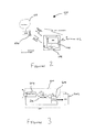
- a user equipment (UE) 102 would like to establish a communication link to a macro-cell base station 104.
- the macro cell base station 104 is in communication with an access network 105.
- the macro cell provides for a wider coverage range, but only a limited capacity, mainly due to the larger number of connected UEs and the larger separation distances from its UEs.
- the network also contains an ESSC 106 whose default mode is sleep.
- the ESSC 106 may be in sleep mode over 90% of time.
- the limited ESSC coverage is contained within the macro cell coverage. Given its closer physical proximity to the UE 102, the ESSC 106 can serve high-rate users.
- the ESSC 106 may be powered by energy scavenging, such as solar, wind energy and/or battery.
- the ESSC 106 may be asleep most of the time and may be connected to an ultra low powered transceiver (ULPT) 108.
- This ULPT 108 is always turned on to sense the overall network, and listen for wake-up signals/beacon signals/control signals from either the UE 102 or the macro cell base station 104. Note that the ULPT 108 only listens to the signals from the base station and operates at a fraction of the overall power.
- the ULPT 108 is responsible for turning the ESSC 106 on when required by the macro cell base station 104 or UE 120 to enable high-data rate communication of the UE 102 and the macro cell base station 104.
- the ULPT 108 operates to actively control the wake-up/sleep modes of an ESSC, it is operable to dynamically control the configuration of the ESSC.
- the ULPT 108 acts as a physical interface to the ESSC 106 that can be accessed by both the UE 102 and macro cell base station 104.
- the ULPT 108 minimizes the overall ESSC energy consumption.
- the proposed cross-layered communication architectures effectively control the ESSC by defining ULPT architecture and signaling techniques to dynamically control ESSCs.
- control' here refers to dynamic reconfiguration of ESSC parameters such as power amplifier levels, frequency of operation, beamforming/spatial multiplexing, etc., as well as to wake-up and shut down of the ESSC.
- the ULPT 108 has ultra-low power consumption while it senses for signals from the UE 102 and/or the access network 105.
- the components of ULPT 108 may be limited to energy detectors, passive circuits (RF filters) and a low-power microcontroller with power consumption in the order of milliwatts and can be powered by a small solar panel.
- the signal processing capabilities of the ULPT 108 may be restricted to detecting a limited set of waveforms/messages at a very low rate.
- the network connections between the proposed ESSC106 and ULPT 108, the access network 105 and the UE 102 are shown in Figure 2 .
- the overlay macro cell transmits the primary synchronization signal (PSS), secondary synchronization signal (SSS), CRS and broadcast channel (BCH) whereby the ESSC 106 also remains in sleep state unless specified by the access network 105 or the UE 102.
- PSS primary synchronization signal
- SSS secondary synchronization signal
- BCH broadcast channel
- both the UE and the macro cell can wake up the ESSC, although a technically preferred option to let the macro cell perform this task given its knowledge of the local networking conditions.
- a ULPT 108 is used as will be described in more detail in relation to Figure 3 .
- FIG. 3 schematically shows an ultra-low power transceiver (ULPT) 200 and an ESSC 202.
- ULPT 200 comprises an energy detector 204, network node identification unit 206 and a microcontroller 208 to manage the control plane operations.
- Each block of the ULPT 200 is used to enable or turn on the subsequent block to achieve power savings.
- the energy detector 204 may be used to detect the control signals from either the UE or the access network/backhaul. Note that the access network and UE might communicate in two different frequencies, for this reason the energy detector block may consist of two or more energy detectors and filters depending on their frequencies and bandwidth of operation.
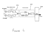
- Figure 4 shows the general schematic of one such energy detector in which two energy detectors are provided and in which the ESSC antenna signals are amplified, band-pass filtered, and subsampled at a frequency.
- energy detector 204 If energy detector 204 output signal energy exceeds a particular threshold, the remaining ULPT circuitry is enabled.
- energy detector 204 may be any suitable detector operable to identify signals from UEs and the access network. Note that the energy detector can be designed using only a few transceivers and thus results in very low power consumption. The energy detector 204 identifies any signal exceeding a particular threshold, but it does not provide any information on their properties. For example, it cannot distinguish whether a detected signal sequence corresponds to the identity of the ESSC network node. Therefore, the ULPT also comprises a network node determination unit 206. In the embodiment shown in Figure 3 , the network node determination unit 206 is a pilot decorrelator block 206 operable to estimate whether the energy detector output corresponds to the ESSC cell identity.
- pilot decorrelator may be any suitable determination unit operable to estimate whether the energy detector output corresponds to the ESSC cell identity.
- Each ESSC can be identified using either a reference signal, such as Chu-Zadoff polyphase code sequence in LTE or a CDMA signature sequence such as a Gold code.
- a reference signal such as Chu-Zadoff polyphase code sequence in LTE
- CDMA signature sequence such as a Gold code.
- Such families of code sequences rely on good auto-correlation and poor cross-correlation properties.
- the pilot decorrelator 206 inside the ULPT 200 may compute the auto-correlation, using delayed replicas of received sequence. If this exceeds a specific threshold, the microcontroller 208 is enabled.
- the ESSC 202 may be an RF repeater incapable of determining if signals originate from either the access network or the UE. However, the ESSC 202 should wake-up/shut down in presence of UEs and/or upon the request of a macro cell. Furthermore, it should also allow for adaptive/dynamic control.
- the microcontroller 208 therefore decodes the output of correlation detector 206 and depending on the decoded signal, communicates with different components of the ESSC 202 to modify their operations and hence control of the overall ESSC 202 operation.
- the ULPT control signals can concern multiple features of the ESSC functionality such as, but not limited to power amplifier output power levels, dynamic spectrum allocation and antenna pattern selection and beamforming.
- the access network may estimate the required power levels that the power amplifier of the ESSC must transmit with, in order to maximize the network capacity. These signals can be relayed to ULPT microcontroller 208 to modify the power output power levels of the ESSC 202 using a digitally controlled attenuator.
- the access network may estimate white spaces in the overall spectrum, similar to cognitive radio, and may relays the specific values to the ULPT 200.
- the ULPT 200 may modify the PLL frequencies of the RF mixer of the ESSC 202, responsive to the values relayed from the access network.
- the coverage and signal to noise ratio (SNR) between ESSC 202 and its UEs can be enhanced using multiple antennas and analog/RF beamforming.
- the access network based on estimates of ESSC position and its UEs positions, may calculate the beamformer weights to maximize SINR between the ESSC 202 and its UEs, and conveys beamformer weights to the ESSC 202 via the ULPT 200.
- a low-power implementation of the ULPT 200 is shown in Figure 4 , where the delay, correlation and energy (summation) depends on the specific Gold code sequence. If that specific code sequence is received, the pilot decorrelator 206 transmits the corresponding message to the microcontroller 208.
- two energy detectors are provided in the energy detector block 204, to detect control signals from UEs and the access network at different frequency bands.
- the power consumption of the energy detector andnetwork node determination unit is in the order of tens of milliWatts and can be driven using a 25 cm 2 solar panel.
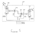
- Figure 5 schematically shows Dynamic control from the ULPT microcontroller (not shown) to the ESSC 300 to implement spectral, power and spatial resource allocation techniques.
- the ESSC 300 comprises a number of digitally controlled RF components such as power amplifiers/attenuators 302, PLLs 304, 306 and phase shifters 308, 310.
- the digital control from the ULPT microcontroller provides necessary flexibility/programmability to modulate radiated power over the spatial, spectral and temporal dimensions.
- the control flow from microcontroller to ESSC is shown in Figure 5 .
- the network can estimate unused spectral blocks for downlink as well as uplink communications between UE and ESSC 300. Note that enabling communications between a UE and ESSC 300 in these white-spaces will maximize the SINR between UE and ESSC. The same operation can be repeated to maximize the SINR between backhaul/access network and the ESSC. In this case, the network estimates the white-spaces in the backhaul spectrum.
- a baseband-RF upconverter such as the Analog Devices (RTM) ADF4350 used in current macro cell implementations.
- This mixer can be programmed using SPI interface to operate at a carrier frequency estimated by the network by writing inside the registers present in ADF4350.
- the network conveys the desired spectral allocations to the ULPT.
- the ULPT micro-controller programs the appropriate registers
- the network estimates the required power levels at the ESSC 300 in order to either maximize the network capacity or to minimize the interference to the neighboring cells. This is possible on the basis of UE UL signal strength. For example, consider a digitally controller power amplifier attenuator combination such as Peregrine Semiconductor Corp. (RTM) PE4302. Programming the desired power levels to these components through the ULPT microcontroller would result in energy efficient operation. An alternative approach to modify power levels is through output power levels in the ADF4350.
- RTM Peregrine Semiconductor Corp.
- the network can estimate desired beam patterns to either maximize the network capacity or to minimize the interference to the neighboring cells. Subsequently, the network provides these weights to the transceiver of each base station.
- Phase shifters 308, 310 comprise an array of RF digitally controlled phase shifters, such as Hittite Microwave Corp (RTM) MC928LP5E, each connected to a transmit antenna and beamform signals towards a specific user.
- RTM Hittite Microwave Corp
- the proposed sensing transceiver controls in energy-sustaining small cells (ESSCs) and reduces power consumption in ESSCs.
- the above described embodiments not only provide efficient wake-up of an ESSC, but also enable its configuration/re-configuration both upon ESSC wake-up and during subsequent operation.
- the above described embodiments also provide a centralized approach to dynamically control the physical operations of ESSCs in order to optimize performance (e.g., capacity enhancement via interference management) in the network.
- the main high-power communication chain of the ESSC is excluded from any overhead generated due to the reconfiguration of the ESSC which results in significant improvement of ESSC energy-efficiency at low costs.
- the wake-up/configuration actions are carried out by an ultra-low power transceiver able to recognize cell-identity specific commands and implement them in an energy-efficient manner without using any sort of energy-intensive and cost-ineffective digital processing.
- a low-complexity physical implementation is provided for future networks with split control/data plane and enabled sleep modes. Thus, it facilitates network deployment, mitigates radio-link and handover failures, and simplifies cell identification.
- each ESSC may be provided with an integral ULPT. Also, it should be appreciated that a single ULPT may be operable control a plurality of ESSCs.
Landscapes
- Engineering & Computer Science (AREA)
- Computer Networks & Wireless Communication (AREA)
- Signal Processing (AREA)
- Mobile Radio Communication Systems (AREA)
Abstract
Description
- The present invention relates to a transceiver for controlling a network node. In particular, but not exclusively, the present invention relates to an ultra-low power transceiver for controlling a energy-sustaining small cell base station.
- Small cells are low power, low-cost base stations that are able to provide cellular service in residential or enterprise environments, with a typical coverage range of tens of metres. They have auto-configuration and self-optimization capabilities that enable a simple plug and play deployment, and are designed to automatically integrate themselves into an existing macrocellular network. Small cells, often referred to as, typically use the customer's broadband internet connection, for example DSL, cable or the like, as backhaul towards the macrocellular network.
- Adoption small cells by wireless operators is widespread and with the increasing rate of adoption, the ability to integrate deployed small cells into the existing macrocellular network as seamlessly as possible is becoming increasingly important.
- The numbers of small cells in densely populated areas can outnumber the hosting macro cells by a factor of 5 to 10 or more per macro cell sector. The installation cost and the power consumption associated with these small cells can be significant. Therefore, it is desirable to reduce the installation effort and power consumption of these small cells as much as possible. This can be achieved by minimizing backhaul installation by using wireless backhaul, instead of cable/fibre based backhaul, and by reducing power supply installation, for example by using an autonomous source of locally sustainable energy (e.g., solar panels or energy harvesting devices) in combination with storage/back-up battery, instead of cable-connected external power supply.
- Small cell base stations operating on the basis of sustainable energy sources may sometimes referred to as energy-sustaining small cells (ESSCs). However, sources of sustainable energy typically do not allow for an uninterrupted duty cycle. Therefore, ESSCs are expected to be activated only on a need-to-communicate basis, e.g., when a nearby mobile device requests large throughput, or if a mobile terminal is located in an area served badly by the hosting macro cell. Generally speaking, ESSCs will remain in a sleep mode for most of their deployment time, while harvesting external energy (e.g., solar and wind energy) and storing it in a battery.
- It is therefore desirable to provide techniques that allow an ESSC to be activated in an energy efficient way. It is also desirable to provide techniques that as allow an ESSC to be adaptively configured/re-configured during subsequent ESSC operation. It is also desirable to provide techniques that allow reconfiguration to be efficiently implemented.
- According to a first aspect of the invention, there is provided a transceiver for controlling a first network node, comprising: a detector operable to detect a control signal from a second network node or a user equipment; a network node determination unit operable responsive to the detector to determine that the detected control signal relates to the first network node; and a controller operable responsive to the determination unit to control the first network node based on the detected control signal.
- The above first aspect enables the acts of waking-up and configuring/re-configuring a first network node in an energy-efficient manner that does not rely on any digital processing, by using sniffer-like circuitry in the first network node that dynamically controls the first network node without relying on the primary communication chain of the first network node.
- The first network node may be a small cell base station. The first network node may be an energy sustaining small cell base station. The second network node may be a macro cell base station or a user equipment. The detector may be an energy detector. The detector may be signal detection circuitry or energy detection circuitry. The determination unit may be a decorrelator. The determination unit may be a sequence estimator or user identification unit, such as a CDMA code embedded in a mobile phone. The controller may be a microcontroller.
- The determination unit may be enabled when the output of the detector changes by and/or exceeds a threshold value indicating that a control signal has been detected.
- The controller may be enabled when the determination unit determines that the control signal relates to the first network node.
- The controller may be operable to generate one or more digital control signals based on the detected control signal to control the first network node. The control signal may be decoded by the network node determination unit.
- The controller may be operable to generate a digital control signal to control the operation frequency of the output of the first network node based on the detected control signal. The controller may be operable to generate a digital control signal to control the termporal and code dimension output of the first network node.
- The controller may be operable to generate a digital control signal to control the power output of the first network based on the detected control signal. The controller may be operable to generate a digital control signal to modulate/vary the power of the signal transmitted from the first network node.
- The controller may be operable to generate a digital control signal to control the spatial orientation of the output of the first network node based on the detected control signal.
- The detector may comprise two or more detectors operable to detect control signals of different frequencies.
- The network node determination unit may be operable to determine that the control signal corresponds to the first network node using a polyphase code or Gold code. The network node determination unit may be operable to robustly identify and associate the control signal with the first network node. Such identification may achieved using a code sequences such as Gold codes (CDMA) or polyphase codes.
- The transceiver may be an ultra-low power transceiver and the first network node may be an energy-sustaining small cell base station. The first network node may be any network node operable in a sleep mode and an awake/active mode.
- According to a second aspect of the invention, there is provided a first network node operable to communication with a second network node, wherein the first network node is operable to be controlled by a transceiver according to the first aspect.
- The first network node may comprise a mixer, a power amplifier and phase-shift beamformers, and wherein the controller of the transceiver is operable to generate one or more digital control signals based on the detected control signal to control the mixer, power amplifier and phase-shift beamformers of the first network node so as to control the operation frequency, power output and spatial orientation of the first network node.
- According to a third aspect of the invention, there is provided a telecommunications system, comprising: a first network node; and a second network node, wherein the first network node is operable to communicate with a second network node, and the first network node comprises a transceiver for controlling the first network node according to the first aspect.
- According to a fourth aspect of the invention, there is provided a method of controlling a first network node with a transceiver comprising a detector, a network node determination unit and a controller, the method comprising: detecting a control signal from a second network node or a user equipment at the detector and determining that the output of the detector exceeds a threshold value, thereby indicating that a control signal has been detected; enabling the determination unit and determining that the detected control signal relates to the first network node; enabling the controller and generating one or more digital control signals based on the detected control signal; and controlling the first network node based on the generated digital control signals.
- According to a fifth aspect of the invention, there is provided a computer program product operable when executed on a computer to perform the method of the above first aspect.
- Further particular and preferred aspects of the invention are set out in the accompanying independent and dependent claims.
- Some embodiments of the apparatus and/or methods in accordance with embodiment of the present invention are now described, by way of example only, with reference to the accompanying drawings, in which:
-
Figure 1 schematically shows an example of a telecommunications network comprising a plurality of ESSCs and a macro cell; -
Figure 2 schematically shows network access of an ESSC using an ultra-low power transceiver and access network/backhaul -
Figure 3 schematically shows an ultra-low power transceiver and an ESSC; -
Figure 4 schematically shows an ultra-low power transceiver; and -
Figure 5 schematically shows ESSC control using an ultra-low power transceiver. -
Figure 1 illustrates aheterogeneous telecommunications network 10 comprising a macro cell with acoverage area 12 and a plurality of energy sustaining small cells (ESSCs). The ESSCs comprises afirst ESSC 14, asecond ESSC 16 and athird ESSC 18. The ESSCs are distributed geographically to provide an area of coverage within themacro cell 12. User equipment may roam through thenetwork 10. When the user equipment is located within themacro cell 12, communications may be established between the user equipment and the macrocell base station 20 over an associated radio link. If a user equipment is located geographically within one of theESSCs Figure 1 shows only an example heterogeneous network and that a plurality of macro cells may be provided, more or less than three ESSCs may be provided. - The ESSCs cells provide local communications coverage for a user in their vicinity. As a user equipment comes within range of an ESSC, such as the
first ESSC 14, a handover may occur between thebase station 20 of the macro cell and the base station of the first ESSC14, when the base station of the first ESSC detects that user equipment has come within range. Likewise, as a user equipment comes within range of a different small cell, a handover may occur between the base station of the current small cell and the base station of the new small cell, when the base station of the new small cell detects that user equipment has come within range. - Generally small cell base stations are externally powered and are therefore generally continually active and do not have a sleep mode of operation, or if a sleep mode is provided for, the sleep mode/wake-up control mechanisms are initiated through the network (backhaul) connections. This approach requires keeping open a channel from the small cell to the network controller, at least sporadically or periodically.
- However, ESSCs such as those shown in
Figure 1 , are small cell base stations operating on the basis of sustainable energy sources that are connected wirelessly to the network. As sustainable energy sources usually operate using energy harvesting, such sources of sustainable energy typically do not allow for an uninterrupted duty cycle. It is therefore desirable that ESSCs are kept in a sleep mode and are only activated on a need-to-communicate basis, e.g., when a nearby mobile device requests large throughput, or if a mobile terminal is located in an area served badly by the hosting macro cell. Generally speaking, ESSCs will remain in a sleep mode for most of their deployment time, while harvesting external energy (e.g., solar and wind energy) and storing it in a battery. Please note that standard components of heterogeneous small cell networks such as pico-cell routers and remote radio heads contain digital processing, FPGA, and control blocks, that are not present in ESSCs. - It is therefore desirable to provide techniques by which energy efficient activation of an ESSC may be performed, as well as adaptively configuring/re-configuring the ESSC (e.g., selection of ESSC frequency band, beam-forming) and enabling ESSC re-configurability during subsequent ESSC operation (e.g., power control).
- Consider the
heterogeneous network 100 as shown inFigure 2 , where a user equipment (UE) 102 would like to establish a communication link to amacro-cell base station 104. The macrocell base station 104 is in communication with anaccess network 105. Compared to a small cell, the macro cell provides for a wider coverage range, but only a limited capacity, mainly due to the larger number of connected UEs and the larger separation distances from its UEs. - The network also contains an
ESSC 106 whose default mode is sleep. TheESSC 106 may be in sleep mode over 90% of time. The limited ESSC coverage is contained within the macro cell coverage. Given its closer physical proximity to theUE 102, theESSC 106 can serve high-rate users. TheESSC 106 may be powered by energy scavenging, such as solar, wind energy and/or battery. - The
ESSC 106 may be asleep most of the time and may be connected to an ultra low powered transceiver (ULPT) 108. ThisULPT 108 is always turned on to sense the overall network, and listen for wake-up signals/beacon signals/control signals from either theUE 102 or the macrocell base station 104. Note that theULPT 108 only listens to the signals from the base station and operates at a fraction of the overall power. - The
ULPT 108 is responsible for turning theESSC 106 on when required by the macrocell base station 104 or UE 120 to enable high-data rate communication of theUE 102 and the macrocell base station 104. - Not only does the
ULPT 108 operate to actively control the wake-up/sleep modes of an ESSC, it is operable to dynamically control the configuration of the ESSC. In other words, theULPT 108 acts as a physical interface to theESSC 106 that can be accessed by both theUE 102 and macrocell base station 104. By offloading the functionality of the sleep control of theESSC 106 to theULPT 108, theULPT 108 minimizes the overall ESSC energy consumption. - In particular, as will be described below, the proposed cross-layered communication architectures effectively control the ESSC by defining ULPT architecture and signaling techniques to dynamically control ESSCs. It should be noted that the term 'control' here refers to dynamic reconfiguration of ESSC parameters such as power amplifier levels, frequency of operation, beamforming/spatial multiplexing, etc., as well as to wake-up and shut down of the ESSC.
- The
ULPT 108 has ultra-low power consumption while it senses for signals from theUE 102 and/or theaccess network 105. Thus, the components ofULPT 108 may be limited to energy detectors, passive circuits (RF filters) and a low-power microcontroller with power consumption in the order of milliwatts and can be powered by a small solar panel. The signal processing capabilities of theULPT 108 may be restricted to detecting a limited set of waveforms/messages at a very low rate. - The network connections between the proposed ESSC106 and
ULPT 108, theaccess network 105 and theUE 102 are shown inFigure 2 . The overlay macro cell transmits the primary synchronization signal (PSS), secondary synchronization signal (SSS), CRS and broadcast channel (BCH) whereby theESSC 106 also remains in sleep state unless specified by theaccess network 105 or theUE 102. - In general, both the UE and the macro cell can wake up the ESSC, although a technically preferred option to let the macro cell perform this task given its knowledge of the local networking conditions. To this end, a
ULPT 108 is used as will be described in more detail in relation toFigure 3 . -
Figure 3 schematically shows an ultra-low power transceiver (ULPT) 200 and anESSC 202.ULPT 200 comprises anenergy detector 204, networknode identification unit 206 and amicrocontroller 208 to manage the control plane operations. Each block of theULPT 200 is used to enable or turn on the subsequent block to achieve power savings. - The
energy detector 204 may be used to detect the control signals from either the UE or the access network/backhaul. Note that the access network and UE might communicate in two different frequencies, for this reason the energy detector block may consist of two or more energy detectors and filters depending on their frequencies and bandwidth of operation.Figure 4 shows the general schematic of one such energy detector in which two energy detectors are provided and in which the ESSC antenna signals are amplified, band-pass filtered, and subsampled at a frequency. - If
energy detector 204 output signal energy exceeds a particular threshold, the remaining ULPT circuitry is enabled. - It should be appreciated that
energy detector 204 may be any suitable detector operable to identify signals from UEs and the access network. Note that the energy detector can be designed using only a few transceivers and thus results in very low power consumption. Theenergy detector 204 identifies any signal exceeding a particular threshold, but it does not provide any information on their properties. For example, it cannot distinguish whether a detected signal sequence corresponds to the identity of the ESSC network node. Therefore, the ULPT also comprises a networknode determination unit 206. In the embodiment shown inFigure 3 , the networknode determination unit 206 is apilot decorrelator block 206 operable to estimate whether the energy detector output corresponds to the ESSC cell identity. This is achieved by estimating the energy of the pilot sequence, comparing with threshold energy levels and inputting this sequence tomicrocontroller 208. It should be appreciated that the pilot decorrelator may be any suitable determination unit operable to estimate whether the energy detector output corresponds to the ESSC cell identity. - Each ESSC can be identified using either a reference signal, such as Chu-Zadoff polyphase code sequence in LTE or a CDMA signature sequence such as a Gold code. Such families of code sequences rely on good auto-correlation and poor cross-correlation properties. The
pilot decorrelator 206 inside theULPT 200 may compute the auto-correlation, using delayed replicas of received sequence. If this exceeds a specific threshold, themicrocontroller 208 is enabled. - The
ESSC 202 may be an RF repeater incapable of determining if signals originate from either the access network or the UE. However, theESSC 202 should wake-up/shut down in presence of UEs and/or upon the request of a macro cell. Furthermore, it should also allow for adaptive/dynamic control. Themicrocontroller 208 therefore decodes the output ofcorrelation detector 206 and depending on the decoded signal, communicates with different components of theESSC 202 to modify their operations and hence control of theoverall ESSC 202 operation. - The ULPT control signals can concern multiple features of the ESSC functionality such as, but not limited to power amplifier output power levels, dynamic spectrum allocation and antenna pattern selection and beamforming.
- For example, the access network may estimate the required power levels that the power amplifier of the ESSC must transmit with, in order to maximize the network capacity. These signals can be relayed to
ULPT microcontroller 208 to modify the power output power levels of theESSC 202 using a digitally controlled attenuator. - Also, the access network may estimate white spaces in the overall spectrum, similar to cognitive radio, and may relays the specific values to the
ULPT 200. TheULPT 200 may modify the PLL frequencies of the RF mixer of theESSC 202, responsive to the values relayed from the access network. - Further, the coverage and signal to noise ratio (SNR) between
ESSC 202 and its UEs can be enhanced using multiple antennas and analog/RF beamforming. In this case, the access network based on estimates of ESSC position and its UEs positions, may calculate the beamformer weights to maximize SINR between theESSC 202 and its UEs, and conveys beamformer weights to theESSC 202 via theULPT 200. - A low-power implementation of the
ULPT 200 is shown inFigure 4 , where the delay, correlation and energy (summation) depends on the specific Gold code sequence. If that specific code sequence is received, thepilot decorrelator 206 transmits the corresponding message to themicrocontroller 208. - As can be seen in
Figure 4 , two energy detectors are provided in theenergy detector block 204, to detect control signals from UEs and the access network at different frequency bands. The power consumption of the energy detector andnetwork node determination unit is in the order of tens of milliWatts and can be driven using a 25 cm2 solar panel. -
Figure 5 schematically shows Dynamic control from the ULPT microcontroller (not shown) to theESSC 300 to implement spectral, power and spatial resource allocation techniques. - The
ESSC 300 comprises a number of digitally controlled RF components such as power amplifiers/attenuators 302,PLLs phase shifters Figure 5 . - Firstly, we consider dynamic spectrum
allocation using PLLs ESSC 300. Note that enabling communications between a UE andESSC 300 in these white-spaces will maximize the SINR between UE and ESSC. The same operation can be repeated to maximize the SINR between backhaul/access network and the ESSC. In this case, the network estimates the white-spaces in the backhaul spectrum. - For example, consider a baseband-RF upconverter, such as the Analog Devices (RTM) ADF4350 used in current macro cell implementations. This mixer can be programmed using SPI interface to operate at a carrier frequency estimated by the network by writing inside the registers present in ADF4350. The network conveys the desired spectral allocations to the ULPT. The ULPT micro-controller programs the appropriate registers
- Next let us consider
power amplifier 302 output power levels. The network estimates the required power levels at theESSC 300 in order to either maximize the network capacity or to minimize the interference to the neighboring cells. This is possible on the basis of UE UL signal strength. For example, consider a digitally controller power amplifier attenuator combination such as Peregrine Semiconductor Corp. (RTM) PE4302. Programming the desired power levels to these components through the ULPT microcontroller would result in energy efficient operation. An alternative approach to modify power levels is through output power levels in the ADF4350. - Now let us consider antenna pattern selection and beamforming. The network can estimate desired beam patterns to either maximize the network capacity or to minimize the interference to the neighboring cells. Subsequently, the network provides these weights to the transceiver of each base station.
- Beamforming can be achieved either using active transceivers or using passive components such as a phase shifter array. However, in
ESSC 300 the number of transceivers is only one and the beamforming is limited to RF beamforming.Phase shifters - The proposed sensing transceiver (ULPT) controls in energy-sustaining small cells (ESSCs) and reduces power consumption in ESSCs.
- The above described embodiments not only provide efficient wake-up of an ESSC, but also enable its configuration/re-configuration both upon ESSC wake-up and during subsequent operation. The above described embodiments also provide a centralized approach to dynamically control the physical operations of ESSCs in order to optimize performance (e.g., capacity enhancement via interference management) in the network.
- The above described embodiments provide at least the following advantages. Firstly the main high-power communication chain of the ESSC is excluded from any overhead generated due to the reconfiguration of the ESSC which results in significant improvement of ESSC energy-efficiency at low costs. Secondly, the wake-up/configuration actions are carried out by an ultra-low power transceiver able to recognize cell-identity specific commands and implement them in an energy-efficient manner without using any sort of energy-intensive and cost-ineffective digital processing. Thirdly a low-complexity physical implementation is provided for future networks with split control/data plane and enabled sleep modes. Thus, it facilitates network deployment, mitigates radio-link and handover failures, and simplifies cell identification.
- Although the above describes the ULPT being a separate entity to the ESSC, it should be appreciated that each ESSC may be provided with an integral ULPT. Also, it should be appreciated that a single ULPT may be operable control a plurality of ESSCs.
- The present inventions may be embodied in other specific apparatus and/or methods. The described embodiments are to be considered in all respects as only illustrative and not restrictive. In particular, the scope of the invention is indicated by the appended claims rather than by the description and figures herein. All changes that come within the meaning and range of equivalency of the claims are to be embraced within their scope.
Claims (15)
- A transceiver for controlling a first network node, comprising:a detector operable to detect a control signal from a second network node or a user equipment;a network node determination unit operable responsive to the detector to determine that the detected control signal relates to the first network node; anda controller operable responsive to the determination unit to control the first network node based on the detected control signal.
- A transceiver according to claim 1, wherein the determination unit is enabled when the output of the detector changes by and/or exceeds a threshold value indicating that a control signal has been detected.
- A transceiver according to claim 1 or 2, wherein the controller is enabled when the determination unit determines that the control signal relates to the first network node.
- A transceiver according to any preceding claim, wherein the controller is operable to generate one or more digital control signals based on the detected control signal to control the first network node.
- A transceiver according to claim 4, wherein the controller is operable to generate a digital control signal to control the operation frequency of the output of the first network node based on the detected control signal.
- A transceiver according to claim 4 or 5, wherein the controller is operable to generate a digital control signal to control the power output of the first network based on the detected control signal.
- A transceiver according to claim 4, 5 or 6, wherein the controller is operable to generate a digital control signal to control the spatial orientation of the output of the first network node based on the detected control signal.
- A transceiver according to any preceding claim, wherein the detector comprises two or more detectors operable to detect control signals of different frequencies.
- A transceiver according to any preceding claim, wherein the network node determination unit is operable to determine that the control signal corresponds to the first network node using a polyphase code or Gold code.
- A transceiver according to any preceding claim, wherein the transceiver is an ultra-low power transceiver and the first network node is an energy-sustaining small cell base station.
- A first network node operable to communication with a second network node, wherein the first network node is operable to be controlled by a transceiver according to any preceding claim.
- A first network node according to claim 11, comprising a mixer, a power amplifier and phase-shift beamformers, and wherein the controller of the transceiver is operable to generate one or more digital control signals based on the detected control signal to control the mixer, power amplifier and phase-shift beamformers of the first network node so as to control the operation frequency, power output and spatial orientation of the first network node.
- A telecommunications system, comprising:a first network node; anda second network node, wherein the first network node is operable to communicate with a second network node, and the first network node comprises a transceiver for controlling the first network node according to any of claims 1 to 10.
- A method of controlling a first network node with a transceiver comprising a detector, a network node determination unit and a controller, the method comprising:detecting a control signal from a second network node or a user equipment at the detector and determining that the output of the detector exceeds a threshold value, thereby indicating that a control signal has been detected;enabling the determination unit and determining that the detected control signal relates to the first network node;enabling the controller and generating one or more digital control signals based on the detected control signal; andcontrolling the first network node based on the generated digital control signals.
- A computer program product operable when executed on a computer to perform the method of claim 14.
Priority Applications (1)
| Application Number | Priority Date | Filing Date | Title |
|---|---|---|---|
| EP13290192.7A EP2838294B1 (en) | 2013-08-16 | 2013-08-16 | A transceiver, a network node, telecommunications system and communication method |
Applications Claiming Priority (1)
| Application Number | Priority Date | Filing Date | Title |
|---|---|---|---|
| EP13290192.7A EP2838294B1 (en) | 2013-08-16 | 2013-08-16 | A transceiver, a network node, telecommunications system and communication method |
Publications (2)
| Publication Number | Publication Date |
|---|---|
| EP2838294A1 true EP2838294A1 (en) | 2015-02-18 |
| EP2838294B1 EP2838294B1 (en) | 2020-03-18 |
Family
ID=49303913
Family Applications (1)
| Application Number | Title | Priority Date | Filing Date |
|---|---|---|---|
| EP13290192.7A Active EP2838294B1 (en) | 2013-08-16 | 2013-08-16 | A transceiver, a network node, telecommunications system and communication method |
Country Status (1)
| Country | Link |
|---|---|
| EP (1) | EP2838294B1 (en) |
Cited By (5)
| Publication number | Priority date | Publication date | Assignee | Title |
|---|---|---|---|---|
| WO2018183338A1 (en) * | 2017-03-31 | 2018-10-04 | A9.Com, Inc. | Wireless security network and communication methods |
| US10115278B2 (en) | 2017-03-31 | 2018-10-30 | A9.Com, Inc. | Wireless security network and communication methods |
| US10235852B2 (en) | 2016-08-29 | 2019-03-19 | A9.Com, Inc. | Wireless security network and communication methods |
| US10624086B2 (en) | 2017-03-31 | 2020-04-14 | A9.Com, Inc. | Wireless security network and communication methods |
| EP4020853A1 (en) * | 2020-12-24 | 2022-06-29 | INTEL Corporation | A distributed radiohead system |
Citations (4)
| Publication number | Priority date | Publication date | Assignee | Title |
|---|---|---|---|---|
| US20100056184A1 (en) * | 2008-08-26 | 2010-03-04 | Motorola, Inc. | Presence-aware cellular communication system and method |
| EP2453706A1 (en) * | 2010-11-16 | 2012-05-16 | Alcatel Lucent | A small cell base station for wirless telecommuncations, and a method of switching between states |
| WO2012114969A1 (en) * | 2011-02-23 | 2012-08-30 | 株式会社国際電気通信基礎技術研究所 | Terminal device, wireless base station wirelessly communicating with same, and wireless communication system using terminal device and wireless base station |
| US20130189932A1 (en) * | 2010-09-28 | 2013-07-25 | Alcatel Lucent | Base station, user equipment and method of reducing energy consumption in a base station |
-
2013
- 2013-08-16 EP EP13290192.7A patent/EP2838294B1/en active Active
Patent Citations (5)
| Publication number | Priority date | Publication date | Assignee | Title |
|---|---|---|---|---|
| US20100056184A1 (en) * | 2008-08-26 | 2010-03-04 | Motorola, Inc. | Presence-aware cellular communication system and method |
| US20130189932A1 (en) * | 2010-09-28 | 2013-07-25 | Alcatel Lucent | Base station, user equipment and method of reducing energy consumption in a base station |
| EP2453706A1 (en) * | 2010-11-16 | 2012-05-16 | Alcatel Lucent | A small cell base station for wirless telecommuncations, and a method of switching between states |
| WO2012114969A1 (en) * | 2011-02-23 | 2012-08-30 | 株式会社国際電気通信基礎技術研究所 | Terminal device, wireless base station wirelessly communicating with same, and wireless communication system using terminal device and wireless base station |
| US20130329621A1 (en) * | 2011-02-23 | 2013-12-12 | Nec Communications Systems, Ltd. | Terminal device, wireless base station wirelessly communicating with the same, and wireless communication system using terminal device and wireless base station |
Non-Patent Citations (2)
| Title |
|---|
| ASHRAF I ET AL: "Power savings in small cell deployments via sleep mode techniques", 2010 IEEE 21ST INTERNATIONAL SYMPOSIUM ON PERSONAL, INDOOR AND MOBILE RADIO COMMUNICATIONS WORKSHOPS (PIMRC WORKSHOPS); 26-30 SEPT. 2010; INSTANBUL, TURKEY, IEEE, PISCATAWAY, NJ, USA, 26 September 2010 (2010-09-26), pages 307 - 311, XP031837067, ISBN: 978-1-4244-9117-9 * |
| IMRAN ASHRAF ET AL: "Improving Energy Efficiency of Femtocell Base Stations Via User Activity Detection", WIRELESS COMMUNICATIONS AND NETWORKING CONFERENCE (WCNC), 2010 IEEE, IEEE, PISCATAWAY, NJ, USA, 18 April 2010 (2010-04-18), pages 1 - 5, XP031706720, ISBN: 978-1-4244-6396-1 * |
Cited By (6)
| Publication number | Priority date | Publication date | Assignee | Title |
|---|---|---|---|---|
| US10235852B2 (en) | 2016-08-29 | 2019-03-19 | A9.Com, Inc. | Wireless security network and communication methods |
| WO2018183338A1 (en) * | 2017-03-31 | 2018-10-04 | A9.Com, Inc. | Wireless security network and communication methods |
| US10115278B2 (en) | 2017-03-31 | 2018-10-30 | A9.Com, Inc. | Wireless security network and communication methods |
| US10624086B2 (en) | 2017-03-31 | 2020-04-14 | A9.Com, Inc. | Wireless security network and communication methods |
| EP4020853A1 (en) * | 2020-12-24 | 2022-06-29 | INTEL Corporation | A distributed radiohead system |
| US12041540B2 (en) | 2020-12-24 | 2024-07-16 | Intel Corporation | Distributed radiohead system |
Also Published As
| Publication number | Publication date |
|---|---|
| EP2838294B1 (en) | 2020-03-18 |
Similar Documents
| Publication | Publication Date | Title |
|---|---|---|
| US20200187115A1 (en) | Method and Access Node for Supporting UE as Well as a UE and Corresponding Method Carried Out by the UE in a Wireless Communication System | |
| US9282510B2 (en) | Dynamic reorganization of cell structures in wireless networks | |
| KR20220103939A (en) | Synchronization signal block (SSB) measurement based on measurement cycle frequency | |
| US20160105853A1 (en) | Microcell power control method and base station | |
| EP2838294B1 (en) | A transceiver, a network node, telecommunications system and communication method | |
| US9220102B2 (en) | Low power base station and communication control method | |
| US20180192366A1 (en) | Inter-cell power coordination for energy efficient cellular network | |
| KR101217966B1 (en) | Synchronization between uncoordinated time division duplex communication networks | |
| Kalamkar et al. | Interference-aided energy harvesting: Cognitive relaying with multiple primary transceivers | |
| US9763106B2 (en) | Methods and devices for cell reconfiguration | |
| US9351243B2 (en) | Method and arrangement for a terminal of a wireless communication network | |
| EP2273827A1 (en) | Interference mitigation and avoidance whitin femtocells | |
| CN112313986A (en) | Method, apparatus and computer readable medium for RRM measurement | |
| US9603101B2 (en) | Technique for operating a network node in a heterogeneously deployed network | |
| EP2453706A1 (en) | A small cell base station for wirless telecommuncations, and a method of switching between states | |
| WO2022240686A1 (en) | Discovery resource selection based on rsrp value of a uu link | |
| JP4977239B2 (en) | Wireless communication device | |
| Wu et al. | Dynamic small cell on/off control for green ultra-dense networks | |
| US12581422B2 (en) | Unequal additional maximum power reduction for dual transmit modes | |
| US12335875B2 (en) | Coverage adaptation and impact on idle user equipment (UE) | |
| KR101610050B1 (en) | System of D2D communication based power control and Method for power control using the same | |
| US9521580B1 (en) | Reduction of interference potential between a cell tower and an electromagnetic radiation source | |
| Dudnikova et al. | A fully distributed algorithm for pilot power control in LTE femtocell networks | |
| JP2016092711A (en) | Base station and antenna control method | |
| WO2025257598A1 (en) | Distributed multiple input multiple output (mimo) location based power saving |
Legal Events
| Date | Code | Title | Description |
|---|---|---|---|
| 17P | Request for examination filed |
Effective date: 20130816 |
|
| AK | Designated contracting states |
Kind code of ref document: A1 Designated state(s): AL AT BE BG CH CY CZ DE DK EE ES FI FR GB GR HR HU IE IS IT LI LT LU LV MC MK MT NL NO PL PT RO RS SE SI SK SM TR |
|
| AX | Request for extension of the european patent |
Extension state: BA ME |
|
| PUAI | Public reference made under article 153(3) epc to a published international application that has entered the european phase |
Free format text: ORIGINAL CODE: 0009012 |
|
| R17P | Request for examination filed (corrected) |
Effective date: 20150818 |
|
| RBV | Designated contracting states (corrected) |
Designated state(s): AL AT BE BG CH CY CZ DE DK EE ES FI FR GB GR HR HU IE IS IT LI LT LU LV MC MK MT NL NO PL PT RO RS SE SI SK SM TR |
|
| STAA | Information on the status of an ep patent application or granted ep patent |
Free format text: STATUS: EXAMINATION IS IN PROGRESS |
|
| 17Q | First examination report despatched |
Effective date: 20170621 |
|
| RAP1 | Party data changed (applicant data changed or rights of an application transferred) |
Owner name: ALCATEL LUCENT |
|
| GRAP | Despatch of communication of intention to grant a patent |
Free format text: ORIGINAL CODE: EPIDOSNIGR1 |
|
| STAA | Information on the status of an ep patent application or granted ep patent |
Free format text: STATUS: GRANT OF PATENT IS INTENDED |
|
| INTG | Intention to grant announced |
Effective date: 20191002 |
|
| GRAS | Grant fee paid |
Free format text: ORIGINAL CODE: EPIDOSNIGR3 |
|
| GRAA | (expected) grant |
Free format text: ORIGINAL CODE: 0009210 |
|
| STAA | Information on the status of an ep patent application or granted ep patent |
Free format text: STATUS: THE PATENT HAS BEEN GRANTED |
|
| AK | Designated contracting states |
Kind code of ref document: B1 Designated state(s): AL AT BE BG CH CY CZ DE DK EE ES FI FR GB GR HR HU IE IS IT LI LT LU LV MC MK MT NL NO PL PT RO RS SE SI SK SM TR |
|
| REG | Reference to a national code |
Ref country code: GB Ref legal event code: FG4D |
|
| REG | Reference to a national code |
Ref country code: DE Ref legal event code: R096 Ref document number: 602013066912 Country of ref document: DE |
|
| REG | Reference to a national code |
Ref country code: AT Ref legal event code: REF Ref document number: 1247359 Country of ref document: AT Kind code of ref document: T Effective date: 20200415 Ref country code: IE Ref legal event code: FG4D |
|
| PG25 | Lapsed in a contracting state [announced via postgrant information from national office to epo] |
Ref country code: FI Free format text: LAPSE BECAUSE OF FAILURE TO SUBMIT A TRANSLATION OF THE DESCRIPTION OR TO PAY THE FEE WITHIN THE PRESCRIBED TIME-LIMIT Effective date: 20200318 Ref country code: NO Free format text: LAPSE BECAUSE OF FAILURE TO SUBMIT A TRANSLATION OF THE DESCRIPTION OR TO PAY THE FEE WITHIN THE PRESCRIBED TIME-LIMIT Effective date: 20200618 Ref country code: RS Free format text: LAPSE BECAUSE OF FAILURE TO SUBMIT A TRANSLATION OF THE DESCRIPTION OR TO PAY THE FEE WITHIN THE PRESCRIBED TIME-LIMIT Effective date: 20200318 |
|
| REG | Reference to a national code |
Ref country code: NL Ref legal event code: MP Effective date: 20200318 |
|
| PG25 | Lapsed in a contracting state [announced via postgrant information from national office to epo] |
Ref country code: BG Free format text: LAPSE BECAUSE OF FAILURE TO SUBMIT A TRANSLATION OF THE DESCRIPTION OR TO PAY THE FEE WITHIN THE PRESCRIBED TIME-LIMIT Effective date: 20200618 Ref country code: GR Free format text: LAPSE BECAUSE OF FAILURE TO SUBMIT A TRANSLATION OF THE DESCRIPTION OR TO PAY THE FEE WITHIN THE PRESCRIBED TIME-LIMIT Effective date: 20200619 Ref country code: SE Free format text: LAPSE BECAUSE OF FAILURE TO SUBMIT A TRANSLATION OF THE DESCRIPTION OR TO PAY THE FEE WITHIN THE PRESCRIBED TIME-LIMIT Effective date: 20200318 Ref country code: LV Free format text: LAPSE BECAUSE OF FAILURE TO SUBMIT A TRANSLATION OF THE DESCRIPTION OR TO PAY THE FEE WITHIN THE PRESCRIBED TIME-LIMIT Effective date: 20200318 Ref country code: HR Free format text: LAPSE BECAUSE OF FAILURE TO SUBMIT A TRANSLATION OF THE DESCRIPTION OR TO PAY THE FEE WITHIN THE PRESCRIBED TIME-LIMIT Effective date: 20200318 |
|
| REG | Reference to a national code |
Ref country code: LT Ref legal event code: MG4D |
|
| PG25 | Lapsed in a contracting state [announced via postgrant information from national office to epo] |
Ref country code: NL Free format text: LAPSE BECAUSE OF FAILURE TO SUBMIT A TRANSLATION OF THE DESCRIPTION OR TO PAY THE FEE WITHIN THE PRESCRIBED TIME-LIMIT Effective date: 20200318 |
|
| PG25 | Lapsed in a contracting state [announced via postgrant information from national office to epo] |
Ref country code: LT Free format text: LAPSE BECAUSE OF FAILURE TO SUBMIT A TRANSLATION OF THE DESCRIPTION OR TO PAY THE FEE WITHIN THE PRESCRIBED TIME-LIMIT Effective date: 20200318 Ref country code: RO Free format text: LAPSE BECAUSE OF FAILURE TO SUBMIT A TRANSLATION OF THE DESCRIPTION OR TO PAY THE FEE WITHIN THE PRESCRIBED TIME-LIMIT Effective date: 20200318 Ref country code: SK Free format text: LAPSE BECAUSE OF FAILURE TO SUBMIT A TRANSLATION OF THE DESCRIPTION OR TO PAY THE FEE WITHIN THE PRESCRIBED TIME-LIMIT Effective date: 20200318 Ref country code: IS Free format text: LAPSE BECAUSE OF FAILURE TO SUBMIT A TRANSLATION OF THE DESCRIPTION OR TO PAY THE FEE WITHIN THE PRESCRIBED TIME-LIMIT Effective date: 20200718 Ref country code: CZ Free format text: LAPSE BECAUSE OF FAILURE TO SUBMIT A TRANSLATION OF THE DESCRIPTION OR TO PAY THE FEE WITHIN THE PRESCRIBED TIME-LIMIT Effective date: 20200318 Ref country code: SM Free format text: LAPSE BECAUSE OF FAILURE TO SUBMIT A TRANSLATION OF THE DESCRIPTION OR TO PAY THE FEE WITHIN THE PRESCRIBED TIME-LIMIT Effective date: 20200318 Ref country code: PT Free format text: LAPSE BECAUSE OF FAILURE TO SUBMIT A TRANSLATION OF THE DESCRIPTION OR TO PAY THE FEE WITHIN THE PRESCRIBED TIME-LIMIT Effective date: 20200812 Ref country code: EE Free format text: LAPSE BECAUSE OF FAILURE TO SUBMIT A TRANSLATION OF THE DESCRIPTION OR TO PAY THE FEE WITHIN THE PRESCRIBED TIME-LIMIT Effective date: 20200318 |
|
| REG | Reference to a national code |
Ref country code: AT Ref legal event code: MK05 Ref document number: 1247359 Country of ref document: AT Kind code of ref document: T Effective date: 20200318 |
|
| REG | Reference to a national code |
Ref country code: DE Ref legal event code: R097 Ref document number: 602013066912 Country of ref document: DE |
|
| PLBE | No opposition filed within time limit |
Free format text: ORIGINAL CODE: 0009261 |
|
| STAA | Information on the status of an ep patent application or granted ep patent |
Free format text: STATUS: NO OPPOSITION FILED WITHIN TIME LIMIT |
|
| PG25 | Lapsed in a contracting state [announced via postgrant information from national office to epo] |
Ref country code: IT Free format text: LAPSE BECAUSE OF FAILURE TO SUBMIT A TRANSLATION OF THE DESCRIPTION OR TO PAY THE FEE WITHIN THE PRESCRIBED TIME-LIMIT Effective date: 20200318 Ref country code: AT Free format text: LAPSE BECAUSE OF FAILURE TO SUBMIT A TRANSLATION OF THE DESCRIPTION OR TO PAY THE FEE WITHIN THE PRESCRIBED TIME-LIMIT Effective date: 20200318 Ref country code: ES Free format text: LAPSE BECAUSE OF FAILURE TO SUBMIT A TRANSLATION OF THE DESCRIPTION OR TO PAY THE FEE WITHIN THE PRESCRIBED TIME-LIMIT Effective date: 20200318 Ref country code: DK Free format text: LAPSE BECAUSE OF FAILURE TO SUBMIT A TRANSLATION OF THE DESCRIPTION OR TO PAY THE FEE WITHIN THE PRESCRIBED TIME-LIMIT Effective date: 20200318 |
|
| 26N | No opposition filed |
Effective date: 20201221 |
|
| PG25 | Lapsed in a contracting state [announced via postgrant information from national office to epo] |
Ref country code: PL Free format text: LAPSE BECAUSE OF FAILURE TO SUBMIT A TRANSLATION OF THE DESCRIPTION OR TO PAY THE FEE WITHIN THE PRESCRIBED TIME-LIMIT Effective date: 20200318 |
|
| PG25 | Lapsed in a contracting state [announced via postgrant information from national office to epo] |
Ref country code: MC Free format text: LAPSE BECAUSE OF FAILURE TO SUBMIT A TRANSLATION OF THE DESCRIPTION OR TO PAY THE FEE WITHIN THE PRESCRIBED TIME-LIMIT Effective date: 20200318 |
|
| REG | Reference to a national code |
Ref country code: CH Ref legal event code: PL |
|
| PG25 | Lapsed in a contracting state [announced via postgrant information from national office to epo] |
Ref country code: LU Free format text: LAPSE BECAUSE OF NON-PAYMENT OF DUE FEES Effective date: 20200816 Ref country code: LI Free format text: LAPSE BECAUSE OF NON-PAYMENT OF DUE FEES Effective date: 20200831 Ref country code: CH Free format text: LAPSE BECAUSE OF NON-PAYMENT OF DUE FEES Effective date: 20200831 |
|
| REG | Reference to a national code |
Ref country code: BE Ref legal event code: MM Effective date: 20200831 |
|
| PG25 | Lapsed in a contracting state [announced via postgrant information from national office to epo] |
Ref country code: SI Free format text: LAPSE BECAUSE OF FAILURE TO SUBMIT A TRANSLATION OF THE DESCRIPTION OR TO PAY THE FEE WITHIN THE PRESCRIBED TIME-LIMIT Effective date: 20200318 |
|
| PG25 | Lapsed in a contracting state [announced via postgrant information from national office to epo] |
Ref country code: IE Free format text: LAPSE BECAUSE OF NON-PAYMENT OF DUE FEES Effective date: 20200816 Ref country code: BE Free format text: LAPSE BECAUSE OF NON-PAYMENT OF DUE FEES Effective date: 20200831 |
|
| PGFP | Annual fee paid to national office [announced via postgrant information from national office to epo] |
Ref country code: FR Payment date: 20210714 Year of fee payment: 9 |
|
| PG25 | Lapsed in a contracting state [announced via postgrant information from national office to epo] |
Ref country code: TR Free format text: LAPSE BECAUSE OF FAILURE TO SUBMIT A TRANSLATION OF THE DESCRIPTION OR TO PAY THE FEE WITHIN THE PRESCRIBED TIME-LIMIT Effective date: 20200318 Ref country code: MT Free format text: LAPSE BECAUSE OF FAILURE TO SUBMIT A TRANSLATION OF THE DESCRIPTION OR TO PAY THE FEE WITHIN THE PRESCRIBED TIME-LIMIT Effective date: 20200318 Ref country code: CY Free format text: LAPSE BECAUSE OF FAILURE TO SUBMIT A TRANSLATION OF THE DESCRIPTION OR TO PAY THE FEE WITHIN THE PRESCRIBED TIME-LIMIT Effective date: 20200318 |
|
| PG25 | Lapsed in a contracting state [announced via postgrant information from national office to epo] |
Ref country code: MK Free format text: LAPSE BECAUSE OF FAILURE TO SUBMIT A TRANSLATION OF THE DESCRIPTION OR TO PAY THE FEE WITHIN THE PRESCRIBED TIME-LIMIT Effective date: 20200318 Ref country code: AL Free format text: LAPSE BECAUSE OF FAILURE TO SUBMIT A TRANSLATION OF THE DESCRIPTION OR TO PAY THE FEE WITHIN THE PRESCRIBED TIME-LIMIT Effective date: 20200318 |
|
| PG25 | Lapsed in a contracting state [announced via postgrant information from national office to epo] |
Ref country code: FR Free format text: LAPSE BECAUSE OF NON-PAYMENT OF DUE FEES Effective date: 20220831 |
|
| PGFP | Annual fee paid to national office [announced via postgrant information from national office to epo] |
Ref country code: DE Payment date: 20250702 Year of fee payment: 13 |
|
| PGFP | Annual fee paid to national office [announced via postgrant information from national office to epo] |
Ref country code: GB Payment date: 20250703 Year of fee payment: 13 |