EP2838257A1 - A method for generating an immersive video of a plurality of persons - Google Patents
A method for generating an immersive video of a plurality of persons Download PDFInfo
- Publication number
- EP2838257A1 EP2838257A1 EP13306152.3A EP13306152A EP2838257A1 EP 2838257 A1 EP2838257 A1 EP 2838257A1 EP 13306152 A EP13306152 A EP 13306152A EP 2838257 A1 EP2838257 A1 EP 2838257A1
- Authority
- EP
- European Patent Office
- Prior art keywords
- client
- video
- video stream
- mixing
- routing
- Prior art date
- Legal status (The legal status is an assumption and is not a legal conclusion. Google has not performed a legal analysis and makes no representation as to the accuracy of the status listed.)
- Granted
Links
- 238000000034 method Methods 0.000 title claims abstract description 25
- 230000007175 bidirectional communication Effects 0.000 claims abstract description 20
- 230000006854 communication Effects 0.000 claims description 36
- 238000004891 communication Methods 0.000 claims description 36
- 239000000284 extract Substances 0.000 claims description 3
- 238000005516 engineering process Methods 0.000 description 7
- 238000004458 analytical method Methods 0.000 description 4
- 230000002457 bidirectional effect Effects 0.000 description 2
- 238000004590 computer program Methods 0.000 description 2
- 238000010586 diagram Methods 0.000 description 2
- 230000000694 effects Effects 0.000 description 2
- 230000005540 biological transmission Effects 0.000 description 1
- 230000021615 conjugation Effects 0.000 description 1
- 238000010276 construction Methods 0.000 description 1
- 238000001514 detection method Methods 0.000 description 1
- 238000012986 modification Methods 0.000 description 1
- 230000004048 modification Effects 0.000 description 1
- 230000000007 visual effect Effects 0.000 description 1
Images


Classifications
-
- H—ELECTRICITY
- H04—ELECTRIC COMMUNICATION TECHNIQUE
- H04N—PICTORIAL COMMUNICATION, e.g. TELEVISION
- H04N7/00—Television systems
- H04N7/14—Systems for two-way working
- H04N7/15—Conference systems
- H04N7/152—Multipoint control units therefor
-
- H—ELECTRICITY
- H04—ELECTRIC COMMUNICATION TECHNIQUE
- H04L—TRANSMISSION OF DIGITAL INFORMATION, e.g. TELEGRAPHIC COMMUNICATION
- H04L12/00—Data switching networks
- H04L12/02—Details
- H04L12/16—Arrangements for providing special services to substations
- H04L12/18—Arrangements for providing special services to substations for broadcast or conference, e.g. multicast
- H04L12/1813—Arrangements for providing special services to substations for broadcast or conference, e.g. multicast for computer conferences, e.g. chat rooms
- H04L12/1822—Conducting the conference, e.g. admission, detection, selection or grouping of participants, correlating users to one or more conference sessions, prioritising transmission
-
- H—ELECTRICITY
- H04—ELECTRIC COMMUNICATION TECHNIQUE
- H04N—PICTORIAL COMMUNICATION, e.g. TELEVISION
- H04N7/00—Television systems
- H04N7/08—Systems for the simultaneous or sequential transmission of more than one television signal, e.g. additional information signals, the signals occupying wholly or partially the same frequency band, e.g. by time division
- H04N7/0806—Systems for the simultaneous or sequential transmission of more than one television signal, e.g. additional information signals, the signals occupying wholly or partially the same frequency band, e.g. by time division the signals being two or more video signals
Definitions
- the invention relates to a method of video processing in a multi-participant video-conferencing system.
- Videoconferencing technologies use video and audio communication to allow a plurality of people to communicate at a same time, for instance for meeting activities. Furthermore, besides the audio and visual transmission of meeting activities, videoconferencing technologies can be used to share documents and display information.
- Each participant in a videoconference is filmed by a camera which generates a video stream representing the participant in his/her own environment.
- a camera which generates a video stream representing the participant in his/her own environment.
- two different technologies are generally used.
- a Video mixing based conference all incoming video streams from N participants are combined by a Multiparty Conference Unit (MCU) in one mixed video stream.
- the mixed video stream includes the video streams of all the participants joined together.
- the mixed video stream is sent to the N participants.
- MCU Multiparty Conference Unit
- video routing technology consists in having each participant send his own video stream to all other parties, which simultaneously decode up to 4 or 5 of them.
- Each video client device has thus to support receiving and decoding multiple flows.
- the invention provides a method for interfacing a plurality of videoconferencing client devices comprising a video routing client and a video mixing client, wherein said mixing client comprises a Multiparty Conference Unit able to receive a plurality of client video streams and to generate a mixed video stream by mixing said plurality of client video streams, the method comprising, in a computer server connected to the client devices :
- such method may comprise one or more of the features below.
- the method further including the steps of
- the method further including the steps of:
- the client video stream received from the video routing client is carried on a bidirectional communication channel carrying a plurality of video streams in both directions.
- the tagging step includes a step of adding a frame around the video image of the first client video stream received from the video routing client.
- the tagging step includes a step of adding a transparent layer on the video stream received from the video routing client.
- the method further comprises the steps of :
- the method further includes the steps of:
- the invention also provides a video processing server for interfacing a plurality of videoconferencing clients devices comprising a video routing client and a video mixing client, wherein said mixing client comprises a Multiparty Conference Unit able to receive a plurality of client video streams to generate a mixed video stream by mixing said plurality of client video streams, the video processing sever including :
- the first client video stream from the video routing client and the second video stream sent to the video routing client are carried on a bidirectional communication channel established between the server and the video routing client.
- the invention also provides a computer program comprising computer-executable instructions that perform the above-mentioned method when executed, and a computer that comprises said computer program.
- the invention originates from the observation that, despite of an installed base market dominated by mixing compatible video systems, a significant part of them embedding an up to four ports MCU, multiparty video conferencing is shifting from mixing to video routing technology.
- An idea on which the invention is based is to include such a video mixing based system in routed multiparty video sessions, in which multiple video flows, sometimes including a presentation sharing data, are exchanged among all parties.
- Figure 1 illustrates an embodiment of a video conferencing system architecture in the case wherein four persons are participating in a video conference.
- a mixing participant 1 uses a mixing client device 2.
- Three video routing participants 3 use each one a video routing client device 4.
- Mixing client device 2 and video routing client devices are connected to a Mixing Compatible Video Routing Server 5 (MCVRS).
- MVRS Mixing Compatible Video Routing Server 5
- Each client device may be for instance a personal computer, a mobile phone, a tablet or any other device. The participants, and their respective client devices, are located in different places and have a video conference together.
- Each video routing client device 4 has a capture device 6.
- the capture device 6 is, for instance, a camera 6 which captures a video stream 7 of its routing participant 3 in his/her own environment.
- Each video routing client device 4 has a communication port able to establish a bidirectional communication channel 8 with the MCVRS 5.
- Such a communication channel 8, established between the video routing client device 4 and the MCVRS 5 is able to carry a plurality of video streams in both directions.
- the video routing client device 4 sends its captured video stream 7 to the MCVRS 5 and receives video streams corresponding to the video streams captured by other participants.
- Video routing client device 4 is able to mix its own captured video stream and received video streams carried on the communication channels 8 in a mixed video stream.
- An image of such mixed video stream includes the simultaneous images of all the video streams joined together (see figure 2 ).
- the mixing client 2 comprises a capture device 9, an encoder block 10, a decoder block 11 and an embedded MCU 12.
- the capture device 9 is, for instance, a camera 9 which captures a video stream 13 of the mixing participant 1 in his/her environment.
- the encoder block 10 encodes the captured video stream 13 and transmits it to the MCU 12.
- the MCU 12 has a plurality of communication ports. Each port of the MCU 12 permits to establish a communication channel 14 between the mixing client device 2 and the MCVRS 5. Each communication channel 14 established between the MCU 12 and the MCVRS 5 is a bidirectional channel able to carry one video stream, and optionally a further data stream, in both directions.
- the MCU 12 mixes the video stream captured by the capture device 9 of the mixing client device 2 and the received video streams carried on the communication channels 14 into a mixed video stream 15. An image of such a mixed video stream 15 includes the simultaneous images of all the video streams used to generate the mixed video stream 15 joined together.
- the mixed video stream 15 is sent to the decoder block 11.
- the mixed video stream 15 is also sent in the established communication channel 14 to the MCVRS 5.
- the decoder block 11 decodes the mixed video stream 15.
- the decoded video stream is displayed on a display device of the mixing client device 2, for instance a computer screen or a TV.
- the video routing client device 4 would send to the mixing client device 2 its captured video stream, then the mixing client device 2 would include the video stream received from the video routing client device 4 in a mixed video stream and the mixing client device 2 would send back the mixed video stream to the video routing client device 4.
- the video routing client device 4 would then generate a mixed video stream including its own captured video stream and the mixed video stream received from the mixing client device 2.
- Such a mixed video stream generated by the video routing client device 4 would include the video routing client device captured video stream two times, once from its own captured video stream and once from the mixed video stream from the mixing client device 2.
- the MCVRS 5 includes a router 16, a tagging block 17, a tag detection block 18 and a communication agent block 19.
- the router 16 has a plurality of ports able to establish bidirectional communication channels 8 with the video routing client devices 4. Each established bidirectional communication channel 8 established can carry a plurality of video streams in both directions. In fact, router 16 receives a respective video stream, and optionally data, from each video routing client device 4 and sends it back to all other video routing client devices 4. The router 16 also sends the video streams received from every video routing client 4 to the tagging agent block 17.
- the tagging agent block 17 performs the tagging of the video images. Tagging can be any marking technology, and can range from sophisticated transparent technology, to simple addition of a signed/specific frame around each image of the video stream. When the incoming video stream includes additional information data 20, e.g documents to be shared by the participants, the additional data 20 is also tagged. The tagging agent block 17 sends each tagged video stream to the communication agent block 19.
- the communication agent block 19 establishes as many communication channels 14 as needed with the MCU 12 embedded in the mixing client device 2, i.e one bidirectional channel 14 per video routing client device 4, with a maximum depending on the MCU 12 capability.
- Each communication channel 14 between the communication agent block 19 and the MCU 12 carries one video stream, and optionally a further data stream, in both directions.
- the communication agent block 19 sends the tagged video streams 21, and optionally tagged additional information data 22, to the MCU 12.
- the tagged video streams 21 sent by the communication agent block 19 to the MCU 12 are the ones received from the tagging agent block 17.
- the Communication agent block 19 receives from the MCU 12 the mixed video stream 15 generated by the MCU 12.
- the communication agent block 19 transmits mixed video stream 15 to the Tag detector block 18.
- the tag detector block 18 is able to detect which parts of each image in the mixed video stream correspond to images previously tagged by the tagging agent block 17.
- the Tag detector block 18 receives the mixed video stream 15 from the communication agent block 19.
- Tag detector block 18 detects the tagged areas in each image of the mixed video stream 15. Once tagged areas have been identified in an image of the mixed video stream 15, the tag agent block 18 cuts-out the non-tagged areas from the image of the mixed video stream 15. The cut-out portion or portions is used to generate a new image corresponding to an image captured by the capture device 9 included in the mixing device 2.
- An extracted video stream 23 is generated with the cut-out portion or portions of the mixed video stream 15. Said extracted video stream 23 is sent back to the communication agent block 19.
- the tag detector block 18 generates a video stream corresponding to each disjoined portion of the mixed video stream 15 which has not been tagged by the tagging agent block 17. If the tag detector block 18 detects only one non-tagged area in the images of the mixed video stream 15, the tag detector block generates only one extracted video stream 23. If the tag detector block 18 detects a plurality of disjoined non-tagged areas in the images of the mixed video stream 15, the tag detector block 18 generates one extracted video stream 23 for each detected non-tagged portion of the image.
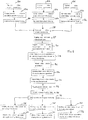
- Figure 2 is a diagram representing the steps performed during a video conference in a system of figure 1 .
- a first video routing participant 3A has a personal computer 4A as video routing client device 4
- a second video routing participant 3B has a smartphone 4B as video routing client device 4
- a third video routing participant 3C has a tablet 4C as video routing client device 4 (see figure 1 ).
- each video routing client device 4 generates (steps 24A, 24B and 24C) a captured video stream 7 representing its participant in his/her own environment.
- Each video routing device 4 establishes a bidirectional communication channel 8 with the router 16 of the MCVRS 5 (steps 25A, 25B and 25C).
- the captured video stream 7 of each video routing client 4 device is send (step 26A, 26B and 26C) to the router 16 via the established communication channel 8.
- the router 16 sends (step 27) each captured video stream 7 from the video routing devices 4 to the other video routing client devices 4 and to the tagging agent block 17.
- a first captured video stream 7A from the first video routing client 4A is sent to the second video routing client device 4B, to the third client device 4C and to the tagging agent block 17.
- a second captured video stream 7B, from the second video routing client device 4B and including data 20, is sent to the first client video routing device 7A, to the third video routing client device 4C and to the tagging agent block 17.
- a third captured video stream from the third video routing client device 4C is sent to the first video routing client device 4A, to the second video routing client device 4B and to the tagging agent block 17.
- Each captured video stream 7 is tagged by the tagging agent block 17 (step 28).
- the tagging agent block 17 tags also said additional information data 20.
- the tagging agent block 17 adds a red frame 29 (see figures 3A and 3B ) around each image of the captured video streams 7.
- the tagging agent block 17 sends the tagged video streams 21, including tagged additional information data 22, to the communication agent block 19 (step 30).
- the communication agent block 19 establishes a bidirectional communication channel 14 with the MCU 12 for each tagged video stream 21 (step 31).
- a first communication channel 14A carries a first tagged video stream 21A
- a second communication channel 14B carries a second tagged video stream 21B including tagged additional information data 22
- a third communication channel 14C carries a third tagged video stream 21C.
- the MCU 12 generates the mixed video stream 15 with the tagged video streams 21 and its own captured video stream 13 (step 32).
- the mixed video stream 15 includes the three tagged video streams 21 and the captured video stream 13 from the mixing client device 2 joined together.
- a display device of the mixing device 2 displays the mixed video stream 15.
- the MCU 12 sends the mixed video stream 15 on the three already established bidirectional communication channels 14 (step 33).
- the communication agent block 19 receives the mixed video stream 15.
- the communication agent block 19 transmits the mixed video stream 15 to the tag detector block 18 (step 34).
- the tag detector block 18 analyses each image of the mixed video streams 15. More specifically, the tag detector block 18 analyses each image of the mixed video stream 15 to detect each portions of the image which comprises a tag as added by the tagging agent block 17 (step 35). During this step, the tagging agent detects all portions which are surrounded by a red frame. The images of the three tagged video stream 21 and the tagged additional information data 22 are detected by the tag detector block 18. Then, the tag detector block 18 cuts-out portion of the images which have not been detected as tagged by the tagging agent block 17 (step 36). As an image of the mixed video stream 15 includes three tagged images and tagged additional information data 22 joined together, only one portion of such image is cut-out as having not been tagged by the tagging agent block 17.
- Such cut-out image corresponds to an image of the captured video stream 13 from the mixing client device 2.
- the tag detector block 18 generates the extracted video stream 23 with the cut-out images of the mixed video stream 15 (step 37).
- the tag detector block sends said extracted video stream 23 to the communication agent block 19 which transmits it to the tagging agent block 17.
- the tagging agent block 17 then transmits to the router 16 the extracted video stream 23.
- the router 16 uses the established communication channels 8 to send the extracted video stream 23 to each video routing client 4 (step 38).
- Each video routing client generates a mixed video stream 40 with the captured video stream from its own capture device 2 (step 39), the capture video streams from the other video routing client devices and the extracted video stream 23 of the mixed video stream 15.
- a mixed video stream 40 generated by each video routing client device 4 is similar to the mixed video stream 15 generated by the mixing client, each one representing all the participants 1 and 3 joined in a same mixed video stream 15 or 40.
- Figures 3A is an image from a mixed video stream including tagged portions during a conference using the system of figure 1 .
- An image 41 from a mixed video stream as represented in figure 3A includes a first tagged image portion 42A representing a first video routing participant 3A, a second tagged image portion 42B representing a second video routing participant 3B, a third image portion 42C representing a third video routing participant 3C and a fourth portion 42D representing the tagged additional information data 22.
- the image 41 also includes a mixing portion 43 representing mixing participant 1.
- the tag detector block 18 detects the red frame 29 around the tagged portions 42. As these tagged portions 42 have been detected, the tag detector block 18 cuts-out the non-tagged portion of the image. Typically, the tag detector block 18 cuts-out the mixing portion 43. The tag detector block 18 extracts an image corresponding to the mixing portion 43 and integrates the extracted image to an extracted video stream representing the mixing participant.
- Figures 3B is an image from a mixed video stream including tagged portions and disjoint non-tagged portions during a conference.
- An image 44 from a mixed video stream as represented in figure 3B includes a first tagged image portion 45A representing a first video routing participant and a second tagged image portion 45B representing a second video routing participant and a tagged additional information portion 45C.
- the image 44 also includes a first mixing portion 46A and a second mixing portion 46B, each one representing a respectively a first and a second mixing participant.
- the tag detector block 18 detects the tagged portions 45. As these tagged portions 45 have been detected, the tag detector block 18 cuts-out the non-tagged portions 46 of the image 44. Typically, the tag detector block 18 cuts-out the first mixing portion 46A and the second mixing portion 46B. The tag detector block 18 detects that these two non-tagged portions are disjoint in the image 44, the first mixing portion 46A being separated from the second mixing portion 46B by the first video routing portion 45B. As two disjoint portions of the image are detected as being not tagged, the tag detector block 18 generates two different images corresponding respectively to the first mixing portion 46A and to the second mixing portion 46B. These two images are integrated to two different extracted video streams 23, each one representing respectively the first and the second mixing participant.
- the mixed video stream 15 generated by the mixing client 2 includes additional information data which is not tagged, e.g which is not included in a captured video stream from a video routing client device.
- additional information data is detected by the tag detector block 18 as being non-tagged and then cut-out and inserted in the extracted video stream.
- marks may be inserted in one image or in each image or in every N images of the video stream.
- the mark used by the tagging agent block is a red frame added around the first image of a video stream.
- the tag detector block detects in the first image of a video stream such a red frame, the tag detector considers that the tagged portion in the first image is also a tagged portion in the following images.
Landscapes
- Engineering & Computer Science (AREA)
- Multimedia (AREA)
- Signal Processing (AREA)
- Computer Networks & Wireless Communication (AREA)
- General Engineering & Computer Science (AREA)
- Two-Way Televisions, Distribution Of Moving Picture Or The Like (AREA)
- Data Exchanges In Wide-Area Networks (AREA)
Abstract
- receiving a first client video stream (7) from the video routing client ;
- tagging a video image of the first client video stream received from the video routing client,
- sending, through a bidirectional communication channel (14), the first client video stream (21) to a mixing client,
- receiving, through the bidirectional communication channel with the mixing client, a mixed video stream (15) from said mixing client,
- detecting in the mixed video stream received from the mixing client a video image portion which is different from the tagged video image of the first client video stream,
- extracting the detected video image portion from the mixed video stream,
- generating a second client video stream (23) from the extracted video image portion;
- sending the second client video stream to the video routing client.
Description
- The invention relates to a method of video processing in a multi-participant video-conferencing system.
- Along with the increase of bandwidth capabilities in communication systems, video communication systems have become increasingly popular in both business and residential applications. Indeed, in the case of geographically distributed team collaboration, these systems avoid the travelling of the team collaborators and increase flexibility.
- Videoconferencing technologies use video and audio communication to allow a plurality of people to communicate at a same time, for instance for meeting activities. Furthermore, besides the audio and visual transmission of meeting activities, videoconferencing technologies can be used to share documents and display information.
- Each participant in a videoconference is filmed by a camera which generates a video stream representing the participant in his/her own environment. To create a video conference, two different technologies are generally used.
- In a Video mixing based conference, all incoming video streams from N participants are combined by a Multiparty Conference Unit (MCU) in one mixed video stream. The mixed video stream includes the video streams of all the participants joined together. The mixed video stream is sent to the N participants.
- As opposed to video mixing, video routing technology consists in having each participant send his own video stream to all other parties, which simultaneously decode up to 4 or 5 of them. Each video client device has thus to support receiving and decoding multiple flows.
- In an embodiment, the invention provides a method for interfacing a plurality of videoconferencing client devices comprising a video routing client and a video mixing client, wherein said mixing client comprises a Multiparty Conference Unit able to receive a plurality of client video streams and to generate a mixed video stream by mixing said plurality of client video streams, the method comprising, in a computer server connected to the client devices :
- receiving a first client video stream from the video routing client;
- tagging a video image of the first client video stream received from the video routing client;
- sending, through a bidirectional communication channel, the tagged first client video stream to the mixing client;
- receiving, through the bidirectional communication channel with the mixing client, a mixed video stream from said mixing client;
- detecting in the mixed video stream received from the mixing client a video image portion which is different from a tagged video image of the tagged first client video stream ;
- extracting the detected video image portion from the mixed video stream;
- generating a second client video stream from the extracted video image portion ;
- sending the second client video stream to the video routing client.
- According to embodiments, such method may comprise one or more of the features below.
- In an embodiment, the method further including the steps of
- receiving additional information data, wherein the additional information data is included in the first client video stream ;
- tagging the additional information data received from the video routing client;
- sending the tagged additional information data to the mixing client;
- detecting in the mixed video stream received from the mixing client additional information data which is different from the tagged additional information data ;
- extracting the metadata detected in the mixed video stream ;
- sending the extracted metadata in the second client video stream to the video routing client or to the video routing clients.
- In an embodiment, the method further including the steps of:
- Detecting that the video image portion that is different from the tagged client video image comprises a plurality of disjoint portions;
- generating a plurality of second client video streams, each second client video stream corresponding to a different one of the disjoint portions ;
- sending the plurality of second client video streams to the video routing client.
- In an embodiment, the client video stream received from the video routing client is carried on a bidirectional communication channel carrying a plurality of video streams in both directions.
- In an embodiment, the tagging step includes a step of adding a frame around the video image of the first client video stream received from the video routing client.
- In an embodiment, the tagging step includes a step of adding a transparent layer on the video stream received from the video routing client.
- In an embodiment, the method further comprises the steps of :
- receiving a plurality of first client video stream from a plurality of video routing clients;
- tagging each first client video stream received from the plurality of video routing clients ;
- sending, through a plurality of bidirectional communication channels, each tagged first client video stream to the mixing client;
- detecting in the mixed video stream received from the mixing client the video image portion which is different from each of the plurality of tagged first client video streams.
- In an embodiment, the method further includes the steps of:
- receiving a plurality of additional information data from a plurality of first video routing client;
- tagging the plurality of additional information data received from the plurality of first video routing client.
- In an embodiment, the invention also provides a video processing server for interfacing a plurality of videoconferencing clients devices comprising a video routing client and a video mixing client, wherein said mixing client comprises a Multiparty Conference Unit able to receive a plurality of client video streams to generate a mixed video stream by mixing said plurality of client video streams, the video processing sever including :
- a router able to
○ receive a first client video stream from a video routing client device,
○ Send to the video routing client a second client video stream generated from a video image portion extracted from mixed video stream received from the mixing client; - a tagging agent block able to mark the first client video stream received from the video routing clients,
- a communication block able to
- ○ send, in a bidirectional communication channels carrying the tagged first client video stream to the mixing client, and to
- ○ receive a mixed video stream generated by the mixing client including tagged first client video stream sent to said mixing client;
- a tag detector block able to
- ○ detect a video image portion of the mixed video stream received from the mixing client which is different from the tagged first client video stream,
- ○ extract the detected image portion in the mixed video stream received from the mixing client.
- In other embodiments, the first client video stream from the video routing client and the second video stream sent to the video routing client are carried on a bidirectional communication channel established between the server and the video routing client.
- In an embodiment, the invention also provides a computer program comprising computer-executable instructions that perform the above-mentioned method when executed, and a computer that comprises said computer program.
- The invention originates from the observation that, despite of an installed base market dominated by mixing compatible video systems, a significant part of them embedding an up to four ports MCU, multiparty video conferencing is shifting from mixing to video routing technology. An idea on which the invention is based is to include such a video mixing based system in routed multiparty video sessions, in which multiple video flows, sometimes including a presentation sharing data, are exchanged among all parties.
- These and other aspects of the invention will be apparent from and elucidated with reference to the embodiments described hereinafter, by way of example, with reference to the drawings.
-
Figure 1 illustrates functionally an embodiment of a video conferencing system architecture in the case wherein three video routing clients are participating in a video conference with a mixing client comprising an integrated capture device. -
Figure 2 is a diagram representing the steps performed by a server in a system offigure 1 . -
Figure 3A is a schematically representation of an image of a mixed video stream generated by the mixing client offigure 1 . -
Figure 3B is a schematically representation of an image of a mixed video stream generated by a mixing client having two different capture devices directly connected to the MCU ; -
Figure 1 illustrates an embodiment of a video conferencing system architecture in the case wherein four persons are participating in a video conference. - In
figure 1 , a mixing participant 1 uses amixing client device 2. Threevideo routing participants 3 use each one a videorouting client device 4. Mixingclient device 2 and video routing client devices are connected to a Mixing Compatible Video Routing Server 5 (MCVRS). Each client device may be for instance a personal computer, a mobile phone, a tablet or any other device. The participants, and their respective client devices, are located in different places and have a video conference together. - Each video
routing client device 4 has a capture device 6. The capture device 6 is, for instance, a camera 6 which captures a video stream 7 of itsrouting participant 3 in his/her own environment. Each videorouting client device 4 has a communication port able to establish abidirectional communication channel 8 with the MCVRS 5. Such acommunication channel 8, established between the videorouting client device 4 and the MCVRS 5, is able to carry a plurality of video streams in both directions. In use, the videorouting client device 4 sends its captured video stream 7 to the MCVRS 5 and receives video streams corresponding to the video streams captured by other participants. Videorouting client device 4 is able to mix its own captured video stream and received video streams carried on thecommunication channels 8 in a mixed video stream. An image of such mixed video stream includes the simultaneous images of all the video streams joined together (seefigure 2 ). - The mixing
client 2 comprises a capture device 9, an encoder block 10, a decoder block 11 and an embedded MCU 12. The capture device 9 is, for instance, a camera 9 which captures avideo stream 13 of the mixing participant 1 in his/her environment. The encoder block 10 encodes the capturedvideo stream 13 and transmits it to the MCU 12. - The MCU 12 has a plurality of communication ports. Each port of the MCU 12 permits to establish a
communication channel 14 between the mixingclient device 2 and the MCVRS 5. Eachcommunication channel 14 established between the MCU 12 and the MCVRS 5 is a bidirectional channel able to carry one video stream, and optionally a further data stream, in both directions. The MCU 12 mixes the video stream captured by the capture device 9 of the mixingclient device 2 and the received video streams carried on thecommunication channels 14 into amixed video stream 15. An image of such amixed video stream 15 includes the simultaneous images of all the video streams used to generate themixed video stream 15 joined together. Themixed video stream 15 is sent to the decoder block 11. Themixed video stream 15 is also sent in the establishedcommunication channel 14 to the MCVRS 5. - The decoder block 11 decodes the
mixed video stream 15. The decoded video stream is displayed on a display device of the mixingclient device 2, for instance a computer screen or a TV. - If the mixing
client device 2 were merely connected to avideo routing client 4 device, the videorouting client device 4 would send to the mixingclient device 2 its captured video stream, then the mixingclient device 2 would include the video stream received from the videorouting client device 4 in a mixed video stream and the mixingclient device 2 would send back the mixed video stream to the videorouting client device 4. The videorouting client device 4 would then generate a mixed video stream including its own captured video stream and the mixed video stream received from the mixingclient device 2. Such a mixed video stream generated by the videorouting client device 4 would include the video routing client device captured video stream two times, once from its own captured video stream and once from the mixed video stream from the mixingclient device 2. - To avoid this in the video conferencing system represented in
figure 1 , the MCVRS 5 includes arouter 16, a taggingblock 17, a tag detection block 18 and a communication agent block 19. - The
router 16 has a plurality of ports able to establishbidirectional communication channels 8 with the videorouting client devices 4. Each establishedbidirectional communication channel 8 established can carry a plurality of video streams in both directions. In fact,router 16 receives a respective video stream, and optionally data, from each videorouting client device 4 and sends it back to all other videorouting client devices 4. Therouter 16 also sends the video streams received from everyvideo routing client 4 to thetagging agent block 17. - The tagging
agent block 17 performs the tagging of the video images. Tagging can be any marking technology, and can range from sophisticated transparent technology, to simple addition of a signed/specific frame around each image of the video stream. When the incoming video stream includesadditional information data 20, e.g documents to be shared by the participants, theadditional data 20 is also tagged. The taggingagent block 17 sends each tagged video stream to the communication agent block 19. - The communication agent block 19 establishes as
many communication channels 14 as needed with the MCU 12 embedded in the mixingclient device 2, i.e onebidirectional channel 14 per videorouting client device 4, with a maximum depending on the MCU 12 capability. Eachcommunication channel 14 between the communication agent block 19 and the MCU 12 carries one video stream, and optionally a further data stream, in both directions. The communication agent block 19 sends the tagged video streams 21, and optionally taggedadditional information data 22, to the MCU 12. The tagged video streams 21 sent by the communication agent block 19 to the MCU 12 are the ones received from the taggingagent block 17. The Communication agent block 19 receives from the MCU 12 themixed video stream 15 generated by the MCU 12. The communication agent block 19 transmitsmixed video stream 15 to the Tag detector block 18. - The tag detector block 18 is able to detect which parts of each image in the mixed video stream correspond to images previously tagged by the tagging
agent block 17. The Tag detector block 18 receives themixed video stream 15 from the communication agent block 19. Tag detector block 18 detects the tagged areas in each image of themixed video stream 15. Once tagged areas have been identified in an image of themixed video stream 15, the tag agent block 18 cuts-out the non-tagged areas from the image of themixed video stream 15. The cut-out portion or portions is used to generate a new image corresponding to an image captured by the capture device 9 included in themixing device 2. An extractedvideo stream 23 is generated with the cut-out portion or portions of themixed video stream 15. Said extractedvideo stream 23 is sent back to the communication agent block 19. - The tag detector block 18 generates a video stream corresponding to each disjoined portion of the
mixed video stream 15 which has not been tagged by the taggingagent block 17. If the tag detector block 18 detects only one non-tagged area in the images of themixed video stream 15, the tag detector block generates only one extractedvideo stream 23. If the tag detector block 18 detects a plurality of disjoined non-tagged areas in the images of themixed video stream 15, the tag detector block 18 generates one extractedvideo stream 23 for each detected non-tagged portion of the image. -
Figure 2 is a diagram representing the steps performed during a video conference in a system offigure 1 . - In this system, a first
video routing participant 3A has apersonal computer 4A as videorouting client device 4, a second video routing participant 3B has a smartphone 4B as videorouting client device 4 and a third video routing participant 3C has a tablet 4C as video routing client device 4 (seefigure 1 ). - As explained above, each video
routing client device 4 generates (steps 24A, 24B and 24C) a captured video stream 7 representing its participant in his/her own environment. Eachvideo routing device 4 establishes abidirectional communication channel 8 with therouter 16 of the MCVRS 5 (steps 25A, 25B and 25C). The captured video stream 7 of eachvideo routing client 4 device is send (step 26A, 26B and 26C) to therouter 16 via the establishedcommunication channel 8. Therouter 16 sends (step 27) each captured video stream 7 from thevideo routing devices 4 to the other videorouting client devices 4 and to thetagging agent block 17. Typically, as shown infigure 1 , a first capturedvideo stream 7A from the firstvideo routing client 4A is sent to the second video routing client device 4B, to the third client device 4C and to thetagging agent block 17. A second captured video stream 7B, from the second video routing client device 4B and includingdata 20, is sent to the first clientvideo routing device 7A, to the third video routing client device 4C and to thetagging agent block 17. A third captured video stream from the third video routing client device 4C is sent to the first videorouting client device 4A, to the second video routing client device 4B and to thetagging agent block 17. - Each captured video stream 7 is tagged by the tagging agent block 17 (step 28). As the capture video stream 7B of the second video routing client device includes
additional information data 20, the taggingagent block 17 tags also saidadditional information data 20. The taggingagent block 17 adds a red frame 29 (seefigures 3A and 3B ) around each image of the captured video streams 7. The taggingagent block 17 sends the tagged video streams 21, including taggedadditional information data 22, to the communication agent block 19 (step 30). As the MCU 12 in the mixingclient device 2 supportscommunication channels 14 carrying only one video stream, and optionally a further data stream, in both direction, the communication agent block 19 establishes abidirectional communication channel 14 with the MCU 12 for each tagged video stream 21 (step 31). As shown infigure 1 , a first communication channel 14A carries a first tagged video stream 21A, a second communication channel 14B carries a second tagged video stream 21B including taggedadditional information data 22 And a third communication channel 14C carries a third tagged video stream 21C. - The MCU 12 generates the
mixed video stream 15 with the tagged video streams 21 and its own captured video stream 13 (step 32). Themixed video stream 15 includes the three tagged video streams 21 and the capturedvideo stream 13 from the mixingclient device 2 joined together. A display device of themixing device 2 displays themixed video stream 15. The MCU 12 sends themixed video stream 15 on the three already established bidirectional communication channels 14 (step 33). - The communication agent block 19 receives the
mixed video stream 15. The communication agent block 19 transmits themixed video stream 15 to the tag detector block 18 (step 34). - The tag detector block 18 analyses each image of the mixed video streams 15. More specifically, the tag detector block 18 analyses each image of the
mixed video stream 15 to detect each portions of the image which comprises a tag as added by the tagging agent block 17 (step 35). During this step, the tagging agent detects all portions which are surrounded by a red frame. The images of the three tagged video stream 21 and the taggedadditional information data 22 are detected by the tag detector block 18. Then, the tag detector block 18 cuts-out portion of the images which have not been detected as tagged by the tagging agent block 17 (step 36). As an image of themixed video stream 15 includes three tagged images and taggedadditional information data 22 joined together, only one portion of such image is cut-out as having not been tagged by the taggingagent block 17. Such cut-out image corresponds to an image of the capturedvideo stream 13 from the mixingclient device 2. The tag detector block 18 generates the extractedvideo stream 23 with the cut-out images of the mixed video stream 15 (step 37). The tag detector block sends said extractedvideo stream 23 to the communication agent block 19 which transmits it to thetagging agent block 17. The taggingagent block 17 then transmits to therouter 16 the extractedvideo stream 23. Therouter 16 uses the establishedcommunication channels 8 to send the extractedvideo stream 23 to each video routing client 4 (step 38). - Each video routing client generates a mixed video stream 40 with the captured video stream from its own capture device 2 (step 39), the capture video streams from the other video routing client devices and the extracted
video stream 23 of themixed video stream 15. A mixed video stream 40 generated by each video routing client device 4 (seefigure 1 ) is similar to themixed video stream 15 generated by the mixing client, each one representing all theparticipants 1 and 3 joined in a samemixed video stream 15 or 40. -
Figures 3A is an image from a mixed video stream including tagged portions during a conference using the system offigure 1 . - An
image 41 from a mixed video stream as represented infigure 3A includes a first taggedimage portion 42A representing a firstvideo routing participant 3A, a second taggedimage portion 42B representing a second video routing participant 3B, athird image portion 42C representing a third video routing participant 3C and a fourth portion 42D representing the taggedadditional information data 22. Theimage 41 also includes a mixingportion 43 representing mixing participant 1. - During its analyses, the tag detector block 18 detects the
red frame 29 around the taggedportions 42. As these taggedportions 42 have been detected, the tag detector block 18 cuts-out the non-tagged portion of the image. Typically, the tag detector block 18 cuts-out the mixingportion 43. The tag detector block 18 extracts an image corresponding to the mixingportion 43 and integrates the extracted image to an extracted video stream representing the mixing participant. -
Figures 3B is an image from a mixed video stream including tagged portions and disjoint non-tagged portions during a conference. - An
image 44 from a mixed video stream as represented infigure 3B includes a first taggedimage portion 45A representing a first video routing participant and a second tagged image portion 45B representing a second video routing participant and a tagged additional information portion 45C. Theimage 44 also includes afirst mixing portion 46A and asecond mixing portion 46B, each one representing a respectively a first and a second mixing participant. - During its analyses, the tag detector block 18 detects the tagged portions 45. As these tagged portions 45 have been detected, the tag detector block 18 cuts-out the non-tagged portions 46 of the
image 44. Typically, the tag detector block 18 cuts-out thefirst mixing portion 46A and thesecond mixing portion 46B. The tag detector block 18 detects that these two non-tagged portions are disjoint in theimage 44, thefirst mixing portion 46A being separated from thesecond mixing portion 46B by the first video routing portion 45B. As two disjoint portions of the image are detected as being not tagged, the tag detector block 18 generates two different images corresponding respectively to thefirst mixing portion 46A and to thesecond mixing portion 46B. These two images are integrated to two different extracted video streams 23, each one representing respectively the first and the second mixing participant. - In an embodiment, the
mixed video stream 15 generated by the mixingclient 2 includes additional information data which is not tagged, e.g which is not included in a captured video stream from a video routing client device. Such additional information data is detected by the tag detector block 18 as being non-tagged and then cut-out and inserted in the extracted video stream. - To tag an item in a video stream, marks may be inserted in one image or in each image or in every N images of the video stream. In an embodiment, the mark used by the tagging agent block is a red frame added around the first image of a video stream. When the tag detector block detects in the first image of a video stream such a red frame, the tag detector considers that the tagged portion in the first image is also a tagged portion in the following images. In another embodiment, only one image every N images, with for instance N=10, of a video stream is tagged, each tagged portion being defined for the tagged image of a video stream and the N following images.
- The invention is not limited to the described embodiments. The appended claims are to be construed as embodying all modification and alternative constructions that may be occurred to one skilled in the art, which fairly fall within the basic teaching here, set forth. The use of the verb "to comprise" or "to include" and its conjugations does not exclude the presence of elements or steps other than those stated in a claim. Furthermore, the use of the article "a" or "an" preceding an element or step does not exclude the presence of a plurality of such elements or steps. The invention may be implemented by means of hardware as well as software. The same item of hardware may represent several "means".
Claims (10)
- A method for interfacing a plurality of videoconferencing client devices comprising a video routing client (4) and a video mixing client (2), wherein said mixing client comprises a Multiparty Conference Unit (12) able to receive a plurality of client video streams (20) and to generate a mixed video stream (15) by mixing said plurality of client video streams the method comprising, in a computer server connected to the client devices:- receiving a first client video stream (7) from the video routing client ;- tagging a video image of the first client video stream received from the video routing client,- sending, through a bidirectional communication channel (14), the first client video stream (21) to the mixing client,- receiving, through the bidirectional communication channel with the mixing client, a mixed video stream (15) from said mixing client,- detecting in the mixed video stream received from the mixing client a video image portion which is different from the tagged video image of the first client video stream,- extracting the detected video image portion from the mixed video stream,- generating a second client video stream (23) from the extracted video image portion;- sending the second client video stream to the video routing client.
- A method according to claim anyone of claims 1 or 2, the method further including the steps of- receiving additional information data (20), wherein the additional information data is included in the first client video stream ;- tagging the additional information data received from the video routing client;- sending the tagged additional information data (22) to the mixing client,- detecting in the mixed video stream received from the mixing client additional information data which is different from the tagged additional information data,- extracting the additional information data detected in the mixed video stream,- sending the extracted additional information data in the second client video stream to the video routing client or to the video routing clients.
- A method according to any one of claims 1 to 2, the method further including the steps of :- Detecting that the video image portion that is different from the tagged client video image comprises a plurality of disjoint portions (29, 30);- generating a plurality of second client video streams, each second client video stream corresponding to a different one of the disjoint portions;- sending the plurality of second client video streams to the video routing client.
- A method according to anyone of claims 1 to 3, wherein the client video stream received from the video routing client is carried on a bidirectional communication channel (8) carrying a plurality of video streams in both directions.
- A method according to anyone of claims 1 to 4, wherein the tagging step includes a step of adding a frame (24) around the video image of the first client video stream received from the video routing client.
- A method according to anyone of claims 1 to 4, wherein the tagging step includes a step of adding a transparent layer on the video stream received from the video routing client.
- A method according to anyone of claims 1 to 6, wherein the method further comprises the steps of :- receiving a plurality of first client video streams (7A, 7B, 7C)from a plurality of video routing clients (4A, 4B, 4C);- tagging each first client video stream received from the plurality of video routing clients;- sending, through a plurality of bidirectional communication channels, each tagged first client video stream (20A, 20B, 20C) to the mixing client,- detecting in the mixed video stream received from the mixing client the video image portion which is different from each of the plurality of tagged first client video streams.
- A method according to claim 7, wherein the method further includes the steps of :- receiving a plurality of additional information data from a plurality of first video routing client ;- tagging the plurality of additional information data received from the plurality of first video routing client ;
- A video processing server for interfacing a plurality of videoconferencing clients devices comprising a video routing client and a video mixing client, wherein said mixing client comprises a Multiparty Conference Unit able to receive a plurality of client video streams to generate a mixed video stream by mixing said plurality of client video streams, the video processing sever including :- a router (16) able to○ receive a first client video stream from the video routing client device,○ Send to the video routing client a second client video stream generated from a video image portion extracted from a mixed video stream received from the mixing client;- a tagging agent block (17) able to mark the first client video stream received from the video routing client,- a communication block (19) able to○ send in a bidirectional communication channel the tagged first client video stream to the mixing client, and to○ receive a mixed video stream generated by the mixing client including tagged first client video stream sent to said mixing client;- a tag detector block (18) able to○ detect a video image portion of the mixed video stream received from the mixing client which is different from the tagged first client video stream, and○ extract the detected image portion in the mixed video stream received from the mixing client.
- The Video processing server according to claim 9, wherein the first client video stream from the video routing client and the second client video stream sent to the video routing client are carried on a bidirectional communication channel established between the server and the video routing client.
Priority Applications (6)
| Application Number | Priority Date | Filing Date | Title |
|---|---|---|---|
| EP13306152.3A EP2838257B1 (en) | 2013-08-15 | 2013-08-15 | A method for generating an immersive video of a plurality of persons |
| KR1020167003420A KR20160030561A (en) | 2013-08-15 | 2014-07-10 | A method for generating an immersive video of a plurality of persons |
| CN201480044148.3A CN105453557A (en) | 2013-08-15 | 2014-07-10 | A method for generating an immersive video of a plurality of persons |
| JP2016533851A JP6291580B2 (en) | 2013-08-15 | 2014-07-10 | A method for generating immersive videos of multiple people |
| PCT/EP2014/064865 WO2015022122A1 (en) | 2013-08-15 | 2014-07-10 | A method for generating an immersive video of a plurality of persons |
| US14/911,527 US9571792B2 (en) | 2013-08-15 | 2014-07-10 | Method for generating an immersive video of a plurality of persons |
Applications Claiming Priority (1)
| Application Number | Priority Date | Filing Date | Title |
|---|---|---|---|
| EP13306152.3A EP2838257B1 (en) | 2013-08-15 | 2013-08-15 | A method for generating an immersive video of a plurality of persons |
Publications (2)
| Publication Number | Publication Date |
|---|---|
| EP2838257A1 true EP2838257A1 (en) | 2015-02-18 |
| EP2838257B1 EP2838257B1 (en) | 2016-04-06 |
Family
ID=49054478
Family Applications (1)
| Application Number | Title | Priority Date | Filing Date |
|---|---|---|---|
| EP13306152.3A Not-in-force EP2838257B1 (en) | 2013-08-15 | 2013-08-15 | A method for generating an immersive video of a plurality of persons |
Country Status (6)
| Country | Link |
|---|---|
| US (1) | US9571792B2 (en) |
| EP (1) | EP2838257B1 (en) |
| JP (1) | JP6291580B2 (en) |
| KR (1) | KR20160030561A (en) |
| CN (1) | CN105453557A (en) |
| WO (1) | WO2015022122A1 (en) |
Families Citing this family (10)
| Publication number | Priority date | Publication date | Assignee | Title |
|---|---|---|---|---|
| EP2824913A1 (en) * | 2013-07-09 | 2015-01-14 | Alcatel Lucent | A method for generating an immersive video of a plurality of persons |
| US10204397B2 (en) | 2016-03-15 | 2019-02-12 | Microsoft Technology Licensing, Llc | Bowtie view representing a 360-degree image |
| US9686510B1 (en) | 2016-03-15 | 2017-06-20 | Microsoft Technology Licensing, Llc | Selectable interaction elements in a 360-degree video stream |
| US9866400B2 (en) | 2016-03-15 | 2018-01-09 | Microsoft Technology Licensing, Llc | Action(s) based on automatic participant identification |
| US11386562B2 (en) | 2018-12-28 | 2022-07-12 | Cyberlink Corp. | Systems and methods for foreground and background processing of content in a live video |
| GB2580668A (en) * | 2019-01-22 | 2020-07-29 | Starleaf Ltd | A system for connecting a computer with a video conference endsystem |
| JP2020202531A (en) * | 2019-06-13 | 2020-12-17 | パナソニックIpマネジメント株式会社 | Conference system, video conferencing device, and video processing method |
| CN114374816A (en) * | 2020-10-19 | 2022-04-19 | 中国移动通信集团浙江有限公司 | Information interaction method based on video conference, server and terminal equipment |
| CN112532913A (en) * | 2020-11-30 | 2021-03-19 | 广州虎牙科技有限公司 | Video mixing method, video system and server |
| US20250063138A1 (en) * | 2021-12-21 | 2025-02-20 | Canon U.S.A., Inc. | Apparatus and method for controlling an online meeting |
Citations (3)
| Publication number | Priority date | Publication date | Assignee | Title |
|---|---|---|---|---|
| US20060215765A1 (en) * | 2005-03-25 | 2006-09-28 | Cherng-Daw Hwang | Split screen video in a multimedia communication system |
| US20060244819A1 (en) * | 2005-04-28 | 2006-11-02 | Thomas Pun | Video encoding in a video conference |
| EP2288104A1 (en) * | 2009-08-19 | 2011-02-23 | Avaya Inc. | Flexible decomposition and recomposition of multimedia conferencing streams using real-time control information |
Family Cites Families (8)
| Publication number | Priority date | Publication date | Assignee | Title |
|---|---|---|---|---|
| JPH08181958A (en) * | 1994-12-22 | 1996-07-12 | Canon Inc | Communication conference system, communication terminal device and camera operation device |
| JP2000115737A (en) * | 1998-10-08 | 2000-04-21 | Mitsubishi Electric Corp | Multipoint video conference system |
| US20040022202A1 (en) * | 2002-08-05 | 2004-02-05 | Chih-Lung Yang | Method and apparatus for continuously receiving images from a plurality of video channels and for alternately continuously transmitting to each of a plurality of participants in a video conference individual images containing information concerning each of said video channels |
| JP2005197945A (en) * | 2004-01-06 | 2005-07-21 | Tietech Co Ltd | Video conference system |
| US8861701B2 (en) * | 2005-04-28 | 2014-10-14 | Apple Inc. | Multi-participant conference adjustments |
| JP2008085677A (en) * | 2006-09-27 | 2008-04-10 | Toshiba Corp | Information control apparatus, information synthesis apparatus, and program |
| CN101877775A (en) * | 2010-04-06 | 2010-11-03 | 中兴通讯股份有限公司 | Telepresence system and its camera group |
| US8638354B2 (en) * | 2010-10-01 | 2014-01-28 | Creative Technology Ltd | Immersive video conference system |
-
2013
- 2013-08-15 EP EP13306152.3A patent/EP2838257B1/en not_active Not-in-force
-
2014
- 2014-07-10 CN CN201480044148.3A patent/CN105453557A/en active Pending
- 2014-07-10 US US14/911,527 patent/US9571792B2/en not_active Expired - Fee Related
- 2014-07-10 WO PCT/EP2014/064865 patent/WO2015022122A1/en not_active Ceased
- 2014-07-10 KR KR1020167003420A patent/KR20160030561A/en not_active Ceased
- 2014-07-10 JP JP2016533851A patent/JP6291580B2/en not_active Expired - Fee Related
Patent Citations (3)
| Publication number | Priority date | Publication date | Assignee | Title |
|---|---|---|---|---|
| US20060215765A1 (en) * | 2005-03-25 | 2006-09-28 | Cherng-Daw Hwang | Split screen video in a multimedia communication system |
| US20060244819A1 (en) * | 2005-04-28 | 2006-11-02 | Thomas Pun | Video encoding in a video conference |
| EP2288104A1 (en) * | 2009-08-19 | 2011-02-23 | Avaya Inc. | Flexible decomposition and recomposition of multimedia conferencing streams using real-time control information |
Also Published As
| Publication number | Publication date |
|---|---|
| WO2015022122A1 (en) | 2015-02-19 |
| US20160191852A1 (en) | 2016-06-30 |
| KR20160030561A (en) | 2016-03-18 |
| EP2838257B1 (en) | 2016-04-06 |
| JP2016530810A (en) | 2016-09-29 |
| CN105453557A (en) | 2016-03-30 |
| JP6291580B2 (en) | 2018-03-14 |
| US9571792B2 (en) | 2017-02-14 |
Similar Documents
| Publication | Publication Date | Title |
|---|---|---|
| EP2838257B1 (en) | A method for generating an immersive video of a plurality of persons | |
| CN102638672B (en) | Automatic video layout for multi-stream multi-site telepresence conferencing systems | |
| RU2595263C1 (en) | Method of media interaction, device and system for multithreaded conference communication | |
| US8803991B2 (en) | Snapshot capture in video stream | |
| US20140184721A1 (en) | Method and Apparatus for Performing a Video Conference | |
| US9609273B2 (en) | System and method for not displaying duplicate images in a video conference | |
| US20160150187A1 (en) | A method for generating an immersive video of a plurality of persons | |
| CN102291562A (en) | Conference terminal, conference server, conference system and data processing method | |
| WO2014187282A1 (en) | Method, apparatus and video terminal for establishing video conference interface | |
| US20150172558A1 (en) | Video processing method, apparatus, and system | |
| CN108933913A (en) | A kind of video meeting implementing method, device, system and computer storage medium | |
| US20240364840A1 (en) | Immersive scenes | |
| EP3255883A1 (en) | Video conference timeline | |
| WO2015003532A1 (en) | Multimedia conferencing establishment method, device and system | |
| EP2590360A1 (en) | Multi-point sound mixing and long distance view showing method, device and system | |
| WO2014177082A1 (en) | Video conference video processing method and terminal | |
| KR102141104B1 (en) | Method and server for generating videoconference data, and method and device for receiving videoconference data | |
| WO2016206471A1 (en) | Multimedia service processing method, system and device | |
| US20220353437A1 (en) | Systems and methods for immersive scenes | |
| CN111630484A (en) | Virtual window for conference calls | |
| US11838687B2 (en) | Method, computer program and system for configuring a multi-point video conferencing session | |
| CN103096015B (en) | Video processing method and video processing system | |
| CN105516641A (en) | Mobile conference system based on cloud technology and mobile Internet technology | |
| EP3641302A1 (en) | Video conference server capable of providing multi-screen video conference by using plurality of terminals for video conference, and method therefor | |
| WO2013066290A1 (en) | Videoconferencing using personal devices |
Legal Events
| Date | Code | Title | Description |
|---|---|---|---|
| 17P | Request for examination filed |
Effective date: 20130815 |
|
| AK | Designated contracting states |
Kind code of ref document: A1 Designated state(s): AL AT BE BG CH CY CZ DE DK EE ES FI FR GB GR HR HU IE IS IT LI LT LU LV MC MK MT NL NO PL PT RO RS SE SI SK SM TR |
|
| AX | Request for extension of the european patent |
Extension state: BA ME |
|
| PUAI | Public reference made under article 153(3) epc to a published international application that has entered the european phase |
Free format text: ORIGINAL CODE: 0009012 |
|
| R17P | Request for examination filed (corrected) |
Effective date: 20150818 |
|
| RBV | Designated contracting states (corrected) |
Designated state(s): AL AT BE BG CH CY CZ DE DK EE ES FI FR GB GR HR HU IE IS IT LI LT LU LV MC MK MT NL NO PL PT RO RS SE SI SK SM TR |
|
| 17Q | First examination report despatched |
Effective date: 20150918 |
|
| GRAP | Despatch of communication of intention to grant a patent |
Free format text: ORIGINAL CODE: EPIDOSNIGR1 |
|
| INTG | Intention to grant announced |
Effective date: 20151026 |
|
| GRAS | Grant fee paid |
Free format text: ORIGINAL CODE: EPIDOSNIGR3 |
|
| GRAA | (expected) grant |
Free format text: ORIGINAL CODE: 0009210 |
|
| AK | Designated contracting states |
Kind code of ref document: B1 Designated state(s): AL AT BE BG CH CY CZ DE DK EE ES FI FR GB GR HR HU IE IS IT LI LT LU LV MC MK MT NL NO PL PT RO RS SE SI SK SM TR |
|
| REG | Reference to a national code |
Ref country code: GB Ref legal event code: FG4D |
|
| REG | Reference to a national code |
Ref country code: AT Ref legal event code: REF Ref document number: 788920 Country of ref document: AT Kind code of ref document: T Effective date: 20160415 Ref country code: CH Ref legal event code: EP |
|
| REG | Reference to a national code |
Ref country code: IE Ref legal event code: FG4D |
|
| REG | Reference to a national code |
Ref country code: DE Ref legal event code: R096 Ref document number: 602013006176 Country of ref document: DE |
|
| REG | Reference to a national code |
Ref country code: LT Ref legal event code: MG4D Ref country code: NL Ref legal event code: MP Effective date: 20160406 |
|
| REG | Reference to a national code |
Ref country code: AT Ref legal event code: MK05 Ref document number: 788920 Country of ref document: AT Kind code of ref document: T Effective date: 20160406 |
|
| REG | Reference to a national code |
Ref country code: FR Ref legal event code: PLFP Year of fee payment: 4 |
|
| PG25 | Lapsed in a contracting state [announced via postgrant information from national office to epo] |
Ref country code: NL Free format text: LAPSE BECAUSE OF FAILURE TO SUBMIT A TRANSLATION OF THE DESCRIPTION OR TO PAY THE FEE WITHIN THE PRESCRIBED TIME-LIMIT Effective date: 20160406 |
|
| PG25 | Lapsed in a contracting state [announced via postgrant information from national office to epo] |
Ref country code: LT Free format text: LAPSE BECAUSE OF FAILURE TO SUBMIT A TRANSLATION OF THE DESCRIPTION OR TO PAY THE FEE WITHIN THE PRESCRIBED TIME-LIMIT Effective date: 20160406 Ref country code: FI Free format text: LAPSE BECAUSE OF FAILURE TO SUBMIT A TRANSLATION OF THE DESCRIPTION OR TO PAY THE FEE WITHIN THE PRESCRIBED TIME-LIMIT Effective date: 20160406 Ref country code: PL Free format text: LAPSE BECAUSE OF FAILURE TO SUBMIT A TRANSLATION OF THE DESCRIPTION OR TO PAY THE FEE WITHIN THE PRESCRIBED TIME-LIMIT Effective date: 20160406 Ref country code: NO Free format text: LAPSE BECAUSE OF FAILURE TO SUBMIT A TRANSLATION OF THE DESCRIPTION OR TO PAY THE FEE WITHIN THE PRESCRIBED TIME-LIMIT Effective date: 20160706 Ref country code: IS Free format text: LAPSE BECAUSE OF FAILURE TO SUBMIT A TRANSLATION OF THE DESCRIPTION OR TO PAY THE FEE WITHIN THE PRESCRIBED TIME-LIMIT Effective date: 20160806 |
|
| PG25 | Lapsed in a contracting state [announced via postgrant information from national office to epo] |
Ref country code: AT Free format text: LAPSE BECAUSE OF FAILURE TO SUBMIT A TRANSLATION OF THE DESCRIPTION OR TO PAY THE FEE WITHIN THE PRESCRIBED TIME-LIMIT Effective date: 20160406 Ref country code: HR Free format text: LAPSE BECAUSE OF FAILURE TO SUBMIT A TRANSLATION OF THE DESCRIPTION OR TO PAY THE FEE WITHIN THE PRESCRIBED TIME-LIMIT Effective date: 20160406 Ref country code: PT Free format text: LAPSE BECAUSE OF FAILURE TO SUBMIT A TRANSLATION OF THE DESCRIPTION OR TO PAY THE FEE WITHIN THE PRESCRIBED TIME-LIMIT Effective date: 20160808 Ref country code: LV Free format text: LAPSE BECAUSE OF FAILURE TO SUBMIT A TRANSLATION OF THE DESCRIPTION OR TO PAY THE FEE WITHIN THE PRESCRIBED TIME-LIMIT Effective date: 20160406 Ref country code: ES Free format text: LAPSE BECAUSE OF FAILURE TO SUBMIT A TRANSLATION OF THE DESCRIPTION OR TO PAY THE FEE WITHIN THE PRESCRIBED TIME-LIMIT Effective date: 20160406 Ref country code: RS Free format text: LAPSE BECAUSE OF FAILURE TO SUBMIT A TRANSLATION OF THE DESCRIPTION OR TO PAY THE FEE WITHIN THE PRESCRIBED TIME-LIMIT Effective date: 20160406 Ref country code: GR Free format text: LAPSE BECAUSE OF FAILURE TO SUBMIT A TRANSLATION OF THE DESCRIPTION OR TO PAY THE FEE WITHIN THE PRESCRIBED TIME-LIMIT Effective date: 20160707 Ref country code: SE Free format text: LAPSE BECAUSE OF FAILURE TO SUBMIT A TRANSLATION OF THE DESCRIPTION OR TO PAY THE FEE WITHIN THE PRESCRIBED TIME-LIMIT Effective date: 20160406 |
|
| PG25 | Lapsed in a contracting state [announced via postgrant information from national office to epo] |
Ref country code: IT Free format text: LAPSE BECAUSE OF FAILURE TO SUBMIT A TRANSLATION OF THE DESCRIPTION OR TO PAY THE FEE WITHIN THE PRESCRIBED TIME-LIMIT Effective date: 20160406 Ref country code: BE Free format text: LAPSE BECAUSE OF FAILURE TO SUBMIT A TRANSLATION OF THE DESCRIPTION OR TO PAY THE FEE WITHIN THE PRESCRIBED TIME-LIMIT Effective date: 20160406 |
|
| REG | Reference to a national code |
Ref country code: DE Ref legal event code: R097 Ref document number: 602013006176 Country of ref document: DE |
|
| PG25 | Lapsed in a contracting state [announced via postgrant information from national office to epo] |
Ref country code: SK Free format text: LAPSE BECAUSE OF FAILURE TO SUBMIT A TRANSLATION OF THE DESCRIPTION OR TO PAY THE FEE WITHIN THE PRESCRIBED TIME-LIMIT Effective date: 20160406 Ref country code: DK Free format text: LAPSE BECAUSE OF FAILURE TO SUBMIT A TRANSLATION OF THE DESCRIPTION OR TO PAY THE FEE WITHIN THE PRESCRIBED TIME-LIMIT Effective date: 20160406 Ref country code: RO Free format text: LAPSE BECAUSE OF FAILURE TO SUBMIT A TRANSLATION OF THE DESCRIPTION OR TO PAY THE FEE WITHIN THE PRESCRIBED TIME-LIMIT Effective date: 20160406 Ref country code: EE Free format text: LAPSE BECAUSE OF FAILURE TO SUBMIT A TRANSLATION OF THE DESCRIPTION OR TO PAY THE FEE WITHIN THE PRESCRIBED TIME-LIMIT Effective date: 20160406 Ref country code: CZ Free format text: LAPSE BECAUSE OF FAILURE TO SUBMIT A TRANSLATION OF THE DESCRIPTION OR TO PAY THE FEE WITHIN THE PRESCRIBED TIME-LIMIT Effective date: 20160406 |
|
| PLBE | No opposition filed within time limit |
Free format text: ORIGINAL CODE: 0009261 |
|
| STAA | Information on the status of an ep patent application or granted ep patent |
Free format text: STATUS: NO OPPOSITION FILED WITHIN TIME LIMIT |
|
| PG25 | Lapsed in a contracting state [announced via postgrant information from national office to epo] |
Ref country code: SM Free format text: LAPSE BECAUSE OF FAILURE TO SUBMIT A TRANSLATION OF THE DESCRIPTION OR TO PAY THE FEE WITHIN THE PRESCRIBED TIME-LIMIT Effective date: 20160406 |
|
| 26N | No opposition filed |
Effective date: 20170110 |
|
| PG25 | Lapsed in a contracting state [announced via postgrant information from national office to epo] |
Ref country code: MC Free format text: LAPSE BECAUSE OF FAILURE TO SUBMIT A TRANSLATION OF THE DESCRIPTION OR TO PAY THE FEE WITHIN THE PRESCRIBED TIME-LIMIT Effective date: 20160406 |
|
| REG | Reference to a national code |
Ref country code: CH Ref legal event code: PL |
|
| PG25 | Lapsed in a contracting state [announced via postgrant information from national office to epo] |
Ref country code: CH Free format text: LAPSE BECAUSE OF NON-PAYMENT OF DUE FEES Effective date: 20160831 Ref country code: LI Free format text: LAPSE BECAUSE OF NON-PAYMENT OF DUE FEES Effective date: 20160831 |
|
| PG25 | Lapsed in a contracting state [announced via postgrant information from national office to epo] |
Ref country code: SI Free format text: LAPSE BECAUSE OF FAILURE TO SUBMIT A TRANSLATION OF THE DESCRIPTION OR TO PAY THE FEE WITHIN THE PRESCRIBED TIME-LIMIT Effective date: 20160406 |
|
| REG | Reference to a national code |
Ref country code: IE Ref legal event code: MM4A |
|
| PG25 | Lapsed in a contracting state [announced via postgrant information from national office to epo] |
Ref country code: IE Free format text: LAPSE BECAUSE OF NON-PAYMENT OF DUE FEES Effective date: 20160815 |
|
| REG | Reference to a national code |
Ref country code: FR Ref legal event code: PLFP Year of fee payment: 5 |
|
| PG25 | Lapsed in a contracting state [announced via postgrant information from national office to epo] |
Ref country code: LU Free format text: LAPSE BECAUSE OF NON-PAYMENT OF DUE FEES Effective date: 20160815 |
|
| PGFP | Annual fee paid to national office [announced via postgrant information from national office to epo] |
Ref country code: FR Payment date: 20170822 Year of fee payment: 5 |
|
| PG25 | Lapsed in a contracting state [announced via postgrant information from national office to epo] |
Ref country code: HU Free format text: LAPSE BECAUSE OF FAILURE TO SUBMIT A TRANSLATION OF THE DESCRIPTION OR TO PAY THE FEE WITHIN THE PRESCRIBED TIME-LIMIT; INVALID AB INITIO Effective date: 20130815 |
|
| PG25 | Lapsed in a contracting state [announced via postgrant information from national office to epo] |
Ref country code: MT Free format text: LAPSE BECAUSE OF NON-PAYMENT OF DUE FEES Effective date: 20160831 Ref country code: MK Free format text: LAPSE BECAUSE OF FAILURE TO SUBMIT A TRANSLATION OF THE DESCRIPTION OR TO PAY THE FEE WITHIN THE PRESCRIBED TIME-LIMIT Effective date: 20160406 Ref country code: CY Free format text: LAPSE BECAUSE OF FAILURE TO SUBMIT A TRANSLATION OF THE DESCRIPTION OR TO PAY THE FEE WITHIN THE PRESCRIBED TIME-LIMIT Effective date: 20160406 |
|
| PG25 | Lapsed in a contracting state [announced via postgrant information from national office to epo] |
Ref country code: BG Free format text: LAPSE BECAUSE OF FAILURE TO SUBMIT A TRANSLATION OF THE DESCRIPTION OR TO PAY THE FEE WITHIN THE PRESCRIBED TIME-LIMIT Effective date: 20160406 |
|
| PG25 | Lapsed in a contracting state [announced via postgrant information from national office to epo] |
Ref country code: AL Free format text: LAPSE BECAUSE OF FAILURE TO SUBMIT A TRANSLATION OF THE DESCRIPTION OR TO PAY THE FEE WITHIN THE PRESCRIBED TIME-LIMIT Effective date: 20160406 Ref country code: TR Free format text: LAPSE BECAUSE OF FAILURE TO SUBMIT A TRANSLATION OF THE DESCRIPTION OR TO PAY THE FEE WITHIN THE PRESCRIBED TIME-LIMIT Effective date: 20160406 |
|
| REG | Reference to a national code |
Ref country code: DE Ref legal event code: R082 Ref document number: 602013006176 Country of ref document: DE Representative=s name: MENZIETTI WETZEL, DE Ref country code: DE Ref legal event code: R081 Ref document number: 602013006176 Country of ref document: DE Owner name: PROVENANCE ASSET GROUP LLC, PITTSFORD, US Free format text: FORMER OWNER: ALCATEL LUCENT, BOULOGNE BILLANCOURT, FR |
|
| REG | Reference to a national code |
Ref country code: GB Ref legal event code: 732E Free format text: REGISTERED BETWEEN 20190418 AND 20190426 |
|
| PG25 | Lapsed in a contracting state [announced via postgrant information from national office to epo] |
Ref country code: FR Free format text: LAPSE BECAUSE OF NON-PAYMENT OF DUE FEES Effective date: 20180831 |
|
| PGFP | Annual fee paid to national office [announced via postgrant information from national office to epo] |
Ref country code: GB Payment date: 20200909 Year of fee payment: 8 Ref country code: DE Payment date: 20200901 Year of fee payment: 8 |
|
| REG | Reference to a national code |
Ref country code: DE Ref legal event code: R119 Ref document number: 602013006176 Country of ref document: DE |
|
| GBPC | Gb: european patent ceased through non-payment of renewal fee |
Effective date: 20210815 |
|
| PG25 | Lapsed in a contracting state [announced via postgrant information from national office to epo] |
Ref country code: GB Free format text: LAPSE BECAUSE OF NON-PAYMENT OF DUE FEES Effective date: 20210815 Ref country code: DE Free format text: LAPSE BECAUSE OF NON-PAYMENT OF DUE FEES Effective date: 20220301 |