EP2838191A1 - Energy conversion device using change of contact area and contact angle of liquid - Google Patents
Energy conversion device using change of contact area and contact angle of liquid Download PDFInfo
- Publication number
- EP2838191A1 EP2838191A1 EP13850118.4A EP13850118A EP2838191A1 EP 2838191 A1 EP2838191 A1 EP 2838191A1 EP 13850118 A EP13850118 A EP 13850118A EP 2838191 A1 EP2838191 A1 EP 2838191A1
- Authority
- EP
- European Patent Office
- Prior art keywords
- poly
- liquid
- electrode substrate
- contact area
- changes
- Prior art date
- Legal status (The legal status is an assumption and is not a legal conclusion. Google has not performed a legal analysis and makes no representation as to the accuracy of the status listed.)
- Granted
Links
Images


Classifications
-
- H—ELECTRICITY
- H02—GENERATION; CONVERSION OR DISTRIBUTION OF ELECTRIC POWER
- H02N—ELECTRIC MACHINES NOT OTHERWISE PROVIDED FOR
- H02N11/00—Generators or motors not provided for elsewhere; Alleged perpetua mobilia obtained by electric or magnetic means
- H02N11/002—Generators
-
- H—ELECTRICITY
- H02—GENERATION; CONVERSION OR DISTRIBUTION OF ELECTRIC POWER
- H02N—ELECTRIC MACHINES NOT OTHERWISE PROVIDED FOR
- H02N1/00—Electrostatic generators or motors using a solid moving electrostatic charge carrier
- H02N1/06—Influence generators
- H02N1/08—Influence generators with conductive charge carrier, i.e. capacitor machines
-
- H—ELECTRICITY
- H02—GENERATION; CONVERSION OR DISTRIBUTION OF ELECTRIC POWER
- H02N—ELECTRIC MACHINES NOT OTHERWISE PROVIDED FOR
- H02N3/00—Generators in which thermal or kinetic energy is converted into electrical energy by ionisation of a fluid and removal of the charge therefrom
Definitions
- the present invention relates to a method and a device for converting energy using a fluid, more specifically, to a method and a device for converting mechanical energy into electrical energy by applying an reciprocal phenomenon of electrowetting.
- the energy conversion technologies for converting mechanical energy into electrical energy of prior art use a principle that an electrical capacitance is being created in the electrode under a dielectric material by varying the contact area of a liquid metal which is being contact with a dielectric material in accordance with the flow of time.
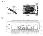
- Fig. 1 is a block diagram of a device of prior art for converting energy using a fluid.
- an electrode is formed to have a consistent pattern on the wall of a thin and long channel, and a dielectric material layer is formed above the electrode.
- a method and a device of prior art for converting energy using a fluid has problems in that the reversible movements in the channel structure must be continuously implemented, and the control is difficult since the two different kinds of immiscible liquids must be used.
- An objective of the present invention is to provide a method and a device for converting energy using a fluid which converts mechanical energy into electrical energy by changing the contact angle and contact area of the liquid contacting the electrode using a physical force.
- an energy converting device utilizing the changes in the contact angle and the contact area of a liquid which includes: a lower and an upper electrodes whose gap therebetween is varying by an external physical force; an ionic liquid or a water whose contact angle and contact area with at least one from said electrodes are varying in accordance with the changes in the gap between said electrodes; and an energy conversion layer, which is formed in at least one of said electrode substrates, and generating electrical energy in accordance with the changes in said contact angle and said contact area.
- a partition for supporting the gap between said lower electrode substrate and said upper electrode substrate, and for isolating the inside and the outside of the device is further included.
- a non-conductive gas disposed between said lower electrode substrate and said upper electrode substrate, which are separated by said partition, is further included.
- said energy conversion layer is formed by stacking an inorganic material layer and an organic material layer, and a hydrophobic material layer is stacked so that the shape of said ionic liquid or water on the electrode substrate in contact with said energy conversion layer or the ionic liquid can be restored to the original shape when the external physical force is removed.
- said partition has at least any one shape of a rectangle, a triangle, an inverted triangle, a circle, an ellipse, or a cylinder, and is formed to be a triangular shape, a rectangular shape, a pentagonal shape, a hexagonal shape, a circular shape, a grid shape, or a honeycomb shape by said partition, so that said energy conversion device can be connected in arrays.
- the gap between said upper electrode substrate and said lower electrode substrate is determined by the size of diameter of said ionic liquid or water.
- said organic material layer includes at least any one material of polymethylmethacrylate(PMMA), polyethylene(PE), polystyrene(PS), polyvinylpyrrolidone(PVP), poly(4-vinylpenol; PVP) or polyethersulfone(PES), poly(4-methoxyphenylacrylate; PMPA), poly(phenylacrylate; PPA), poly(2,2,2-trifluoroethyl methacrylate; PTFMA), cyanoethylpullulan(CYEPL), polyvinyl chloride(PVC), poly(parabanic acid resin; PPA), poly(t-butylstyrene; PTBS), polythienylenevinylene(PTV), polyvinylacetate(PVA), poly(vinyl alcohol; PVA), poly(rmethylstyrene; PAMS), poly(vinyl alcohol)-co-poly(vinyl acetate)-co-pol
- said hydrophobic material layer includes at least any one of silane family material, fluoropolymer material, trichlorosilane, trimethoxysilane, pentafluorophenylpropyltrichlorosilane, (benzyloxy)alkyltrimethoxysilane(BSM-22), (benzyloxy)alkyltrichlorosilane(BTS), hexamethyldisilazane(HMDS), octadecyltrichlorosilane(OTS), octadecyltrimethoxysilane(OTMS), and divinyltetramethyldisiloxane-bis(benzocyclobutene)(BCB).
- said lower electrode substrate or said upper electrode substrate includes an electrode
- said electrode is an inorganic electrode including at least any one of ITO, IGO, chrome, aluminum, indium zinc oxide(IZO), indium gallium zinc oxide(IGZO), ZnO, ZnO 2 or TiO 2 ; or a metal electrode including at least any one of aluminum, iron or copper; or an organic electrode including at least any one of polyethylenedioxythiophene(PEDOT), carbon nano tube(CNT), graphene, polyacetylene, polythiophene(PT), polypyrrole, polyparaphenylene(PPV), polyanilinep), poly sulfur nitride or polyparaphenylenevinylene.
- PEDOT polyethylenedioxythiophene
- said lower electrode substrate or said upper electrode substrate is a metal substrate, a glass substrate, or a polymer material substrate;
- said polymer substrate includes at least any one of polyethylene terephthalate(PET), polyarylate(PAR), polymethylmethacrylate(PMMA), polyethylenenaphthalate(PEN), polyethersulfone(PES), polyimide(PI), polycarbonate(PC) or fiber reinforced plastics(FRP).
- said ionic liquid includes at least any one of NaCl, LiCl, NaNo 3 , Na 2 SiO 3 , AlCl 3 -NaCl, LiCl-KCl, H 2 O, KCL, Na,NaOH H 2 SO 4 , CH 3 COOH, HF, CuSO 4 , ethylene glycol, propylene glycol or AgCl.
- said non-conductive gas includes at least any one of air, oxygen, nitrogen, argon, helium, neon, krypton, xenon, or radon.
- an energy converting device utilizing the changes in the contact angle and the contact area of a liquid
- a lower electrode substrate and an upper electrode substrate whose gap therebetween is being changed by an external physical force
- a conductive liquid whose contact angle and contact area with at least one from the electrode substrates are varying in accordance with the changes in the gap between said electrode substrates
- an energy conversion layer which is formed in said lower electrode substrate or said upper electrode substrate, for generating electrical energy in accordance with said changes.
- a partition for supporting the gap between said lower electrode substrate and said upper electrode substrate, and for isolating the inside and the outside of the device is further included.
- a non-conductive gas disposed between said lower electrode substrate and said upper electrode substrate, which are separated by said partition, is further included.
- said energy conversion layer is formed by stacking an inorganic material layer and an organic material layer, and a hydrophile material layer is stacked on said energy conversion layer so that the shape of said conductive liquid can be restored to the original shape when the external physical force is removed.
- said partition has at least any one shape of a rectangle, a triangle, an inverted triangle, a circle, an ellipse, or a cylinder, and is formed to be a triangular shape, a rectangular shape, a pentagonal shape, a hexagonal shape, a circular shape, a grid shape, or a honeycomb shape by said partition, so that said energy conversion device can be connected in arrays.
- the gap between said upper electrode substrate and said lower electrode substrate is determined by the size of diameter of said conductive liquid.
- said organic material layer includes at least any one material of polymethylmethacrylate(PMMA), polyethylene(PE), polystyrene(PS), polyvinylpyrrolidone(PVP), poly(4-vinylpenol; PVP) or polyethersulfone(PES), poly(4-methoxyphenylacrylate; PMPA), poly(phenylacrylate; PPA), poly(2,2,2-trifluoroethyl methacrylate; PTFMA), cyanoethylpullulan(CYEPL), polyvinyl chloride(PVC), poly(parabanic acid resin; PPA), poly(t-butylstyrene; PTBS), polythienylenevinylene(PTV), polyvinylacetate(PVA), poly(vinyl alcohol; PVA), poly(rmethylstyrene; PAMS), poly(vinyl alcohol)-co-poly(vinyl acetate)-co-pol
- said hydrophobic material layer includes at least any one material of poly acrylic acid(PAA), acrylamides, maleic anhydride copolymers, methacrylate, ethacrylate, amine-functional polymers, amine-functional polymers, polystyrenesulfonate(PSS), vinyl acids, vinyl alcohols, or functional group of -NH, -CO-, amino group -NH2, hydroxyl group -OH or carboxyl group -COOH.
- PAA poly acrylic acid
- acrylamides maleic anhydride copolymers
- methacrylate methacrylate
- amine-functional polymers amine-functional polymers
- polystyrenesulfonate(PSS) polystyrenesulfonate
- vinyl acids vinyl alcohols, or functional group of -NH, -CO-, amino group -NH2, hydroxyl group -OH or carboxyl group -COOH.
- said lower electrode substrate or said upper electrode substrate includes an electrode
- said electrode is an inorganic electrode including at least any one of ITO, IGO, chrome, aluminum, indium zinc oxide(IZO), indium gallium zinc oxide(IGZO), ZnO, ZnO 2 or TiO 2 ; or a metal electrode including at least any one of aluminum, iron or copper; or an organic electrode including at least any one of polyethylenedioxythiophene(PEDOT), carbon nano tube(CNT), graphene, polyacetylene, polythiophene(PT), polypyrrole, polyparaphenylene(PPV), polyanilinep), poly sulfur nitride or polyparaphenylenevinylene.
- PEDOT polyethylenedioxythiophene
- said lower electrode substrate or said upper electrode substrate is a metal substrate, a glass substrate, or a polymer material substrate;
- said polymer substrate includes at least any one of polyethylene terephthalate(PET), polyarylate(PAR), polymethylmethacrylate(PMMA), polyethylenenaphthalate(PEN), polyethersulfone(PES), polyimide(PI), polycarbonate(PC) or fiber reinforced plastics(FRP).
- said conductive liquid may use mercury, lithium, gallium, kalium, NaK, bismuth, tin, natrium, natrium-kalium alloy, and the like; the range of the specific resistivity is 1 ⁇ / ⁇ - to 1000 ⁇ / ⁇ - , and the dielectric constant K is under 5.
- said non-conductive gas includes at least any one of air, oxygen, nitrogen, argon, helium, neon, krypton, xenon, or radon.
- the present invention varies the gap between a pair of electrodes by using an external physical force, and utilizes the resulting changes in the contact angle and the contact area of the liquid in electrical energy generation; thus, it has an effect of implementing an energy conversion device having less failures with a simplified device structure and a reduced manufacturing cost by preventing the channel blocking phenomenon, and by not requiring any lubrication layer, or any complicatedly patterned electrodes on the channel.
- the present invention has an advantage that an effective electrical energy conversion is possible without separately applying an external power source.
- the present invention has an effect on solving the harmful problem to the human body and the environment by using an ionic liquid or a water.
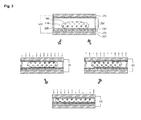
- Fig.2 is a block diagram of a device for converting energy using a fluid according to an exemplary embodiment of the present invention.
- a device for converting energy using a fluid according to an exemplary embodiment of the present invention includes a lower electrode substrate 220 and an upper electrode substrate 210 facing each other, wherein an electrode is disposed on said electrode substrate, and an ionic liquid or a water 260 is located in between the pair of electrodes.
- a non-conductive gas 270 is filled in the space between the lower electrode substrate 220 and the upper electrode substrate 210.
- the distance between the upper electrode substrate and the lower electrode substrate i.e. the gap
- the distance between the upper electrode substrate and the lower electrode substrate is changing when an external physical force is applied, and by the reacting force thereof, the contact area and the contact angle of the ionic liquid and the water, which are being contact with the upper electrode substrate 210 or the lower electrode substrate 220, are changing.
- the contact area of the ionic liquid or water 260 is changing, the capacitance of the electrode is changing, thereby generating electrical energy.
- Fig. 3 is a drawing showing the energy generation process by a device for converting energy using a fluid according to an exemplary embodiment of the present invention.
- the generated electrical energy output of the device for converting energy using a fluid according to an exemplary embodiment of the present invention is 0.
- electrical energy V1, V2 having a consistent polarity are generated as the contact area between the ionic liquid or water 260 and the upper electrode substrate 210 or the lower electrode substrate 220 varies.
- a device for converting energy using a fluid further includes a partition 280 which supports a gap between the lower electrode substrate 220 and the upper electrode substrate 210.
- the partition 280 as illustrated in Fig. 3 , has restoring force or flexibility, wherein shape change occurs by an external physical force, and restores its original shape when the external physical force is removed
- the lower electrode substrate 220 or the upper electrode substrate 210 may also be configured to have restoring force or flexibility.
- the partition 280 is a rigid form
- the contact with the lower electrode substrate 220 or the upper electrode substrate 210 is flexible so the partition 280 may be freely pushed away, or the upper electrode substrate 210 may be flexible while the partition 280 and the lower electrode substrate 220 are rigid, or both may be flexible. It can be configured if the structure is capable of generating change in the contact area where the upper electrode substrate 210 and the ionic liquid or water 260 are in contact, by an external physical force.
- the height of the partition 280, or the gap between the upper electrode substrate and the lower electrode substrate is determined by the size of the diameter of the ionic liquid or water 260, and preferably it would be no more than two times of the diameter of the ionic liquid or water 260. Besides, during the operation of energy conversion, the gap between the upper electrode substrate 210 and the lower electrode substrate 220 must be smaller than the diameter of the ionic liquid or water 260.
- the partition 280 has at least any one shape of a rectangle, a triangle, an inverted triangle, a circle, an ellipse, or a cylinder.
- an energy conversion device can be connected in array form by the partition 280.
- said energy conversion device may have a triangular shape, a rectangular shape, a pentagonal shape, a hexagonal shape, a circular shape, a grid shape, or a honeycomb shape by the partition 280.
- the shape of the partition 280 may be a rectangle, a triangle, an inverted triangle, a circle, an ellipse, or a cylinder, and the shape of a unit cell (comprising an upper plate, a lower plate, a partition, a liquid, and a gas) of the energy conversion device could possibly be a triangular shape, a rectangular shape, a pentagonal shape, a hexagonal shape, a circular shape, a grid shape, or a honeycomb shape.
- an energy conversion device includes an energy conversion layer formed by stacking an inorganic material layer 230 and an organic material layer 240 on the lower electrode substrate 220 and/or the upper electrode substrate 210.
- Method such as patterning, vacuum deposition, or spin coating may be used in forming an energy conversion layer.
- the order of stacking will not matter, however, they must be stacked adjacently.
- the inorganic material layer 230 and the organic material layer 240 may be alternately and repeatedly filed up when being stacked on the lower electrode substrate 220 or on the upper electrode substrate 210.
- an energy conversion layer can be formed by repeatedly stacking the inorganic material layer 230 and the organic material layer 240.
- a hydrophobic material layer 250 is further stacked on the energy conversion layer comprising the inorganic material layer 230 and the organic material layer 240 so that the shape of said ionic liquid or water 260 is restored to its original shape when the external physical force is removed.
- the hydrophobic material layer 250 may be stacked on the upper electrode substrate 210 and the lower electrode substrate 220 wherein the energy conversion layer is not yet formed.
- the organic material layer 240 includes at least any one material or the combination of polymethylmethacrylate(PMMA), polyethylene(PE), polystyrene(PS), polyvinylpyrrolidone(PVP), poly(4-vinylpenol; PVP) or polyethersulfone(PES), poly(4-methoxyphenylacrylate; PMPA), poly(phenylacrylate; PPA), poly(2,2,2-trifluoroethyl methacrylate; PTFMA), cyanoethylpullulan(CYEPL), polyvinyl chloride(PVC), poly(parabanic acid resin; PPA), poly(t-butylstyrene; PTBS), polythienylenevinylene(PTV), polyvinylacetate(PVA), poly(vinyl alcohol; PVA), poly(rmethylstyrene; PAMS), poly(vinyl alcohol)-co-poly(vinyl)
- a material having dielectric constant (K) lower than 4 may be used for the organic material 240; and a material having dielectric constant (K) higher than 5 may be used for the inorganic material 230.
- a hydrophobic material layer 250 is stacked on the energy conversion layer comprising the inorganic material layer 230 and the organic material layer 240 so that the shape of said ionic liquid or water 260 is restored to its original shape when the external physical force is removed.
- the hydrophobic material layer 250 comprises at least any one or a mixture of silane family material, fluoropolymer material, trichlorosilane, trimethoxysilane, pentafluorophenylpropyltrichlorosilane, (benzyloxy)alkyltrimethoxysilane(BSM-22), (benzyloxy)alkyltrichlorosilane(BTS), hexamethyldisilazane(HMDS), octadecyltrichlorosilane(OTS), octadecyltrimethoxysilane(OTMS), and divinyltetramethyldisiloxane-bis(benzocyclobutene)(BCB).
- the electrode used in the lower electrode substrate 220 or the upper electrode substrate 210 is an is an inorganic electrode including at least any one of ITO, IGO, chrome, aluminum, indium zinc oxide(IZO), indium gallium zinc oxide(IGZO), ZnO, ZnO 2 or TiO 2 ; or a metal electrode including at least any one of aluminum, iron or copper; or an organic electrode including at least any one of polyethylenedioxythiophene(PEDOT), carbon nano tube(CNT), graphene, polyacetylene, polythiophene(PT), polypyrrole, polyparaphenylene(PPV), polyanilinep), poly sulfur nitride or polyparaphenylenevinylene.
- PEDOT polyethylenedioxythiophene
- the lower electrode substrate 220 or the upper electrode substrate 210 is a metal electrode, a glass elcetrode, or a polymer material substrate.
- the polymer material substrate is a plastic substrate or a film including at least any one of polyethylene terephthalate(PET), polyarylate(PAR), polymethylmethacrylate(PMMA), polyethylenenaphthalate(PEN), polyethersulfone(PES), polyimide(PI), polycarbonate(PC) or fiber reinforced plastics(FRP).
- a water may be used, and the ionic liquid 260 includes at least any one of NaCl, LiCl, NaNo 3 , Na 2 SiO 3 , AlCl 3 -NaCl, LiCl-KCl, H 2 O, KCL, Na,NaOH H 2 SO 4 ,CH 3 COOH, HF, CuSO 4 , ethylene glycol, propylene glycol or AgCl.
- the non-conductive gas 270 includes at least any one of air, oxygen, nitrogen, argon, helium, neon, krypton, xenon, or radon.
- the above described said energy conversion devices using a fluid are being formed into a multiply connected arrangement, wherein the electrodes which are included in the lower electrode substrate 220 or the upper electrode substrate 210 are separately provided or used by more than two of the energy conversion devices.
- Fig. 4 is a conceptual diagram illustrating another device for converting energy using the contact angle and the contact area of a liquid according to the present invention.
- a device for converting energy using a fluid according to another exemplary embodiment of the present invention includes a lower electrode substrate 420 and an upper electrode substrate 410 facing each other, wherein electrodes are disposed on both the electrode substrate and a conductive liquid 460 is located in between the pair of electrodes.
- a non-conductive gas 470 is filled in the space between the lower electrode substrate 420 and the upper electrode substrate 410.
- an energy conversion layer for generating electrical energy is formed on the lower electrode substrate 420 or the upper electrode substrate 410 according to the changes in the contact angle and the contact area between the conductive liquid 460 and at least any one of the lower electrode substrate 420 and the upper electrode substrate 410.
- the upper electrode substrate 410 or the lower electrode substrate 420 includes an electrode, and such electrodes are insulated from the conductive liquid 460.
- the distance between the upper electrode substrate 410 and the lower electrode substrate 420 i.e. the gap
- the contact area and the contact angle of the conductive liquid 460 which are being contact with the upper electrode substrate 410 or the lower electrode substrate 420, are changing.
- the contact area of the conductive liquid 460 is changing, the capacitance of the electrode is changing, thereby generating electrical energy.
- said conductive liquid 460 may use mercury, lithium, gallium, kalium, NaK, bismuth, tin, natrium, natrium-kalium alloy, and the like; the range of the specific resistivity is 1 ⁇ / ⁇ - to 1000 ⁇ / ⁇ - and the dielectric constant K is under 5.
- the energy conversion layer may be formed on both of the upper electrode substrate 410 and the lower electrode substrate 420, and may be configured to be a laminated form of an inorganic material layer 430 and an organic material layer 440, and patterning, vacuum deposition, and the like may be used as a stacking method.
- a hydrophile material layer 450 is further stacked so that the shape of said conductive liquid 460 can be restored to the original shape when the external physical force is removed.
- the hydrophile material layer 450 may be stacked on the upper electrode substrate 410 and the lower electrode substrate 420 wherein the energy conversion layer is not yet formed.
- the hydrophile material layer 450 includes at least any one material of poly acrylic acid(PAA), acrylamides, maleic anhydride copolymers, methacrylate, ethacrylate, amine-functional polymers, amine-functional polymers, polystyrenesulfonate(PSS), vinyl acids, vinyl alcohols, or functional group of -NH, -CO-, amino group -NH2, hydroxyl group -OH or carboxyl group -COOH.
- PAA poly acrylic acid
- acrylamides maleic anhydride copolymers
- methacrylate methacrylate
- amine-functional polymers amine-functional polymers
- polystyrenesulfonate(PSS) polystyrenesulfonate
- vinyl acids vinyl alcohols, or functional group of -NH, -CO-, amino group -NH2, hydroxyl group -OH or carboxyl group -COOH.
- the detailed descriptions of the technical contents related to features, structures, and the like of the materials for the electrode or the substrate constituting the upper electrode substrate 410 or the lower electrode substrate 420, the inorganic material layer 430, the organic material layer 440, the non-conductive gas 470, and the partition 480 are omitted since it can be configured according to the foregoing exemplary embodiments using a ionic liquid or the contents described in Fig. 2 or Fig. 3 .
- the present invention may prevent blocking and mixing phenomena inside the channel, and also it does not require any lubricating layer.
- the technologies of prior art suggests an insulation layer comprising a single self assembly molecular monolayer and a single dielectric layer, or more layers of non-conductive layers, or the various combination thereof, however, the present invention suggests a structure for optimizing the energy conversion efficiency.
- a structure of electrode/inorganic material layer/organic material layer/hydrophobic material layer, or a structure of electrode/organic material layer/inorganic material layer/hydrophobic material layer is configured on at least one side of the substrate of the upper electrode substrate or the lower electrode substrate; while when using a conductive liquid, (according to the stacking order) a structure of electrode/inorganic material layer/organic material layer/hydrophile material layer, or a structure of electrode/organic material layer/inorganic material layer/hydrophile material layer is configured on both of the substrate of the upper electrode substrate and the lower electrode substrate
Landscapes
- Engineering & Computer Science (AREA)
- Power Engineering (AREA)
- Chemical & Material Sciences (AREA)
- Chemical Kinetics & Catalysis (AREA)
- Physical Or Chemical Processes And Apparatus (AREA)
- Hybrid Cells (AREA)
- Thin Film Transistor (AREA)
- Water Treatment By Electricity Or Magnetism (AREA)
Abstract
Description
- The present invention relates to a method and a device for converting energy using a fluid, more specifically, to a method and a device for converting mechanical energy into electrical energy by applying an reciprocal phenomenon of electrowetting.
- The energy conversion technologies for converting mechanical energy into electrical energy of prior art use a principle that an electrical capacitance is being created in the electrode under a dielectric material by varying the contact area of a liquid metal which is being contact with a dielectric material in accordance with the flow of time.
- A method and a device for converting energy using a fluid of prior art is being disclosed in the
U.S. Patent No. 7,898,096 . -
Fig. 1 is a block diagram of a device of prior art for converting energy using a fluid. According toFig. 1 , in a device of prior art for converting energy using a fluid, an electrode is formed to have a consistent pattern on the wall of a thin and long channel, and a dielectric material layer is formed above the electrode. - Then, a little waterdrop-like conductive liquid and a non-conductive liquid are being injected into the channel, and by applying a voltage from an external power source to such a waterdrop-like conductive liquid, the conductive liquid is being depolarized.
- At this state, when a physical pressure is applied to a predetermined portion (not shown) which is connected to the channel the depolarized waterdrop-like conductive liquid is moved along the channel, and during this process, the contact area of the multiple electrodes, which is formed with a consistent pattern, with the moving multiple conductive liquid drop is continuously changing with time, and as a result, an electrical energy is generated due to the electrical capacitance change.
- However, a method and a device of prior art for converting energy using a fluid have various problems for commercialization.
- First, since a reversible movement, wherein a drop-like liquid metal, which has been moved inside the narrow and thin channel, is returning back to its original position when the external force is removed, is difficult, there is a limitation in that a separate lubricating layer is required and an inoperable condition happens due to the easy occurrence of the channel blocking phenomenon.
- Moreover, since a method and a device of prior art for converting energy using a fluid adopt a narrow and thin channel structure, the two facing electrodes must be patterned with a fixed shape on the channel wall, and the device configuration becomes complicated due to such a structure, and the size of the module producing electrical energy becomes large, and there are many limitation in mass production or cost reduction.
- In addition, as for other problems, it is harmful to the human body and the environment by using a liquid metal such as mercury or galinstan, and there is a limitation in that application of an external separate power source is required for depolarizing such a conductive liquid.
- Further, a method and a device of prior art for converting energy using a fluid has problems in that the reversible movements in the channel structure must be continuously implemented, and the control is difficult since the two different kinds of immiscible liquids must be used.
- An objective of the present invention is to provide a method and a device for converting energy using a fluid which converts mechanical energy into electrical energy by changing the contact angle and contact area of the liquid contacting the electrode using a physical force.
- To achieve above described objective, an energy converting device utilizing the changes in the contact angle and the contact area of a liquid is provided which includes: a lower and an upper electrodes whose gap therebetween is varying by an external physical force; an ionic liquid or a water whose contact angle and contact area with at least one from said electrodes are varying in accordance with the changes in the gap between said electrodes; and an energy conversion layer, which is formed in at least one of said electrode substrates, and generating electrical energy in accordance with the changes in said contact angle and said contact area.
- Preferably, it is being characterized in that a partition for supporting the gap between said lower electrode substrate and said upper electrode substrate, and for isolating the inside and the outside of the device, is further included.
- Preferably, it is being characterized in that a non-conductive gas disposed between said lower electrode substrate and said upper electrode substrate, which are separated by said partition, is further included.
- Preferably, it is being characterized in that said energy conversion layer is formed by stacking an inorganic material layer and an organic material layer, and a hydrophobic material layer is stacked so that the shape of said ionic liquid or water on the electrode substrate in contact with said energy conversion layer or the ionic liquid can be restored to the original shape when the external physical force is removed.
- Preferably, it is being characterized in that at least one or more of said lower electrode substrate, said upper electrode substrate, or said partition is being restored to the original shape thereof when the external physical force is removed.
- Preferably, it is being characterized in that said partition has at least any one shape of a rectangle, a triangle, an inverted triangle, a circle, an ellipse, or a cylinder, and is formed to be a triangular shape, a rectangular shape, a pentagonal shape, a hexagonal shape, a circular shape, a grid shape, or a honeycomb shape by said partition, so that said energy conversion device can be connected in arrays.
- Preferably, it is being characterized in that the gap between said upper electrode substrate and said lower electrode substrate is determined by the size of diameter of said ionic liquid or water.
- Preferably, it is being characterized in that said organic material layer includes at least any one material of polymethylmethacrylate(PMMA), polyethylene(PE), polystyrene(PS), polyvinylpyrrolidone(PVP), poly(4-vinylpenol; PVP) or polyethersulfone(PES), poly(4-methoxyphenylacrylate; PMPA), poly(phenylacrylate; PPA), poly(2,2,2-trifluoroethyl methacrylate; PTFMA), cyanoethylpullulan(CYEPL), polyvinyl chloride(PVC), poly(parabanic acid resin; PPA), poly(t-butylstyrene; PTBS), polythienylenevinylene(PTV), polyvinylacetate(PVA), poly(vinyl alcohol; PVA), poly(rmethylstyrene; PAMS), poly(vinyl alcohol)-co-poly(vinyl acetate)-co-poly(itaconic acid)(PVAIA), polyolefin, polyacrylate, parylene-C, polyimide, octadecyltrichlorosilane(OTS), poly(triarylamine; PTTA), poly-3-hexylthiophene(P3HT), cross-linked poly-4-vinylphenol(cross-linked PVP), poly(perfluoroalkenylvinyl ether), nylon-6, n-octadecylphosphonic acid(ODPA); and said inorganic material layer includes at least any one material of SiO2, TiO2, Al2O3, Ta2O5, tantalum pentoxide, zinc oxide(ZnO), tantalum pentoxide(Ta2O5), yttrium oxide(Y2O3), cerium oxide(CeO2), titanium dioxide(TiO2), barium titanate(BaTiO3), barium zirconate titanate(BZT), zirconium dioxide(ZrO2), lanthanum oxide(La2O3), hafnon(HfSiO4), lanthanum aluminate(LaAlO3), silicon nitride(Si3N4), as perovskite materials, strontium titanate(SrTiO3), barium strontium titanate(BST), lead zirconate titanate(PZT), calcium copper titanate(CCTO), or HfO2.
- Preferably, it is being characterized in that said hydrophobic material layer includes at least any one of silane family material, fluoropolymer material, trichlorosilane, trimethoxysilane, pentafluorophenylpropyltrichlorosilane, (benzyloxy)alkyltrimethoxysilane(BSM-22), (benzyloxy)alkyltrichlorosilane(BTS), hexamethyldisilazane(HMDS), octadecyltrichlorosilane(OTS), octadecyltrimethoxysilane(OTMS), and divinyltetramethyldisiloxane-bis(benzocyclobutene)(BCB).
- Preferably, it is being characterized in that said lower electrode substrate or said upper electrode substrate includes an electrode, and said electrode is an inorganic electrode including at least any one of ITO, IGO, chrome, aluminum, indium zinc oxide(IZO), indium gallium zinc oxide(IGZO), ZnO, ZnO2 or TiO2; or a metal electrode including at least any one of aluminum, iron or copper; or an organic electrode including at least any one of polyethylenedioxythiophene(PEDOT), carbon nano tube(CNT), graphene, polyacetylene, polythiophene(PT), polypyrrole, polyparaphenylene(PPV), polyanilinep), poly sulfur nitride or polyparaphenylenevinylene.
- Preferably, it is being characterized in that at least any one of said lower electrode substrate or said upper electrode substrate is a metal substrate, a glass substrate, or a polymer material substrate; said polymer substrate includes at least any one of polyethylene terephthalate(PET), polyarylate(PAR), polymethylmethacrylate(PMMA), polyethylenenaphthalate(PEN), polyethersulfone(PES), polyimide(PI), polycarbonate(PC) or fiber reinforced plastics(FRP).
- Preferably, it is being characterized in that said ionic liquid includes at least any one of NaCl, LiCl, NaNo3, Na2SiO3, AlCl3-NaCl, LiCl-KCl, H2O, KCL, Na,NaOH H2SO4, CH3COOH, HF, CuSO4, ethylene glycol, propylene glycol or AgCl.
- Preferably, it is being characterized in that said non-conductive gas includes at least any one of air, oxygen, nitrogen, argon, helium, neon, krypton, xenon, or radon.
- Furthermore, an energy converting device utilizing the changes in the contact angle and the contact area of a liquid is provided which includes: a lower electrode substrate and an upper electrode substrate whose gap therebetween is being changed by an external physical force; a conductive liquid whose contact angle and contact area with at least one from the electrode substrates are varying in accordance with the changes in the gap between said electrode substrates; and an energy conversion layer, which is formed in said lower electrode substrate or said upper electrode substrate, for generating electrical energy in accordance with said changes.
- Preferably, it is being characterized in that a partition for supporting the gap between said lower electrode substrate and said upper electrode substrate, and for isolating the inside and the outside of the device, is further included.
- Preferably, it is being characterized in that a non-conductive gas disposed between said lower electrode substrate and said upper electrode substrate, which are separated by said partition, is further included.
- Preferably, it is being characterized in that said energy conversion layer is formed by stacking an inorganic material layer and an organic material layer, and a hydrophile material layer is stacked on said energy conversion layer so that the shape of said conductive liquid can be restored to the original shape when the external physical force is removed.
- Preferably, it is being characterized in that at least one or more of said lower electrode substrate, said upper electrode substrate, or said partition is being restored to the original shape thereof when the external physical force is removed.
- Preferably, it is being characterized in that said partition has at least any one shape of a rectangle, a triangle, an inverted triangle, a circle, an ellipse, or a cylinder, and is formed to be a triangular shape, a rectangular shape, a pentagonal shape, a hexagonal shape, a circular shape, a grid shape, or a honeycomb shape by said partition, so that said energy conversion device can be connected in arrays.
- Preferably, it is being characterized in that the gap between said upper electrode substrate and said lower electrode substrate is determined by the size of diameter of said conductive liquid.
- Preferably, it is being characterized in that said organic material layer includes at least any one material of polymethylmethacrylate(PMMA), polyethylene(PE), polystyrene(PS), polyvinylpyrrolidone(PVP), poly(4-vinylpenol; PVP) or polyethersulfone(PES), poly(4-methoxyphenylacrylate; PMPA), poly(phenylacrylate; PPA), poly(2,2,2-trifluoroethyl methacrylate; PTFMA), cyanoethylpullulan(CYEPL), polyvinyl chloride(PVC), poly(parabanic acid resin; PPA), poly(t-butylstyrene; PTBS), polythienylenevinylene(PTV), polyvinylacetate(PVA), poly(vinyl alcohol; PVA), poly(rmethylstyrene; PAMS), poly(vinyl alcohol)-co-poly(vinyl acetate)-co-poly(itaconic acid)(PVAIA), polyolefin, polyacrylate, parylene-C, polyimide, octadecyltrichlorosilane(OTS), poly(triarylamine; PTTA), poly-3-hexylthiophene(P3HT), cross-linked poly-4-vinylphenol(cross-linked PVP), poly(perfluoroalkenylvinyl ether), nylon-6, n-octadecylphosphonic acid(ODPA); and said inorganic material layer includes at least any one material of SiO2, TiO2, Al2O3, Ta2O5, tantalum pentoxide, zinc oxide(ZnO), tantalum pentoxide(Ta2O5), yttrium oxide(Y2O3), cerium oxide(CeO2), titanium dioxide(TiO2), barium titanate(BaTiO3), barium zirconate titanate(BZT), zirconium dioxide(ZrO2), lanthanum oxide(La2O3), hafnon(HfSiO4), lanthanum aluminate(LaAlO3), silicon nitride(Si3N4), as perovskite materials, strontium titanate(SrTiO3), barium strontium titanate(BST), lead zirconate titanate(PZT), calcium copper titanate(CCTO), or HfO2.
- Preferably, it is being characterized in that said hydrophobic material layer includes at least any one material of poly acrylic acid(PAA), acrylamides, maleic anhydride copolymers, methacrylate, ethacrylate, amine-functional polymers, amine-functional polymers, polystyrenesulfonate(PSS), vinyl acids, vinyl alcohols, or functional group of -NH, -CO-, amino group -NH2, hydroxyl group -OH or carboxyl group -COOH.
- Preferably, it is being characterized in that said lower electrode substrate or said upper electrode substrate includes an electrode, and said electrode is an inorganic electrode including at least any one of ITO, IGO, chrome, aluminum, indium zinc oxide(IZO), indium gallium zinc oxide(IGZO), ZnO, ZnO2 or TiO2; or a metal electrode including at least any one of aluminum, iron or copper; or an organic electrode including at least any one of polyethylenedioxythiophene(PEDOT), carbon nano tube(CNT), graphene, polyacetylene, polythiophene(PT), polypyrrole, polyparaphenylene(PPV), polyanilinep), poly sulfur nitride or polyparaphenylenevinylene.
- Preferably, it is being characterized in that at least any one of said lower electrode substrate or said upper electrode substrate is a metal substrate, a glass substrate, or a polymer material substrate; said polymer substrate includes at least any one of polyethylene terephthalate(PET), polyarylate(PAR), polymethylmethacrylate(PMMA), polyethylenenaphthalate(PEN), polyethersulfone(PES), polyimide(PI), polycarbonate(PC) or fiber reinforced plastics(FRP).
- Preferably, it is being characterized in that said conductive liquid may use mercury, lithium, gallium, kalium, NaK, bismuth, tin, natrium, natrium-kalium alloy, and the like; the range of the specific resistivity is 1µΩ/§- to 1000µΩ/§-, and the dielectric constant K is under 5.
- Preferably, it is being characterized in that said non-conductive gas includes at least any one of air, oxygen, nitrogen, argon, helium, neon, krypton, xenon, or radon.
- Other specific details of the exemplary embodiments are included in the detailed description and the drawings.
- The present invention varies the gap between a pair of electrodes by using an external physical force, and utilizes the resulting changes in the contact angle and the contact area of the liquid in electrical energy generation; thus, it has an effect of implementing an energy conversion device having less failures with a simplified device structure and a reduced manufacturing cost by preventing the channel blocking phenomenon, and by not requiring any lubrication layer, or any complicatedly patterned electrodes on the channel.
- In addition, the present invention has an advantage that an effective electrical energy conversion is possible without separately applying an external power source.
- And, the present invention has an effect on solving the harmful problem to the human body and the environment by using an ionic liquid or a water.
-
-
Fig. 1 is a block diagram of a device for converting energy using a fluid of prior art. -
Fig.2 is a structural drawing of a device for converting energy using the contact angle and the contact area of a liquid of the present invention. -
Fig. 3 is a conceptual diagram describing the operation principle of a device for converting energy using the contact angle and the contact area of a liquid according to an exemplary embodiment of the present invention. -
Fig. 4 is a conceptual diagram describing the operation principle of a device for converting energy using the contact angle and the contact area of a liquid according to another exemplary embodiment of the present invention. - The advantages and the features of the present invention, and the method for achieving thereof will become apparent with reference to the exemplary embodiments described in detail hereinafter with the accompanying drawings. However, the present invention will not be limited to the exemplary embodiments described hereinafter, but will be implemented in a various different forms, and the exemplary embodiments are provided for the completeness of the disclosure of the present invention and to teach an ordinary person of skill in the art of the scope of the invention completely, and the present invention is only be defined by the scope of the claims. Meanwhile, the terms used in the description, is for describing the exemplary embodiments, but not to limit the present invention.
-
Fig.2 is a block diagram of a device for converting energy using a fluid according to an exemplary embodiment of the present invention. According toFig. 2 , a device for converting energy using a fluid according to an exemplary embodiment of the present invention includes alower electrode substrate 220 and anupper electrode substrate 210 facing each other, wherein an electrode is disposed on said electrode substrate, and an ionic liquid or awater 260 is located in between the pair of electrodes. - Preferably, a
non-conductive gas 270 is filled in the space between thelower electrode substrate 220 and theupper electrode substrate 210. - In such a device for converting energy using the contact angle and the contact area of a liquid according to an exemplary embodiment of the present invention, the distance between the upper electrode substrate and the lower electrode substrate, i.e. the gap, is changing when an external physical force is applied, and by the reacting force thereof, the contact area and the contact angle of the ionic liquid and the water, which are being contact with the
upper electrode substrate 210 or thelower electrode substrate 220, are changing. When the contact area of the ionic liquid orwater 260 is changing, the capacitance of the electrode is changing, thereby generating electrical energy. -
Fig. 3 is a drawing showing the energy generation process by a device for converting energy using a fluid according to an exemplary embodiment of the present invention. As illustrated inFig. 3 , initially, the generated electrical energy output of the device for converting energy using a fluid according to an exemplary embodiment of the present invention is 0. Later, by applying an external physical force to theupper electrode substrate 210, electrical energy V1, V2 having a consistent polarity are generated as the contact area between the ionic liquid orwater 260 and theupper electrode substrate 210 or thelower electrode substrate 220 varies. At this time, when the external physical force is removed or reduced, the ionic liquid or water is restored to the original shape as the gap between the upper electrode substrate and the lower electrode substrate becomes wider, thus, again the contact area between the ionic liquid or water varies, thereby generating another electrical energy V3 having an opposite polarity than the case when an external physical force is applied thereto. - Again according to
Fig. 2 , a device for converting energy using a fluid according to an exemplary embodiment of the present invention further includes apartition 280 which supports a gap between thelower electrode substrate 220 and theupper electrode substrate 210. - The
partition 280, as illustrated inFig. 3 , has restoring force or flexibility, wherein shape change occurs by an external physical force, and restores its original shape when the external physical force is removed - According to a preferred exemplary embodiment of the present invention, the
lower electrode substrate 220 or theupper electrode substrate 210 may also be configured to have restoring force or flexibility. - Preferably, although the
partition 280 is a rigid form, the contact with thelower electrode substrate 220 or theupper electrode substrate 210 is flexible so thepartition 280 may be freely pushed away, or theupper electrode substrate 210 may be flexible while thepartition 280 and thelower electrode substrate 220 are rigid, or both may be flexible. It can be configured if the structure is capable of generating change in the contact area where theupper electrode substrate 210 and the ionic liquid orwater 260 are in contact, by an external physical force. - According to a preferred exemplary embodiment of the present invention, the height of the
partition 280, or the gap between the upper electrode substrate and the lower electrode substrate is determined by the size of the diameter of the ionic liquid orwater 260, and preferably it would be no more than two times of the diameter of the ionic liquid orwater 260. Besides, during the operation of energy conversion, the gap between theupper electrode substrate 210 and thelower electrode substrate 220 must be smaller than the diameter of the ionic liquid orwater 260. - In addition, according to another preferred exemplary embodiment of the present invention, the
partition 280 has at least any one shape of a rectangle, a triangle, an inverted triangle, a circle, an ellipse, or a cylinder. - Thus, an energy conversion device according to an exemplary embodiment of the present invention can be connected in array form by the
partition 280. In other words, said energy conversion device may have a triangular shape, a rectangular shape, a pentagonal shape, a hexagonal shape, a circular shape, a grid shape, or a honeycomb shape by thepartition 280. - In addition, preferably, the shape of the
partition 280 may be
a rectangle, a triangle, an inverted triangle, a circle, an ellipse, or a cylinder, and the shape of a unit cell (comprising an upper plate, a lower plate, a partition, a liquid, and a gas) of the energy conversion device could possibly be a triangular shape, a rectangular shape, a pentagonal shape, a hexagonal shape, a circular shape, a grid shape, or a honeycomb shape. - According to a preferred exemplary embodiment of the present invention, an energy conversion device according to an exemplary embodiment of the present invention includes an energy conversion layer formed by stacking an
inorganic material layer 230 and anorganic material layer 240 on thelower electrode substrate 220 and/or theupper electrode substrate 210. Method such as patterning, vacuum deposition, or spin coating may be used in forming an energy conversion layer. - In stacking the
inorganic material layer 230 and theorganic material layer 240 on thelower electrode substrate 220 or on theupper electrode substrate 210, the order of stacking will not matter, however, they must be stacked adjacently. - Preferably, the
inorganic material layer 230 and theorganic material layer 240 may be alternately and repeatedly filed up when being stacked on thelower electrode substrate 220 or on theupper electrode substrate 210. In other words, an energy conversion layer can be formed by repeatedly stacking theinorganic material layer 230 and theorganic material layer 240. - According to a preferred exemplary embodiment of the present invention, a
hydrophobic material layer 250 is further stacked on the energy conversion layer comprising theinorganic material layer 230 and theorganic material layer 240 so that the shape of said ionic liquid orwater 260 is restored to its original shape when the external physical force is removed. - Preferably, the
hydrophobic material layer 250 may be stacked on
theupper electrode substrate 210 and thelower electrode substrate 220 wherein the energy conversion layer is not yet formed. - According to a preferred exemplary embodiment of the present invention, the organic material layer 240 includes at least any one material or the combination of polymethylmethacrylate(PMMA), polyethylene(PE), polystyrene(PS), polyvinylpyrrolidone(PVP), poly(4-vinylpenol; PVP) or polyethersulfone(PES), poly(4-methoxyphenylacrylate; PMPA), poly(phenylacrylate; PPA), poly(2,2,2-trifluoroethyl methacrylate; PTFMA), cyanoethylpullulan(CYEPL), polyvinyl chloride(PVC), poly(parabanic acid resin; PPA), poly(t-butylstyrene; PTBS), polythienylenevinylene(PTV), polyvinylacetate(PVA), poly(vinyl alcohol; PVA), poly(rmethylstyrene; PAMS), poly(vinyl alcohol)-co-poly(vinyl acetate)-co-poly(itaconic acid)(PVAIA), polyolefin, polyacrylate, parylene-C, polyimide, octadecyltrichlorosilane(OTS), poly(triarylamine; PTTA), poly-3-hexylthiophene(P3HT), cross-linked poly-4-vinylphenol(cross-linked PVP), poly(perfluoroalkenylvinyl ether), nylon-6, n-octadecylphosphonic acid(ODPA), and said inorganic material layer includes at least any one material of SiO2, TiO2, Al2O3, Ta2O5, tantalum pentoxide, zinc oxide(ZnO), tantalum pentoxide(Ta2O5), yttrium oxide(Y2O3), cerium oxide(CeO2), titanium dioxide(TiO2), barium titanate(BaTiO3), barium zirconate titanate(BZT), zirconium dioxide(ZrO2), lanthanum oxide(La2O3), hafnon(HfSiO4), lanthanum aluminate(LaAlO3), silicon nitride(Si3N4), as perovskite materials, strontium titanate(SrTiO3), barium strontium titanate(BST), lead zirconate titanate(PZT), calcium copper titanate(CCTO), or HfO2.
- Preferably, a material having dielectric constant (K) lower than 4, may be used for the
organic material 240; and a material having dielectric constant (K) higher than 5 may be used for theinorganic material 230. - According to another preferred exemplary embodiment of the present invention, in the
lower electrode substrate 220 or theupper electrode substrate 210 of an energy conversion device using a fluid according to an exemplary embodiment of the present invention, ahydrophobic material layer 250 is stacked on the energy conversion layer comprising theinorganic material layer 230 and theorganic material layer 240 so that the shape of said ionic liquid orwater 260 is restored to its original shape when the external physical force is removed. - The
hydrophobic material layer 250 comprises at least any one or a mixture of silane family material, fluoropolymer material, trichlorosilane, trimethoxysilane, pentafluorophenylpropyltrichlorosilane, (benzyloxy)alkyltrimethoxysilane(BSM-22), (benzyloxy)alkyltrichlorosilane(BTS), hexamethyldisilazane(HMDS), octadecyltrichlorosilane(OTS), octadecyltrimethoxysilane(OTMS), and divinyltetramethyldisiloxane-bis(benzocyclobutene)(BCB). - According to a preferred exemplary embodiment of the present invention,
the electrode used in thelower electrode substrate 220 or theupper electrode substrate 210 is an is an inorganic electrode including at least any one of ITO, IGO, chrome, aluminum, indium zinc oxide(IZO), indium gallium zinc oxide(IGZO), ZnO, ZnO2 or TiO2; or a metal electrode including at least any one of aluminum, iron or copper; or an organic electrode including at least any one of polyethylenedioxythiophene(PEDOT), carbon nano tube(CNT), graphene, polyacetylene, polythiophene(PT), polypyrrole, polyparaphenylene(PPV), polyanilinep), poly sulfur nitride or polyparaphenylenevinylene. - According to a preferred exemplary embodiment of the present invention,
thelower electrode substrate 220 or theupper electrode substrate 210 is a metal electrode, a glass elcetrode, or a polymer material substrate. Here, the polymer material substrate is a plastic substrate or a film including at least any one of polyethylene terephthalate(PET), polyarylate(PAR), polymethylmethacrylate(PMMA), polyethylenenaphthalate(PEN), polyethersulfone(PES), polyimide(PI), polycarbonate(PC) or fiber reinforced plastics(FRP). - According to a preferred exemplary embodiment of the present invention, a water may be used, and the
ionic liquid 260 includes at least any one of NaCl, LiCl, NaNo3, Na2SiO3, AlCl3-NaCl, LiCl-KCl, H2O, KCL, Na,NaOH H2SO4,CH3COOH, HF, CuSO4, ethylene glycol, propylene glycol or AgCl. - According to a preferred exemplary embodiment of the present invention, the
non-conductive gas 270 includes at least any one of air, oxygen, nitrogen, argon, helium, neon, krypton, xenon, or radon. - For an energy conversion device using a fluid according to another exemplary embodiment of the present invention, the above described said energy conversion devices using a fluid are being formed into a multiply connected arrangement, wherein the electrodes which are included in the
lower electrode substrate 220 or theupper electrode substrate 210 are separately provided or used by more than two of the energy conversion devices. -
Fig. 4 is a conceptual diagram illustrating another device for converting energy using the contact angle and the contact area of a liquid according to the present invention. According toFig. 4 , a device for converting energy using a fluid according to another exemplary embodiment of the present invention includes alower electrode substrate 420 and anupper electrode substrate 410 facing each other, wherein electrodes are disposed on both the electrode substrate and aconductive liquid 460 is located in between the pair of electrodes. Anon-conductive gas 470 is filled in the space between thelower electrode substrate 420 and theupper electrode substrate 410. In addition, an energy conversion layer for generating electrical energy is formed on thelower electrode substrate 420 or theupper electrode substrate 410 according to the changes in the contact angle and the contact area between theconductive liquid 460 and at least any one of thelower electrode substrate 420 and theupper electrode substrate 410. - Preferably, the
upper electrode substrate 410 or thelower electrode substrate 420 includes an electrode, and such electrodes are insulated from theconductive liquid 460. - In such a device for converting energy using the contact angle and the contact area of a liquid according to an exemplary embodiment of the present invention, the distance between the
upper electrode substrate 410 and thelower electrode substrate 420, i.e. the gap, is changing when an external physical force is applied, and by the reacting force thereof, the contact area and the contact angle of theconductive liquid 460, which are being contact with theupper electrode substrate 410 or thelower electrode substrate 420, are changing. When the contact area of theconductive liquid 460 is changing, the capacitance of the electrode is changing, thereby generating electrical energy. - According to a preferred exemplary embodiment of the present invention, it is advantageous in that said
conductive liquid 460 may use mercury, lithium, gallium, kalium, NaK, bismuth, tin, natrium, natrium-kalium alloy, and the like; the range of the specific resistivity is 1µΩ/§- to 1000µΩ/§- and the dielectric constant K is under 5. - According to a preferred exemplary embodiment of the present invention, the energy conversion layer may be formed on both of the
upper electrode substrate 410 and thelower electrode substrate 420, and may be configured to be a laminated form of aninorganic material layer 430 and an organic material layer 440, and patterning, vacuum deposition, and the like may be used as a stacking method. - According to another preferred exemplary embodiment of the present invention, on the energy conversion layer formed by stacking an
inorganic material layer 430 and an organic material layer 440, ahydrophile material layer 450 is further stacked so that the shape of saidconductive liquid 460 can be restored to the original shape when the external physical force is removed. - Preferably, the
hydrophile material layer 450 may be stacked on theupper electrode substrate 410 and thelower electrode substrate 420 wherein the energy conversion layer is not yet formed. - According to a preferred exemplary embodiment of the present invention, the
hydrophile material layer 450 includes at least any one material of poly acrylic acid(PAA), acrylamides, maleic anhydride copolymers, methacrylate, ethacrylate, amine-functional polymers, amine-functional polymers, polystyrenesulfonate(PSS), vinyl acids, vinyl alcohols, or functional group of -NH, -CO-, amino group -NH2, hydroxyl group -OH or carboxyl group -COOH. - Besides, in the present invention using a conductive liquid, the detailed descriptions of the technical contents related to features, structures, and the like of the materials for the electrode or the substrate constituting the
upper electrode substrate 410 or thelower electrode substrate 420, theinorganic material layer 430, the organic material layer 440, thenon-conductive gas 470, and the partition 480 are omitted since it can be configured according to the foregoing exemplary embodiments using a ionic liquid or the contents described inFig. 2 orFig. 3 . - As reviewed before, when compared with prior art using more than two different kinds of liquids, the present invention may prevent blocking and mixing phenomena inside the channel, and also it does not require any lubricating layer.
- Furthermore, although the technologies of prior art suggests an insulation layer comprising a single self assembly molecular monolayer and a single dielectric layer, or more layers of non-conductive layers, or the various combination thereof, however, the present invention suggests a structure for optimizing the energy conversion efficiency.
- In other words, when using an ionic liquid, (according to the stacking order) a structure of electrode/inorganic material layer/organic material layer/hydrophobic material layer, or a structure of electrode/organic material layer/inorganic material layer/hydrophobic material layer is configured on at least one side of the substrate of the upper electrode substrate or the lower electrode substrate; while when using a conductive liquid, (according to the stacking order) a structure of electrode/inorganic material layer/organic material layer/hydrophile material layer, or a structure of electrode/organic material layer/inorganic material layer/hydrophile material layer is configured on both of the substrate of the upper electrode substrate and the lower electrode substrate
- And, application of an external power source for depolarization is required in using a conductive liquid according to the technology of prior art, however, application of an external power source is not required in the present invention since the energy conversion layer performs depolarizing function for the ionic liquid
- Although the preferred exemplary embodiments and the application examples are illustrated and described, heretofore, the present invention is not limited by the above described specific exemplary embodiments and the application examples, naturally, various variant embodiments are possible by a person of ordinary skill in the art without departing the gist of the present invention claimed within the scope of the claims, and these variant embodiments should not be individually understood from the technical spirit or the expectation of the present invention.
Description of Symbols 210: upper electrode substrate, 220: lower electrode substrate 230: inorganic material layer 240: organic material layer 250: hydrofphile material layer 260: ionic liquid or water 270: non-conductive gas, 280: partition
Claims (26)
- An energy converting device utilizing the changes in the contact angle and the contact area of a liquid including:a lower and an upper electrodes whose gap therebetween is varying by an external physical force;an ionic liquid or a water whose contact angle and contact area with at least one from said electrodes are varying in accordance with the changes in the gap between said electrodes; andan energy conversion layer, which is formed in at least one of said electrode substrates, and generating electrical energy in accordance with the changes in said contact angle and said contact area.
- The energy converting device utilizing the changes in the contact angle and the contact area of a liquid in claim 1,
being characterized in that
a partition for supporting the gap between said lower electrode substrate and said upper electrode substrate, and for isolating the inside and the outside of the device, is further included. - The energy converting device utilizing the changes in the contact angle and the contact area of a liquid in claim 2,
being characterized in that
a non-conductive gas disposed between said lower electrode substrate and said upper electrode substrate, which are separated by said partition, is further included. - The energy converting device utilizing the changes in the contact angle and the contact area of a liquid in any one of claims 1 to 3,
being characterized in that
said energy conversion layer is formed by stacking an inorganic material layer and an organic material layer. - The energy converting device utilizing the changes in the contact angle and the contact area of a liquid in claim 1,
being characterized in that
said lower electrode substrate or said upper electrode substrate is being restored to the original shape thereof when the external physical force is removed. - The energy converting device utilizing the changes in the contact angle and the contact area of a liquid in claim 2,
being characterized in that
said partition has at least any one shape of a rectangle, a triangle, an inverted triangle, a circle, an ellipse, or a cylinder, and is formed to be a triangular shape, a rectangular shape, a pentagonal shape, a hexagonal shape, a circular shape, a grid shape, or a honeycomb shape by said partition, so that said energy conversion device can be connected in arrays. - The energy converting device utilizing the changes in the contact angle and the contact area of a liquid in claim 4,
being characterized in that
the gap between said upper electrode substrate and said lower electrode substrate is determined by the size of diameter of said ionic liquid or water. - The energy converting device utilizing the changes in the contact angle and the contact area of a liquid in claim 4,
being characterized in that
said organic material layer includes at least any one material of polymethylmethacrylate(PMMA), polyethylene(PE), polystyrene(PS), polyvinylpyrrolidone(PVP), poly(4-vinylpenol; PVP) or polyethersulfone(PES), poly(4-methoxyphenylacrylate; PMPA), poly(phenylacrylate; PPA), poly(2,2,2-trifluoroethyl methacrylate; PTFMA), cyanoethylpullulan(CYEPL), polyvinyl chloride(PVC), poly(parabanic acid resin; PPA), poly(t-butylstyrene; PTBS), polythienylenevinylene(PTV), polyvinylacetate(PVA), poly(vinyl alcohol; PVA), poly(rmethylstyrene; PAMS), poly(vinyl alcohol)-co-poly(vinyl acetate)-co-poly(itaconic acid)(PVAIA), polyolefin, polyacrylate, parylene-C, polyimide, octadecyltrichlorosilane(OTS), poly(triarylamine; PTTA), poly-3-hexylthiophene(P3HT), cross-linked poly-4-vinylphenol(cross-linked PVP), poly(perfluoroalkenylvinyl ether), nylon-6, n-octadecylphosphonic acid(ODPA); and
said inorganic material layer includes at least any one material of SiO2, TiO2, Al2O3, Ta2O5, tantalum pentoxide, zinc oxide(ZnO), tantalum pentoxide(Ta2O5), yttrium oxide(Y2O3), cerium oxide(CeO2), titanium dioxide(TiO2), barium titanate(BaTiO3), barium zirconate titanate(BZT), zirconium dioxide(ZrO2), lanthanum oxide(La2O3), hafnon(HfSiO4), lanthanum aluminate(LaAlO3), silicon nitride(Si3N4), as perovskite materials, strontium titanate(SrTiO3), barium strontium titanate(BST), lead zirconate titanate(PZT), calcium copper titanate(CCTO), or HfO2. - The energy converting device utilizing the changes in the contact angle and the contact area of a liquid in claim 4,
being characterized in that
said hydrophobic material layer includes at least any one of silane family material, fluoropolymer material, trichlorosilane, trimethoxysilane, pentafluorophenylpropyltrichlorosilane, (benzyloxy)alkyltrimethoxysilane(BSM-22), (benzyloxy)alkyltrichlorosilane(BTS), hexamethyldisilazane(HMDS), octadecyltrichlorosilane(OTS), octadecyltrimethoxysilane(OTMS), and divinyltetramethyldisiloxane-bis(benzocyclobutene)(BCB). - The energy converting device utilizing the changes in the contact angle and the contact area of a liquid in claim 4,
being characterized in that
said lower electrode substrate or said upper electrode substrate includes an electrode, and said electrode is an inorganic electrode including at least any one of ITO, IGO, chrome, aluminum, indium zinc oxide(IZO), indium gallium zinc oxide(IGZO), ZnO, ZnO2 or TiO2; or
a metal electrode including at least any one of aluminum, iron or copper; or an organic electrode including at least any one of polyethylenedioxythiophene(PEDOT), carbon nano tube(CNT), graphene, polyacetylene, polythiophene(PT), polypyrrole, polyparaphenylene(PPV), polyanilinep), poly sulfur nitride or polyparaphenylenevinylene. - The energy converting device utilizing the changes in the contact angle and the contact area of a liquid in claim 4,
being characterized in that
at least any one of said lower electrode substrate or said upper electrode substrate is a metal substrate, a glass substrate, or a polymer material substrate; said polymer substrate includes at least any one of polyethylene terephthalate(PET), polyarylate(PAR), polymethylmethacrylate(PMMA), polyethylenenaphthalate(PEN), polyethersulfone(PES), polyimide(PI), polycarbonate(PC) or fiber reinforced plastics(FRP). - The energy converting device utilizing the changes in the contact angle and the contact area of a liquid in claim 4,
being characterized in that
said ionic liquid includes at least any one of NaCl, LiCl, NaNo3, Na2SiO3, AlCl3-NaCl, LiCl-KCl, H2O, KCL, Na,NaOH H2SO4,CH3COOH, HF, CuSO4, ethylene glycol, propylene glycol or AgCl. - The energy converting device utilizing the changes in the contact angle and the contact area of a liquid in claim 3,
being characterized in that
said non-conductive gas includes at least any one of air, oxygen, nitrogen, argon, helium, neon, krypton, xenon, or radon. - An energy converting device utilizing the changes in the contact angle and the contact area of a liquid including:a lower electrode substrate and an upper electrode substrate whose gap therebetween is being changed by an external physical force;a conductive liquid whose contact angle and contact area with at least one from the electrode substrates are varying in accordance with the changes in the gap between said electrode substrates;an energy conversion layer, which is formed in said lower electrode substrate or said upper electrode substrate, for generating electrical energy in accordance with said changes; anda hydrophile material layer stacked on said energy conversion layer so that the shape of said conductive liquid is being restored to the original shape when the external physical force is removed.
- The energy converting device utilizing the changes in the contact angle and the contact area of a liquid in claim 14,
being characterized in that
a partition for supporting the gap between said lower electrode substrate and said upper electrode substrate, and for isolating the inside and the outside of the device, is further included. - The energy converting device utilizing the changes in the contact angle and the contact area of a liquid in claim 15,
being characterized in that
a non-conductive gas disposed between said lower electrode substrate and said upper electrode substrate, which are separated by said partition, is further included. - The energy converting device utilizing the changes in the contact angle and the contact area of a liquid in any one of claims 14 to 15,
being characterized in that
said energy conversion layer is formed by stacking an inorganic material layer and an organic material layer. - The energy converting device utilizing the changes in the contact angle and the contact area of a liquid in claim 14,
being characterized in that
said lower electrode substrate or said upper electrode substrate is being restored to the original shape thereof when the external physical force is removed. - The energy converting device utilizing the changes in the contact angle and the contact area of a liquid in claim 15,
being characterized in that
said partition having at least any one shape of a rectangle, a triangle, an inverted triangle, a circle, an ellipse, or a cylinder, and is formed to be a triangular shape, a rectangular shape, a pentagonal shape, a hexagonal shape, a circular shape, a grid shape, or a honeycomb shape by said partition, so that said energy conversion device can be connected in arrays. - The energy converting device utilizing the changes in the contact angle and the contact area of a liquid in claim 17,
being characterized in that
the gap between said upper electrode substrate and said lower electrode substrate is determined by the size of diameter of said conductive liquid. - The energy converting device utilizing the changes in the contact angle and the contact area of a liquid in claim 17,
being characterized in that
said organic material layer includes at least any one material of polymethylmethacrylate(PMMA), polyethylene(PE), polystyrene(PS), polyvinylpyrrolidone(PVP), poly(4-vinylpenol; PVP) or polyethersulfone(PES), poly(4-methoxyphenylacrylate; PMPA), poly(phenylacrylate; PPA), poly(2,2,2-trifluoroethyl methacrylate; PTFMA), cyanoethylpullulan(CYEPL), polyvinyl chloride(PVC), poly(parabanic acid resin; PPA), poly(t-butylstyrene; PTBS), polythienylenevinylene(PTV), polyvinylacetate(PVA), poly(vinyl alcohol; PVA), poly(rmethylstyrene; PAMS), poly(vinyl alcohol)-co-poly(vinyl acetate)-co-poly(itaconic acid)(PVAIA), polyolefin, polyacrylate, parylene-C, polyimide, octadecyltrichlorosilane(OTS), poly(triarylamine; PTTA), poly-3-hexylthiophene(P3HT), cross-linked poly-4-vinylphenol(cross-linked PVP), poly(perfluoroalkenylvinyl ether), nylon-6, n-octadecylphosphonic acid(ODPA); and
said inorganic material layer includes at least any one material of SiO2, TiO2, Al2O3, Ta2O5, tantalum pentoxide, zinc oxide(ZnO), tantalum pentoxide(Ta2O5), yttrium oxide(Y2O3), cerium oxide(CeO2), titanium dioxide(TiO2), barium titanate(BaTiO3), barium zirconate titanate(BZT), zirconium dioxide(ZrO2), lanthanum oxide(La2O3), hafnon(HfSiO4), lanthanum aluminate(LaAlO3), silicon nitride(Si3N4), as perovskite materials, strontium titanate(SrTiO3), barium strontium titanate(BST), lead zirconate titanate(PZT), calcium copper titanate(CCTO), or HfO2. - The energy converting device utilizing the changes in the contact angle and the contact area of a liquid in claim 17,
being characterized in that
said hydrophobic material layer includes at least any one material of poly acrylic acid(PAA), acrylamides, maleic anhydride copolymers, methacrylate, ethacrylate, amine-functional polymers, amine-functional polymers, polystyrenesulfonate(PSS), vinyl acids, vinyl alcohols, or functional group of -NH, -CO-, amino group -NH2, hydroxyl group -OH or carboxyl group -COOH. - The energy converting device utilizing the changes in the contact angle and the contact area of a liquid in claim 17,
being characterized in that
said lower electrode substrate or said upper electrode substrate includes an electrode, and said electrode is an inorganic electrode including at least any one of ITO, IGO, chrome, aluminum, indium zinc oxide(IZO), indium gallium zinc oxide(IGZO), ZnO, ZnO2 or TiO2; or a metal electrode including at least any one of aluminum, iron or copper; or
an organic electrode including at least any one of polyethylenedioxythiophene(PEDOT), carbon nano tube(CNT), graphene, polyacetylene, polythiophene(PT), polypyrrole, polyparaphenylene(PPV), polyanilinep), poly sulfur nitride or polyparaphenylenevinylene. - The energy converting device utilizing the changes in the contact angle and the contact area of a liquid in claim 17,
being characterized in that
at least any one of said lower electrode substrate or said upper electrode substrate is a metal substrate, a glass substrate, or a polymer material substrate; said polymer substrate includes at least any one of polyethylene terephthalate(PET), polyarylate(PAR), polymethylmethacrylate(PMMA), polyethylenenaphthalate(PEN), polyethersulfone(PES), polyimide(PI), polycarbonate(PC) or fiber reinforced plastics(FRP). - The energy converting device utilizing the changes in the contact angle and the contact area of a liquid in claim 17,
being characterized in that
said conductive liquid may use mercury, lithium, gallium, kalium, NaK, bismuth, tin, natrium, natrium-kalium alloy, and the like; the range of the specific resistivity is 1µΩ/§- to 1000µΩ/§- , and the dielectric constant K is under 5. - The energy converting device utilizing the changes in the contact angle and the contact area of a liquid in claim 16,
being characterized in that
said non-conductive gas includes at least any one of air, oxygen, nitrogen, argon, helium, neon, krypton, xenon, or radon.
Applications Claiming Priority (2)
| Application Number | Priority Date | Filing Date | Title |
|---|---|---|---|
| KR1020120121909A KR101358291B1 (en) | 2012-10-31 | 2012-10-31 | Apparatus for energy harvesting using change of wetting angle and contact area of liquid |
| PCT/KR2013/009735 WO2014069894A1 (en) | 2012-10-31 | 2013-10-30 | Energy conversion device using change of contact area and contact angle of liquid |
Publications (3)
| Publication Number | Publication Date |
|---|---|
| EP2838191A1 true EP2838191A1 (en) | 2015-02-18 |
| EP2838191A4 EP2838191A4 (en) | 2016-01-13 |
| EP2838191B1 EP2838191B1 (en) | 2021-01-06 |
Family
ID=50269823
Family Applications (1)
| Application Number | Title | Priority Date | Filing Date |
|---|---|---|---|
| EP13850118.4A Active EP2838191B1 (en) | 2012-10-31 | 2013-10-30 | Energy conversion device using change of contact area and contact angle of liquid |
Country Status (5)
| Country | Link |
|---|---|
| US (1) | US10090783B2 (en) |
| EP (1) | EP2838191B1 (en) |
| JP (1) | JP5960905B2 (en) |
| KR (1) | KR101358291B1 (en) |
| WO (1) | WO2014069894A1 (en) |
Families Citing this family (18)
| Publication number | Priority date | Publication date | Assignee | Title |
|---|---|---|---|---|
| KR101435502B1 (en) * | 2012-11-29 | 2014-09-02 | 전자부품연구원 | Flexible Apparatus for energy converting using liquid |
| KR101407489B1 (en) * | 2012-11-29 | 2014-06-13 | 서울대학교산학협력단 | Apparatus for energy converting using liquid |
| KR101358295B1 (en) * | 2012-12-21 | 2014-02-05 | 서울대학교산학협력단 | Substrate for energy converting using liquid |
| US20140346782A1 (en) * | 2013-05-23 | 2014-11-27 | Pusan National University Industry-University Cooperation Foundation | Micro power generator and power generation method using liquid droplet |
| JP6230137B2 (en) * | 2014-02-27 | 2017-11-15 | 国立大学法人 東京大学 | Vibration power generation element |
| KR101988876B1 (en) * | 2014-07-15 | 2019-06-13 | 전자부품연구원 | Layered apparatus for energy converting using liquid |
| KR101557238B1 (en) * | 2014-09-04 | 2015-10-02 | 성균관대학교산학협력단 | Generating element using liquid drop |
| KR101598592B1 (en) * | 2014-10-15 | 2016-03-03 | 중앙대학교 산학협력단 | Energy harvesting apparatus using triboelectrification |
| KR101685184B1 (en) * | 2014-12-17 | 2016-12-13 | 한국과학기술원 | Cylindrical triboelectric generator based on contact-electrification and method for manufacturing the generator |
| US9793317B1 (en) * | 2016-04-09 | 2017-10-17 | Face International Corporation | Devices and systems incorporating energy harvesting components/devices as autonomous energy sources and as energy supplementation, and methods for producing devices and systems incorporating energy harvesting components/devices |
| KR102570652B1 (en) * | 2016-04-26 | 2023-08-23 | 한양대학교 산학협력단 | Reverse Electrowetting-on-Dielectric Energy harvesting Module |
| KR101972637B1 (en) * | 2016-06-13 | 2019-04-25 | 한양대학교 산학협력단 | Energy Generating Module |
| KR101810036B1 (en) * | 2016-07-29 | 2017-12-19 | 서울대학교산학협력단 | Apparatus for energy converting using liquid |
| KR101884395B1 (en) * | 2017-03-13 | 2018-08-30 | 재단법인 나노기반소프트일렉트로닉스연구단 | Capacitive pressure sensor comprising ionic liquid and graphene, and method for manufacturing of the same |
| CN107196551B (en) * | 2017-07-20 | 2019-01-08 | 京东方科技集团股份有限公司 | A kind of friction generator, device and production method with the friction generator |
| KR102213229B1 (en) * | 2017-11-22 | 2021-02-04 | 송찰스기석 | Triboelectric power generating device and method for preparing the same |
| US10868479B2 (en) * | 2018-10-04 | 2020-12-15 | Stmicroelectronics S.R.L. | Inverse electrowetting and magnetic energy harvesting and scavenging methods, circuits and systems |
| KR102292178B1 (en) * | 2020-01-22 | 2021-08-23 | 한국과학기술원 | Electrical energy generator based on porous polymer |
Family Cites Families (11)
| Publication number | Priority date | Publication date | Assignee | Title |
|---|---|---|---|---|
| JP3501216B2 (en) | 2000-03-31 | 2004-03-02 | 慶和 劉 | Drive device using electrostrictive elastic material |
| EP1512215B1 (en) * | 2002-03-18 | 2011-08-17 | SRI International | Electroactive polymer devices for moving fluid |
| US7545430B2 (en) | 2003-11-25 | 2009-06-09 | Panasonic Corporation | Moving mechanism, and compact camera, goniometer and fiberscope using the moving mechanism |
| JP4628755B2 (en) * | 2003-11-25 | 2011-02-09 | パナソニック株式会社 | Moving mechanism and small camera, goniometer and fiberscope using the same |
| US7446450B2 (en) * | 2004-06-07 | 2008-11-04 | California Institute Of Technology | Method and system using liquid dielectric for electrostatic power generation |
| JP4507965B2 (en) * | 2005-04-15 | 2010-07-21 | セイコーエプソン株式会社 | Method for manufacturing droplet discharge head |
| JP4882639B2 (en) * | 2006-09-29 | 2012-02-22 | ブラザー工業株式会社 | Actuator, pump, and optical scanner |
| US7898096B1 (en) | 2007-08-22 | 2011-03-01 | Thomas Nikita Krupenkin | Method and apparatus for energy harvesting using microfluidics |
| FR2925792B1 (en) * | 2007-12-21 | 2012-12-07 | Commissariat Energie Atomique | LIQUID ELECTRODE ENERGY RECOVERY DEVICE |
| JP2009303325A (en) * | 2008-06-11 | 2009-12-24 | Alps Electric Co Ltd | Polymeric actuator |
| US8742649B2 (en) | 2011-01-19 | 2014-06-03 | Thomas Nikita Krupenkin | Method and apparatus for mechanical energy harvesting using planar microfluidic device |
-
2012
- 2012-10-31 KR KR1020120121909A patent/KR101358291B1/en active Active
-
2013
- 2013-10-30 JP JP2015506923A patent/JP5960905B2/en active Active
- 2013-10-30 WO PCT/KR2013/009735 patent/WO2014069894A1/en not_active Ceased
- 2013-10-30 EP EP13850118.4A patent/EP2838191B1/en active Active
- 2013-10-30 US US14/396,124 patent/US10090783B2/en active Active
Also Published As
| Publication number | Publication date |
|---|---|
| EP2838191B1 (en) | 2021-01-06 |
| US20150061459A1 (en) | 2015-03-05 |
| WO2014069894A1 (en) | 2014-05-08 |
| JP5960905B2 (en) | 2016-08-02 |
| EP2838191A4 (en) | 2016-01-13 |
| KR101358291B1 (en) | 2014-02-12 |
| JP2015516794A (en) | 2015-06-11 |
| US10090783B2 (en) | 2018-10-02 |
Similar Documents
| Publication | Publication Date | Title |
|---|---|---|
| EP2838191B1 (en) | Energy conversion device using change of contact area and contact angle of liquid | |
| US9998034B2 (en) | Energy conversion device using liquid | |
| KR101411337B1 (en) | Apparatus having a stacked structure for energy converting using liquid | |
| US9954463B2 (en) | Energy conversion device using change of contact surface with liquid | |
| EP2830108B1 (en) | Energy conversion substrate using liquid | |
| KR101435502B1 (en) | Flexible Apparatus for energy converting using liquid | |
| US10291153B2 (en) | Electrode stacked energy conversion device using liquid | |
| KR101468642B1 (en) | Rotating-type Apparatus for energy converting using liquid | |
| KR101403017B1 (en) | Apparatus having a through hole for energy converting using liquid |
Legal Events
| Date | Code | Title | Description |
|---|---|---|---|
| PUAI | Public reference made under article 153(3) epc to a published international application that has entered the european phase |
Free format text: ORIGINAL CODE: 0009012 |
|
| 17P | Request for examination filed |
Effective date: 20141021 |
|
| AK | Designated contracting states |
Kind code of ref document: A1 Designated state(s): AL AT BE BG CH CY CZ DE DK EE ES FI FR GB GR HR HU IE IS IT LI LT LU LV MC MK MT NL NO PL PT RO RS SE SI SK SM TR |
|
| AX | Request for extension of the european patent |
Extension state: BA ME |
|
| RIN1 | Information on inventor provided before grant (corrected) |
Inventor name: LEE, JEONGNO Inventor name: HAN, CHUL JONG Inventor name: KIM, WON KEUN Inventor name: KIM, YOUNSANG Inventor name: PARK, JUN WOO Inventor name: KWON, SOON HYUNG |
|
| RAP1 | Party data changed (applicant data changed or rights of an application transferred) |
Owner name: KOREA ELECTRONICS TECHNOLOGY INSTITUTE |
|
| RA4 | Supplementary search report drawn up and despatched (corrected) |
Effective date: 20151211 |
|
| RIC1 | Information provided on ipc code assigned before grant |
Ipc: H02N 1/08 20060101ALI20151207BHEP Ipc: H02N 3/00 20060101AFI20151207BHEP |
|
| DAX | Request for extension of the european patent (deleted) | ||
| STAA | Information on the status of an ep patent application or granted ep patent |
Free format text: STATUS: EXAMINATION IS IN PROGRESS |
|
| 17Q | First examination report despatched |
Effective date: 20180509 |
|
| GRAP | Despatch of communication of intention to grant a patent |
Free format text: ORIGINAL CODE: EPIDOSNIGR1 |
|
| STAA | Information on the status of an ep patent application or granted ep patent |
Free format text: STATUS: GRANT OF PATENT IS INTENDED |
|
| INTG | Intention to grant announced |
Effective date: 20200827 |
|
| GRAS | Grant fee paid |
Free format text: ORIGINAL CODE: EPIDOSNIGR3 |
|
| GRAA | (expected) grant |
Free format text: ORIGINAL CODE: 0009210 |
|
| STAA | Information on the status of an ep patent application or granted ep patent |
Free format text: STATUS: THE PATENT HAS BEEN GRANTED |
|
| AK | Designated contracting states |
Kind code of ref document: B1 Designated state(s): AL AT BE BG CH CY CZ DE DK EE ES FI FR GB GR HR HU IE IS IT LI LT LU LV MC MK MT NL NO PL PT RO RS SE SI SK SM TR |
|
| REG | Reference to a national code |
Ref country code: GB Ref legal event code: FG4D |
|
| REG | Reference to a national code |
Ref country code: AT Ref legal event code: REF Ref document number: 1353453 Country of ref document: AT Kind code of ref document: T Effective date: 20210115 Ref country code: CH Ref legal event code: EP |
|
| REG | Reference to a national code |
Ref country code: DE Ref legal event code: R096 Ref document number: 602013075217 Country of ref document: DE |
|
| REG | Reference to a national code |
Ref country code: IE Ref legal event code: FG4D |
|
| REG | Reference to a national code |
Ref country code: NL Ref legal event code: MP Effective date: 20210106 |
|
| REG | Reference to a national code |
Ref country code: AT Ref legal event code: MK05 Ref document number: 1353453 Country of ref document: AT Kind code of ref document: T Effective date: 20210106 |
|
| REG | Reference to a national code |
Ref country code: LT Ref legal event code: MG9D |
|
| PG25 | Lapsed in a contracting state [announced via postgrant information from national office to epo] |
Ref country code: NO Free format text: LAPSE BECAUSE OF FAILURE TO SUBMIT A TRANSLATION OF THE DESCRIPTION OR TO PAY THE FEE WITHIN THE PRESCRIBED TIME-LIMIT Effective date: 20210406 Ref country code: NL Free format text: LAPSE BECAUSE OF FAILURE TO SUBMIT A TRANSLATION OF THE DESCRIPTION OR TO PAY THE FEE WITHIN THE PRESCRIBED TIME-LIMIT Effective date: 20210106 Ref country code: BG Free format text: LAPSE BECAUSE OF FAILURE TO SUBMIT A TRANSLATION OF THE DESCRIPTION OR TO PAY THE FEE WITHIN THE PRESCRIBED TIME-LIMIT Effective date: 20210406 Ref country code: FI Free format text: LAPSE BECAUSE OF FAILURE TO SUBMIT A TRANSLATION OF THE DESCRIPTION OR TO PAY THE FEE WITHIN THE PRESCRIBED TIME-LIMIT Effective date: 20210106 Ref country code: GR Free format text: LAPSE BECAUSE OF FAILURE TO SUBMIT A TRANSLATION OF THE DESCRIPTION OR TO PAY THE FEE WITHIN THE PRESCRIBED TIME-LIMIT Effective date: 20210407 Ref country code: HR Free format text: LAPSE BECAUSE OF FAILURE TO SUBMIT A TRANSLATION OF THE DESCRIPTION OR TO PAY THE FEE WITHIN THE PRESCRIBED TIME-LIMIT Effective date: 20210106 Ref country code: LT Free format text: LAPSE BECAUSE OF FAILURE TO SUBMIT A TRANSLATION OF THE DESCRIPTION OR TO PAY THE FEE WITHIN THE PRESCRIBED TIME-LIMIT Effective date: 20210106 Ref country code: PT Free format text: LAPSE BECAUSE OF FAILURE TO SUBMIT A TRANSLATION OF THE DESCRIPTION OR TO PAY THE FEE WITHIN THE PRESCRIBED TIME-LIMIT Effective date: 20210506 |
|
| PG25 | Lapsed in a contracting state [announced via postgrant information from national office to epo] |
Ref country code: SE Free format text: LAPSE BECAUSE OF FAILURE TO SUBMIT A TRANSLATION OF THE DESCRIPTION OR TO PAY THE FEE WITHIN THE PRESCRIBED TIME-LIMIT Effective date: 20210106 Ref country code: RS Free format text: LAPSE BECAUSE OF FAILURE TO SUBMIT A TRANSLATION OF THE DESCRIPTION OR TO PAY THE FEE WITHIN THE PRESCRIBED TIME-LIMIT Effective date: 20210106 Ref country code: PL Free format text: LAPSE BECAUSE OF FAILURE TO SUBMIT A TRANSLATION OF THE DESCRIPTION OR TO PAY THE FEE WITHIN THE PRESCRIBED TIME-LIMIT Effective date: 20210106 Ref country code: LV Free format text: LAPSE BECAUSE OF FAILURE TO SUBMIT A TRANSLATION OF THE DESCRIPTION OR TO PAY THE FEE WITHIN THE PRESCRIBED TIME-LIMIT Effective date: 20210106 Ref country code: AT Free format text: LAPSE BECAUSE OF FAILURE TO SUBMIT A TRANSLATION OF THE DESCRIPTION OR TO PAY THE FEE WITHIN THE PRESCRIBED TIME-LIMIT Effective date: 20210106 |
|
| PG25 | Lapsed in a contracting state [announced via postgrant information from national office to epo] |
Ref country code: IS Free format text: LAPSE BECAUSE OF FAILURE TO SUBMIT A TRANSLATION OF THE DESCRIPTION OR TO PAY THE FEE WITHIN THE PRESCRIBED TIME-LIMIT Effective date: 20210506 |
|
| REG | Reference to a national code |
Ref country code: DE Ref legal event code: R097 Ref document number: 602013075217 Country of ref document: DE |
|
| PG25 | Lapsed in a contracting state [announced via postgrant information from national office to epo] |
Ref country code: EE Free format text: LAPSE BECAUSE OF FAILURE TO SUBMIT A TRANSLATION OF THE DESCRIPTION OR TO PAY THE FEE WITHIN THE PRESCRIBED TIME-LIMIT Effective date: 20210106 Ref country code: CZ Free format text: LAPSE BECAUSE OF FAILURE TO SUBMIT A TRANSLATION OF THE DESCRIPTION OR TO PAY THE FEE WITHIN THE PRESCRIBED TIME-LIMIT Effective date: 20210106 Ref country code: SM Free format text: LAPSE BECAUSE OF FAILURE TO SUBMIT A TRANSLATION OF THE DESCRIPTION OR TO PAY THE FEE WITHIN THE PRESCRIBED TIME-LIMIT Effective date: 20210106 |
|
| PLBE | No opposition filed within time limit |
Free format text: ORIGINAL CODE: 0009261 |
|
| STAA | Information on the status of an ep patent application or granted ep patent |
Free format text: STATUS: NO OPPOSITION FILED WITHIN TIME LIMIT |
|
| PG25 | Lapsed in a contracting state [announced via postgrant information from national office to epo] |
Ref country code: ES Free format text: LAPSE BECAUSE OF FAILURE TO SUBMIT A TRANSLATION OF THE DESCRIPTION OR TO PAY THE FEE WITHIN THE PRESCRIBED TIME-LIMIT Effective date: 20210106 Ref country code: DK Free format text: LAPSE BECAUSE OF FAILURE TO SUBMIT A TRANSLATION OF THE DESCRIPTION OR TO PAY THE FEE WITHIN THE PRESCRIBED TIME-LIMIT Effective date: 20210106 Ref country code: SK Free format text: LAPSE BECAUSE OF FAILURE TO SUBMIT A TRANSLATION OF THE DESCRIPTION OR TO PAY THE FEE WITHIN THE PRESCRIBED TIME-LIMIT Effective date: 20210106 Ref country code: RO Free format text: LAPSE BECAUSE OF FAILURE TO SUBMIT A TRANSLATION OF THE DESCRIPTION OR TO PAY THE FEE WITHIN THE PRESCRIBED TIME-LIMIT Effective date: 20210106 |
|
| 26N | No opposition filed |
Effective date: 20211007 |
|
| PG25 | Lapsed in a contracting state [announced via postgrant information from national office to epo] |
Ref country code: AL Free format text: LAPSE BECAUSE OF FAILURE TO SUBMIT A TRANSLATION OF THE DESCRIPTION OR TO PAY THE FEE WITHIN THE PRESCRIBED TIME-LIMIT Effective date: 20210106 |
|
| PG25 | Lapsed in a contracting state [announced via postgrant information from national office to epo] |
Ref country code: SI Free format text: LAPSE BECAUSE OF FAILURE TO SUBMIT A TRANSLATION OF THE DESCRIPTION OR TO PAY THE FEE WITHIN THE PRESCRIBED TIME-LIMIT Effective date: 20210106 |
|
| PG25 | Lapsed in a contracting state [announced via postgrant information from national office to epo] |
Ref country code: IT Free format text: LAPSE BECAUSE OF FAILURE TO SUBMIT A TRANSLATION OF THE DESCRIPTION OR TO PAY THE FEE WITHIN THE PRESCRIBED TIME-LIMIT Effective date: 20210106 |
|
| REG | Reference to a national code |
Ref country code: CH Ref legal event code: PL |
|
| PG25 | Lapsed in a contracting state [announced via postgrant information from national office to epo] |
Ref country code: IS Free format text: LAPSE BECAUSE OF FAILURE TO SUBMIT A TRANSLATION OF THE DESCRIPTION OR TO PAY THE FEE WITHIN THE PRESCRIBED TIME-LIMIT Effective date: 20210506 |
|
| REG | Reference to a national code |
Ref country code: BE Ref legal event code: MM Effective date: 20211031 |
|
| PG25 | Lapsed in a contracting state [announced via postgrant information from national office to epo] |
Ref country code: MC Free format text: LAPSE BECAUSE OF FAILURE TO SUBMIT A TRANSLATION OF THE DESCRIPTION OR TO PAY THE FEE WITHIN THE PRESCRIBED TIME-LIMIT Effective date: 20210106 |
|
| PG25 | Lapsed in a contracting state [announced via postgrant information from national office to epo] |
Ref country code: LU Free format text: LAPSE BECAUSE OF NON-PAYMENT OF DUE FEES Effective date: 20211030 Ref country code: BE Free format text: LAPSE BECAUSE OF NON-PAYMENT OF DUE FEES Effective date: 20211031 |
|
| PG25 | Lapsed in a contracting state [announced via postgrant information from national office to epo] |
Ref country code: LI Free format text: LAPSE BECAUSE OF NON-PAYMENT OF DUE FEES Effective date: 20211031 Ref country code: CH Free format text: LAPSE BECAUSE OF NON-PAYMENT OF DUE FEES Effective date: 20211031 |
|
| PG25 | Lapsed in a contracting state [announced via postgrant information from national office to epo] |
Ref country code: IE Free format text: LAPSE BECAUSE OF NON-PAYMENT OF DUE FEES Effective date: 20211030 |
|
| PG25 | Lapsed in a contracting state [announced via postgrant information from national office to epo] |
Ref country code: HU Free format text: LAPSE BECAUSE OF FAILURE TO SUBMIT A TRANSLATION OF THE DESCRIPTION OR TO PAY THE FEE WITHIN THE PRESCRIBED TIME-LIMIT; INVALID AB INITIO Effective date: 20131030 |
|
| PG25 | Lapsed in a contracting state [announced via postgrant information from national office to epo] |
Ref country code: CY Free format text: LAPSE BECAUSE OF FAILURE TO SUBMIT A TRANSLATION OF THE DESCRIPTION OR TO PAY THE FEE WITHIN THE PRESCRIBED TIME-LIMIT Effective date: 20210106 |
|
| PG25 | Lapsed in a contracting state [announced via postgrant information from national office to epo] |
Ref country code: MK Free format text: LAPSE BECAUSE OF FAILURE TO SUBMIT A TRANSLATION OF THE DESCRIPTION OR TO PAY THE FEE WITHIN THE PRESCRIBED TIME-LIMIT Effective date: 20210106 |
|
| PG25 | Lapsed in a contracting state [announced via postgrant information from national office to epo] |
Ref country code: MT Free format text: LAPSE BECAUSE OF FAILURE TO SUBMIT A TRANSLATION OF THE DESCRIPTION OR TO PAY THE FEE WITHIN THE PRESCRIBED TIME-LIMIT Effective date: 20210106 |
|
| PGFP | Annual fee paid to national office [announced via postgrant information from national office to epo] |
Ref country code: GB Payment date: 20250922 Year of fee payment: 13 |
|
| PGFP | Annual fee paid to national office [announced via postgrant information from national office to epo] |
Ref country code: FR Payment date: 20250925 Year of fee payment: 13 |
|
| PG25 | Lapsed in a contracting state [announced via postgrant information from national office to epo] |
Ref country code: TR Free format text: LAPSE BECAUSE OF FAILURE TO SUBMIT A TRANSLATION OF THE DESCRIPTION OR TO PAY THE FEE WITHIN THE PRESCRIBED TIME-LIMIT Effective date: 20210106 |
|
| PGFP | Annual fee paid to national office [announced via postgrant information from national office to epo] |
Ref country code: DE Payment date: 20250922 Year of fee payment: 13 |