EP2838093A1 - Transformer core flux control for power management - Google Patents
Transformer core flux control for power management Download PDFInfo
- Publication number
- EP2838093A1 EP2838093A1 EP14178702.8A EP14178702A EP2838093A1 EP 2838093 A1 EP2838093 A1 EP 2838093A1 EP 14178702 A EP14178702 A EP 14178702A EP 2838093 A1 EP2838093 A1 EP 2838093A1
- Authority
- EP
- European Patent Office
- Prior art keywords
- magnetic flux
- core
- conductor winding
- sensor
- level
- Prior art date
- Legal status (The legal status is an assumption and is not a legal conclusion. Google has not performed a legal analysis and makes no representation as to the accuracy of the status listed.)
- Granted
Links
Images



Classifications
-
- G—PHYSICS
- G05—CONTROLLING; REGULATING
- G05F—SYSTEMS FOR REGULATING ELECTRIC OR MAGNETIC VARIABLES
- G05F1/00—Automatic systems in which deviations of an electric quantity from one or more predetermined values are detected at the output of the system and fed back to a device within the system to restore the detected quantity to its predetermined value or values, i.e. retroactive systems
- G05F1/10—Regulating voltage or current
- G05F1/12—Regulating voltage or current wherein the variable actually regulated by the final control device is AC
- G05F1/32—Regulating voltage or current wherein the variable actually regulated by the final control device is AC using magnetic devices having a controllable degree of saturation as final control devices
- G05F1/325—Regulating voltage or current wherein the variable actually regulated by the final control device is AC using magnetic devices having a controllable degree of saturation as final control devices with specific core structure, e.g. gap, aperture, slot, permanent magnet
-
- G—PHYSICS
- G01—MEASURING; TESTING
- G01R—MEASURING ELECTRIC VARIABLES; MEASURING MAGNETIC VARIABLES
- G01R33/00—Arrangements or instruments for measuring magnetic variables
- G01R33/0011—Arrangements or instruments for measuring magnetic variables comprising means, e.g. flux concentrators, flux guides, for guiding or concentrating the magnetic flux, e.g. to the magnetic sensor
-
- H—ELECTRICITY
- H01—ELECTRIC ELEMENTS
- H01F—MAGNETS; INDUCTANCES; TRANSFORMERS; SELECTION OF MATERIALS FOR THEIR MAGNETIC PROPERTIES
- H01F27/00—Details of transformers or inductances, in general
- H01F27/28—Coils; Windings; Conductive connections
- H01F27/30—Fastening or clamping coils, windings, or parts thereof together; Fastening or mounting coils or windings on core, casing, or other support
- H01F27/306—Fastening or mounting coils or windings on core, casing or other support
-
- H—ELECTRICITY
- H01—ELECTRIC ELEMENTS
- H01F—MAGNETS; INDUCTANCES; TRANSFORMERS; SELECTION OF MATERIALS FOR THEIR MAGNETIC PROPERTIES
- H01F27/00—Details of transformers or inductances, in general
- H01F27/34—Special means for preventing or reducing unwanted electric or magnetic effects, e.g. no-load losses, reactive currents, harmonics, oscillations, leakage fields
- H01F27/38—Auxiliary core members; Auxiliary coils or windings
-
- H—ELECTRICITY
- H01—ELECTRIC ELEMENTS
- H01F—MAGNETS; INDUCTANCES; TRANSFORMERS; SELECTION OF MATERIALS FOR THEIR MAGNETIC PROPERTIES
- H01F27/00—Details of transformers or inductances, in general
- H01F27/40—Structural association with built-in electric component, e.g. fuse
- H01F27/402—Association of measuring or protective means
-
- H—ELECTRICITY
- H01—ELECTRIC ELEMENTS
- H01F—MAGNETS; INDUCTANCES; TRANSFORMERS; SELECTION OF MATERIALS FOR THEIR MAGNETIC PROPERTIES
- H01F27/00—Details of transformers or inductances, in general
- H01F27/42—Circuits specially adapted for the purpose of modifying, or compensating for, electric characteristics of transformers, reactors, or choke coils
Definitions
- the present disclosure relates to electromagnetic devices, such as electrical transformers and inductors, and more particularly to controlling the magnetic flux in a core of an electromagnetic device for power management.
- Electromagnetic devices such as inductors, transformers and similar devices include magnetic cores in which a magnetic flux flow may be generated in response to an electrical current flowing through a conductor winding associated with the magnetic core.
- current AC
- the inductance in the core increases (energy storage in the device increases).
- changes in the current or voltage supplied by the electrical power source can significantly change the energy being stored in the magnetic core for transfer into the secondary. For example a lightning strike on the primary winding of the transformer can result in extremely high voltage and current levels transferred to the secondary which may potentially damaging to the load. Accordingly, there is a need to control a level of magnetic flux flow in the cores of transformers and other electromagnetic devices.
- an electromagnetic device may include a magnetic flux core and an opening through the magnetic flux core.
- a conductor winding is received in the opening and extends through the magnetic flux core.
- An electrical current flowing through the conductor winding generates a magnetic field about the conductor winding and a magnetic flux flow about the opening in the magnetic flux core.
- the electromagnetic device may also include a core flux sensor arrangement to detect a magnetic flux level in the magnetic flux core.
- the electromagnetic device may additionally include a core flux control system configured to adjust the electrical current flowing through the conductor winding to control the magnetic flux level in the magnetic flux core.
- an electromagnetic device may include a flux sensor core portion and at least one elongated opening through the flux sensor core portion.
- a conductor winding may be received in the at least one elongated opening and extend through the flux sensor core portion.
- An electrical current flowing through the conductor winding generates a magnetic field about the conductor winding and a magnetic flux flow about the at least one elongated opening in the flux sensor core portion.
- a plurality of pairs of sensor holes may be positioned relative to the at least one elongated opening for preventing significant disruption of the magnetic flux flow in the sensor core portion and for use in sensing a magnetic flux level at different distances from an edge of the at least one elongated opening.
- the electromagnetic device may also include a sensor conductor winding through each pair of sensor holes.
- the magnetic flux flow generates an electrical signal in each sensor conductor winding.
- the electrical signal in a particular sensor conductor winding corresponds to the magnetic flux level at a location of the particular sensor conductor winding.
- the electromagnetic device may additionally include a core flux sensor for detecting the magnetic flux level at the location of each sensor conductor winding.
- a spacer portion may be disposed on opposite sides of the flux sensor core.
- the spacer portion may include an opening and the conductor winding may pass through the spacer portion opening.
- a magnetic core portion may be disposed on each spacer portion. The at least one elongated opening extends through the magnetic core portion and the conductor winding extends through each magnetic core portion.
- the spacer portion may include a gap for the sensor conductor winding through each pair of sensor holes to connect to the core flux sensor for detecting the magnetic flux level at the location of each sensor conductor winding.
- the electromagnetic device may further include a core flux control system configured to adjust the electrical current flowing through the conductor winding to control the magnetic flux level in the magnetic flux core.
- a method for controlling a magnetic flux level of an electromagnetic device may include detecting a magnetic flux level in a magnetic flux core of the electromagnetic device. The method may also include adjusting an electrical source current flowing through a conductor winding that extends through an opening through the magnetic flux core of the electromagnetic device to control the magnetic flux level in the core. An amount or amplitude of electrical source current flowing through the conductor winding corresponds to the magnetic flux level.
- a linear inductor is an electromagnetic device having only one electrical conductor wire winding or windings passing through a magnetic core.
- a linear transformer is an electromagnetic device where a linear primary electrical conductor wire winding or windings and one or more linear secondary electrical conductor wire winding or windings pass through a magnetic core.
- the core may be one piece and no turns of the primary and secondary electrical conductors about the core are required. While the core may be one piece, the one piece core may be formed from a plurality of stacked plates or laminates.
- a current may be conducted through the primary. A magnetic flux from the current in the primary is absorbed by the core.
- a feature of the linear transformer is the linear pass of the primary and secondary conductors through the core.
- One core may be used as a standalone device or a series of two or more cores may be used where a longer linear exposure is required.
- Another feature of this transformer is that the entire magnetic field or at least a substantial portion of the magnetic field generated by the current in the primary is absorbed by the core, and desorbed into the secondary.
- the core of the transformer may be sized or include dimensions so that substantially the entire magnetic field generated by the current is absorbed by the core and so that the magnetic flux is substantially completely contained with the core.
- linear transformer is a minimum of about 50% lower in volume and weight then existing configurations.
- Linear electromagnetic devices such as linear transformers, inductors and similar devices are described in more detail in EP 2 688 076 A2 , entitled “Linear Electromagnetic Device” which is assigned to the same applicant as the present application and is comprised in the state of the art under Article 54(3) EPC.
- a magnetic core flux sensor assembly is described in more detail in U.S. Patent Application No. 13/773,135, filed 02/21/2013 , entitled "Magnetic Core Flux Sensor and is incorporated herein in its entirety by reference.
- FIG. 1 is a cross-sectional view of an example of an electromagnetic device 100 and core flux control system 101 in accordance with an embodiment of the present disclosure.
- the electromagnetic device 100 may include a magnetic flux core 102.
- the core flux control system 101 may be configured to adjust an electrical current flowing through a conductor winding to control a magnetic flux level in the magnetic flux core 102.
- a first opening 104 and a second opening 106 may be formed through the magnetic core 102.
- the first opening 104 and the second opening 106 may be elongated openings similar to that illustrated in Figures 2 and 4 .
- the exemplary electromagnetic device 100 illustrated in Figure 1 may be configured as a transformer and may include a primary conductor winding 108 and a secondary conductor winding 110.
- the primary conductor winding 108 may extend through the first opening 104 and the second opening 106 and may be coupled to a source 112 of electrical power.
- the source 112 may be a voltage generator.
- the secondary conductor winding 110 may also extend through the first opening 104 and the second opening 106 and maybe coupled to a load 114.
- the load 114 may be a variable load.
- An electrical current flowing through the primary conductor winding 108 generates a magnetic field around the primary conductor winding 108 and a magnetic flux flow is created in the magnetic core 102 as illustrated by arrows 116 and 118 in Figures 2 and 4 .
- the magnetic flux flow in the magnetic core 102 will be in opposite directions about the respective elongated openings 104 and 106, as illustrated by arrows 116 and 118, because of the direction of electric current flow in the primary winding 108 ( Figure 1 ) through the elongated openings 104 and 106 and the right-hand rule.
- electric current flowing into the page on Figure 2 in windings 108 through elongated opening 104 will cause a magnetic flux flow in the direction of arrow 116 in the example in Figure 2
- electric current flowing out of the page in the same windings 108 through elongated opening 106 will cause a magnetic flux flow in the direction of arrow 118.
- While the exemplary electromagnetic device 100 illustrated in Figure 1 has been described as having a first opening 104 and a second opening 106 through the magnetic flux core 102 and primary and secondary windings 108 and 110 through the openings 104 and 106, other embodiments may have a single opening.
- a primary conductor winding and a secondary conductor winding may extend through the single opening forming an electromagnetic device configured as a transformer.
- a single conductor winding may extend through the single opening through the magnetic flux core.
- An electromagnetic device with a single conductor winding is configured as an inductor. The number and use of the windings determines whether the electromagnetic device is an inductor or transformer.
- the electromagnetic device 100 may include a core flux sensor arrangement 120 to detect a magnetic flux level in the magnetic flux core 102.
- the magnetic flux core 102 of the electromagnetic device 100 may include a flux sensor core portion 122 that may be part of the core flux sensor arrangement 120.
- the flux sensor core portion 122 may include a plurality of flux sensor core plates 124 or laminates that are stacked on one another.
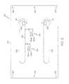
- Figure 2 is a top view of an example of a magnetic flux sensor plate 124 or laminate in accordance with an embodiment of the present disclosure.
- Each sensor plate 124 of the flux sensor core portion 122 may include a first pair of sensor holes 128a and 128b and a second pair of sensor holes 130a and 130b for use in sensing a level of the magnetic flux flow 116 at a respective location of each of the first pair of sensor holes 128a and 128b and the second pair of sensor holes 130a and 130b.
- the first pair of sensor holes 128 and second pair of sensor holes 130 may be disposed along one longitudinal side or side with the longest dimension of the elongated opening 104.
- the first pair of sensor holes 128a and 128b may be a distance "D1" from an edge 132 of the opening 104 to the sensor hole 128b farthest from an edge 132 of the opening 104.
- the second pair of sensor holes 130a and 130b may be a distance "D2" from the edge 132 of the opening 104 to the sensor hole 130b farthest from the edge.
- the spacing between the sensor holes of each pair may be about half the distance "D1.”
- the pairs of sensor holes 128 and 130 are positioned relative to the opening 104 through the magnetic flux core 102 for use in sensing the level of the magnetic flux flow 116 at different distances from the opening 104 while minimizing disruption of the magnetic flux flow 116 in the flux sensor core portion 122 of the magnetic flux core 102.
- a first sensor conductor winding 134 ( Figure 1 ) extends through the first pair of sensor holes 128a and 128b and connects to a core flux sensor device 136.
- a second sensor conductor winding 138 extends through the second pair of sensor holes 130a and 130b and connects to the core flux sensor device 136.
- the sensor holes 128 and 130 may be substantially elongate as illustrated in Figure 2 for receiving the sensor windings 134 and 138 or the sensor holes 128 and 130 may be some other shape and size for receiving a particular shape and size of the sensor windings 134 and 138.
- the magnetic flux flow 116 generates an electrical signal in each of the sensor conductor winding 134 and 138.
- An amplitude of the electrical signal in each sensor conductor winding 134 and 138 corresponds to the level of the magnetic flux flow at the respective location of each sensor conductor winding 134 and 138 or sensor holes 128 and 130.
- the core flux sensor device 136 may be an oscilloscope or other device for detecting the magnetic flux flow and measuring the level of the magnetic flux flow in the core 102 at the respective location of the sensor holes 128 and 130 and sensor windings 134 and 138.
- the sensor windings 134 and 138 define loop antenna sensors as described in more detail below.
- the core flux sensor arrangement 120 may include the sensor holes 128, 130, the sensor windings 134 and 138 through the sensor holes 128 and 130 and the core flux sensor device 136.
- While the exemplary electromagnetic device 100 illustrated in Figure 1 has been described as having two pairs of sensor holes 128 and 130, other embodiments may have a single pair of sensor holes and a single sensor winding or more than two pairs of sensor holes and sensor windings for use in detecting or measuring a magnetic flux level at different locations in a magnetic flux core.
- the sensor plates 124 may be made from a material capable of absorbing a magnetic flux.
- the plates 124 may be made from silicon steel alloy, a nickel-iron alloy or other metallic material capable of absorbing a magnetic flux similar to that described herein.
- the core 102 may be a nickel-iron alloy including about 20% by weight iron and about 80% by weight nickel.
- the plates 124 may be substantially square or rectangular, or may be some other geometric shape depending on the application of the electromagnetic device 100 and the environment where the electromagnetic device may be located.
- each sensor hole may be positioned relative to the at least one elongated opening 104 for preventing significant disruption of the magnetic flux flow in the sensor core portion 102 and for use in sensing the magnetic flux flow at different distances from the edge 132 of the at least one elongated opening 104.
- the sensor conductor winding may be a single wire or antenna element in each single sensor hole.
- the single sensor holes may be substantially circular or round or may be shaped to accommodate a size and shape of the single wire or antenna element.
- Holes 140 may be formed in each of the flux sensor core plates 124 for receiving a fastener for assembling a plurality of sensor core plates 124 together in a stack as illustrated in Figure 1 .
- the electromagnetic device 100 may also include a spacer portion 142 and 144 disposed on each outside flux sensor core plate 124.
- Each spacer portion 142 and 144 may include a plurality of spacer plates 146 stacked on one another.
- the spacer plates 146 may be made from a non-magnetic material or material that is an electrical insulator or dielectric.
- Figure 3 is a top view of an example of a spacer plate 146 or laminate in accordance with an embodiment of the present disclosure.
- the spacer plate 146 may be substantially "E" shaped as illustrated in Figure 3 .
- the spacer plate 146 may include a main segment 302, a center segment 304 extending from a central portion of the main member 302 and two outer segments 306 and 308 extending from opposite ends of the main segment 302.
- a plurality of spacer plates 146 stacked to form the spacer portions 142 and 144 provide openings 310 and 312 formed between the two outer segments 306 and 308 and the center segment 304 as in the embodiment illustrated in Figure 3 .
- the primary conductor windings 108 and secondary conductor windings 110 pass or extend through the openings 310 and 312.
- Each spacer plate 146 may also include a gap or gaps 314 and 316 for the sensor conductor windings 134 and 138 that pass through each pair of sensor holes 128 and 130 ( Figures 1 and 2 ) to connect to the core flux sensor device 136 for detecting the magnetic flux level at the location of each sensor conductor winding 134 and 138 and associated pair of sensor holes 128 and 130.
- Each spacer plate 146 may also include holes 318 which will align with holes 140 in the flux sensor core plates 124 to receive holding devices or fasteners for holding the components of the electromagnetic device 100 together.
- the electromagnetic device 100 also includes a magnetic core portions 148 and 150 respectively disposed on each spacer portion 142 and 144.
- the elongated openings 104 and 106 extend through each magnetic core portion 148 and 150 and the primary and secondary conductor windings 108 and 110 extend or pass through each magnetic core portion 148 and 150.
- Each magnetic core portion 148 and 150 may include a plurality of magnetic core plates 152 or laminates stacked on one another as illustrated in the exemplary embodiment in Figure 1 .
- the plates 152 may be made from the same material as the sensor plates 124 that are capable of absorbing a magnetic flux as described herein.
- Figure 4 is a top view of an example of a magnetic core plate 152 or laminate in accordance with an embodiment of the present disclosure.
- the magnetic core plate 152 includes a first elongated opening 402 which corresponds to opening 104 in Figure 1 and a second elongated opening 404 which corresponds to opening 106.
- the second elongated opening 404 may be parallel to the first elongated opening 402 to permit the conductor winding or windings 108 and 110 to pass through the stacked magnetic core plates 152 forming the magnetic core portions 148 and 150.
- the openings 402 and 404 in each magnetic core plate 152 respectively form the openings 104 and 106 when the magnetic core plates or laminates are stacked together to form the magnetic core portions 148 and 150.
- Each magnetic core plate 152 may also include a plurality of holes 406 which align with the openings 318 in the spacer plates 146 and openings 140 in the flux sensor core plates 124 for receiving a fastener or the like for assembling the magnetic flux core 102 of the electromagnetic device 100 ( Figure 1 ).
- the core flux control system 101 may include a core flux control device 154.
- the core flux control device 154 may be configured to adjust the electrical current flowing through the primary conductor winding 108 to control the magnetic flux level in the magnetic flux core 102 of the electromagnetic device 100.
- the core flux control device 154 may be coupled to the primary winding 108 and may receive control input signals corresponding to the magnetic flux level from the core flux sensor device 136.
- the core flux control device 154 may adjust the electrical current flowing through the primary conductor winding 108 in response to the magnetic flux level detected or measured by the core flux sensor device 136.
- the core flux control device 154 may be adapted to adjust a number of turns in the primary conductor winding 108 so that a predetermined magnetic flux level may be maintained in the magnetic flux core 102.
- the core flux control system 101 may include an additional winding or a control winding 156 or windings through the openings 104 and 106 of the magnetic core 102.
- the control winding 156 is coupled to the core flux control device 154.
- the core flux control device 154 may be adapted to connect the electrical power source 112 to the control winding 156 or windings and thereby adjust the number of turns of the primary winding 108.
- the core flux control device 154 in addition to being able to switch in or out the additional primary winding or control winding 156, may also control the amplitude or amount of current flowing in the control winding 156 to control the level of magnetic flux flow in the core 102.
- the core flux sensor arrangement 120 may detect the magnetic flux level in the magnetic flux core 102 when a peak source current is flowing through the primary conductor winding 108.
- the core flux control device 154 may be adapted to increase the electrical current flow through the primary conductor winding 108 and/or control winding 156 in response to the magnetic flux level being lower than a predetermined level for the peak source current and to reduce the electrical current flowing through the primary conductor winding 108 and/or control winding 156 in response to the level of the magnetic flux flow being higher than the predetermined level for the peak current.
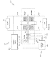
- FIG 5 is a block schematic diagram of the exemplary electromagnetic device 100 and the core flux control system 101 of Figure 1 .
- the core flux sensor device 136 detects the magnetic flux flow in the magnetic flux core 102 of the electromagnetic device 100 and measures a level of the magnetic flux flow in the magnetic flux core 102.
- the core flux sensor device 136 provides a signal corresponding to the magnetic flux level to the core flux control device 154.
- the core flux control device 154 is configured to adjust the electrical current flowing through the primary conductor winding 108 or windings to control the magnetic flux level in the magnetic flux core 102.
- the core flux control device 154 may be adapted to adjust a number of turns in the conductor winding by adding or subtracting turns to maintain a predetermined magnetic flux level in the magnetic flux core 102.
- the core flux sensor 136 may detect the magnetic flux level in the magnetic flux core 102 when a peak source current is flowing through the primary conductor winding 108.
- the core flux control device 154 may increase the electrical current flow or increase an amplitude of the electrical current flowing through the primary conductor winding 108 in response to the magnetic flux level being lower than the predetermined level for the peak source current, and the core flux control device 154 may reduce the electrical current or reduce an amplitude of the current flowing through the conductor winding 108 in response to the level of the magnetic flux flow being higher than the predetermined level for the peak current.
- the core flux control device 154 may also be connected to an additional winding or control winding 156 or windings. In addition to controlling the amount or amplitude of current flowing in the primary conductor winding 108, the core flux control device 154 may also switch in or out the control winding 156 and may increase or decrease electrical current flowing in the control winding 156 to further control the magnetic flux level in the core 102.
- Figure 6 is a flow chart of an example of a method 600 for controlling magnetic flux in an electromagnetic device for power management in accordance with an embodiment of the present disclosure.
- the method of 600 may be performed by the electromagnetic device 100 and the core flux control system 101 of Figure 1 or a similar system.
- a magnetic flux flow in a magnetic flux core may be detected and a level of the magnetic flux flow in the core measured.
- a core flux sensor arrangement may detect the magnetic flux flow and level in the magnetic flux core.
- At least one pair of sensor holes may be formed in at least a portion of the magnetic core similar to that previously described and a sensor conductor winding may be passed through the at least one pair of sensor holes forming a loop sensor antenna for detecting the magnetic flux flow and level.
- the magnetic flux flow causes an electrical signal to be generated in the sensor conductor winding or loop antenna. An amplitude of the electrical signal corresponds to the magnetic flux level in the magnetic flux core.
- an electrical current flowing through a conductor winding passing through the magnetic flux core may be adjusted in response to the magnetic flux level detected or measured to control the magnetic flux level in the core.
- electrical current in a control winding may be adjusted in response to the magnetic flux level detected or measured in the core to control the flux flow level in the core by increasing or decreasing the current.
- the magnetic flux level may also be controlled or adjusted by adjusting the number of turns of the primary winding to maintain a predetermined magnetic flux level.
- electrical current flowing in a primary conductor winding or a control winding or both may be increased in response to the magnetic flux level being lower than a predetermined level for a peak source current.
- electrical current flowing in a primary conductor winding or a control winding or both may be reduced in response to the magnetic flux level being higher than the predetermined level or the peak source current.
Landscapes
- Engineering & Computer Science (AREA)
- Power Engineering (AREA)
- Physics & Mathematics (AREA)
- General Physics & Mathematics (AREA)
- Electromagnetism (AREA)
- Radar, Positioning & Navigation (AREA)
- Automation & Control Theory (AREA)
- Condensed Matter Physics & Semiconductors (AREA)
- Measuring Instrument Details And Bridges, And Automatic Balancing Devices (AREA)
- Measuring Magnetic Variables (AREA)
- Transformers For Measuring Instruments (AREA)
Abstract
Description
- The present disclosure relates to electromagnetic devices, such as electrical transformers and inductors, and more particularly to controlling the magnetic flux in a core of an electromagnetic device for power management.
- Electromagnetic devices, such as inductors, transformers and similar devices include magnetic cores in which a magnetic flux flow may be generated in response to an electrical current flowing through a conductor winding associated with the magnetic core. As current (AC) in the magnetic core increases, the inductance in the core increases (energy storage in the device increases). In a transformer configuration which includes a primary winding connected to an electrical power source and a secondary winding connected to a load, changes in the current or voltage supplied by the electrical power source can significantly change the energy being stored in the magnetic core for transfer into the secondary. For example a lightning strike on the primary winding of the transformer can result in extremely high voltage and current levels transferred to the secondary which may potentially damaging to the load. Accordingly, there is a need to control a level of magnetic flux flow in the cores of transformers and other electromagnetic devices.
- In accordance with an embodiment, an electromagnetic device may include a magnetic flux core and an opening through the magnetic flux core. A conductor winding is received in the opening and extends through the magnetic flux core. An electrical current flowing through the conductor winding generates a magnetic field about the conductor winding and a magnetic flux flow about the opening in the magnetic flux core. The electromagnetic device may also include a core flux sensor arrangement to detect a magnetic flux level in the magnetic flux core. The electromagnetic device may additionally include a core flux control system configured to adjust the electrical current flowing through the conductor winding to control the magnetic flux level in the magnetic flux core.
- In accordance with another embodiment, an electromagnetic device may include a flux sensor core portion and at least one elongated opening through the flux sensor core portion. A conductor winding may be received in the at least one elongated opening and extend through the flux sensor core portion. An electrical current flowing through the conductor winding generates a magnetic field about the conductor winding and a magnetic flux flow about the at least one elongated opening in the flux sensor core portion. A plurality of pairs of sensor holes may be positioned relative to the at least one elongated opening for preventing significant disruption of the magnetic flux flow in the sensor core portion and for use in sensing a magnetic flux level at different distances from an edge of the at least one elongated opening. The electromagnetic device may also include a sensor conductor winding through each pair of sensor holes. The magnetic flux flow generates an electrical signal in each sensor conductor winding. The electrical signal in a particular sensor conductor winding corresponds to the magnetic flux level at a location of the particular sensor conductor winding. The electromagnetic device may additionally include a core flux sensor for detecting the magnetic flux level at the location of each sensor conductor winding. A spacer portion may be disposed on opposite sides of the flux sensor core. The spacer portion may include an opening and the conductor winding may pass through the spacer portion opening. A magnetic core portion may be disposed on each spacer portion. The at least one elongated opening extends through the magnetic core portion and the conductor winding extends through each magnetic core portion. The spacer portion may include a gap for the sensor conductor winding through each pair of sensor holes to connect to the core flux sensor for detecting the magnetic flux level at the location of each sensor conductor winding. The electromagnetic device may further include a core flux control system configured to adjust the electrical current flowing through the conductor winding to control the magnetic flux level in the magnetic flux core.
- In accordance with further embodiment, a method for controlling a magnetic flux level of an electromagnetic device may include detecting a magnetic flux level in a magnetic flux core of the electromagnetic device. The method may also include adjusting an electrical source current flowing through a conductor winding that extends through an opening through the magnetic flux core of the electromagnetic device to control the magnetic flux level in the core. An amount or amplitude of electrical source current flowing through the conductor winding corresponds to the magnetic flux level.
- The following detailed description of embodiments refers to the accompanying drawings, which illustrate specific embodiments of the disclosure. Other embodiments having different structures and operations do not depart from the scope of the present disclosure.
-
Figure 1 is a side cross-sectional view of an example of an electromagnetic device and a core flux control system in accordance with an embodiment of the present disclosure. -
Figure 2 is a top view of an example of a magnetic flux sensor plate or laminate in accordance with an embodiment of the present disclosure. -
Figure 3 is a top view of an example of a spacer plate or laminate in accordance with an embodiment of the present discloser. -
Figure 4 is a top view of an example of a magnetic core plate or laminate in accordance with an embodiment of the present disclosure. -
Figure 5 is a block schematic diagram of the exemplary electromagnetic device and the core flux control system ofFigure 1 . -
Figure 6 is a flow chart of an example of a method for controlling magnetic flux in an electromagnetic device for power management in accordance with an embodiment of the present disclosure. - The following detailed description of embodiments refers to the accompanying drawings, which illustrate specific embodiments of the disclosure. Other embodiments having different structures and operations do not depart from the scope of the present disclosure. Like reference numerals may refer to the same element or component in the different drawings.
- In accordance with an embodiment of the present disclosure, a linear inductor is an electromagnetic device having only one electrical conductor wire winding or windings passing through a magnetic core. In accordance with another embodiment, a linear transformer is an electromagnetic device where a linear primary electrical conductor wire winding or windings and one or more linear secondary electrical conductor wire winding or windings pass through a magnetic core. The core may be one piece and no turns of the primary and secondary electrical conductors about the core are required. While the core may be one piece, the one piece core may be formed from a plurality of stacked plates or laminates. A current may be conducted through the primary. A magnetic flux from the current in the primary is absorbed by the core. When the current in the primary decreases the core transmits an electromotive force (desorbs) into the secondary wires. A feature of the linear transformer is the linear pass of the primary and secondary conductors through the core. One core may be used as a standalone device or a series of two or more cores may be used where a longer linear exposure is required. Another feature of this transformer is that the entire magnetic field or at least a substantial portion of the magnetic field generated by the current in the primary is absorbed by the core, and desorbed into the secondary. The core of the transformer may be sized or include dimensions so that substantially the entire magnetic field generated by the current is absorbed by the core and so that the magnetic flux is substantially completely contained with the core. This forms a highly efficient transformer with very low copper losses, high efficiency energy transfer, low thermal emission and very low radiated emissions. Additionally the linear transformer is a minimum of about 50% lower in volume and weight then existing configurations. Linear electromagnetic devices, such as linear transformers, inductors and similar devices are described in more detail in
EP 2 688 076 A2 , entitled "Linear Electromagnetic Device" which is assigned to the same applicant as the present application and is comprised in the state of the art under Article 54(3) EPC. A magnetic core flux sensor assembly is described in more detail inU.S. Patent Application No. 13/773,135, filed 02/21/2013 -
Figure 1 is a cross-sectional view of an example of anelectromagnetic device 100 and coreflux control system 101 in accordance with an embodiment of the present disclosure. Theelectromagnetic device 100 may include amagnetic flux core 102. As described in more detail herein, the coreflux control system 101 may be configured to adjust an electrical current flowing through a conductor winding to control a magnetic flux level in themagnetic flux core 102. Afirst opening 104 and asecond opening 106 may be formed through themagnetic core 102. The first opening 104 and thesecond opening 106 may be elongated openings similar to that illustrated inFigures 2 and4 . The exemplaryelectromagnetic device 100 illustrated inFigure 1 may be configured as a transformer and may include a primary conductor winding 108 and a secondary conductor winding 110. The primary conductor winding 108 may extend through thefirst opening 104 and thesecond opening 106 and may be coupled to asource 112 of electrical power. Thesource 112 may be a voltage generator. The secondary conductor winding 110 may also extend through thefirst opening 104 and thesecond opening 106 and maybe coupled to aload 114. Theload 114 may be a variable load. An electrical current flowing through the primary conductor winding 108 generates a magnetic field around the primary conductor winding 108 and a magnetic flux flow is created in themagnetic core 102 as illustrated byarrows Figures 2 and4 . The magnetic flux flow in themagnetic core 102 will be in opposite directions about the respectiveelongated openings arrows Figure 1 ) through theelongated openings Figure 2 inwindings 108 throughelongated opening 104 will cause a magnetic flux flow in the direction ofarrow 116 in the example inFigure 2 , and electric current flowing out of the page in thesame windings 108 throughelongated opening 106 will cause a magnetic flux flow in the direction ofarrow 118. - While the exemplary
electromagnetic device 100 illustrated inFigure 1 has been described as having afirst opening 104 and asecond opening 106 through themagnetic flux core 102 and primary andsecondary windings openings - The
electromagnetic device 100 may include a coreflux sensor arrangement 120 to detect a magnetic flux level in themagnetic flux core 102. Themagnetic flux core 102 of theelectromagnetic device 100 may include a fluxsensor core portion 122 that may be part of the coreflux sensor arrangement 120. The fluxsensor core portion 122 may include a plurality of fluxsensor core plates 124 or laminates that are stacked on one another. Referring also toFigure 2, Figure 2 is a top view of an example of a magneticflux sensor plate 124 or laminate in accordance with an embodiment of the present disclosure. Eachsensor plate 124 of the fluxsensor core portion 122 may include a first pair ofsensor holes sensor holes magnetic flux flow 116 at a respective location of each of the first pair ofsensor holes sensor holes sensor holes 128 and second pair of sensor holes 130 may be disposed along one longitudinal side or side with the longest dimension of theelongated opening 104. The first pair ofsensor holes edge 132 of theopening 104 to thesensor hole 128b farthest from anedge 132 of theopening 104. The second pair ofsensor holes edge 132 of theopening 104 to thesensor hole 130b farthest from the edge. The spacing between the sensor holes of each pair may be about half the distance "D1." The pairs ofsensor holes opening 104 through themagnetic flux core 102 for use in sensing the level of themagnetic flux flow 116 at different distances from theopening 104 while minimizing disruption of themagnetic flux flow 116 in the fluxsensor core portion 122 of themagnetic flux core 102. - A first sensor conductor winding 134 (
Figure 1 ) extends through the first pair ofsensor holes flux sensor device 136. A second sensor conductor winding 138 extends through the second pair ofsensor holes flux sensor device 136. The sensor holes 128 and 130 may be substantially elongate as illustrated inFigure 2 for receiving thesensor windings sensor windings magnetic flux flow 116 generates an electrical signal in each of the sensor conductor winding 134 and 138. An amplitude of the electrical signal in each sensor conductor winding 134 and 138 corresponds to the level of the magnetic flux flow at the respective location of each sensor conductor winding 134 and 138 orsensor holes flux sensor device 136 may be an oscilloscope or other device for detecting the magnetic flux flow and measuring the level of the magnetic flux flow in thecore 102 at the respective location of the sensor holes 128 and 130 andsensor windings sensor windings flux sensor arrangement 120 may include the sensor holes 128, 130, thesensor windings flux sensor device 136. - While the exemplary
electromagnetic device 100 illustrated inFigure 1 has been described as having two pairs ofsensor holes - The
sensor plates 124 may be made from a material capable of absorbing a magnetic flux. For example, theplates 124 may be made from silicon steel alloy, a nickel-iron alloy or other metallic material capable of absorbing a magnetic flux similar to that described herein. In an embodiment, thecore 102 may be a nickel-iron alloy including about 20% by weight iron and about 80% by weight nickel. Theplates 124 may be substantially square or rectangular, or may be some other geometric shape depending on the application of theelectromagnetic device 100 and the environment where the electromagnetic device may be located. - In accordance with another embodiment, rather than a plurality of pairs of
sensor holes elongated opening 104 for preventing significant disruption of the magnetic flux flow in thesensor core portion 102 and for use in sensing the magnetic flux flow at different distances from theedge 132 of the at least oneelongated opening 104. The sensor conductor winding may be a single wire or antenna element in each single sensor hole. The single sensor holes may be substantially circular or round or may be shaped to accommodate a size and shape of the single wire or antenna element. -
Holes 140 may be formed in each of the fluxsensor core plates 124 for receiving a fastener for assembling a plurality ofsensor core plates 124 together in a stack as illustrated inFigure 1 . - The
electromagnetic device 100 may also include aspacer portion sensor core plate 124. Eachspacer portion spacer plates 146 stacked on one another. Thespacer plates 146 may be made from a non-magnetic material or material that is an electrical insulator or dielectric. Referring also toFigure 3, Figure 3 is a top view of an example of aspacer plate 146 or laminate in accordance with an embodiment of the present disclosure. Thespacer plate 146 may be substantially "E" shaped as illustrated inFigure 3 . Thespacer plate 146 may include amain segment 302, acenter segment 304 extending from a central portion of themain member 302 and twoouter segments main segment 302. A plurality ofspacer plates 146 stacked to form thespacer portions openings outer segments center segment 304 as in the embodiment illustrated inFigure 3 .
Theprimary conductor windings 108 andsecondary conductor windings 110 pass or extend through theopenings - Each
spacer plate 146 may also include a gap orgaps sensor conductor windings sensor holes 128 and 130 (Figures 1 and2 ) to connect to the coreflux sensor device 136 for detecting the magnetic flux level at the location of each sensor conductor winding 134 and 138 and associated pair ofsensor holes spacer plate 146 may also includeholes 318 which will align withholes 140 in the fluxsensor core plates 124 to receive holding devices or fasteners for holding the components of theelectromagnetic device 100 together. - The
electromagnetic device 100 also includes amagnetic core portions spacer portion elongated openings magnetic core portion secondary conductor windings magnetic core portion - Each
magnetic core portion magnetic core plates 152 or laminates stacked on one another as illustrated in the exemplary embodiment inFigure 1 . Theplates 152 may be made from the same material as thesensor plates 124 that are capable of absorbing a magnetic flux as described herein. Referring also toFigure 4, Figure 4 is a top view of an example of amagnetic core plate 152 or laminate in accordance with an embodiment of the present disclosure. Themagnetic core plate 152 includes a firstelongated opening 402 which corresponds to opening 104 inFigure 1 and a secondelongated opening 404 which corresponds toopening 106. The secondelongated opening 404 may be parallel to the firstelongated opening 402 to permit the conductor winding orwindings magnetic core plates 152 forming themagnetic core portions openings magnetic core plate 152 respectively form theopenings magnetic core portions - Each
magnetic core plate 152 may also include a plurality ofholes 406 which align with theopenings 318 in thespacer plates 146 andopenings 140 in the fluxsensor core plates 124 for receiving a fastener or the like for assembling themagnetic flux core 102 of the electromagnetic device 100 (Figure 1 ). - The core flux control system 101 (
Figure 1 ) may include a coreflux control device 154. The coreflux control device 154 may be configured to adjust the electrical current flowing through the primary conductor winding 108 to control the magnetic flux level in themagnetic flux core 102 of theelectromagnetic device 100. The coreflux control device 154 may be coupled to the primary winding 108 and may receive control input signals corresponding to the magnetic flux level from the coreflux sensor device 136. The coreflux control device 154 may adjust the electrical current flowing through the primary conductor winding 108 in response to the magnetic flux level detected or measured by the coreflux sensor device 136. The coreflux control device 154 may be adapted to adjust a number of turns in the primary conductor winding 108 so that a predetermined magnetic flux level may be maintained in themagnetic flux core 102. In accordance with an embodiment, the coreflux control system 101 may include an additional winding or a control winding 156 or windings through theopenings magnetic core 102. The control winding 156 is coupled to the coreflux control device 154. The coreflux control device 154 may be adapted to connect theelectrical power source 112 to the control winding 156 or windings and thereby adjust the number of turns of the primary winding 108. The coreflux control device 154 in addition to being able to switch in or out the additional primary winding or control winding 156, may also control the amplitude or amount of current flowing in the control winding 156 to control the level of magnetic flux flow in thecore 102. - The core
flux sensor arrangement 120 may detect the magnetic flux level in themagnetic flux core 102 when a peak source current is flowing through the primary conductor winding 108. The coreflux control device 154 may be adapted to increase the electrical current flow through the primary conductor winding 108 and/or control winding 156 in response to the magnetic flux level being lower than a predetermined level for the peak source current and to reduce the electrical current flowing through the primary conductor winding 108 and/or control winding 156 in response to the level of the magnetic flux flow being higher than the predetermined level for the peak current. -
Figure 5 is a block schematic diagram of the exemplaryelectromagnetic device 100 and the coreflux control system 101 ofFigure 1 . As previously discussed, the coreflux sensor device 136 detects the magnetic flux flow in themagnetic flux core 102 of theelectromagnetic device 100 and measures a level of the magnetic flux flow in themagnetic flux core 102. The coreflux sensor device 136 provides a signal corresponding to the magnetic flux level to the coreflux control device 154. The coreflux control device 154 is configured to adjust the electrical current flowing through the primary conductor winding 108 or windings to control the magnetic flux level in themagnetic flux core 102. The coreflux control device 154 may be adapted to adjust a number of turns in the conductor winding by adding or subtracting turns to maintain a predetermined magnetic flux level in themagnetic flux core 102. For example, thecore flux sensor 136 may detect the magnetic flux level in themagnetic flux core 102 when a peak source current is flowing through the primary conductor winding 108. The coreflux control device 154 may increase the electrical current flow or increase an amplitude of the electrical current flowing through the primary conductor winding 108 in response to the magnetic flux level being lower than the predetermined level for the peak source current, and the coreflux control device 154 may reduce the electrical current or reduce an amplitude of the current flowing through the conductor winding 108 in response to the level of the magnetic flux flow being higher than the predetermined level for the peak current. - As previously discussed, the core
flux control device 154 may also be connected to an additional winding or control winding 156 or windings. In addition to controlling the amount or amplitude of current flowing in the primary conductor winding 108, the coreflux control device 154 may also switch in or out the control winding 156 and may increase or decrease electrical current flowing in the control winding 156 to further control the magnetic flux level in thecore 102. -
Figure 6 is a flow chart of an example of amethod 600 for controlling magnetic flux in an electromagnetic device for power management in accordance with an embodiment of the present disclosure. The method of 600 may be performed by theelectromagnetic device 100 and the coreflux control system 101 ofFigure 1 or a similar system. Inblock 602, a magnetic flux flow in a magnetic flux core may be detected and a level of the magnetic flux flow in the core measured. As previously described, a core flux sensor arrangement may detect the magnetic flux flow and level in the magnetic flux core. At least one pair of sensor holes may be formed in at least a portion of the magnetic core similar to that previously described and a sensor conductor winding may be passed through the at least one pair of sensor holes forming a loop sensor antenna for detecting the magnetic flux flow and level. The magnetic flux flow causes an electrical signal to be generated in the sensor conductor winding or loop antenna. An amplitude of the electrical signal corresponds to the magnetic flux level in the magnetic flux core. - In
block 604, an electrical current flowing through a conductor winding passing through the magnetic flux core may be adjusted in response to the magnetic flux level detected or measured to control the magnetic flux level in the core. Alternatively or in addition, electrical current in a control winding may be adjusted in response to the magnetic flux level detected or measured in the core to control the flux flow level in the core by increasing or decreasing the current. The magnetic flux level may also be controlled or adjusted by adjusting the number of turns of the primary winding to maintain a predetermined magnetic flux level. - In
block 606, electrical current flowing in a primary conductor winding or a control winding or both may be increased in response to the magnetic flux level being lower than a predetermined level for a peak source current. - In
block 608, electrical current flowing in a primary conductor winding or a control winding or both may be reduced in response to the magnetic flux level being higher than the predetermined level or the peak source current. - The terminology used herein is for the purpose of describing particular embodiments only and is not intended to be limiting of the disclosure. As used herein, the singular forms "a", "an" and "the" are intended to include the plural forms as well, unless the context clearly indicates otherwise. It will be further understood that the terms "comprises" and/or "comprising," when used in this specification, specify the presence of stated features, integers, steps, operations, elements, and/or components, but do not preclude the presence or addition of one or more other features, integers, steps, operations, elements, components, and/or groups thereof.
- Although specific embodiments have been illustrated and described herein, those of ordinary skill in the art appreciate that any arrangement which is calculated to achieve the same purpose may be substituted for the specific embodiments shown and that the embodiments herein have other applications in other environments. This application is intended to cover any adaptations or variations of the present disclosure. The following claims are in no way intended to limit the scope of the disclosure to the specific embodiments described herein.
Claims (15)
- An electromagnetic device, comprising:a magnetic flux core;an opening through the magnetic flux core;a conductor winding received in the opening and extending through the magnetic flux core, wherein an electrical current flowing through the conductor winding generates a magnetic field about the conductor winding and a magnetic flux flow about the opening in the magnetic flux core;a core flux sensor arrangement to detect a magnetic flux level in the magnetic flux core; anda core flux control system configured to adjust the electrical current flowing through the conductor winding to control the magnetic flux level in the magnetic flux core.
- The electromagnetic device of claim 1, wherein the core flux sensor arrangement comprises:a pair of sensor holes formed through at least a portion of the magnetic flux core, the pair of sensor holes being positioned relative to the opening through the magnetic flux core for use in sensing the magnetic flux flow while minimizing disruption of the magnetic flux flow in the magnetic flux core; anda sensor conductor winding through the pair of sensor holes, the magnetic flux flow generating a first electrical signal in the sensor conductor winding, the first electrical signal in the sensor conductor winding corresponding to the magnetic flux level at a location of the sensor conductor winding.
- The electromagnetic device of claim 2, wherein the core flux sensor arrangement comprises:a second pair of sensor holes formed through at least the portion of the magnetic flux core at a greater distance from the opening than the pair of sensor holes, the second pair of sensor holes for use in sensing the magnetic flux flow at a location of the second pair of sensor holes; anda second sensor conductor winding through the second pair of sensor holes, the magnetic flux flow generating a second electrical signal in the second sensor conductor winding, the second electrical signal in the second sensor conductor winding corresponding to the magnetic flux level at the location of the second sensor conductor winding.
- The electromagnetic device of any one of claims 1-3, wherein the opening through the magnetic flux core is an elongated opening for receiving at least the conductor winding and
further comprising:a second elongated opening; anda secondary conductor winding, wherein the core flux control system adjusts the electrical current flowing through the conductor winding to control the magnetic flux level in the core and a power output of the secondary conductor winding based on the magnetic flux level in the core. - The electromagnetic device of any one of claims 1-4, wherein the core flux control system is adapted to adjust a number of turns in the conductor winding to maintain a predetermined magnetic flux level in the magnetic flux core.
- The electromagnetic device of any one of claims 1-5, wherein the core flux sensor arrangement detects the magnetic flux level in the magnetic flux core when a peak source current is flowing through the conductor winding, the core flux control system being adapted to increase the electrical current flowing through the conductor winding in response to the magnetic flux level being lower than a predetermined level for the peak source current and to reduce the electrical current flowing through the conductor winding in response to the magnetic flux flow being higher than the predetermined level for the peak current.
- The electromagnetic device of any one of claims 1-6, further comprising a control winding through at least a portion of the core, wherein the core flux control system increases or decreases electrical current flowing in the control winding to control the magnetic flux level in the core.
- The electromagnetic device of claim 7 wherein the core flux sensor arrangement detects the magnetic flux level in the magnetic flux core when a peak source current is flowing through the conductor winding, the core flux control system being adapted to increase the electrical current flowing through the control winding in response to the magnetic flux level being lower than a predetermined level for the peak source current and to reduce the electrical current flowing through the control winding in response to the magnetic flux flow being higher than the predetermined level for the peak current.
- The electromagnetic device of any one of claims 1-8, further comprising a spacer portion disposed on opposite sides of the flux sensor core portion, wherein the spacer portion comprises an opening and the conductor winding passes through the spacer portion opening.
- The electromagnetic device of claim 9, wherein:a magnetic core portion of the magnetic flux core is disposed on each spacer portion;the at least one elongated opening extends through the magnetic core portion; andthe conductor winding extends through each magnetic core portion.
- The electromagnetic device of claim 10 wherein the spacer portion comprises a gap for the sensor conductor winding through each pair of sensor holes to connect to the core flux sensor for detecting the magnetic flux flow at the location of each sensor conductor winding.
- A method for controlling a magnetic flux flow in an electromagnetic device, comprising:detecting a magnetic flux level in a magnetic flux core of the electromagnetic device; andadjusting an electrical source current flowing through a conductor winding extending through an opening in the magnetic flux core of the electromagnetic device to control the magnetic flux level in the magnetic flux core, an amplitude of the electrical source current flowing through the conductor winding corresponding to the magnetic flux level.
- The method of claim 12, further comprising adjusting a number of turns in the conductor winding to adjust the electrical source current and maintain a predetermined magnetic flux level in the magnetic flux core.
- The method claim 12 or 13, further comprising:detecting the magnetic flux core when a peak source current is flowing through the conductor winding;increasing the electrical current flowing through the conductor winding in response to the magnetic flux level being lower than a predetermined level for the peak source current; andreducing the electrical current flowing through the conductor winding in response to the magnetic flux level being higher than the predetermined level for the peak source current.
- The method of any one of claims 12-14, further comprising:increasing the amount of electrical current flowing in a control winding in response to the magnetic flux level being lower than a predetermined level for a peak source current flowing through the conductor winding; andreducing the amount of electrical current flowing in the control winding in response to the magnetic flux level being higher than the predetermined level for the peak source current flowing through the conductor winding.
Applications Claiming Priority (1)
| Application Number | Priority Date | Filing Date | Title |
|---|---|---|---|
| US13/953,314 US9389619B2 (en) | 2013-07-29 | 2013-07-29 | Transformer core flux control for power management |
Publications (2)
| Publication Number | Publication Date |
|---|---|
| EP2838093A1 true EP2838093A1 (en) | 2015-02-18 |
| EP2838093B1 EP2838093B1 (en) | 2019-11-27 |
Family
ID=51224848
Family Applications (1)
| Application Number | Title | Priority Date | Filing Date |
|---|---|---|---|
| EP14178702.8A Active EP2838093B1 (en) | 2013-07-29 | 2014-07-28 | Transformer core flux control for power management |
Country Status (3)
| Country | Link |
|---|---|
| US (1) | US9389619B2 (en) |
| EP (1) | EP2838093B1 (en) |
| JP (1) | JP6494941B2 (en) |
Cited By (1)
| Publication number | Priority date | Publication date | Assignee | Title |
|---|---|---|---|---|
| WO2018023176A1 (en) | 2016-08-05 | 2018-02-08 | Faraday Grid Limited | An electrical power supply system and process |
Families Citing this family (3)
| Publication number | Priority date | Publication date | Assignee | Title |
|---|---|---|---|---|
| CA3053095C (en) | 2016-02-12 | 2024-06-04 | Laki Power EHF. | Apparatus, system and method for power extraction |
| SE543181C2 (en) * | 2019-11-07 | 2020-10-20 | Invivopower Ab | Medical system comprising an implanted internal unit, an external unit, and method of initiating operation of external unit |
| EP4254446B1 (en) * | 2022-03-31 | 2025-08-27 | Hitachi Energy Ltd | Transformer dc magnetization detection and mitigation through vibration measurement |
Citations (7)
| Publication number | Priority date | Publication date | Assignee | Title |
|---|---|---|---|---|
| JPH01242333A (en) * | 1988-03-18 | 1989-09-27 | Nippon Steel Corp | Device for controlling number of steel plate of suspending electromagnetic |
| DE4129265A1 (en) * | 1991-08-30 | 1993-03-04 | Mannesmann Ag | ELECTROMAGNETIC SWITCHGEAR |
| JPH0977452A (en) * | 1995-09-11 | 1997-03-25 | Hitachi Kiden Kogyo Ltd | Crane automatic operation method using a lifting electromagnet |
| US20100194373A1 (en) * | 2007-06-12 | 2010-08-05 | Siemens Transformers Austria Gmbh & Co Kg | Electrical Transformer with Unidirectional Flux Compensation |
| US20130049751A1 (en) * | 2010-04-14 | 2013-02-28 | Peter Hamberger | Method and apparatus for detecting a magnetic characteristic variable in a core |
| EP2688076A2 (en) | 2012-07-19 | 2014-01-22 | The Boeing Company | Linear electromagnetic device |
| WO2014130122A1 (en) * | 2013-02-21 | 2014-08-28 | The Boeing Company | Magnetic core flux sensor |
Family Cites Families (47)
| Publication number | Priority date | Publication date | Assignee | Title |
|---|---|---|---|---|
| US352105A (en) | 1886-11-02 | op buda-pesth | ||
| US2411374A (en) | 1943-01-07 | 1946-11-19 | Westinghouse Electric Corp | Magnetic core structure for threephase transformers |
| US3042849A (en) | 1958-04-03 | 1962-07-03 | Ite Circuit Breaker Ltd | Saturable balancing reactors for rectifier systems |
| US3464002A (en) | 1967-09-28 | 1969-08-26 | Rudolf G Hentschel | Low q test coils for magnetic field sensing |
| US4338657A (en) | 1974-05-21 | 1982-07-06 | Lisin Vladimir N | High-voltage transformer-rectifier device |
| US4020440A (en) | 1975-11-25 | 1977-04-26 | Moerman Nathan A | Conversion and control of electrical energy by electromagnetic induction |
| DE2926423A1 (en) | 1979-06-27 | 1981-01-08 | Licentia Gmbh | VOLTAGE MEASURING DEVICE FOR VALVE CONTROL OF RECTIFIERS IN HGUE SYSTEMS |
| US4346340A (en) * | 1980-04-30 | 1982-08-24 | Hackett Jones Francis C | Method and means for controlling the flux density in the core of an inductor |
| US4684882A (en) | 1983-02-18 | 1987-08-04 | Blain Aurele J | Electrical transformer having a solid core surrounding winding in a loop configuration |
| GB2211671A (en) | 1987-10-28 | 1989-07-05 | Johan Christian Fitter | Electromagnetic devices with superconducting windings |
| JPH0745934Y2 (en) | 1991-02-20 | 1995-10-18 | 北川工業株式会社 | Noise absorber fixture |
| CA2100135C (en) * | 1992-07-10 | 1997-11-04 | Makoto Kawakami | Dc current sensor |
| DE69418127T2 (en) | 1993-10-04 | 1999-10-14 | Matsushita Electric Industrial Co. | Filter and two-mode resonator using stripline technology |
| US5534837A (en) | 1994-07-28 | 1996-07-09 | Rockwell International | Orthogonal-field electrically variable magnetic device |
| US5668707A (en) | 1994-10-04 | 1997-09-16 | Delco Electronics Corp. | Multi-phase power converter with harmonic neutralization |
| JPH10233316A (en) * | 1997-02-19 | 1998-09-02 | Hitachi Ltd | Polarization detecting element and transformer evaluation device for transformer |
| JP3518260B2 (en) * | 1997-07-18 | 2004-04-12 | 株式会社日立製作所 | Transformer, DC bias detection element of transformer, and DC bias evaluation device |
| US6380735B1 (en) | 1999-04-30 | 2002-04-30 | Sumitomo Special Metals Co., Ltd. | Orthogonal flux-gate type magnetic sensor |
| US6181079B1 (en) | 1999-12-20 | 2001-01-30 | Philips Electronics North America Corporation | High power electronic ballast with an integrated magnetic component |
| CA2435249A1 (en) | 2001-01-23 | 2002-08-01 | Harrie R. Buswell | Wire core inductive devices having a biassing magnet and methods of making the same |
| JP3523608B2 (en) * | 2001-04-03 | 2004-04-26 | 本田技研工業株式会社 | Magnetic flux detecting device and method |
| NO319424B1 (en) | 2001-11-21 | 2005-08-08 | Magtech As | Method for Controllable Conversion of a Primary AC / Voltage to a Secondary AC / Voltage |
| KR100464093B1 (en) | 2002-03-13 | 2005-01-03 | 삼성전기주식회사 | Fluxgate sensor integrated in print circuit board and method for manufacturing the same |
| KR100481552B1 (en) | 2002-07-30 | 2005-04-07 | 삼성전기주식회사 | Printed circuit board integrated 2-axis fluxgate sensor and method for manufacturing the same |
| US7109837B2 (en) | 2003-03-18 | 2006-09-19 | Pulse Engineering, Inc. | Controlled inductance device and method |
| US7362206B1 (en) | 2003-04-03 | 2008-04-22 | Edward Herbert | Variable transformer |
| US7573000B2 (en) | 2003-07-11 | 2009-08-11 | Lincoln Global, Inc. | Power source for plasma device |
| US7023313B2 (en) | 2003-07-16 | 2006-04-04 | Marvell World Trade Ltd. | Power inductor with reduced DC current saturation |
| JP4103713B2 (en) * | 2003-07-18 | 2008-06-18 | 株式会社デンソー | Current detector |
| US7378828B2 (en) | 2004-11-09 | 2008-05-27 | The Boeing Company | DC-DC converter having magnetic feedback |
| JP4294602B2 (en) | 2005-02-18 | 2009-07-15 | パナソニック株式会社 | Rotor magnetic pole position detecting device for multiphase motor, motor driving device including the same, and motor driving method |
| US7342477B2 (en) | 2005-07-01 | 2008-03-11 | The Boeing Company | Inductor |
| US20070145952A1 (en) | 2005-12-23 | 2007-06-28 | Cogeneration Energy Corp. | Efficient power system |
| US7449987B2 (en) | 2006-07-06 | 2008-11-11 | Harris Corporation | Transformer and associated method of making |
| US7639520B1 (en) | 2007-02-26 | 2009-12-29 | Network Appliance, Inc. | Efficient power supply |
| AT506454B1 (en) | 2008-02-22 | 2015-10-15 | Egston System Electronics Eggenburg Gmbh | CONVERTER ARRANGEMENT |
| US20090244937A1 (en) | 2008-03-28 | 2009-10-01 | American Superconductor Corporation | Dc bus voltage harmonics reduction |
| US8212505B2 (en) | 2008-12-02 | 2012-07-03 | GM Global Technology Operations LLC | Method and system for creating a vibration in an automobile |
| EP2460247A1 (en) | 2009-07-31 | 2012-06-06 | Gridmanager A/S | Method and apparatus for managing transmission of power in a power transmission network |
| EP2476132B1 (en) | 2009-09-07 | 2019-11-20 | ABB Schweiz AG | Method and system for power management |
| EP2333573B1 (en) | 2009-11-30 | 2012-10-24 | STMicroelectronics Srl | Integrated magnetic sensor for detecting horizontal magnetic fields and manufacturing process thereof |
| US9106125B1 (en) | 2010-06-28 | 2015-08-11 | The Boeing Company | Augmented power converter |
| US20120150679A1 (en) | 2012-02-16 | 2012-06-14 | Lazaris Spyros J | Energy management system for power transmission to an intelligent electricity grid from a multi-resource renewable energy installation |
| US8980053B2 (en) | 2012-03-30 | 2015-03-17 | Sabic Innovative Plastics Ip B.V. | Transformer paper and other non-conductive transformer components |
| US9455084B2 (en) | 2012-07-19 | 2016-09-27 | The Boeing Company | Variable core electromagnetic device |
| JP5783191B2 (en) * | 2013-02-01 | 2015-09-24 | 株式会社デンソー | Device for detecting bias, magnetic saturation, or magnetic flux |
| US9651633B2 (en) * | 2013-02-21 | 2017-05-16 | The Boeing Company | Magnetic core flux sensor |
-
2013
- 2013-07-29 US US13/953,314 patent/US9389619B2/en active Active
-
2014
- 2014-07-28 EP EP14178702.8A patent/EP2838093B1/en active Active
- 2014-07-29 JP JP2014153616A patent/JP6494941B2/en active Active
Patent Citations (7)
| Publication number | Priority date | Publication date | Assignee | Title |
|---|---|---|---|---|
| JPH01242333A (en) * | 1988-03-18 | 1989-09-27 | Nippon Steel Corp | Device for controlling number of steel plate of suspending electromagnetic |
| DE4129265A1 (en) * | 1991-08-30 | 1993-03-04 | Mannesmann Ag | ELECTROMAGNETIC SWITCHGEAR |
| JPH0977452A (en) * | 1995-09-11 | 1997-03-25 | Hitachi Kiden Kogyo Ltd | Crane automatic operation method using a lifting electromagnet |
| US20100194373A1 (en) * | 2007-06-12 | 2010-08-05 | Siemens Transformers Austria Gmbh & Co Kg | Electrical Transformer with Unidirectional Flux Compensation |
| US20130049751A1 (en) * | 2010-04-14 | 2013-02-28 | Peter Hamberger | Method and apparatus for detecting a magnetic characteristic variable in a core |
| EP2688076A2 (en) | 2012-07-19 | 2014-01-22 | The Boeing Company | Linear electromagnetic device |
| WO2014130122A1 (en) * | 2013-02-21 | 2014-08-28 | The Boeing Company | Magnetic core flux sensor |
Cited By (2)
| Publication number | Priority date | Publication date | Assignee | Title |
|---|---|---|---|---|
| WO2018023176A1 (en) | 2016-08-05 | 2018-02-08 | Faraday Grid Limited | An electrical power supply system and process |
| EP3494451B1 (en) * | 2016-08-05 | 2025-02-26 | Third Equation Ltd | An electrical power supply system and process |
Also Published As
| Publication number | Publication date |
|---|---|
| US20150028827A1 (en) | 2015-01-29 |
| JP2015038986A (en) | 2015-02-26 |
| EP2838093B1 (en) | 2019-11-27 |
| JP6494941B2 (en) | 2019-04-03 |
| US9389619B2 (en) | 2016-07-12 |
Similar Documents
| Publication | Publication Date | Title |
|---|---|---|
| US9472946B2 (en) | Electrical power distribution network monitoring and control | |
| US9568563B2 (en) | Magnetic core flux sensor | |
| US9651633B2 (en) | Magnetic core flux sensor | |
| US9455084B2 (en) | Variable core electromagnetic device | |
| EP2601723B1 (en) | Inductive power receiver apparatus | |
| EP2838093A1 (en) | Transformer core flux control for power management | |
| KR20160014020A (en) | Current sensor arrangement | |
| US10593463B2 (en) | Magnetic core signal modulation | |
| KR101595774B1 (en) | Composite Coil Module for Transmitting Wireless Power | |
| EP2840675B1 (en) | Electrical power distribution network monitoring and control | |
| CN104916419A (en) | Transforming system and transforming apparatus | |
| US20130141202A1 (en) | Core | |
| US12418199B2 (en) | Inductively powered device driver | |
| CN201918253U (en) | Electric current mutual inductor | |
| CN201590324U (en) | Open circuit protecting members for current transformer | |
| RU2574038C2 (en) | Negative-sequence current filter |
Legal Events
| Date | Code | Title | Description |
|---|---|---|---|
| 17P | Request for examination filed |
Effective date: 20140728 |
|
| AK | Designated contracting states |
Kind code of ref document: A1 Designated state(s): AL AT BE BG CH CY CZ DE DK EE ES FI FR GB GR HR HU IE IS IT LI LT LU LV MC MK MT NL NO PL PT RO RS SE SI SK SM TR |
|
| AX | Request for extension of the european patent |
Extension state: BA ME |
|
| PUAI | Public reference made under article 153(3) epc to a published international application that has entered the european phase |
Free format text: ORIGINAL CODE: 0009012 |
|
| STAA | Information on the status of an ep patent application or granted ep patent |
Free format text: STATUS: EXAMINATION IS IN PROGRESS |
|
| 17Q | First examination report despatched |
Effective date: 20180514 |
|
| GRAP | Despatch of communication of intention to grant a patent |
Free format text: ORIGINAL CODE: EPIDOSNIGR1 |
|
| STAA | Information on the status of an ep patent application or granted ep patent |
Free format text: STATUS: GRANT OF PATENT IS INTENDED |
|
| INTG | Intention to grant announced |
Effective date: 20190603 |
|
| GRAS | Grant fee paid |
Free format text: ORIGINAL CODE: EPIDOSNIGR3 |
|
| GRAA | (expected) grant |
Free format text: ORIGINAL CODE: 0009210 |
|
| STAA | Information on the status of an ep patent application or granted ep patent |
Free format text: STATUS: THE PATENT HAS BEEN GRANTED |
|
| AK | Designated contracting states |
Kind code of ref document: B1 Designated state(s): AL AT BE BG CH CY CZ DE DK EE ES FI FR GB GR HR HU IE IS IT LI LT LU LV MC MK MT NL NO PL PT RO RS SE SI SK SM TR |
|
| REG | Reference to a national code |
Ref country code: GB Ref legal event code: FG4D |
|
| REG | Reference to a national code |
Ref country code: CH Ref legal event code: EP |
|
| REG | Reference to a national code |
Ref country code: AT Ref legal event code: REF Ref document number: 1207627 Country of ref document: AT Kind code of ref document: T Effective date: 20191215 |
|
| REG | Reference to a national code |
Ref country code: DE Ref legal event code: R096 Ref document number: 602014057395 Country of ref document: DE |
|
| REG | Reference to a national code |
Ref country code: IE Ref legal event code: FG4D |
|
| REG | Reference to a national code |
Ref country code: NL Ref legal event code: MP Effective date: 20191127 |
|
| REG | Reference to a national code |
Ref country code: LT Ref legal event code: MG4D |
|
| PG25 | Lapsed in a contracting state [announced via postgrant information from national office to epo] |
Ref country code: ES Free format text: LAPSE BECAUSE OF FAILURE TO SUBMIT A TRANSLATION OF THE DESCRIPTION OR TO PAY THE FEE WITHIN THE PRESCRIBED TIME-LIMIT Effective date: 20191127 Ref country code: NL Free format text: LAPSE BECAUSE OF FAILURE TO SUBMIT A TRANSLATION OF THE DESCRIPTION OR TO PAY THE FEE WITHIN THE PRESCRIBED TIME-LIMIT Effective date: 20191127 Ref country code: LT Free format text: LAPSE BECAUSE OF FAILURE TO SUBMIT A TRANSLATION OF THE DESCRIPTION OR TO PAY THE FEE WITHIN THE PRESCRIBED TIME-LIMIT Effective date: 20191127 Ref country code: FI Free format text: LAPSE BECAUSE OF FAILURE TO SUBMIT A TRANSLATION OF THE DESCRIPTION OR TO PAY THE FEE WITHIN THE PRESCRIBED TIME-LIMIT Effective date: 20191127 Ref country code: BG Free format text: LAPSE BECAUSE OF FAILURE TO SUBMIT A TRANSLATION OF THE DESCRIPTION OR TO PAY THE FEE WITHIN THE PRESCRIBED TIME-LIMIT Effective date: 20200227 Ref country code: GR Free format text: LAPSE BECAUSE OF FAILURE TO SUBMIT A TRANSLATION OF THE DESCRIPTION OR TO PAY THE FEE WITHIN THE PRESCRIBED TIME-LIMIT Effective date: 20200228 Ref country code: SE Free format text: LAPSE BECAUSE OF FAILURE TO SUBMIT A TRANSLATION OF THE DESCRIPTION OR TO PAY THE FEE WITHIN THE PRESCRIBED TIME-LIMIT Effective date: 20191127 Ref country code: NO Free format text: LAPSE BECAUSE OF FAILURE TO SUBMIT A TRANSLATION OF THE DESCRIPTION OR TO PAY THE FEE WITHIN THE PRESCRIBED TIME-LIMIT Effective date: 20200227 Ref country code: LV Free format text: LAPSE BECAUSE OF FAILURE TO SUBMIT A TRANSLATION OF THE DESCRIPTION OR TO PAY THE FEE WITHIN THE PRESCRIBED TIME-LIMIT Effective date: 20191127 |
|
| PG25 | Lapsed in a contracting state [announced via postgrant information from national office to epo] |
Ref country code: IS Free format text: LAPSE BECAUSE OF FAILURE TO SUBMIT A TRANSLATION OF THE DESCRIPTION OR TO PAY THE FEE WITHIN THE PRESCRIBED TIME-LIMIT Effective date: 20200327 Ref country code: RS Free format text: LAPSE BECAUSE OF FAILURE TO SUBMIT A TRANSLATION OF THE DESCRIPTION OR TO PAY THE FEE WITHIN THE PRESCRIBED TIME-LIMIT Effective date: 20191127 Ref country code: HR Free format text: LAPSE BECAUSE OF FAILURE TO SUBMIT A TRANSLATION OF THE DESCRIPTION OR TO PAY THE FEE WITHIN THE PRESCRIBED TIME-LIMIT Effective date: 20191127 |
|
| PG25 | Lapsed in a contracting state [announced via postgrant information from national office to epo] |
Ref country code: AL Free format text: LAPSE BECAUSE OF FAILURE TO SUBMIT A TRANSLATION OF THE DESCRIPTION OR TO PAY THE FEE WITHIN THE PRESCRIBED TIME-LIMIT Effective date: 20191127 |
|
| PG25 | Lapsed in a contracting state [announced via postgrant information from national office to epo] |
Ref country code: EE Free format text: LAPSE BECAUSE OF FAILURE TO SUBMIT A TRANSLATION OF THE DESCRIPTION OR TO PAY THE FEE WITHIN THE PRESCRIBED TIME-LIMIT Effective date: 20191127 Ref country code: PT Free format text: LAPSE BECAUSE OF FAILURE TO SUBMIT A TRANSLATION OF THE DESCRIPTION OR TO PAY THE FEE WITHIN THE PRESCRIBED TIME-LIMIT Effective date: 20200419 Ref country code: CZ Free format text: LAPSE BECAUSE OF FAILURE TO SUBMIT A TRANSLATION OF THE DESCRIPTION OR TO PAY THE FEE WITHIN THE PRESCRIBED TIME-LIMIT Effective date: 20191127 Ref country code: RO Free format text: LAPSE BECAUSE OF FAILURE TO SUBMIT A TRANSLATION OF THE DESCRIPTION OR TO PAY THE FEE WITHIN THE PRESCRIBED TIME-LIMIT Effective date: 20191127 Ref country code: DK Free format text: LAPSE BECAUSE OF FAILURE TO SUBMIT A TRANSLATION OF THE DESCRIPTION OR TO PAY THE FEE WITHIN THE PRESCRIBED TIME-LIMIT Effective date: 20191127 |
|
| REG | Reference to a national code |
Ref country code: DE Ref legal event code: R097 Ref document number: 602014057395 Country of ref document: DE |
|
| PG25 | Lapsed in a contracting state [announced via postgrant information from national office to epo] |
Ref country code: SK Free format text: LAPSE BECAUSE OF FAILURE TO SUBMIT A TRANSLATION OF THE DESCRIPTION OR TO PAY THE FEE WITHIN THE PRESCRIBED TIME-LIMIT Effective date: 20191127 Ref country code: SM Free format text: LAPSE BECAUSE OF FAILURE TO SUBMIT A TRANSLATION OF THE DESCRIPTION OR TO PAY THE FEE WITHIN THE PRESCRIBED TIME-LIMIT Effective date: 20191127 |
|
| REG | Reference to a national code |
Ref country code: AT Ref legal event code: MK05 Ref document number: 1207627 Country of ref document: AT Kind code of ref document: T Effective date: 20191127 |
|
| PLBE | No opposition filed within time limit |
Free format text: ORIGINAL CODE: 0009261 |
|
| STAA | Information on the status of an ep patent application or granted ep patent |
Free format text: STATUS: NO OPPOSITION FILED WITHIN TIME LIMIT |
|
| 26N | No opposition filed |
Effective date: 20200828 |
|
| PG25 | Lapsed in a contracting state [announced via postgrant information from national office to epo] |
Ref country code: PL Free format text: LAPSE BECAUSE OF FAILURE TO SUBMIT A TRANSLATION OF THE DESCRIPTION OR TO PAY THE FEE WITHIN THE PRESCRIBED TIME-LIMIT Effective date: 20191127 Ref country code: SI Free format text: LAPSE BECAUSE OF FAILURE TO SUBMIT A TRANSLATION OF THE DESCRIPTION OR TO PAY THE FEE WITHIN THE PRESCRIBED TIME-LIMIT Effective date: 20191127 Ref country code: AT Free format text: LAPSE BECAUSE OF FAILURE TO SUBMIT A TRANSLATION OF THE DESCRIPTION OR TO PAY THE FEE WITHIN THE PRESCRIBED TIME-LIMIT Effective date: 20191127 |
|
| PG25 | Lapsed in a contracting state [announced via postgrant information from national office to epo] |
Ref country code: IT Free format text: LAPSE BECAUSE OF FAILURE TO SUBMIT A TRANSLATION OF THE DESCRIPTION OR TO PAY THE FEE WITHIN THE PRESCRIBED TIME-LIMIT Effective date: 20191127 |
|
| PG25 | Lapsed in a contracting state [announced via postgrant information from national office to epo] |
Ref country code: MC Free format text: LAPSE BECAUSE OF FAILURE TO SUBMIT A TRANSLATION OF THE DESCRIPTION OR TO PAY THE FEE WITHIN THE PRESCRIBED TIME-LIMIT Effective date: 20191127 |
|
| REG | Reference to a national code |
Ref country code: CH Ref legal event code: PL |
|
| REG | Reference to a national code |
Ref country code: BE Ref legal event code: MM Effective date: 20200731 |
|
| PG25 | Lapsed in a contracting state [announced via postgrant information from national office to epo] |
Ref country code: LI Free format text: LAPSE BECAUSE OF NON-PAYMENT OF DUE FEES Effective date: 20200731 Ref country code: CH Free format text: LAPSE BECAUSE OF NON-PAYMENT OF DUE FEES Effective date: 20200731 Ref country code: LU Free format text: LAPSE BECAUSE OF NON-PAYMENT OF DUE FEES Effective date: 20200728 |
|
| PG25 | Lapsed in a contracting state [announced via postgrant information from national office to epo] |
Ref country code: BE Free format text: LAPSE BECAUSE OF NON-PAYMENT OF DUE FEES Effective date: 20200731 |
|
| PG25 | Lapsed in a contracting state [announced via postgrant information from national office to epo] |
Ref country code: IE Free format text: LAPSE BECAUSE OF NON-PAYMENT OF DUE FEES Effective date: 20200728 |
|
| PG25 | Lapsed in a contracting state [announced via postgrant information from national office to epo] |
Ref country code: TR Free format text: LAPSE BECAUSE OF FAILURE TO SUBMIT A TRANSLATION OF THE DESCRIPTION OR TO PAY THE FEE WITHIN THE PRESCRIBED TIME-LIMIT Effective date: 20191127 Ref country code: MT Free format text: LAPSE BECAUSE OF FAILURE TO SUBMIT A TRANSLATION OF THE DESCRIPTION OR TO PAY THE FEE WITHIN THE PRESCRIBED TIME-LIMIT Effective date: 20191127 Ref country code: CY Free format text: LAPSE BECAUSE OF FAILURE TO SUBMIT A TRANSLATION OF THE DESCRIPTION OR TO PAY THE FEE WITHIN THE PRESCRIBED TIME-LIMIT Effective date: 20191127 |
|
| PG25 | Lapsed in a contracting state [announced via postgrant information from national office to epo] |
Ref country code: MK Free format text: LAPSE BECAUSE OF FAILURE TO SUBMIT A TRANSLATION OF THE DESCRIPTION OR TO PAY THE FEE WITHIN THE PRESCRIBED TIME-LIMIT Effective date: 20191127 |
|
| P01 | Opt-out of the competence of the unified patent court (upc) registered |
Effective date: 20230516 |
|
| PGFP | Annual fee paid to national office [announced via postgrant information from national office to epo] |
Ref country code: DE Payment date: 20250729 Year of fee payment: 12 |
|
| PGFP | Annual fee paid to national office [announced via postgrant information from national office to epo] |
Ref country code: GB Payment date: 20250728 Year of fee payment: 12 |
|
| PGFP | Annual fee paid to national office [announced via postgrant information from national office to epo] |
Ref country code: FR Payment date: 20250728 Year of fee payment: 12 |