EP2837984A2 - Process to optimize the maintenance of technical systems - Google Patents
Process to optimize the maintenance of technical systems Download PDFInfo
- Publication number
- EP2837984A2 EP2837984A2 EP14179842.1A EP14179842A EP2837984A2 EP 2837984 A2 EP2837984 A2 EP 2837984A2 EP 14179842 A EP14179842 A EP 14179842A EP 2837984 A2 EP2837984 A2 EP 2837984A2
- Authority
- EP
- European Patent Office
- Prior art keywords
- failure
- time
- maintenance
- failure mode
- availability
- Prior art date
- Legal status (The legal status is an assumption and is not a legal conclusion. Google has not performed a legal analysis and makes no representation as to the accuracy of the status listed.)
- Granted
Links
Images


Classifications
-
- G—PHYSICS
- G06—COMPUTING OR CALCULATING; COUNTING
- G06Q—INFORMATION AND COMMUNICATION TECHNOLOGY [ICT] SPECIALLY ADAPTED FOR ADMINISTRATIVE, COMMERCIAL, FINANCIAL, MANAGERIAL OR SUPERVISORY PURPOSES; SYSTEMS OR METHODS SPECIALLY ADAPTED FOR ADMINISTRATIVE, COMMERCIAL, FINANCIAL, MANAGERIAL OR SUPERVISORY PURPOSES, NOT OTHERWISE PROVIDED FOR
- G06Q10/00—Administration; Management
- G06Q10/06—Resources, workflows, human or project management; Enterprise or organisation planning; Enterprise or organisation modelling
-
- G—PHYSICS
- G05—CONTROLLING; REGULATING
- G05B—CONTROL OR REGULATING SYSTEMS IN GENERAL; FUNCTIONAL ELEMENTS OF SUCH SYSTEMS; MONITORING OR TESTING ARRANGEMENTS FOR SUCH SYSTEMS OR ELEMENTS
- G05B23/00—Testing or monitoring of control systems or parts thereof
- G05B23/02—Electric testing or monitoring
- G05B23/0205—Electric testing or monitoring by means of a monitoring system capable of detecting and responding to faults
- G05B23/0259—Electric testing or monitoring by means of a monitoring system capable of detecting and responding to faults characterized by the response to fault detection
- G05B23/0283—Predictive maintenance, e.g. involving the monitoring of a system and, based on the monitoring results, taking decisions on the maintenance schedule of the monitored system; Estimating remaining useful life [RUL]
Definitions
- condition based maintenance demands a trigger for starting activities.
- the trigger is normally generated by identification of deviating system behaviour: state detection is based on measurement of system data (vibration measurement, SCADA (supervisory condition and data acquisition) and
- step a) preferably time series of physical data of the system are recorded by measuring instruments with a predefined first sampling rate.
- step d) is performed as a loop in which failure modes are treated one by one, i.e. that condition based maintenance is introduced step by step. This is done as long as overall results are not satisfactory.
- condition based maintenance is not necessarily better than time based maintenance. At first it involves costs, but also if the quality of prediction is low, downtime may be greater due to false fault indications and not predicted actual faults, which will be explained later in detail.
- the optimisation takes place in two main stages, in the first stage the time-based maintenance strategy is assessed and, where possible, improved by reassigning specific activities to the most appropriate maintenance intervals and possible redefining the intervals themselves. In the second stage failure modes are analysed individually in order to determine the extent to which the introduction of condition monitoring and subsequently condition based maintenance may be applied to improve the overall system availability.
- one failure mode after the other is chosen for introduction of condition monitoring and establishing a condition based plan starting from the one with greatest improvement of availability until an overall availability of the system is satisfying. Improvement of availability is the greater for each failure mode the longer the downtime is in case of failure and the more precise it is possible to predict failures by condition based maintenance.
- the boundary conditions of the technical system to be monitored are defined.
- all sensors and data sources which are part of the standard setup of the system are identified.
- the output of this step is a system description formulated as hierarchical tree of components interacting among each other, including a list of all - in general sensoric - data which are automatically generated when the system is in normal operation mode.
- the list of data contains a description of the data channels, sampling frequency, parsing interval, data format and location of data storage.
- the intended system lifetime ⁇ L [h] is the period of useful life of the system to be monitored.
- the availability target A TARG for the system is given as the minimum proportion of the total operating time where the system needs to work as expected. Typically, it is given as percentage and evaluated per defined time periods, e.g., per month, quarter or year. 3. System failure potential defined?
- FMEA Failure Mode and Effect Analysis
- Each potential failure mode is classified with respect to its root cause component and described sufficiently.
- the output of this step is a list of n F failure modes with assignments to the root cause component (or subsystem), as well as damage indicators (measureable variables) and physical or stochastic damage models for each failure mode.
- the identified failure modes are assumed to be independent of each other, i.e., the occurrence of one failure mode does not have any impact on the occurrence of any other failure modes.
- the root cause failure mode has to be considered here. Any consequential failures have to be considered in the downtime and costs of the root cause failure mode.
- the Weibull distribution is known as an appropriate model for the statistical description of the lifetime of technical systems.
- a Weibull distribution can be described by a shape parameter ß and a scale parameter ⁇ , where the shape parameter describes the change of the risk to fail over time and the scale parameter is the characteristic lifetime, i.e., the time until approx. 63% of the population fails.
- the Weibull distribution is capable to model the lifetime behaviour for a wide range of different failure modes but parameters ß and ⁇ may vary from failure mode to failure mode.
- the specific parameters ß i and ⁇ i are estimated.
- a bad model quality penalizes the effect of the failure mode on the availability.
- ⁇ *(1), ⁇ *(2), ..., ⁇ *(r) failure modes are removed as long as ⁇ i>r ⁇ *(i) > (1 - A TARG ).
- the remaining n F - r failure modes are those with the largest ⁇ values and most promising for increase of availability by application of optimized maintenance strategy. Subsequently they are referred to as high impact failure modes.
- Each repair action is assumed to be equal to a renewal of the complete system. I.e., after each repair, the system is assumed to perform as well as it would be new. In cases, where this renewal property is violated the characteristic lifetimes of the affected failure modes have to be shortened accordingly.
- the optimal service interval ⁇ i has to be determined. This is the time period where the sum of planned and unplanned downtime - which corresponds to the unavailability due to occurrence of failure mode i, A SYS,i , - is at minimum.
- the service interval schedule is a plan with equally spaced intervals for maintenance activities.
- ⁇ * 1 min i ⁇ i . This defines the interval width between two planned maintenance actions.
- ⁇ * i is defined according to the following rules:
- the number of maintenance activities due to the occurrence of any failure mode over the system lifetime ⁇ L is computed.
- the number of additionally unplanned changes is expected to be smaller than (n TBM,i + 1) * n UPM so that the maximum number of changes according to failure mode i is n TBM,i + (n TBM,i + 1) * n UPM . It is denoted as maximum number since in cases where an unplanned maintenance is close before a planned maintenance action then during the planned maintenance action the affected components won't be changed.
- the period from the last planned maintenance action to the end of life ⁇ L will in general be shorter than ⁇ * i .
- the time-based maintenance strategy appears to be sufficient to reach the availability target.
- Rank the high impact failure modes according to decreasing effectiveness potential and define the rank one failure mode as active failure mode for the set-up of the condition-based maintenance strategy.
- failure modes are only suitable if the associated degradation phenomena can be detected with the (sensoric) data provided by the system and if appropriate physical or stochastic damage models exist to process these data and to compare the model output with a threshold value predicting the presence of the failure mode.
- p i has been determined.
- the indices TN, FN, FP, TN denote True Negative, False Negative, False Positive and True Negative states respectively.
- the downtime for the occurrence of the active failure mode i under condition-based maintenance is derived from the following components: Prediction Real Status Time Component Downtimes Fault indicated Fault t TP,i t NRT,i Fault indicated Healthy t FP,i t EAT,i No fault indicated Fault t FN,i t URT,i + t EAT,i + t ERD,i No fault indicated Healthy t TN,i 0
- condition-based maintenance t* DOWN,i is greater than or equal to the corresponding down-time under the time-based maintenance t DOWN,i , i.e., t* DOWN,i ⁇ t DOWN,i then the condition-based approach for the active failure mode i is ineffective and therefore rejected and the next high-impact failure is defined as new active failure mode. If there is no further high-impact failure mode, the process terminates without having reached the availability target.
- condition-based maintenance i.e., t* DOWN,i ⁇ t DOWN,i
- the overall availability A SYS is recalculated with t* DOWN,i instead of t DOWN,i . If A SYS ⁇ A TARG , the process can be terminated since the availability target will be reached. Otherwise, the next high-impact failure is defined as new active failure mode. If there is no further high-impact failure mode, the process terminates without having reached the availability target.
Landscapes
- Engineering & Computer Science (AREA)
- Business, Economics & Management (AREA)
- General Physics & Mathematics (AREA)
- Physics & Mathematics (AREA)
- Economics (AREA)
- Entrepreneurship & Innovation (AREA)
- Strategic Management (AREA)
- Human Resources & Organizations (AREA)
- General Business, Economics & Management (AREA)
- Development Economics (AREA)
- Operations Research (AREA)
- Quality & Reliability (AREA)
- Tourism & Hospitality (AREA)
- Educational Administration (AREA)
- Marketing (AREA)
- Theoretical Computer Science (AREA)
- Game Theory and Decision Science (AREA)
- Automation & Control Theory (AREA)
- Management, Administration, Business Operations System, And Electronic Commerce (AREA)
- Developing Agents For Electrophotography (AREA)
- Feedback Control In General (AREA)
- Jib Cranes (AREA)
- Testing And Monitoring For Control Systems (AREA)
Abstract
Description
- The standard approach to maintenance is based on scheduled actions or reactive, i.e. activity starts after a fault. This leads to high entailed costs and downtime due to unforeseen events. This motivates the demand for condition-based preventive maintenance.
- Such an approach requires identification of maintenance activities to be performed in order to avoid faults. To this end it is necessary to detect deviations of system behaviour and diagnose the root cause for this observation.
- Further prognosis of failure evolution is necessary for ranking of severity and organization of adequate counter-measures.
- Condition based maintenance demands a trigger for starting activities. The trigger is normally generated by identification of deviating system behaviour: state detection is based on measurement of system data (vibration measurement, SCADA (supervisory condition and data acquisition) and
- statistical analysis (time series, cross correlation)
- detection of threshold (pre-defined, hard-coded alarm limits) transition
- residual analysis of measured data vs. expectation values from damaged system state (Smart Signal)
-
-
WO 08/043762
deals with mechanical fatigue
A control system based on sensor equipment and arrangement to measure wind turbine states and load.
Objective: optimization of operation to minimize mechanical fatigue -
WO 09/053365
describes the evaluation of fatigue damage based on rainflow classification of torque cycles, strictly acc. to standard literature -
WO 90/027509
Method for assessment of a wind park site with respect to maintenance costs. The analysis is based on wind parameters (including statistical data from wind park maintenance). -
US 2002000723A
Optimization of wind turbine operation based on measured data from a sensor system.
Optimization is achieved via parameter settings modified according to actual wind speed. -
WO 09/016020A
related to condition monitoring
A signal is sent, if a gradient of a measured value exceed a pre-defined maximum. -
US 2005/090937A andUS 2004/230377A
related to SCADA architecture and real time monitoring -
JP 2004-150974A
Monitoring and assessment of operation based on measurement of vibration -
US 2009/096406A , General Electric
A method and system for determining the reliability and a remaining time before failure for a DC motor system is provided. The method and system may determine the reliability and a remaining time before failure with a statistical confidence. The method and system may include acquiring historical motor data, obtaining operational data, performing failure analysis, developing a causal network, and performing an integrated causal network and reliability analysis of the DC motor system -
US 2009/096405A , General Electric
A method and system for remotely predicting the reliability and the remaining time before failure for an AC motor system is provided. The method and system may remotely determine the reliability and a remaining time before failure with a statistical confidence utilizing an AC motor condition forecaster. The method and system may include acquiring historical motor data, obtaining operational data, performing failure analysis, developing a causal network, and performing an integrated causal network and reliability analysis of the AC motor system. The method and system may provide at least one notification of an issue with the AC motor system or at least one component of the AC motor system. -
US 2009/039650A , General Electric
Identification of results by combination of signals -
WO 09/075649 A
Acquisition of wind turbine data for comparison and subsequent derivation of measures. -
US 2009/037206A , Caterpillar
A method of forecasting maintenance of a machine is disclosed. The method includes measuring a parameter of the machine, the parameter being indicative of a condition of the machine, and transferring the measured parameter to a maintenance planning system. The method also includes predicting two or more parameter variation curves indicating the variation of the parameter over time, each parameter variation curve representing values of the parameter at a different confidence level. The method further includes identifying a first time period for maintenance of the machine based on the two or more parameter variation curves. -
US 2004/030524A , US Dep. of Energy, Batelle Memorial Inst.
Methods and systems for analyzing the degradation and failure of mechanical systems
Methods and systems for identifying, understanding, and predicting the degradation and failure of mechanical systems are disclosed. The methods include measuring and quantifying stressors that are responsible for the activation of degradation mechanisms in the machine component of interest. The intensity of the stressor may be correlated with the rate of physical degradation according to some determinable function such that a derivative relationship exists between the machine performance, degradation, and the underlying stressor. The derivative relationship may be used to make diagnostic and prognostic calculations concerning the performance and projected life of the machine. These calculations may be performed in real time to allow the machine operator to quickly adjust the operational parameters of the machinery in order to help minimize or eliminate the effects of the degradation mechanism, thereby prolonging the life of the machine. Various systems implementing the methods are also disclosed. -
GB200807775 A0
Methods for model-based diagnosis of gearbox -
US 2011/0018727 A1 , Honeywell
A computer implemented method and system includes using information provided from sensors to monitor a wind turbine generator and provide signals representative of operation of the wind turbine generator, extracting signal level features from the signals, extracting model based features from the signals, calculating signal based conclusions, model based conclusions and spectral feature reinforcement based conclusions, and fusing the conclusions to provide a fault detection indication. -
- • Pre-defined hard coded alarm limits are of minor efficiency for detection of failure onset and precursors as
- ∘ they are set with respect to full load stationary operation. However, the majority of real operation time is in part load and does therefore not contribute to detection. Thus no robust result can be derived in reality.
- ∘ they are only upper or lower bounds for the corresponding observable. Time evolution of system behaviour and gradients of observables are not considered.
- ∘ they are not adapted to specifics of individual turbines (HS, SW), which results in extended bandwidths, i.e. a reduction of the sensitivity to deviations and thus a reduction of pre-warning time
- • The fraction of false alarms is high as
- ∘ a result from scattering of measurement values and from scattering of individual turbine parameters (control settings).
- ∘ the large fraction of healthy vs. faulty turbines leads to a large number of false errors, impairing the practical usability of such a system (Bayes consideration).
- • Monitoring systems are built based on available data, i.e. without initial system analysis or target specification. This leads to only partial coverage of the availability and lifetime limiting risks (failure modes)
- ∘ As there is no initial assessment of failure possibilities it is not evident, which of the relevant failure modes are detectable. Thus, some types of alarms are missing due to a lack of related observables or data analyses.
- ∘ If pre-defined data are used as basis for a monitoring system the type and classification of data does not reflect failure modes, which impairs the possible result quality.
- ∘ If the assessment is based on modelling of deviating system behaviour (as done by Cat and Smart Signal) this must be performed quantitatively correct (for amount of drift and for the kinetics) for all relevant failure modes. However for some of them verification is impossible (e.g. due to safety concerns, costs or system damage).
- ∘ Additional sensors and instrumentation increase the technical complexity of the monitored system. Thus, reliability is possibly reduced. This trade-off is not quantified as the reference for assessment is missing.
- ∘ In the scientific literature there are practically applicable damage models (based on observables on turbines) only for certain failure modes (aging, fatigue). Thus, preventive maintenance activities can be specified only for these particular cases, from which an overall increase of system-availability cannot be expected.
- With these limitations in mind, it should be recognised that in many cases the available techniques for fault detection will unavoidably deliver a significant amount of false alarms. The introduction of any such system is associated with cost and effort, furthermore the false alarms themselves often result in significant effort since they must be investigated properly. Therefore given the choice of several such monitoring systems, each with its associated limitation in terms of a certain probability of false alarms, the task is to make a proper selection of monitoring techniques that nevertheless result in the target level of availability for the monitored system.
- Basic steps of the method of the invention are:
- a. Obtaining physical data of the system recorded by measuring instruments which are relevant for status of the system;
- b. Establishing an optimal time based service interval schedule in which service intervals are chosen so as to minimize expectation of downtime;
- c. Calculating the expected downtime due to unplanned repair caused by different failure modes;
- d. Establishing a condition based plan for repairing or replacing components of the system using the data of step a) in order to minimize downtime due to unplanned repair preferably under consideration of the ability to recognize a failure mode and the accuracy of this recognition quantified by false alarms probabilities.
- In step a) preferably time series of physical data of the system are recorded by measuring instruments with a predefined first sampling rate.
- Of course actual maintenance is conducted according to the above plan.
- Typically step d) is performed as a loop in which failure modes are treated one by one, i.e. that condition based maintenance is introduced step by step. This is done as long as overall results are not satisfactory.
- It is important to note, that condition based maintenance is not necessarily better than time based maintenance. At first it involves costs, but also if the quality of prediction is low, downtime may be greater due to false fault indications and not predicted actual faults, which will be explained later in detail.
- A process to establish optimised preventive (condition based) maintenance of wind parks or similar complex technical systems is described. The activities aim at preventing faults due to all those failure modes, which are limiting the availability and lifetime of wind turbines acc. to expert reasoning.
- The optimisation takes place in two main stages, in the first stage the time-based maintenance strategy is assessed and, where possible, improved by reassigning specific activities to the most appropriate maintenance intervals and possible redefining the intervals themselves. In the second stage failure modes are analysed individually in order to determine the extent to which the introduction of condition monitoring and subsequently condition based maintenance may be applied to improve the overall system availability.
- During this procedure one failure mode after the other is chosen for introduction of condition monitoring and establishing a condition based plan starting from the one with greatest improvement of availability until an overall availability of the system is satisfying. Improvement of availability is the greater for each failure mode the longer the downtime is in case of failure and the more precise it is possible to predict failures by condition based maintenance.
- In this step, the boundary conditions of the technical system to be monitored are defined. In particular, all sensors and data sources which are part of the standard setup of the system are identified.
- The output of this step is a system description formulated as hierarchical tree of components interacting among each other, including a list of all - in general sensoric - data which are automatically generated when the system is in normal operation mode. The list of data contains a description of the data channels, sampling frequency, parsing interval, data format and location of data storage. 2. Set intended system lifetime and availability target
- The intended system lifetime θL [h] is the period of useful life of the system to be monitored. The availability target ATARG for the system is given as the minimum proportion of the total operating time where the system needs to work as expected. Typically, it is given as percentage and evaluated per defined time periods, e.g., per month, quarter or year. 3. System failure potential defined?
- When applying this new process to a complex system it can be the case that the failure potential for the system is already defined. E.g., a Failure Mode and Effect Analysis (FMEA) may have already been carried out in the context of past activities where all potential failure modes for the system have been identified.
- If there is already sufficient information about the failure modes, this will be taken and integrated in the condition monitoring process. Otherwise the following steps (3.1 to 3.4) have to be carried out.
- Each potential failure mode is classified with respect to its root cause component and described sufficiently. The output of this step is a list of nF failure modes with assignments to the root cause component (or subsystem), as well as damage indicators (measureable variables) and physical or stochastic damage models for each failure mode.
- The identified failure modes are assumed to be independent of each other, i.e., the occurrence of one failure mode does not have any impact on the occurrence of any other failure modes. For cause-effect chains of failure modes, consequently only the root cause failure mode has to be considered here. Any consequential failures have to be considered in the downtime and costs of the root cause failure mode.
- In the literature (references), the Weibull distribution is known as an appropriate model for the statistical description of the lifetime of technical systems. A Weibull distribution can be described by a shape parameter ß and a scale parameter η, where the shape parameter describes the change of the risk to fail over time and the scale parameter is the characteristic lifetime, i.e., the time until approx. 63% of the population fails. Experience has shown that the Weibull distribution is capable to model the lifetime behaviour for a wide range of different failure modes but parameters ß and η may vary from failure mode to failure mode. Based on historic time-to-failure data for any failure mode i (i = 1, ..., nF), the specific parameters ßi and ηi are estimated.
- The historic time-to-failure and time-to-repair data are analysed separately for each failure mode i = 1, ..., nF, and averaged over the defined time interval, e.g., month, quarter etc., to determine
- the failure rate λi, calculated as number of failures observed divided by total operation time in the time period. The failure rate is linked to the Weibull parameters ßi and ηi as the data basis for the calculation is the same for both cases, i.e., under assumption of constant failure rate over time it is λi, ≈ 1 / MTTF¡ with MTTFi = (ηi Γ(1 + 1 / ßi)).
- the average downtime per failure τi, defined as mean value of all specific time from failure-triggered shut-down until restart after problem fix. It is assumed that τi is substantially smaller than MTTFi.
- the accuracy of the Weibull model, denoted as π¡ ∈ [0; 1] by application of the models defined in 3.2 on the historical data. The higher πi, the more accurate the model.
- Per failure mode, the down-time reduction potential is calculated as κi = λi * τ¡.
- The failure modes are sorted with respect to decreasing κ*i = κi / πi. Thus, a bad model quality penalizes the effect of the failure mode on the availability. From the sorted list κ*(1), κ*(2), ..., κ*(r) failure modes are removed as long as ∑i>r κ*(i) > (1 - ATARG). The remaining nF - r failure modes are those with the largest κ values and most promising for increase of availability by application of optimized maintenance strategy. Subsequently they are referred to as high impact failure modes.
- If any reference maintenance plan for the high impact failure modes is available, it is used in the optimized maintenance strategy. Otherwise, the following steps (4.1 to 4.4) have to be carried out.
- The following expected time values have to be identified for each high impact failure mode i. In contrary to τi, these values provide case-specific details of the repair activities.
- The normal repair time tNRT,i is the time [h] which is usually required to fix the failure if it is detected during a planned maintenance service
- The unplanned repair time tURT,i [h] is the time which is usually required to fix the failure if it occurs unplanned
- The emergency response delay tERD,i [h] considers potential spare part order times or tool set-up times as well as the availability of service technicians
- The emergency access time tEAT,i [h] is time required to bring the technicians and tools to the asset location
- Each repair action is assumed to be equal to a renewal of the complete system. I.e., after each repair, the system is assumed to perform as well as it would be new. In cases, where this renewal property is violated the characteristic lifetimes of the affected failure modes have to be shortened accordingly.
- For each of the high impact failure modes, the optimal service interval θi has to be determined. This is the time period where the sum of planned and unplanned downtime - which corresponds to the unavailability due to occurrence of failure mode i, ASYS,i, - is at minimum.
- Set up a list of standard maintenance tasks M1, ..., Mm (replacement of gearbox lubricant, replacement of filters and seals, bolt torque measurements etc.) and assign to each high impact failure mode at least one maintenance task.
- The service interval schedule is a plan with equally spaced intervals for maintenance activities.
- The schedule is initialized with θ*1 = mini θi. This defines the interval width between two planned maintenance actions. For each of the high impact failure modes, the specific service interval θ*i is defined according to the following rules:
- 1. It must be a multiple of θ*1.
- 2. It must be less than or equal to θi.
- For each of the high impact failure modes, the expected failure probability pi is calculated. This is the evaluation of the cumulative distribution function of the Weibull distribution at the service time. I.e., pi = 1 - exp(-(θ*i / ηi)βi. Due to the fact that the transformation Xß of a Weibull distributed random variable (X ∼ Wb(η, β)) follows an Exponential distribution with parameter ηβ, the number of expected unplanned maintenance activities nUPM in the interval θ*i is estimated by θ*i / ηβ.
- For each high impact failure mode, the number of maintenance activities due to the occurrence of any failure mode over the system lifetime θL is computed. For high impact failure mode i, the number of planned maintenance actions is the largest integer smaller than or equal to θL / θ*i. =: nTBM,i which is the total number of planned changes. The number of additionally unplanned changes is expected to be smaller than (nTBM,i + 1) * nUPM so that the maximum number of changes according to failure mode i is nTBM,i + (nTBM,i + 1) * nUPM. It is denoted as maximum number since in cases where an unplanned maintenance is close before a planned maintenance action then during the planned maintenance action the affected components won't be changed. In addition, the period from the last planned maintenance action to the end of life θL will in general be shorter than θ*i.
- Per failure mode, each planned maintenance action is weighted with the normal repair time tNRT and for each unplanned repair, the unplanned repair time tURT, the emergency response delay tERD and the emergency access time tEAT are considered so that the total system's downtime over lifetime caused by failure mode i is tDOWN,i = nTBM,i * tNRT,i + nUPM * (tURT,i + tERD,i + tEAT,i).
- Although repair actions could be carried out in parallel - at least in the case of planned maintenance activities - in order to provide a conservative estimate it is assumed that they are carried out sequentially so that the system's downtime over lifetime per failure mode is calculated as TDOWN = ∑i tDOWN,i. Consequently, the system availability is ASYS = (θL * (1 - ∑i≤r κ(i)) - TDOWN) / θL.
- If the availability after time-based optimisation is greater than the target, i.e, ASYS ≥ ATARG then the time-based maintenance strategy appears to be sufficient to reach the availability target.
- Otherwise, a further optimisation should be attempted by considering additional failure modes (as long as they are available, i.e, r > 0) in the time-based maintenance optimisation. Note that in this additional optimisation iteration, the updated values of πi per failure mode should be considered If r = 0 and still ASYS < ATARG a selective introduction of a condition-based maintenance strategy is proposed.
- To check for each high impact failure mode whether the time-based maintenance should be replaced by condition-based maintenance, calculate the effectiveness potential as (θL / MTTFi) * (tURT,i + tERD,i + TEAT,I - TNRT).
- Rank the high impact failure modes according to decreasing effectiveness potential and define the rank one failure mode as active failure mode for the set-up of the condition-based maintenance strategy.
- Not all of the high impact failure modes are suitable for condition-based maintenance. Failure modes are only suitable if the associated degradation phenomena can be detected with the (sensoric) data provided by the system and if appropriate physical or stochastic damage models exist to process these data and to compare the model output with a threshold value predicting the presence of the failure mode. The required measurement channels have been detected in step 3.1. If the system provides these channels and the prognostic horizon τp,i, i.e., the time between reliable detection and occurrence of the active failure mode i is greater than (tERD,i + tEAT,i), then the active failure mode is suitable for condition based maintenance. Otherwise, select the failure mode with the next highest effectiveness rank and repeat this step. If no high impact failure mode is left, the procedure terminates here without reaching the availability target. Note: If condition-based maintenance cannot be applied to the active failure mode, set τp,i = 0.
- For the active failure mode i the prediction accuracy has to be assessed based on the probabilities defined in the following contingency table.
Real Status Prediction: Fault Healthy Total Fault indicated pTP,i pFP,i pP.,i No fault indicated pFN,i pTN,i pN.,i Total pi 1- p i1 - The column sums pi = pTP,i + pFP,i and (1 - pi) = pTN,i + pFN,i are the down-time and the up-time proportions of the system with respect to the active failure mode i. In step 5., pi has been determined. In addition, proportion of false alarms, pFP,i, / (1 - pi), can be determined by analysing historical alarm data. Because of pP.,i = p.TP,i + pFP,i and pN.,i = pFN,i + pTN,i, the contingency table is completely defined by those four states. The indices TN, FN, FP, TN denote True Negative, False Negative, False Positive and True Negative states respectively.
- The downtime for the occurrence of the active failure mode i under condition-based maintenance is derived from the following components:
Prediction Real Status Time Component Downtimes Fault indicated Fault tTP,i tNRT,i Fault indicated Healthy tFP,i tEAT,i No fault indicated Fault tFN,i tURT,i + tEAT,i + tERD,i No fault indicated Healthy t TN,i 0 - To determine the overall downtime for active failure mode when condition-based maintenance is applied instead of time-based maintenance, the number of expected failures over lifetime, nCBM, i, is required. It is the smallest integer larger than or equal to θL / MTTFi, where the Mean Time To Failure MTTFi = (ηi Γ(1 + 1 / βi)).
- For active failure mode i, occurring nCBMi times during intended system lifetime θL, a new total down-time for the active failure mode is calculated:

- If the down-time under the condition-based maintenance t*DOWN,i is greater than or equal to the corresponding down-time under the time-based maintenance tDOWN,i, i.e., t*DOWN,i ≥ tDOWN,i then the condition-based approach for the active failure mode i is ineffective and therefore rejected and the next high-impact failure is defined as new active failure mode. If there is no further high-impact failure mode, the process terminates without having reached the availability target.
- Otherwise, if the condition-based maintenance is effective, i.e., t*DOWN,i < tDOWN,i, then the overall availability ASYS is recalculated with t*DOWN,i instead of tDOWN,i. If ASYS ≥ ATARG, the process can be terminated since the availability target will be reached. Otherwise, the next high-impact failure is defined as new active failure mode. If there is no further high-impact failure mode, the process terminates without having reached the availability target.
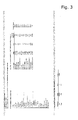
- Fig. 1
- shows in diagram percentage of downtime due to planned repairs versus downtime due to unplanned repairs as well as total downtime;
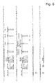
- Fig. 2a
- and
Fig. 2b show a flow chart of a method of the present inventions; - Fig. 3
- to
Fig. 8 show tables used in the method of the invention.
Claims (10)
- A method for maintaining complex systems, e.g. wind turbines comprising the following steps:a. Obtaining physical data of the system recorded by measuring instruments which are relevant for status of the system;b. Establishing an optimal time based service interval schedule in which service intervals are chosen so as to minimize expectation of downtime;c. Calculating the expected downtime due to unplanned repair caused by different failure modes;d. Establishing a condition based plan for repairing or replacing components of the system using the data of step a) in order to minimize downtime due to unplanned repair.
- The method of claim 1, wherein in step a) time series of physical data of the system are recorded by measuring instruments with a predefined first sampling rate.
- The method of one of claims 1 or 2, wherein in step c) failure modes are analysed individually in order to determine the extent to which the introduction of condition monitoring and establishing a condition based plan for repairing or replacing components improve availability of the system.
- The method of claim 3, wherein one failure mode after the other is chosen for introduction of condition monitoring and establishing a condition based plan starting from the one with greatest improvement of availability until an overall availability of the system is satisfactory.
- The method of one of claims 1 to 4, wherein the Weibull distribution is used for statistical representation of lifetime.
- The method of one of claims 1 to 5, wherein in step b) the specific service interval θ*i between two planned maintenance actions is chosen for each failure mode as a multiple of the minimum θ*1 of the specific service intervals θ*i of the high impact failure modes which is less than or equal to the optimal service interval θi of the failure mode.
- The method of one of claims 1 to 6, wherein the following input information is combined:a. systematically collected information about potential failure modes;b. corresponding lifetime models which allow the consideration of prior information about the risk to fail;c. boundary conditions of repair and maintenance actions.
- The method of claim 7, wherein in addition values of a contingency table are considered in order to reflect the prediction accuracy of the failure mode
- The method of one of claims 7 or 8, wherein boundary conditions of repair and maintenance actions are:- the normal repair time tNRT,i is the time [h] which is usually required to fix the failure if it is detected during a planned maintenance service;- the unplanned repair time tURT,i [h] is the time which is usually required to fix the failure if it occurs unplanned;- the emergency response delay tERD,i [h] considers potential spare part order times or tool set-up times as well as the availability of service technicians; and/or- the emergency access time tEAT,i [h] is time required to bring the technicians and tools to the asset location.
- A method applicable to modify the optimization targets for planning new maintenance actions according to the method of one of claims 1 to 9, comprising the following steps:i. analysing the instantaneous failure rate of the system;ii. identifying the corresponding downtimes;iii. considering the load and failure history of the system, in particular that of subsystems and failure modes which have high impact on the system failure rate;iv. selecting those subsystems and failure modes which promise the maximal reduction of downtime;v. changing the optimization targets and consequently the maintenance plan according to the results of steps I to iv.
Applications Claiming Priority (1)
| Application Number | Priority Date | Filing Date | Title |
|---|---|---|---|
| ATA50491/2013A AT514680A2 (en) | 2013-08-05 | 2013-08-05 | Process for optimizing the maintenance of technical systems |
Publications (3)
| Publication Number | Publication Date |
|---|---|
| EP2837984A2 true EP2837984A2 (en) | 2015-02-18 |
| EP2837984A3 EP2837984A3 (en) | 2015-04-22 |
| EP2837984B1 EP2837984B1 (en) | 2019-05-22 |
Family
ID=51301127
Family Applications (1)
| Application Number | Title | Priority Date | Filing Date |
|---|---|---|---|
| EP14179842.1A Active EP2837984B1 (en) | 2013-08-05 | 2014-08-05 | Process to optimize the maintenance of technical systems |
Country Status (4)
| Country | Link |
|---|---|
| EP (1) | EP2837984B1 (en) |
| AT (1) | AT514680A2 (en) |
| DK (1) | DK2837984T3 (en) |
| ES (1) | ES2742298T3 (en) |
Cited By (8)
| Publication number | Priority date | Publication date | Assignee | Title |
|---|---|---|---|---|
| TWI646476B (en) * | 2016-12-09 | 2019-01-01 | 三菱電機股份有限公司 | Fault risk index estimation device and fault risk index estimation method |
| CN109635315A (en) * | 2018-10-29 | 2019-04-16 | 南京航空航天大学 | The Reliability modeling and design guidance method of strategy are reused towards embryo's hardware cell |
| CN111027719A (en) * | 2019-11-14 | 2020-04-17 | 东华大学 | Maintenance optimization method for multi-component system state opportunity |
| WO2020173581A1 (en) * | 2019-02-27 | 2020-09-03 | Siemens Aktiengesellschaft | System, device and method of monitoring condition of a technical installation |
| WO2021008782A1 (en) * | 2019-07-17 | 2021-01-21 | Krones Ag | Predictive maintenance for a device in the food industry by means of a digital twin, and optimized production planning |
| US20220350324A1 (en) * | 2021-05-03 | 2022-11-03 | Kcf Technologies, Inc. | Automatic periodic adjustment of equipment parameters to maximize equipment lifetime |
| CN117038048A (en) * | 2023-10-09 | 2023-11-10 | 江苏优创生物医学科技有限公司 | Remote fault processing method and system for medical instrument |
| DE102022126563A1 (en) | 2022-10-12 | 2024-04-18 | Bayerische Motoren Werke Aktiengesellschaft | Method for generating a decision aid as to whether unscheduled maintenance should be carried out at a production station |
Families Citing this family (6)
| Publication number | Priority date | Publication date | Assignee | Title |
|---|---|---|---|---|
| DE102015225144A1 (en) * | 2015-12-14 | 2017-06-14 | Siemens Aktiengesellschaft | System and method for diagnosing at least one component of a device and / or plant requiring maintenance |
| US12234808B2 (en) | 2019-10-11 | 2025-02-25 | Ge Infrastructure Technology Llc | System and method for scheduling preventative maintenance actions based on operational usage |
| US11635060B2 (en) | 2021-01-20 | 2023-04-25 | General Electric Company | System for operating a wind turbine using cumulative load histograms based on actual operation thereof |
| US11661919B2 (en) | 2021-01-20 | 2023-05-30 | General Electric Company | Odometer-based control of a wind turbine power system |
| US11728654B2 (en) | 2021-03-19 | 2023-08-15 | General Electric Renovables Espana, S.L. | Systems and methods for operating power generating assets |
| CN118504939B (en) * | 2024-07-17 | 2024-10-18 | 国网浙江省电力有限公司杭州供电公司 | Power grid fault electricity protection maintenance plan making method, device, equipment and medium |
Citations (15)
| Publication number | Priority date | Publication date | Assignee | Title |
|---|---|---|---|---|
| US20020000723A1 (en) | 2000-03-09 | 2002-01-03 | Roland Weitkamp | Control system for a wind power plant |
| US20040030524A1 (en) | 2001-12-07 | 2004-02-12 | Battelle Memorial Institute | Methods and systems for analyzing the degradation and failure of mechanical systems |
| JP2004150974A (en) | 2002-10-31 | 2004-05-27 | Nippon Densan Corp | Operation evaluation method and operation evaluation device |
| US20040230377A1 (en) | 2003-05-16 | 2004-11-18 | Seawest Holdings, Inc. | Wind power management system and method |
| US20050090937A1 (en) | 2003-10-22 | 2005-04-28 | Gary Moore | Wind turbine system control |
| WO2008043762A1 (en) | 2006-10-10 | 2008-04-17 | Ecotecnia Energias Renovables, S.L. | Control system for a wind turbine |
| WO2009016020A1 (en) | 2007-07-31 | 2009-02-05 | Vestas Wind Systems A/S | Wind turbine monitoring system |
| US20090037206A1 (en) | 2007-07-31 | 2009-02-05 | Brian Dara Byrne | Method of forecasting maintenance of a machine |
| US20090039650A1 (en) | 2007-08-10 | 2009-02-12 | Jacob Nies | Event monitoring via combination of signals |
| WO2009027509A1 (en) | 2007-08-31 | 2009-03-05 | Vestas Wind Systems A/S | Wind turbine siting and maintenance prediction |
| US20090096405A1 (en) | 2007-10-15 | 2009-04-16 | General Electric Company | Method and system for remotely predicting the remaining life of an ac motor system |
| US20090096406A1 (en) | 2007-10-15 | 2009-04-16 | General Electric Company | Method and system for determining the reliability of a dc motor system |
| WO2009053365A1 (en) | 2007-10-24 | 2009-04-30 | Ecotecnia Energías Renovables, S. L. | Method for determining fatigue damage in a power train of a wind turbine |
| WO2009075649A1 (en) | 2007-12-11 | 2009-06-18 | Vestas Wind Systems A/S | System and method for detecting performance |
| US20110018727A1 (en) | 2009-07-24 | 2011-01-27 | Honeywell International Inc. | Wind turbine generator fault diagnostic and prognostic device and method |
Family Cites Families (4)
| Publication number | Priority date | Publication date | Assignee | Title |
|---|---|---|---|---|
| WO2006035931A1 (en) * | 2004-09-30 | 2006-04-06 | Toshiba Solutions Corporation | Information system reliability evaluation system, reliability evaluation method, and reliability evaluation program |
| GB0704616D0 (en) * | 2007-03-09 | 2007-04-18 | Univ Manchester | Chemical processing system |
| US8660875B2 (en) * | 2009-11-02 | 2014-02-25 | Applied Materials, Inc. | Automated corrective and predictive maintenance system |
| US8370046B2 (en) * | 2010-02-11 | 2013-02-05 | General Electric Company | System and method for monitoring a gas turbine |
-
2013
- 2013-08-05 AT ATA50491/2013A patent/AT514680A2/en not_active Application Discontinuation
-
2014
- 2014-08-05 ES ES14179842T patent/ES2742298T3/en active Active
- 2014-08-05 DK DK14179842.1T patent/DK2837984T3/en active
- 2014-08-05 EP EP14179842.1A patent/EP2837984B1/en active Active
Patent Citations (15)
| Publication number | Priority date | Publication date | Assignee | Title |
|---|---|---|---|---|
| US20020000723A1 (en) | 2000-03-09 | 2002-01-03 | Roland Weitkamp | Control system for a wind power plant |
| US20040030524A1 (en) | 2001-12-07 | 2004-02-12 | Battelle Memorial Institute | Methods and systems for analyzing the degradation and failure of mechanical systems |
| JP2004150974A (en) | 2002-10-31 | 2004-05-27 | Nippon Densan Corp | Operation evaluation method and operation evaluation device |
| US20040230377A1 (en) | 2003-05-16 | 2004-11-18 | Seawest Holdings, Inc. | Wind power management system and method |
| US20050090937A1 (en) | 2003-10-22 | 2005-04-28 | Gary Moore | Wind turbine system control |
| WO2008043762A1 (en) | 2006-10-10 | 2008-04-17 | Ecotecnia Energias Renovables, S.L. | Control system for a wind turbine |
| WO2009016020A1 (en) | 2007-07-31 | 2009-02-05 | Vestas Wind Systems A/S | Wind turbine monitoring system |
| US20090037206A1 (en) | 2007-07-31 | 2009-02-05 | Brian Dara Byrne | Method of forecasting maintenance of a machine |
| US20090039650A1 (en) | 2007-08-10 | 2009-02-12 | Jacob Nies | Event monitoring via combination of signals |
| WO2009027509A1 (en) | 2007-08-31 | 2009-03-05 | Vestas Wind Systems A/S | Wind turbine siting and maintenance prediction |
| US20090096405A1 (en) | 2007-10-15 | 2009-04-16 | General Electric Company | Method and system for remotely predicting the remaining life of an ac motor system |
| US20090096406A1 (en) | 2007-10-15 | 2009-04-16 | General Electric Company | Method and system for determining the reliability of a dc motor system |
| WO2009053365A1 (en) | 2007-10-24 | 2009-04-30 | Ecotecnia Energías Renovables, S. L. | Method for determining fatigue damage in a power train of a wind turbine |
| WO2009075649A1 (en) | 2007-12-11 | 2009-06-18 | Vestas Wind Systems A/S | System and method for detecting performance |
| US20110018727A1 (en) | 2009-07-24 | 2011-01-27 | Honeywell International Inc. | Wind turbine generator fault diagnostic and prognostic device and method |
Cited By (13)
| Publication number | Priority date | Publication date | Assignee | Title |
|---|---|---|---|---|
| TWI646476B (en) * | 2016-12-09 | 2019-01-01 | 三菱電機股份有限公司 | Fault risk index estimation device and fault risk index estimation method |
| CN109635315B (en) * | 2018-10-29 | 2023-12-08 | 南京航空航天大学 | Reliability modeling and design guidance method for embryonic hardware cell reuse strategy |
| CN109635315A (en) * | 2018-10-29 | 2019-04-16 | 南京航空航天大学 | The Reliability modeling and design guidance method of strategy are reused towards embryo's hardware cell |
| WO2020173581A1 (en) * | 2019-02-27 | 2020-09-03 | Siemens Aktiengesellschaft | System, device and method of monitoring condition of a technical installation |
| WO2021008782A1 (en) * | 2019-07-17 | 2021-01-21 | Krones Ag | Predictive maintenance for a device in the food industry by means of a digital twin, and optimized production planning |
| EP4468228A3 (en) * | 2019-07-17 | 2025-02-19 | KRONES Aktiengesellschaft | Predictive maintenance for a device in the food industry by means of a digital twin and optimised production planning |
| CN111027719A (en) * | 2019-11-14 | 2020-04-17 | 东华大学 | Maintenance optimization method for multi-component system state opportunity |
| US11619933B2 (en) * | 2021-05-03 | 2023-04-04 | Kcf Technologies, Inc. | Automatic periodic adjustment of equipment parameters to maximize equipment lifetime |
| US20220350324A1 (en) * | 2021-05-03 | 2022-11-03 | Kcf Technologies, Inc. | Automatic periodic adjustment of equipment parameters to maximize equipment lifetime |
| DE102022126563A1 (en) | 2022-10-12 | 2024-04-18 | Bayerische Motoren Werke Aktiengesellschaft | Method for generating a decision aid as to whether unscheduled maintenance should be carried out at a production station |
| WO2024078873A1 (en) | 2022-10-12 | 2024-04-18 | Bayerische Motoren Werke Aktiengesellschaft | Method for producing a decision aid for deciding whether unscheduled maintenance should be carried out at a production station |
| CN117038048A (en) * | 2023-10-09 | 2023-11-10 | 江苏优创生物医学科技有限公司 | Remote fault processing method and system for medical instrument |
| CN117038048B (en) * | 2023-10-09 | 2023-12-26 | 江苏优创生物医学科技有限公司 | Remote fault processing method and system for medical instrument |
Also Published As
| Publication number | Publication date |
|---|---|
| AT514680A2 (en) | 2015-02-15 |
| DK2837984T3 (en) | 2019-08-19 |
| ES2742298T3 (en) | 2020-02-13 |
| EP2837984A3 (en) | 2015-04-22 |
| EP2837984B1 (en) | 2019-05-22 |
Similar Documents
| Publication | Publication Date | Title |
|---|---|---|
| EP2837984B1 (en) | Process to optimize the maintenance of technical systems | |
| Alaswad et al. | A review on condition-based maintenance optimization models for stochastically deteriorating system | |
| Azadeh et al. | Condition-based maintenance effectiveness for series–parallel power generation system—A combined Markovian simulation model | |
| Van Horenbeek et al. | Quantifying the added value of an imperfectly performing condition monitoring system—Application to a wind turbine gearbox | |
| US7254514B2 (en) | Method and system for predicting remaining life for motors featuring on-line insulation condition monitor | |
| EP2290597B1 (en) | System and method for wind turbine health management | |
| Mathew et al. | Failure mechanisms based prognostics | |
| US20040044499A1 (en) | Method and system for determining motor reliability | |
| EP2051366A1 (en) | Method and system for determining the reliability of a DC motor system | |
| Tiddens et al. | The adoption of prognostic technologies in maintenance decision making: a multiple case study | |
| Koukoura et al. | Influence of extended potential-to-functional failure intervals through condition monitoring systems on offshore wind turbine availability | |
| Ghasemi et al. | Estimating mean residual life for a case study of rail wagon bearings | |
| CN113191506B (en) | A non-periodic situation-based maintenance method considering the uncertainty of equipment detection | |
| US20090096407A1 (en) | Method and system for remotely determining the reliability of a dc motor system | |
| CN114091811A (en) | A nuclear power plant circulating water pump maintenance decision-making system and design method | |
| Gould | Diagnostics “after” prognostics: Steps toward a prognostics-informed analysis of system diagnostic behavior | |
| JP7664870B2 (en) | Equipment reliability and maintenance cost prediction device and equipment reliability and maintenance cost prediction method | |
| Wang et al. | A stochastic filtering based data driven approach for residual life prediction and condition based maintenance decision making support | |
| CN119886511B (en) | System and method for evaluating life cycle of construction device | |
| KR102842755B1 (en) | Lifetime prediction method using tendency diagnosis of machine monitoring data | |
| JP2012234226A (en) | Plant equipment operable period evaluation method and operable period evaluation device | |
| Jodejko-Pietruczuk et al. | Time between inspections optimization for technical object with time delay | |
| Jodejko-Pietruczuk et al. | Block inspection policy model with imperfect inspections for multi-unit systems | |
| Jardine et al. | Interpretation of inspection data emanating from equipment condition monitoring tools: method and software | |
| Kaiser | A simulation study of predictive maintenance policies and how they impact manufacturing systems |
Legal Events
| Date | Code | Title | Description |
|---|---|---|---|
| 17P | Request for examination filed |
Effective date: 20140805 |
|
| AK | Designated contracting states |
Kind code of ref document: A2 Designated state(s): AL AT BE BG CH CY CZ DE DK EE ES FI FR GB GR HR HU IE IS IT LI LT LU LV MC MK MT NL NO PL PT RO RS SE SI SK SM TR |
|
| AX | Request for extension of the european patent |
Extension state: BA ME |
|
| PUAI | Public reference made under article 153(3) epc to a published international application that has entered the european phase |
Free format text: ORIGINAL CODE: 0009012 |
|
| PUAL | Search report despatched |
Free format text: ORIGINAL CODE: 0009013 |
|
| AK | Designated contracting states |
Kind code of ref document: A3 Designated state(s): AL AT BE BG CH CY CZ DE DK EE ES FI FR GB GR HR HU IE IS IT LI LT LU LV MC MK MT NL NO PL PT RO RS SE SI SK SM TR |
|
| AX | Request for extension of the european patent |
Extension state: BA ME |
|
| RIC1 | Information provided on ipc code assigned before grant |
Ipc: G05B 23/02 20060101AFI20150317BHEP |
|
| R17P | Request for examination filed (corrected) |
Effective date: 20150721 |
|
| RBV | Designated contracting states (corrected) |
Designated state(s): AL AT BE BG CH CY CZ DE DK EE ES FI FR GB GR HR HU IE IS IT LI LT LU LV MC MK MT NL NO PL PT RO RS SE SI SK SM TR |
|
| RAP1 | Party data changed (applicant data changed or rights of an application transferred) |
Owner name: UPTIME HOLDING GMBH |
|
| STAA | Information on the status of an ep patent application or granted ep patent |
Free format text: STATUS: EXAMINATION IS IN PROGRESS |
|
| 17Q | First examination report despatched |
Effective date: 20161216 |
|
| GRAP | Despatch of communication of intention to grant a patent |
Free format text: ORIGINAL CODE: EPIDOSNIGR1 |
|
| STAA | Information on the status of an ep patent application or granted ep patent |
Free format text: STATUS: GRANT OF PATENT IS INTENDED |
|
| GRAS | Grant fee paid |
Free format text: ORIGINAL CODE: EPIDOSNIGR3 |
|
| INTG | Intention to grant announced |
Effective date: 20190319 |
|
| RIN1 | Information on inventor provided before grant (corrected) |
Inventor name: GRAY, CHRISTOPHER Inventor name: HASELGRUBER, NIKOLAUS Inventor name: LANGMAYR, FRANZ |
|
| GRAA | (expected) grant |
Free format text: ORIGINAL CODE: 0009210 |
|
| STAA | Information on the status of an ep patent application or granted ep patent |
Free format text: STATUS: THE PATENT HAS BEEN GRANTED |
|
| AK | Designated contracting states |
Kind code of ref document: B1 Designated state(s): AL AT BE BG CH CY CZ DE DK EE ES FI FR GB GR HR HU IE IS IT LI LT LU LV MC MK MT NL NO PL PT RO RS SE SI SK SM TR |
|
| REG | Reference to a national code |
Ref country code: GB Ref legal event code: FG4D |
|
| REG | Reference to a national code |
Ref country code: CH Ref legal event code: EP |
|
| REG | Reference to a national code |
Ref country code: IE Ref legal event code: FG4D |
|
| REG | Reference to a national code |
Ref country code: DE Ref legal event code: R096 Ref document number: 602014047110 Country of ref document: DE |
|
| REG | Reference to a national code |
Ref country code: AT Ref legal event code: REF Ref document number: 1136878 Country of ref document: AT Kind code of ref document: T Effective date: 20190615 |
|
| REG | Reference to a national code |
Ref country code: DK Ref legal event code: T3 Effective date: 20190816 |
|
| REG | Reference to a national code |
Ref country code: NL Ref legal event code: MP Effective date: 20190522 |
|
| REG | Reference to a national code |
Ref country code: LT Ref legal event code: MG4D |
|
| PG25 | Lapsed in a contracting state [announced via postgrant information from national office to epo] |
Ref country code: SE Free format text: LAPSE BECAUSE OF FAILURE TO SUBMIT A TRANSLATION OF THE DESCRIPTION OR TO PAY THE FEE WITHIN THE PRESCRIBED TIME-LIMIT Effective date: 20190522 Ref country code: PT Free format text: LAPSE BECAUSE OF FAILURE TO SUBMIT A TRANSLATION OF THE DESCRIPTION OR TO PAY THE FEE WITHIN THE PRESCRIBED TIME-LIMIT Effective date: 20190922 Ref country code: AL Free format text: LAPSE BECAUSE OF FAILURE TO SUBMIT A TRANSLATION OF THE DESCRIPTION OR TO PAY THE FEE WITHIN THE PRESCRIBED TIME-LIMIT Effective date: 20190522 Ref country code: NO Free format text: LAPSE BECAUSE OF FAILURE TO SUBMIT A TRANSLATION OF THE DESCRIPTION OR TO PAY THE FEE WITHIN THE PRESCRIBED TIME-LIMIT Effective date: 20190822 Ref country code: FI Free format text: LAPSE BECAUSE OF FAILURE TO SUBMIT A TRANSLATION OF THE DESCRIPTION OR TO PAY THE FEE WITHIN THE PRESCRIBED TIME-LIMIT Effective date: 20190522 Ref country code: NL Free format text: LAPSE BECAUSE OF FAILURE TO SUBMIT A TRANSLATION OF THE DESCRIPTION OR TO PAY THE FEE WITHIN THE PRESCRIBED TIME-LIMIT Effective date: 20190522 Ref country code: HR Free format text: LAPSE BECAUSE OF FAILURE TO SUBMIT A TRANSLATION OF THE DESCRIPTION OR TO PAY THE FEE WITHIN THE PRESCRIBED TIME-LIMIT Effective date: 20190522 Ref country code: LT Free format text: LAPSE BECAUSE OF FAILURE TO SUBMIT A TRANSLATION OF THE DESCRIPTION OR TO PAY THE FEE WITHIN THE PRESCRIBED TIME-LIMIT Effective date: 20190522 |
|
| PG25 | Lapsed in a contracting state [announced via postgrant information from national office to epo] |
Ref country code: RS Free format text: LAPSE BECAUSE OF FAILURE TO SUBMIT A TRANSLATION OF THE DESCRIPTION OR TO PAY THE FEE WITHIN THE PRESCRIBED TIME-LIMIT Effective date: 20190522 Ref country code: GR Free format text: LAPSE BECAUSE OF FAILURE TO SUBMIT A TRANSLATION OF THE DESCRIPTION OR TO PAY THE FEE WITHIN THE PRESCRIBED TIME-LIMIT Effective date: 20190823 Ref country code: BG Free format text: LAPSE BECAUSE OF FAILURE TO SUBMIT A TRANSLATION OF THE DESCRIPTION OR TO PAY THE FEE WITHIN THE PRESCRIBED TIME-LIMIT Effective date: 20190822 Ref country code: LV Free format text: LAPSE BECAUSE OF FAILURE TO SUBMIT A TRANSLATION OF THE DESCRIPTION OR TO PAY THE FEE WITHIN THE PRESCRIBED TIME-LIMIT Effective date: 20190522 |
|
| PG25 | Lapsed in a contracting state [announced via postgrant information from national office to epo] |
Ref country code: CZ Free format text: LAPSE BECAUSE OF FAILURE TO SUBMIT A TRANSLATION OF THE DESCRIPTION OR TO PAY THE FEE WITHIN THE PRESCRIBED TIME-LIMIT Effective date: 20190522 Ref country code: EE Free format text: LAPSE BECAUSE OF FAILURE TO SUBMIT A TRANSLATION OF THE DESCRIPTION OR TO PAY THE FEE WITHIN THE PRESCRIBED TIME-LIMIT Effective date: 20190522 Ref country code: RO Free format text: LAPSE BECAUSE OF FAILURE TO SUBMIT A TRANSLATION OF THE DESCRIPTION OR TO PAY THE FEE WITHIN THE PRESCRIBED TIME-LIMIT Effective date: 20190522 Ref country code: SK Free format text: LAPSE BECAUSE OF FAILURE TO SUBMIT A TRANSLATION OF THE DESCRIPTION OR TO PAY THE FEE WITHIN THE PRESCRIBED TIME-LIMIT Effective date: 20190522 |
|
| REG | Reference to a national code |
Ref country code: ES Ref legal event code: FG2A Ref document number: 2742298 Country of ref document: ES Kind code of ref document: T3 Effective date: 20200213 |
|
| REG | Reference to a national code |
Ref country code: DE Ref legal event code: R097 Ref document number: 602014047110 Country of ref document: DE |
|
| PG25 | Lapsed in a contracting state [announced via postgrant information from national office to epo] |
Ref country code: SM Free format text: LAPSE BECAUSE OF FAILURE TO SUBMIT A TRANSLATION OF THE DESCRIPTION OR TO PAY THE FEE WITHIN THE PRESCRIBED TIME-LIMIT Effective date: 20190522 Ref country code: IT Free format text: LAPSE BECAUSE OF FAILURE TO SUBMIT A TRANSLATION OF THE DESCRIPTION OR TO PAY THE FEE WITHIN THE PRESCRIBED TIME-LIMIT Effective date: 20190522 |
|
| PLBE | No opposition filed within time limit |
Free format text: ORIGINAL CODE: 0009261 |
|
| STAA | Information on the status of an ep patent application or granted ep patent |
Free format text: STATUS: NO OPPOSITION FILED WITHIN TIME LIMIT |
|
| PG25 | Lapsed in a contracting state [announced via postgrant information from national office to epo] |
Ref country code: TR Free format text: LAPSE BECAUSE OF FAILURE TO SUBMIT A TRANSLATION OF THE DESCRIPTION OR TO PAY THE FEE WITHIN THE PRESCRIBED TIME-LIMIT Effective date: 20190522 |
|
| 26N | No opposition filed |
Effective date: 20200225 |
|
| PG25 | Lapsed in a contracting state [announced via postgrant information from national office to epo] |
Ref country code: PL Free format text: LAPSE BECAUSE OF FAILURE TO SUBMIT A TRANSLATION OF THE DESCRIPTION OR TO PAY THE FEE WITHIN THE PRESCRIBED TIME-LIMIT Effective date: 20190522 |
|
| PG25 | Lapsed in a contracting state [announced via postgrant information from national office to epo] |
Ref country code: MC Free format text: LAPSE BECAUSE OF FAILURE TO SUBMIT A TRANSLATION OF THE DESCRIPTION OR TO PAY THE FEE WITHIN THE PRESCRIBED TIME-LIMIT Effective date: 20190522 Ref country code: CH Free format text: LAPSE BECAUSE OF NON-PAYMENT OF DUE FEES Effective date: 20190831 Ref country code: SI Free format text: LAPSE BECAUSE OF FAILURE TO SUBMIT A TRANSLATION OF THE DESCRIPTION OR TO PAY THE FEE WITHIN THE PRESCRIBED TIME-LIMIT Effective date: 20190522 Ref country code: LI Free format text: LAPSE BECAUSE OF NON-PAYMENT OF DUE FEES Effective date: 20190831 Ref country code: LU Free format text: LAPSE BECAUSE OF NON-PAYMENT OF DUE FEES Effective date: 20190805 |
|
| REG | Reference to a national code |
Ref country code: BE Ref legal event code: MM Effective date: 20190831 |
|
| PG25 | Lapsed in a contracting state [announced via postgrant information from national office to epo] |
Ref country code: FR Free format text: LAPSE BECAUSE OF NON-PAYMENT OF DUE FEES Effective date: 20190831 Ref country code: IE Free format text: LAPSE BECAUSE OF NON-PAYMENT OF DUE FEES Effective date: 20190805 |
|
| PG25 | Lapsed in a contracting state [announced via postgrant information from national office to epo] |
Ref country code: BE Free format text: LAPSE BECAUSE OF NON-PAYMENT OF DUE FEES Effective date: 20190831 |
|
| PG25 | Lapsed in a contracting state [announced via postgrant information from national office to epo] |
Ref country code: CY Free format text: LAPSE BECAUSE OF FAILURE TO SUBMIT A TRANSLATION OF THE DESCRIPTION OR TO PAY THE FEE WITHIN THE PRESCRIBED TIME-LIMIT Effective date: 20190522 |
|
| PG25 | Lapsed in a contracting state [announced via postgrant information from national office to epo] |
Ref country code: IS Free format text: LAPSE BECAUSE OF FAILURE TO SUBMIT A TRANSLATION OF THE DESCRIPTION OR TO PAY THE FEE WITHIN THE PRESCRIBED TIME-LIMIT Effective date: 20190922 |
|
| PG25 | Lapsed in a contracting state [announced via postgrant information from national office to epo] |
Ref country code: HU Free format text: LAPSE BECAUSE OF FAILURE TO SUBMIT A TRANSLATION OF THE DESCRIPTION OR TO PAY THE FEE WITHIN THE PRESCRIBED TIME-LIMIT; INVALID AB INITIO Effective date: 20140805 Ref country code: MT Free format text: LAPSE BECAUSE OF FAILURE TO SUBMIT A TRANSLATION OF THE DESCRIPTION OR TO PAY THE FEE WITHIN THE PRESCRIBED TIME-LIMIT Effective date: 20190522 |
|
| REG | Reference to a national code |
Ref country code: AT Ref legal event code: UEP Ref document number: 1136878 Country of ref document: AT Kind code of ref document: T Effective date: 20190522 |
|
| PG25 | Lapsed in a contracting state [announced via postgrant information from national office to epo] |
Ref country code: MK Free format text: LAPSE BECAUSE OF FAILURE TO SUBMIT A TRANSLATION OF THE DESCRIPTION OR TO PAY THE FEE WITHIN THE PRESCRIBED TIME-LIMIT Effective date: 20190522 |
|
| PGFP | Annual fee paid to national office [announced via postgrant information from national office to epo] |
Ref country code: DK Payment date: 20220824 Year of fee payment: 9 |
|
| PGFP | Annual fee paid to national office [announced via postgrant information from national office to epo] |
Ref country code: ES Payment date: 20221024 Year of fee payment: 9 |
|
| REG | Reference to a national code |
Ref country code: DK Ref legal event code: EBP Effective date: 20230831 |
|
| PG25 | Lapsed in a contracting state [announced via postgrant information from national office to epo] |
Ref country code: DK Free format text: LAPSE BECAUSE OF NON-PAYMENT OF DUE FEES Effective date: 20230831 |
|
| PG25 | Lapsed in a contracting state [announced via postgrant information from national office to epo] |
Ref country code: DK Free format text: LAPSE BECAUSE OF NON-PAYMENT OF DUE FEES Effective date: 20230831 |
|
| REG | Reference to a national code |
Ref country code: ES Ref legal event code: FD2A Effective date: 20240927 |
|
| PG25 | Lapsed in a contracting state [announced via postgrant information from national office to epo] |
Ref country code: ES Free format text: LAPSE BECAUSE OF NON-PAYMENT OF DUE FEES Effective date: 20230806 |
|
| PG25 | Lapsed in a contracting state [announced via postgrant information from national office to epo] |
Ref country code: ES Free format text: LAPSE BECAUSE OF NON-PAYMENT OF DUE FEES Effective date: 20230806 |
|
| PGFP | Annual fee paid to national office [announced via postgrant information from national office to epo] |
Ref country code: DE Payment date: 20250820 Year of fee payment: 12 |
|
| PGFP | Annual fee paid to national office [announced via postgrant information from national office to epo] |
Ref country code: GB Payment date: 20250820 Year of fee payment: 12 |
|
| PGFP | Annual fee paid to national office [announced via postgrant information from national office to epo] |
Ref country code: AT Payment date: 20250704 Year of fee payment: 12 |