EP2837887A1 - Combustor of a gas turbine with pressure drop optimized liner cooling - Google Patents
Combustor of a gas turbine with pressure drop optimized liner cooling Download PDFInfo
- Publication number
- EP2837887A1 EP2837887A1 EP13180549.1A EP13180549A EP2837887A1 EP 2837887 A1 EP2837887 A1 EP 2837887A1 EP 13180549 A EP13180549 A EP 13180549A EP 2837887 A1 EP2837887 A1 EP 2837887A1
- Authority
- EP
- European Patent Office
- Prior art keywords
- liner
- effusion holes
- combustor
- combustor according
- foregoing
- Prior art date
- Legal status (The legal status is an assumption and is not a legal conclusion. Google has not performed a legal analysis and makes no representation as to the accuracy of the status listed.)
- Granted
Links
Images



Classifications
-
- F—MECHANICAL ENGINEERING; LIGHTING; HEATING; WEAPONS; BLASTING
- F23—COMBUSTION APPARATUS; COMBUSTION PROCESSES
- F23R—GENERATING COMBUSTION PRODUCTS OF HIGH PRESSURE OR HIGH VELOCITY, e.g. GAS-TURBINE COMBUSTION CHAMBERS
- F23R3/00—Continuous combustion chambers using liquid or gaseous fuel
- F23R3/002—Wall structures
-
- F—MECHANICAL ENGINEERING; LIGHTING; HEATING; WEAPONS; BLASTING
- F23—COMBUSTION APPARATUS; COMBUSTION PROCESSES
- F23R—GENERATING COMBUSTION PRODUCTS OF HIGH PRESSURE OR HIGH VELOCITY, e.g. GAS-TURBINE COMBUSTION CHAMBERS
- F23R3/00—Continuous combustion chambers using liquid or gaseous fuel
- F23R3/02—Continuous combustion chambers using liquid or gaseous fuel characterised by the air-flow or gas-flow configuration
- F23R3/04—Air inlet arrangements
-
- F—MECHANICAL ENGINEERING; LIGHTING; HEATING; WEAPONS; BLASTING
- F23—COMBUSTION APPARATUS; COMBUSTION PROCESSES
- F23R—GENERATING COMBUSTION PRODUCTS OF HIGH PRESSURE OR HIGH VELOCITY, e.g. GAS-TURBINE COMBUSTION CHAMBERS
- F23R3/00—Continuous combustion chambers using liquid or gaseous fuel
- F23R3/02—Continuous combustion chambers using liquid or gaseous fuel characterised by the air-flow or gas-flow configuration
- F23R3/16—Continuous combustion chambers using liquid or gaseous fuel characterised by the air-flow or gas-flow configuration with devices inside the flame tube or the combustion chamber to influence the air or gas flow
-
- F—MECHANICAL ENGINEERING; LIGHTING; HEATING; WEAPONS; BLASTING
- F02—COMBUSTION ENGINES; HOT-GAS OR COMBUSTION-PRODUCT ENGINE PLANTS
- F02C—GAS-TURBINE PLANTS; AIR INTAKES FOR JET-PROPULSION PLANTS; CONTROLLING FUEL SUPPLY IN AIR-BREATHING JET-PROPULSION PLANTS
- F02C3/00—Gas-turbine plants characterised by the use of combustion products as the working fluid
-
- F—MECHANICAL ENGINEERING; LIGHTING; HEATING; WEAPONS; BLASTING
- F23—COMBUSTION APPARATUS; COMBUSTION PROCESSES
- F23R—GENERATING COMBUSTION PRODUCTS OF HIGH PRESSURE OR HIGH VELOCITY, e.g. GAS-TURBINE COMBUSTION CHAMBERS
- F23R3/00—Continuous combustion chambers using liquid or gaseous fuel
- F23R3/02—Continuous combustion chambers using liquid or gaseous fuel characterised by the air-flow or gas-flow configuration
- F23R3/04—Air inlet arrangements
- F23R3/06—Arrangement of apertures along the flame tube
-
- F—MECHANICAL ENGINEERING; LIGHTING; HEATING; WEAPONS; BLASTING
- F23—COMBUSTION APPARATUS; COMBUSTION PROCESSES
- F23R—GENERATING COMBUSTION PRODUCTS OF HIGH PRESSURE OR HIGH VELOCITY, e.g. GAS-TURBINE COMBUSTION CHAMBERS
- F23R2900/00—Special features of, or arrangements for continuous combustion chambers; Combustion processes therefor
- F23R2900/00018—Manufacturing combustion chamber liners or subparts
-
- F—MECHANICAL ENGINEERING; LIGHTING; HEATING; WEAPONS; BLASTING
- F23—COMBUSTION APPARATUS; COMBUSTION PROCESSES
- F23R—GENERATING COMBUSTION PRODUCTS OF HIGH PRESSURE OR HIGH VELOCITY, e.g. GAS-TURBINE COMBUSTION CHAMBERS
- F23R2900/00—Special features of, or arrangements for continuous combustion chambers; Combustion processes therefor
- F23R2900/03041—Effusion cooled combustion chamber walls or domes
-
- F—MECHANICAL ENGINEERING; LIGHTING; HEATING; WEAPONS; BLASTING
- F23—COMBUSTION APPARATUS; COMBUSTION PROCESSES
- F23R—GENERATING COMBUSTION PRODUCTS OF HIGH PRESSURE OR HIGH VELOCITY, e.g. GAS-TURBINE COMBUSTION CHAMBERS
- F23R2900/00—Special features of, or arrangements for continuous combustion chambers; Combustion processes therefor
- F23R2900/03045—Convection cooled combustion chamber walls provided with turbolators or means for creating turbulences to increase cooling
Definitions
- the invention refers to gas turbines and is directed to a gas turbine with an air-cooled combustor.
- FIG. 1 illustrates a schematic and simplified cross section through a gas turbine GT24/GT26.
- the compressed air that enters the burner (no reference number) is denominated with reference number 1.
- the compressed air 1 is fed into the burner creating a homogenous, lean fuel/air mixture.
- This mixture of fuel and air is burned in a first combustor 2 forming a single, annular flame ring.
- This flame ring has an inner recirculation zone that stabilizes the flame in the free space within the combustion zone.
- the hot exhaust gas exiting the first combustor 2 moves through the high-pressure turbine stage before entering the second burner 4 of the second combustor 5.
- the claimed invention is directed to the first combustor 2 and / or the second combustor 5.
- the combustors 2 and 5 are in radial direction bordered by liners 7. These liners 7 are the outer walls of the combustors 2 and 5 and are exposed to high temperatures resulting from the flames.
- the liners 7 are cooled by impingement cooling and convective cooling using compressed cooling air.
- the cooling air flows through annular channels 9.
- the annular channels 9 are bordered by cover plates 11 (in case of combustor 5) or carrier structures (in case of combustor 2).
- the cooling air flows through the channels 9 in figure 1 from left to right.
- the cooling air is delivered by a compressor of the gas turbine (not shown) which also delivers compressed air into the first burner 1.
- Prior art gas turbines have a pressure drop in the channels 9 of the first combustor 2 of approximately 2-3 per cent [%] relative to pin (compressor end pressure).
- a combustor of a gas turbine comprising a liner and a cover plate, wherein the liner and the cover plate border a channel for cooling air, and wherein the cover plate forms at its upstream end a nozzle at the beginning of the channel for cooling air.
- the geometry of the claimed nozzle may be similar to the first part of a laval nozzle. It may also be in a longitudinal direction circular or parabolic shaped.
- the geometry of the nozzle may also be different from the a. m. examples, for reasons of even better flow of cooling air and/or an easier manufacture.
- the pressure drop may be significantly reduced compared to tubular or cylindrical cover plates as are known from the prior art. Pressure drop reduction of up to 0.5% relative to pin is expected by introducing a nozzle at the beginning of the cover plate.
- Impingement cooling is very effective to reduce the temperature of the liner, but causes high pressure drops of the cooling air. Therefore the cooling air has to be compressed to a high pressure, which reduces the overall efficiency of the gas turbine.
- Impingement cooling uses typically 0.5% to 1.5% pressure drop relative to compressor end pressure.
- One further important aspect of the claimed invention is to provide very long effusion holes. This means that at least some of the effusion holes of the claimed combustor liner are longer than 15 mm.
- a length of up to 15 mm allows manufacturing the effusion holes into the liner by means of a laser. Thicknesses of more than 15 mm cannot be made by means of a laser.
- These grooves may cover the length of the effusion holes that are above 15 mm. These grooves may be cast along with casting the liner 7. To complete these very long effusion holes, it is claimed to cover these grooves by a covering. This results in effusion holes that are longer than 15 mm and can be designed as required. For example, the effusion holes can be bent to optimize the heat transfer form the liner to the cooling air that flows through the effusion holes.
- a further aspect of the claimed invention is that over a section of the effusion holes their longitudinal axis is parallel to at least one surface of the liner.
- the longitudinal axis of the effusion holes is parallel to the longitudinal axis of the liner.
- the liner in the section of where the effusion holes are parallel to the at least one surface of the liner, the liner has a greater thickness than in a channel section of the liner. This channel section is located downstream of the effusion holes.
- the cover plates and especially the nozzle part of the cover plates extends in axial direction over at least one row of effusion holes.
- section with effusion cooling and the section with convection cooling overlap a bit in axial direction. Consequently all areas of the liner are appropriately cooled and no local overheating occurs.
- the rows of effusion holes extend in axial direction of the liner over a length of more than 5 cm, preferable more than 10 cm or even more than 15 cm.
- the liner by casting or by selective laser melting.
- By casting the liner it is possible for example to form the grooves into the casting mold. Doing so, size and geometry of this part of the effusion holes are nearly unrestricted and can be designed to achieve optimal cooling effects.
- the liner is produced by selective laser melting, it is even possible to have three-dimensionally bent effusion holes.
- the technology of selective laser melting enables even more degrees of freedom as far as size and geometry of the effusion holes are concerned.
- the upstream end of the cover plate 11 is a bent to form a nozzle 13.
- the nozzle 13 may be circular and/or parabolic. It may also have shape of the entrance of a laval nozzle.
- the cooling air flow is illustrated by several arrows 15. For reasons of clarity, not all of these arrows have the reference numeral 15.
- An arrow 17 shows the general direction of flow of the cooling air in figures 2 to 5 from left to right.
- the arrow 17 starts at the upstream end or the beginning of the liner 7 and points towards the downstream end (not shown) of the liner 7.
- This arrow 17 is parallel to the longitudinal direction of the liner 7.
- this embodiment comprises at the upstream end of the liner 7 several rows of effusion holes 19.
- Each row of effusion holes 19 is arranged circumferentially around the liner 7. Consequently, from each row in figure 2 only one effusion hole 19 is illustrated in figure 2 .
- the rows of effusion holes 19 extend in axial direction from the beginning of the liner 7 towards the downstream end of the liner 7.
- the liner 7 is cooled by convective cooling.
- the convective cooling is achieved by rows of effusion holes 19. These rows of effusion holes extend further downstream than the (beginning of the) nozzle 13.
- the convective cooling of the cooling air in the channel 9 is intensified by turbulators 25 on the outer surface of the liner 7. This means that the turbulators 25 cover a part of the wall of the channel 9.
- the effusion holes 19 are drilled under an angle of approximately 30 to 45 degrees to the axial direction of the liner 7 (c. f. arrow 17), they are approximately 1.4 times longer than the local thickness of the liner 7.
- the angle between the effusion holes 19 and the axial direction of the liner 7 (cf. reference numeral 17) is one possibility to influence the cooling effect of the effusion holes.
- the number of effusion holes 19 is a further possibility to influence the cooling effect and the cooling air demand for this part of the inventive convective cooling.
- the cooling air 15 has a pressure p in which may be about 17 bars.
- the cooling air 15 Due to the unavoidable pressure drops in the channel 9, the cooling air 15 has a reduced pressure p in minus ⁇ p at the end of the channel 9.
- the pressure drop ⁇ p according to this embodiment are approximately 1 to 2 per cent of p in .
- the pressure drop ⁇ p is approximately 2-3 per cent of pin.
- FIG 3 shows a second embodiment of the claimed invention with even longer effusion holes 19.
- the effusion holes 19 are drilled at the upstream end of the liner 7. Downstream of a wall 27 the effusion holes 19 are constituted by grooves 29, which may be cast together with the liner 7 and its turbulators 25. These grooves 29 are closed to by a covering 31 resulting in channel-like effusion holes.
- the covering 31 may be fixed to the liner 7 by screws, welds or fixation pins.
- 15 mm is a limit for drilling effusion holes 19 by means of a laser, if the liner 7 is made of steel or a temperature resistant alloy.
- this embodiment has only convective cooling from the beginning of the liner 7. At the upstream end of the liner 7 there is convective cooling inside each effusion hole 19.
- This embodiment comprises only one row of circumferentially arranged effusion holes 19. These effusion holes 19 are very long compared to the thickness of the liner 7. They may be 5 to 10 times longer than the thickness of the liner 7 due to the possibility of combining a drilled part of the effusion holes 19 with a section of the effusion holes where they are constituted by grooves 29 and their coverings 31.
- the effusion holes 19 are very long compared to the thickness of the liner.
- the effusion holes 19 are bent and they also comprise a drilled part (which is at the left at the upstream end of the liner 7) and a second part 33, which may again be manufactured by casting grooves and covering these grooves with a covering.
- This method of manufacture comprises locally melting a powder of metal in a way that the liner 7 with its complex geometry including the effusion holes is created by locally melting the powder of metal.
- Selective laser melting is a method that is known to a man skilled in the art and therefore is not described in detail in this application.
- the section 33 ends in longitudinal direction at the beginning of the nozzle 13. It is also possible to elongate the section 33 until it extends into the channel 9.
- Figure 5 shows a further embodiment with a very long effusion hole 19 compared to the local thickness of the liner 7.
- effusion holes 19 that are more or less parallel to a surface 35 of the liner 7 makes it necessary in some cases to raise the thickness of the liner in the upper part where effusion takes please (the bar 21 in figures 3 to 5 ).
Landscapes
- Engineering & Computer Science (AREA)
- Chemical & Material Sciences (AREA)
- Combustion & Propulsion (AREA)
- Mechanical Engineering (AREA)
- General Engineering & Computer Science (AREA)
- Turbine Rotor Nozzle Sealing (AREA)
- Laser Beam Processing (AREA)
Description
- The invention refers to gas turbines and is directed to a gas turbine with an air-cooled combustor.
- From the market gas turbines with air-cooled combustors are known. For example the applicant successfully produces gas turbines of this type under the name GT24/GT26.
Figure 1 illustrates a schematic and simplified cross section through a gas turbine GT24/GT26. - Neither the rotor nor the axis of rotation of this gas turbine are shown in
figure 1 . This means that some of the components that are illustrated infigure 1 have an annular geometry. - Starting from the left in
figure 1 the compressed air that enters the burner (no reference number) is denominated with reference number 1. The compressed air 1 is fed into the burner creating a homogenous, lean fuel/air mixture. - This mixture of fuel and air is burned in a
first combustor 2 forming a single, annular flame ring. This flame ring has an inner recirculation zone that stabilizes the flame in the free space within the combustion zone. - The hot exhaust gas exiting the
first combustor 2 moves through the high-pressure turbine stage before entering the second burner 4 of thesecond combustor 5. - The claimed invention is directed to the
first combustor 2 and / or thesecond combustor 5. - As can be seen from
figure 1 , thecombustors liners 7. Theseliners 7 are the outer walls of thecombustors - The
liners 7 are cooled by impingement cooling and convective cooling using compressed cooling air. The cooling air flows throughannular channels 9. Theannular channels 9 are bordered by cover plates 11 (in case of combustor 5) or carrier structures (in case of combustor 2). - The cooling air flows through the
channels 9 infigure 1 from left to right. The cooling air is delivered by a compressor of the gas turbine (not shown) which also delivers compressed air into the first burner 1. - Since compressing air requires mechanical energy, it is always a goal to reduce the cooling air consumption and/or the pressure drop of the cooling air in the
channels 9, since this raises the efficiency and the power output of the gas turbine. - Prior art gas turbines have a pressure drop in the
channels 9 of thefirst combustor 2 of approximately 2-3 per cent [%] relative to pin (compressor end pressure). - As mentioned before, in
figure 1 the cooling air flows figure is from left to right. This means that "upstream" is equivalent to "on the left side" offigure 1 (and thefigures 2 to 5 ). The term "downstream" is related to the more right part of the figures. Anyway, the terms "upstream" and "downstream" are related to the flow direction of the cooling air. - It is an objective of the claimed invention to reduce the pressure drop of the cooling air of the combustors and / or to reduce the amount of cooling air required for the cooling of the first and / or second combustor of a gas turbine.
- This goal is achieved by a combustor of a gas turbine comprising a liner and a cover plate, wherein the liner and the cover plate border a channel for cooling air, and wherein the cover plate forms at its upstream end a nozzle at the beginning of the channel for cooling air.
- Doing so, the pressure drop due to turbulences of the cooling air at the entrance into the channel is reduced. As a result, the pressure drop of the cooling air is reduced significantly.
- The geometry of the claimed nozzle may be similar to the first part of a laval nozzle. It may also be in a longitudinal direction circular or parabolic shaped.
- The geometry of the nozzle may also be different from the a. m. examples, for reasons of even better flow of cooling air and/or an easier manufacture.
- For example, it is possible to optimize the geometry of the nozzle by 1-D, 2-D or 3-D flow simulations of the cooling air flow.
- By designing the beginning of the cover plate (at the upstream side of the channel) as a nozzle, the pressure drop may be significantly reduced compared to tubular or cylindrical cover plates as are known from the prior art. Pressure drop reduction of up to 0.5% relative to pin is expected by introducing a nozzle at the beginning of the cover plate.
- It is further possible to reduce the pressure drop losses by drilling effusion holes in the liner and in that at least one of the effusion holes is longer than 1.4 times the local thickness of the liner.
- Doing so, it is possible to effectively cool the upstream end of the liner without impingement cooling as is known from the prior art. Impingement cooling is very effective to reduce the temperature of the liner, but causes high pressure drops of the cooling air. Therefore the cooling air has to be compressed to a high pressure, which reduces the overall efficiency of the gas turbine.
- By avoiding impingement cooling at the upstream end of the liner, it is possible to further reduce the pressure drop of the cooling air significantly. Impingement cooling uses typically 0.5% to 1.5% pressure drop relative to compressor end pressure.
- One further important aspect of the claimed invention is to provide very long effusion holes. This means that at least some of the effusion holes of the claimed combustor liner are longer than 15 mm.
- A length of up to 15 mm allows manufacturing the effusion holes into the liner by means of a laser. Thicknesses of more than 15 mm cannot be made by means of a laser.
- The achieve the claimed length of more than 15 millimeters in a further embodiment of the claimed invention it is claimed that at least some of the effusion holes are partially bordered by a groove in the liner and a covering.
- These grooves may cover the length of the effusion holes that are above 15 mm. These grooves may be cast along with casting the
liner 7. To complete these very long effusion holes, it is claimed to cover these grooves by a covering. This results in effusion holes that are longer than 15 mm and can be designed as required. For example, the effusion holes can be bent to optimize the heat transfer form the liner to the cooling air that flows through the effusion holes. - A further aspect of the claimed invention is that over a section of the effusion holes their longitudinal axis is parallel to at least one surface of the liner.
- This means that the effusion holes very effectively cool a certain area at the upstream end of the liner. Therefore, no impingement cooling of this area of the liner is required.
- In this case, it is preferred if the longitudinal axis of the effusion holes is parallel to the longitudinal axis of the liner.
- To facilitate the manufacture of these effusion holes, it is claimed that in the section of where the effusion holes are parallel to the at least one surface of the liner, the liner has a greater thickness than in a channel section of the liner. This channel section is located downstream of the effusion holes.
- Doing so, it is possible to have long effusion holes at the upstream end of the liner and it is further possible to produce these effusion holes by means of a laser for the first 15 mm. The additional length of the effusion holes can be made for example by drilling. It is also possible to drill the whole length of the effusion holes.
- In a further embodiment of the claimed invention, the cover plates and especially the nozzle part of the cover plates extends in axial direction over at least one row of effusion holes.
- This means that at the upstream end of the liner the effusion holes cool the liner and in the more downstream part of the liner it is the cooling air flowing through the channel that supply the convective cooling of.
- In a further advantageous embodiment of the invention the section with effusion cooling and the section with convection cooling overlap a bit in axial direction. Consequently all areas of the liner are appropriately cooled and no local overheating occurs.
- It has been proven advantageous if at the upstream end of the liner the rows of effusion holes extend in axial direction of the liner over a length of more than 5 cm, preferable more than 10 cm or even more than 15 cm.
- It is possible to produce the liner by casting or by selective laser melting. By casting the liner, it is possible for example to form the grooves into the casting mold. Doing so, size and geometry of this part of the effusion holes are nearly unrestricted and can be designed to achieve optimal cooling effects.
- In case the liner is produced by selective laser melting, it is even possible to have three-dimensionally bent effusion holes. The technology of selective laser melting enables even more degrees of freedom as far as size and geometry of the effusion holes are concerned.
- Further advantages and features are disclosed in the figures and their descriptions:
-
- Figure 1
- shows a cross-section of a gas turbine (prior art);
- Figure 2
- shows a first embodiment of the claimed invention comprising several rows of effusion holes and
- Figures 3 to 5
- show further embodiments of effusion holes.
- Starting with the first embodiment of the claimed invention, it can be seen that the upstream end of the
cover plate 11 is a bent to form anozzle 13. - In a longitudinal section the
nozzle 13 may be circular and/or parabolic. It may also have shape of the entrance of a laval nozzle. - The cooling air flow is illustrated by
several arrows 15. For reasons of clarity, not all of these arrows have thereference numeral 15. - An
arrow 17 shows the general direction of flow of the cooling air infigures 2 to 5 from left to right. In other words: thearrow 17 starts at the upstream end or the beginning of theliner 7 and points towards the downstream end (not shown) of theliner 7. Thisarrow 17 is parallel to the longitudinal direction of theliner 7. - As can be seen from
figure 2 this embodiment comprises at the upstream end of theliner 7 several rows of effusion holes 19. - Each row of effusion holes 19 is arranged circumferentially around the
liner 7. Consequently, from each row infigure 2 only oneeffusion hole 19 is illustrated infigure 2 . - As can be further seen from
figure 2 , the rows of effusion holes 19 extend in axial direction from the beginning of theliner 7 towards the downstream end of theliner 7. - The axial extension of these rows of effusion holes 19 is illustrated in
figure 2 by means of theline 21. - As is illustrated by the
line 23 from the beginning of theliner 7 towards the end of theliner 7, theliner 7 is cooled by convective cooling. At the upstream beginning of theliner 7, the convective cooling is achieved by rows of effusion holes 19. These rows of effusion holes extend further downstream than the (beginning of the)nozzle 13. - Further downstream from the effusion holes, the convective cooling of the cooling air in the
channel 9 is intensified by turbulators 25 on the outer surface of theliner 7. This means that theturbulators 25 cover a part of the wall of thechannel 9. - Since the effusion holes 19 are drilled under an angle of approximately 30 to 45 degrees to the axial direction of the liner 7 (c. f. arrow 17), they are approximately 1.4 times longer than the local thickness of the
liner 7. - The angle between the effusion holes 19 and the axial direction of the liner 7 (cf. reference numeral 17) is one possibility to influence the cooling effect of the effusion holes. The longer the effusion holes 19 are, the more intense the convective cooling inside the effusion holes 19 is.
- Apparently, the number of effusion holes 19 is a further possibility to influence the cooling effect and the cooling air demand for this part of the inventive convective cooling.
- At the beginning of the convective cooling, the cooling
air 15 has a pressure pin which may be about 17 bars. - Due to the unavoidable pressure drops in the
channel 9, the coolingair 15 has a reduced pressure pin minus Δp at the end of thechannel 9. - Since the nozzle 30 reduces these pressure losses and there is no impingement cooling at all, the pressure drop Δp is significantly lower than in the prior art with partial impingement cooling.
- The pressure drop Δp according to this embodiment are approximately 1 to 2 per cent of pin.
- In conventional cooling systems with partial impingement cooling, the pressure drop Δp is approximately 2-3 per cent of pin.
- As can be seen from this embodiment by carefully designing the
nozzle 13 and by avoiding any impingement cooling, the pressure drop Δp is significantly reduced compared to the prior art with partial impingement cooling. -
Figure 3 shows a second embodiment of the claimed invention with even longer effusion holes 19. In this embodiment, the effusion holes 19 are drilled at the upstream end of theliner 7. Downstream of awall 27 the effusion holes 19 are constituted bygrooves 29, which may be cast together with theliner 7 and itsturbulators 25. Thesegrooves 29 are closed to by a covering 31 resulting in channel-like effusion holes. The covering 31 may be fixed to theliner 7 by screws, welds or fixation pins. - By casting the
grooves 29, it is possible to extend the length of the effusion holes 19 to far more than 15 mm. 15 mm is a limit for drilling effusion holes 19 by means of a laser, if theliner 7 is made of steel or a temperature resistant alloy. - Again, this embodiment has only convective cooling from the beginning of the
liner 7. At the upstream end of theliner 7 there is convective cooling inside eacheffusion hole 19. This embodiment comprises only one row of circumferentially arranged effusion holes 19. These effusion holes 19 are very long compared to the thickness of theliner 7. They may be 5 to 10 times longer than the thickness of theliner 7 due to the possibility of combining a drilled part of the effusion holes 19 with a section of the effusion holes where they are constituted bygrooves 29 and their coverings 31. - In
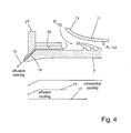
figure 4 , a further embodiment of the claimed invention is shown. Again, the effusion holes 19 are very long compared to the thickness of the liner. In this embodiment, the effusion holes 19 are bent and they also comprise a drilled part (which is at the left at the upstream end of the liner 7) and asecond part 33, which may again be manufactured by casting grooves and covering these grooves with a covering. - It is also possible to manufacture the whole liner along with the
section 33 of the effusion holes 19 and theturbulators 25 by selective laser melting. This method of manufacture comprises locally melting a powder of metal in a way that theliner 7 with its complex geometry including the effusion holes is created by locally melting the powder of metal. Selective laser melting is a method that is known to a man skilled in the art and therefore is not described in detail in this application. - In this embodiment, the
section 33 ends in longitudinal direction at the beginning of thenozzle 13. It is also possible to elongate thesection 33 until it extends into thechannel 9. - Again, there is only convective cooling of the
liner 7, which results in reduced pressure drop Ap. -
Figure 5 shows a further embodiment with a verylong effusion hole 19 compared to the local thickness of theliner 7. To be able to manufacture effusion holes 19 that are more or less parallel to asurface 35 of theliner 7 makes it necessary in some cases to raise the thickness of the liner in the upper part where effusion takes please (thebar 21 infigures 3 to 5 ).
Claims (12)
- Combustor of a gas turbine comprising a liner (7) and a cover plate (11), wherein the liner (7) and the cover plate (11) border a channel (9) for cooling air, characterized in, that at the upstream beginning of the channel (9) the cover plate (11) has the shape of a nozzle (13).
- Combustor according to claim 1, characterized in, that the liner (7) comprises effusion holes (19) and in, that a length of at least one of the effusion holes (19) is more than 1.4 times a local thickness of the liner (7).
- Combustor according to one of the foregoing claims, characterized in, that the length of at least one of the effusion holes (19) is greater than 15 mm.
- Combustor according to one of the foregoing claims, characterized in, that at least some of the effusion holes (19) are partially bordered by a groove (29) in the liner (9) and a covering (31).
- Combustor according to one of the foregoing claims, characterized in, that over a section of the effusion holes (19) their longitudinal axis is parallel to at least one surface of the liner (7).
- Combustor according to claim 5, characterized in, that in this section the liner (7) has a greater thickness than in a channel section of the liner (7).
- Combustor according to one of the foregoing claims, characterized in, that the cover plate (11) or the nozzle (13) extends in axial direction over at least one row of effusion holes (19).
- Combustor according to one of the foregoing claims, characterized in, that the rows of effusion holes (19) extend in axial direction of the liner (7) over a length of more than 5 cm, preferably more than 10 cm or more than 15 cm.
- Combustor according to one of the foregoing claims, characterized in, that the liner (7) is made by casting or by selective laser melting.
- Combustor according to claim 9, characterized in, that the effusion holes (19) are at least partially generated during the casting or the selective laser melting.
- Combustor according to one of the foregoing claims, characterized in, that the channel (9) for cooling air is annular.
- Gas turbine comprising al least one compressor, at least one combustor (2, 5) at least one turbine, characterized in, that the the at least one combustor (2, 5), is a combustor according to one of the foregoing claims.
Priority Applications (6)
| Application Number | Priority Date | Filing Date | Title |
|---|---|---|---|
| EP13180549.1A EP2837887B1 (en) | 2013-08-15 | 2013-08-15 | Combustor of a gas turbine with pressure drop optimized liner cooling |
| US14/445,413 US20150047313A1 (en) | 2013-08-15 | 2014-07-29 | Combustor of a gas turbine with pressure drop optimized liner cooling |
| RU2014133510A RU2686246C2 (en) | 2013-08-15 | 2014-08-14 | Combustor of gas turbine with pressure drop optimized liner cooling |
| KR20140105625A KR20150020131A (en) | 2013-08-15 | 2014-08-14 | Combustor of a gas turbine with pressure drop optimized liner cooling |
| JP2014165471A JP2015038350A (en) | 2013-08-15 | 2014-08-15 | Gas turbine combustor with liner cooling optimized pressure drop |
| CN201410401042.6A CN104373959A (en) | 2013-08-15 | 2014-08-15 | Combustor of a gas turbine with pressure drop optimized liner cooling |
Applications Claiming Priority (1)
| Application Number | Priority Date | Filing Date | Title |
|---|---|---|---|
| EP13180549.1A EP2837887B1 (en) | 2013-08-15 | 2013-08-15 | Combustor of a gas turbine with pressure drop optimized liner cooling |
Publications (2)
| Publication Number | Publication Date |
|---|---|
| EP2837887A1 true EP2837887A1 (en) | 2015-02-18 |
| EP2837887B1 EP2837887B1 (en) | 2019-06-12 |
Family
ID=48979662
Family Applications (1)
| Application Number | Title | Priority Date | Filing Date |
|---|---|---|---|
| EP13180549.1A Active EP2837887B1 (en) | 2013-08-15 | 2013-08-15 | Combustor of a gas turbine with pressure drop optimized liner cooling |
Country Status (6)
| Country | Link |
|---|---|
| US (1) | US20150047313A1 (en) |
| EP (1) | EP2837887B1 (en) |
| JP (1) | JP2015038350A (en) |
| KR (1) | KR20150020131A (en) |
| CN (1) | CN104373959A (en) |
| RU (1) | RU2686246C2 (en) |
Families Citing this family (7)
| Publication number | Priority date | Publication date | Assignee | Title |
|---|---|---|---|---|
| US10309652B2 (en) * | 2014-04-14 | 2019-06-04 | Siemens Energy, Inc. | Gas turbine engine combustor basket with inverted platefins |
| US20150338101A1 (en) * | 2014-05-21 | 2015-11-26 | General Electric Company | Turbomachine combustor including a combustor sleeve baffle |
| DE102015224988A1 (en) * | 2015-12-11 | 2017-06-14 | Rolls-Royce Deutschland Ltd & Co Kg | Method for assembling a combustion chamber of a gas turbine engine |
| US10286450B2 (en) * | 2016-04-27 | 2019-05-14 | General Electric Company | Method and assembly for forming components using a jacketed core |
| EP3290804A1 (en) * | 2016-08-31 | 2018-03-07 | Siemens Aktiengesellschaft | A burner with fuel and air supply incorporated in a wall of the burner |
| EP3342991B1 (en) * | 2016-12-30 | 2020-10-14 | Ansaldo Energia IP UK Limited | Baffles for cooling in a gas turbine |
| CN113091091A (en) * | 2021-05-13 | 2021-07-09 | 中国联合重型燃气轮机技术有限公司 | Combustion chamber laminate and combustion chamber |
Citations (5)
| Publication number | Priority date | Publication date | Assignee | Title |
|---|---|---|---|---|
| US4896510A (en) * | 1987-02-06 | 1990-01-30 | General Electric Company | Combustor liner cooling arrangement |
| EP1515090A1 (en) * | 2003-09-10 | 2005-03-16 | General Electric Company | Thick coated combustor liner |
| US20050056020A1 (en) * | 2003-08-26 | 2005-03-17 | Honeywell International Inc. | Tube cooled combustor |
| EP1970628A2 (en) * | 2007-03-15 | 2008-09-17 | Honeywell International Inc. | Methods of forming fan-shaped effusion holes in combustors |
| EP1983266A2 (en) * | 2007-04-17 | 2008-10-22 | General Electric Company | Methods and systems to facilitate reducing combustor pressure drops |
Family Cites Families (12)
| Publication number | Priority date | Publication date | Assignee | Title |
|---|---|---|---|---|
| US2458497A (en) * | 1945-05-05 | 1949-01-11 | Babcock & Wilcox Co | Combustion chamber |
| FR2752916B1 (en) * | 1996-09-05 | 1998-10-02 | Snecma | THERMAL PROTECTIVE SHIRT FOR TURBOREACTOR COMBUSTION CHAMBER |
| US6427446B1 (en) * | 2000-09-19 | 2002-08-06 | Power Systems Mfg., Llc | Low NOx emission combustion liner with circumferentially angled film cooling holes |
| US7363763B2 (en) * | 2003-10-23 | 2008-04-29 | United Technologies Corporation | Combustor |
| US7540156B2 (en) * | 2005-11-21 | 2009-06-02 | General Electric Company | Combustion liner for gas turbine formed of cast nickel-based superalloy |
| US7546737B2 (en) * | 2006-01-24 | 2009-06-16 | Honeywell International Inc. | Segmented effusion cooled gas turbine engine combustor |
| EP1813869A3 (en) * | 2006-01-25 | 2013-08-14 | Rolls-Royce plc | Wall elements for gas turbine engine combustors |
| US8109098B2 (en) * | 2006-05-04 | 2012-02-07 | Siemens Energy, Inc. | Combustor liner for gas turbine engine |
| RU2398160C1 (en) * | 2009-05-25 | 2010-08-27 | Открытое акционерное общество "Климов" | Gas turbine engine combustion chamber (versions) |
| US8590314B2 (en) * | 2010-04-09 | 2013-11-26 | General Electric Company | Combustor liner helical cooling apparatus |
| EP2405200A1 (en) * | 2010-07-05 | 2012-01-11 | Siemens Aktiengesellschaft | A combustion apparatus and gas turbine engine |
| US20120047895A1 (en) * | 2010-08-26 | 2012-03-01 | General Electric Company | Systems and apparatus relating to combustor cooling and operation in gas turbine engines |
-
2013
- 2013-08-15 EP EP13180549.1A patent/EP2837887B1/en active Active
-
2014
- 2014-07-29 US US14/445,413 patent/US20150047313A1/en not_active Abandoned
- 2014-08-14 RU RU2014133510A patent/RU2686246C2/en active
- 2014-08-14 KR KR20140105625A patent/KR20150020131A/en not_active Withdrawn
- 2014-08-15 CN CN201410401042.6A patent/CN104373959A/en active Pending
- 2014-08-15 JP JP2014165471A patent/JP2015038350A/en active Pending
Patent Citations (5)
| Publication number | Priority date | Publication date | Assignee | Title |
|---|---|---|---|---|
| US4896510A (en) * | 1987-02-06 | 1990-01-30 | General Electric Company | Combustor liner cooling arrangement |
| US20050056020A1 (en) * | 2003-08-26 | 2005-03-17 | Honeywell International Inc. | Tube cooled combustor |
| EP1515090A1 (en) * | 2003-09-10 | 2005-03-16 | General Electric Company | Thick coated combustor liner |
| EP1970628A2 (en) * | 2007-03-15 | 2008-09-17 | Honeywell International Inc. | Methods of forming fan-shaped effusion holes in combustors |
| EP1983266A2 (en) * | 2007-04-17 | 2008-10-22 | General Electric Company | Methods and systems to facilitate reducing combustor pressure drops |
Also Published As
| Publication number | Publication date |
|---|---|
| EP2837887B1 (en) | 2019-06-12 |
| KR20150020131A (en) | 2015-02-25 |
| RU2686246C2 (en) | 2019-04-24 |
| RU2014133510A (en) | 2016-03-10 |
| JP2015038350A (en) | 2015-02-26 |
| CN104373959A (en) | 2015-02-25 |
| US20150047313A1 (en) | 2015-02-19 |
Similar Documents
| Publication | Publication Date | Title |
|---|---|---|
| EP2837887B1 (en) | Combustor of a gas turbine with pressure drop optimized liner cooling | |
| EP2481983B1 (en) | Turbulated Aft-End liner assembly and cooling method for gas turbine combustor | |
| EP1413829B1 (en) | Combustor liner with inverted turbulators | |
| US8707708B2 (en) | 3D non-axisymmetric combustor liner | |
| EP2211105A2 (en) | Turbulated combustor aft-end liner assembly and related cooling method | |
| US20120304654A1 (en) | Combustion liner having turbulators | |
| US9038396B2 (en) | Cooling apparatus for combustor transition piece | |
| US20090120093A1 (en) | Turbulated aft-end liner assembly and cooling method | |
| US8915087B2 (en) | Methods and systems for transferring heat from a transition nozzle | |
| EP2375160A2 (en) | Angled seal cooling system | |
| CN108138583A (en) | The method of turbine components and manufacture and this turbine components of operation with air-circulation features portion | |
| JP2014009937A (en) | Transition duct for gas turbine | |
| EP1426558A2 (en) | Gas turbine transition piece with dimpled surface and cooling method for such a transition piece | |
| EP3067622B1 (en) | Combustion chamber with double wall and method of cooling the combustion chamber | |
| EP3147567B1 (en) | Single skin combustor with heat transfer enhancement | |
| CN102818286A (en) | Combustion liner and transition piece | |
| EP3494344B1 (en) | Machine component, particularly a turbomachine component, with cooling features | |
| EP3032174B1 (en) | Counter-swirl doublet combustor with plunged holes | |
| US20110255956A1 (en) | Gas turbine having cooling insert | |
| KR101842746B1 (en) | Connecting device of transition piece and turbine of gas turbine | |
| KR101842745B1 (en) | Connecting device of transition piece and turbine of gas turbine |
Legal Events
| Date | Code | Title | Description |
|---|---|---|---|
| 17P | Request for examination filed |
Effective date: 20130815 |
|
| AK | Designated contracting states |
Kind code of ref document: A1 Designated state(s): AL AT BE BG CH CY CZ DE DK EE ES FI FR GB GR HR HU IE IS IT LI LT LU LV MC MK MT NL NO PL PT RO RS SE SI SK SM TR |
|
| AX | Request for extension of the european patent |
Extension state: BA ME |
|
| PUAI | Public reference made under article 153(3) epc to a published international application that has entered the european phase |
Free format text: ORIGINAL CODE: 0009012 |
|
| RAP1 | Party data changed (applicant data changed or rights of an application transferred) |
Owner name: GENERAL ELECTRIC TECHNOLOGY GMBH |
|
| RAP1 | Party data changed (applicant data changed or rights of an application transferred) |
Owner name: ANSALDO ENERGIA SWITZERLAND AG |
|
| REG | Reference to a national code |
Ref country code: DE Ref legal event code: R079 Ref document number: 602013056438 Country of ref document: DE Free format text: PREVIOUS MAIN CLASS: F23R0003040000 Ipc: F02C0003000000 |
|
| RIC1 | Information provided on ipc code assigned before grant |
Ipc: F02C 3/00 20060101AFI20181122BHEP Ipc: F23R 3/04 20060101ALI20181122BHEP Ipc: F23R 3/06 20060101ALI20181122BHEP |
|
| GRAP | Despatch of communication of intention to grant a patent |
Free format text: ORIGINAL CODE: EPIDOSNIGR1 |
|
| STAA | Information on the status of an ep patent application or granted ep patent |
Free format text: STATUS: GRANT OF PATENT IS INTENDED |
|
| INTG | Intention to grant announced |
Effective date: 20190102 |
|
| RIN1 | Information on inventor provided before grant (corrected) |
Inventor name: SWIATEK, SLAWOMIR Inventor name: MALLM, MAURICE Inventor name: MAURER, MICHAEL THOMAS Inventor name: KONRADT, OLIVER Inventor name: BENZ, URS |
|
| GRAS | Grant fee paid |
Free format text: ORIGINAL CODE: EPIDOSNIGR3 |
|
| GRAA | (expected) grant |
Free format text: ORIGINAL CODE: 0009210 |
|
| STAA | Information on the status of an ep patent application or granted ep patent |
Free format text: STATUS: THE PATENT HAS BEEN GRANTED |
|
| AK | Designated contracting states |
Kind code of ref document: B1 Designated state(s): AL AT BE BG CH CY CZ DE DK EE ES FI FR GB GR HR HU IE IS IT LI LT LU LV MC MK MT NL NO PL PT RO RS SE SI SK SM TR |
|
| REG | Reference to a national code |
Ref country code: GB Ref legal event code: FG4D |
|
| REG | Reference to a national code |
Ref country code: CH Ref legal event code: EP |
|
| REG | Reference to a national code |
Ref country code: AT Ref legal event code: REF Ref document number: 1142838 Country of ref document: AT Kind code of ref document: T Effective date: 20190615 |
|
| REG | Reference to a national code |
Ref country code: DE Ref legal event code: R096 Ref document number: 602013056438 Country of ref document: DE |
|
| REG | Reference to a national code |
Ref country code: IE Ref legal event code: FG4D |
|
| REG | Reference to a national code |
Ref country code: NL Ref legal event code: MP Effective date: 20190612 |
|
| REG | Reference to a national code |
Ref country code: LT Ref legal event code: MG4D |
|
| PG25 | Lapsed in a contracting state [announced via postgrant information from national office to epo] |
Ref country code: LT Free format text: LAPSE BECAUSE OF FAILURE TO SUBMIT A TRANSLATION OF THE DESCRIPTION OR TO PAY THE FEE WITHIN THE PRESCRIBED TIME-LIMIT Effective date: 20190612 Ref country code: HR Free format text: LAPSE BECAUSE OF FAILURE TO SUBMIT A TRANSLATION OF THE DESCRIPTION OR TO PAY THE FEE WITHIN THE PRESCRIBED TIME-LIMIT Effective date: 20190612 Ref country code: FI Free format text: LAPSE BECAUSE OF FAILURE TO SUBMIT A TRANSLATION OF THE DESCRIPTION OR TO PAY THE FEE WITHIN THE PRESCRIBED TIME-LIMIT Effective date: 20190612 Ref country code: NO Free format text: LAPSE BECAUSE OF FAILURE TO SUBMIT A TRANSLATION OF THE DESCRIPTION OR TO PAY THE FEE WITHIN THE PRESCRIBED TIME-LIMIT Effective date: 20190912 Ref country code: SE Free format text: LAPSE BECAUSE OF FAILURE TO SUBMIT A TRANSLATION OF THE DESCRIPTION OR TO PAY THE FEE WITHIN THE PRESCRIBED TIME-LIMIT Effective date: 20190612 Ref country code: AL Free format text: LAPSE BECAUSE OF FAILURE TO SUBMIT A TRANSLATION OF THE DESCRIPTION OR TO PAY THE FEE WITHIN THE PRESCRIBED TIME-LIMIT Effective date: 20190612 |
|
| PG25 | Lapsed in a contracting state [announced via postgrant information from national office to epo] |
Ref country code: BG Free format text: LAPSE BECAUSE OF FAILURE TO SUBMIT A TRANSLATION OF THE DESCRIPTION OR TO PAY THE FEE WITHIN THE PRESCRIBED TIME-LIMIT Effective date: 20190912 Ref country code: LV Free format text: LAPSE BECAUSE OF FAILURE TO SUBMIT A TRANSLATION OF THE DESCRIPTION OR TO PAY THE FEE WITHIN THE PRESCRIBED TIME-LIMIT Effective date: 20190612 Ref country code: RS Free format text: LAPSE BECAUSE OF FAILURE TO SUBMIT A TRANSLATION OF THE DESCRIPTION OR TO PAY THE FEE WITHIN THE PRESCRIBED TIME-LIMIT Effective date: 20190612 Ref country code: GR Free format text: LAPSE BECAUSE OF FAILURE TO SUBMIT A TRANSLATION OF THE DESCRIPTION OR TO PAY THE FEE WITHIN THE PRESCRIBED TIME-LIMIT Effective date: 20190913 |
|
| REG | Reference to a national code |
Ref country code: AT Ref legal event code: MK05 Ref document number: 1142838 Country of ref document: AT Kind code of ref document: T Effective date: 20190612 |
|
| PG25 | Lapsed in a contracting state [announced via postgrant information from national office to epo] |
Ref country code: EE Free format text: LAPSE BECAUSE OF FAILURE TO SUBMIT A TRANSLATION OF THE DESCRIPTION OR TO PAY THE FEE WITHIN THE PRESCRIBED TIME-LIMIT Effective date: 20190612 Ref country code: NL Free format text: LAPSE BECAUSE OF FAILURE TO SUBMIT A TRANSLATION OF THE DESCRIPTION OR TO PAY THE FEE WITHIN THE PRESCRIBED TIME-LIMIT Effective date: 20190612 Ref country code: AT Free format text: LAPSE BECAUSE OF FAILURE TO SUBMIT A TRANSLATION OF THE DESCRIPTION OR TO PAY THE FEE WITHIN THE PRESCRIBED TIME-LIMIT Effective date: 20190612 Ref country code: CZ Free format text: LAPSE BECAUSE OF FAILURE TO SUBMIT A TRANSLATION OF THE DESCRIPTION OR TO PAY THE FEE WITHIN THE PRESCRIBED TIME-LIMIT Effective date: 20190612 Ref country code: RO Free format text: LAPSE BECAUSE OF FAILURE TO SUBMIT A TRANSLATION OF THE DESCRIPTION OR TO PAY THE FEE WITHIN THE PRESCRIBED TIME-LIMIT Effective date: 20190612 Ref country code: SK Free format text: LAPSE BECAUSE OF FAILURE TO SUBMIT A TRANSLATION OF THE DESCRIPTION OR TO PAY THE FEE WITHIN THE PRESCRIBED TIME-LIMIT Effective date: 20190612 Ref country code: PT Free format text: LAPSE BECAUSE OF FAILURE TO SUBMIT A TRANSLATION OF THE DESCRIPTION OR TO PAY THE FEE WITHIN THE PRESCRIBED TIME-LIMIT Effective date: 20191014 |
|
| PG25 | Lapsed in a contracting state [announced via postgrant information from national office to epo] |
Ref country code: SM Free format text: LAPSE BECAUSE OF FAILURE TO SUBMIT A TRANSLATION OF THE DESCRIPTION OR TO PAY THE FEE WITHIN THE PRESCRIBED TIME-LIMIT Effective date: 20190612 Ref country code: IS Free format text: LAPSE BECAUSE OF FAILURE TO SUBMIT A TRANSLATION OF THE DESCRIPTION OR TO PAY THE FEE WITHIN THE PRESCRIBED TIME-LIMIT Effective date: 20191012 Ref country code: IT Free format text: LAPSE BECAUSE OF FAILURE TO SUBMIT A TRANSLATION OF THE DESCRIPTION OR TO PAY THE FEE WITHIN THE PRESCRIBED TIME-LIMIT Effective date: 20190612 Ref country code: ES Free format text: LAPSE BECAUSE OF FAILURE TO SUBMIT A TRANSLATION OF THE DESCRIPTION OR TO PAY THE FEE WITHIN THE PRESCRIBED TIME-LIMIT Effective date: 20190612 |
|
| REG | Reference to a national code |
Ref country code: DE Ref legal event code: R097 Ref document number: 602013056438 Country of ref document: DE |
|
| PG25 | Lapsed in a contracting state [announced via postgrant information from national office to epo] |
Ref country code: TR Free format text: LAPSE BECAUSE OF FAILURE TO SUBMIT A TRANSLATION OF THE DESCRIPTION OR TO PAY THE FEE WITHIN THE PRESCRIBED TIME-LIMIT Effective date: 20190612 |
|
| PLBE | No opposition filed within time limit |
Free format text: ORIGINAL CODE: 0009261 |
|
| STAA | Information on the status of an ep patent application or granted ep patent |
Free format text: STATUS: NO OPPOSITION FILED WITHIN TIME LIMIT |
|
| PG25 | Lapsed in a contracting state [announced via postgrant information from national office to epo] |
Ref country code: DK Free format text: LAPSE BECAUSE OF FAILURE TO SUBMIT A TRANSLATION OF THE DESCRIPTION OR TO PAY THE FEE WITHIN THE PRESCRIBED TIME-LIMIT Effective date: 20190612 Ref country code: PL Free format text: LAPSE BECAUSE OF FAILURE TO SUBMIT A TRANSLATION OF THE DESCRIPTION OR TO PAY THE FEE WITHIN THE PRESCRIBED TIME-LIMIT Effective date: 20190612 |
|
| 26N | No opposition filed |
Effective date: 20200313 |
|
| PG25 | Lapsed in a contracting state [announced via postgrant information from national office to epo] |
Ref country code: LI Free format text: LAPSE BECAUSE OF NON-PAYMENT OF DUE FEES Effective date: 20190831 Ref country code: LU Free format text: LAPSE BECAUSE OF NON-PAYMENT OF DUE FEES Effective date: 20190815 Ref country code: IS Free format text: LAPSE BECAUSE OF FAILURE TO SUBMIT A TRANSLATION OF THE DESCRIPTION OR TO PAY THE FEE WITHIN THE PRESCRIBED TIME-LIMIT Effective date: 20200224 Ref country code: SI Free format text: LAPSE BECAUSE OF FAILURE TO SUBMIT A TRANSLATION OF THE DESCRIPTION OR TO PAY THE FEE WITHIN THE PRESCRIBED TIME-LIMIT Effective date: 20190612 Ref country code: CH Free format text: LAPSE BECAUSE OF NON-PAYMENT OF DUE FEES Effective date: 20190831 Ref country code: MC Free format text: LAPSE BECAUSE OF FAILURE TO SUBMIT A TRANSLATION OF THE DESCRIPTION OR TO PAY THE FEE WITHIN THE PRESCRIBED TIME-LIMIT Effective date: 20190612 |
|
| REG | Reference to a national code |
Ref country code: BE Ref legal event code: MM Effective date: 20190831 |
|
| PG2D | Information on lapse in contracting state deleted |
Ref country code: IS |
|
| PG25 | Lapsed in a contracting state [announced via postgrant information from national office to epo] |
Ref country code: FR Free format text: LAPSE BECAUSE OF NON-PAYMENT OF DUE FEES Effective date: 20190831 Ref country code: IE Free format text: LAPSE BECAUSE OF NON-PAYMENT OF DUE FEES Effective date: 20190815 |
|
| PG25 | Lapsed in a contracting state [announced via postgrant information from national office to epo] |
Ref country code: BE Free format text: LAPSE BECAUSE OF NON-PAYMENT OF DUE FEES Effective date: 20190831 |
|
| GBPC | Gb: european patent ceased through non-payment of renewal fee |
Effective date: 20190912 |
|
| PG25 | Lapsed in a contracting state [announced via postgrant information from national office to epo] |
Ref country code: GB Free format text: LAPSE BECAUSE OF NON-PAYMENT OF DUE FEES Effective date: 20190912 |
|
| PG25 | Lapsed in a contracting state [announced via postgrant information from national office to epo] |
Ref country code: CY Free format text: LAPSE BECAUSE OF FAILURE TO SUBMIT A TRANSLATION OF THE DESCRIPTION OR TO PAY THE FEE WITHIN THE PRESCRIBED TIME-LIMIT Effective date: 20190612 |
|
| PG25 | Lapsed in a contracting state [announced via postgrant information from national office to epo] |
Ref country code: HU Free format text: LAPSE BECAUSE OF FAILURE TO SUBMIT A TRANSLATION OF THE DESCRIPTION OR TO PAY THE FEE WITHIN THE PRESCRIBED TIME-LIMIT; INVALID AB INITIO Effective date: 20130815 Ref country code: MT Free format text: LAPSE BECAUSE OF FAILURE TO SUBMIT A TRANSLATION OF THE DESCRIPTION OR TO PAY THE FEE WITHIN THE PRESCRIBED TIME-LIMIT Effective date: 20190612 |
|
| PG25 | Lapsed in a contracting state [announced via postgrant information from national office to epo] |
Ref country code: MK Free format text: LAPSE BECAUSE OF FAILURE TO SUBMIT A TRANSLATION OF THE DESCRIPTION OR TO PAY THE FEE WITHIN THE PRESCRIBED TIME-LIMIT Effective date: 20190612 |
|
| P01 | Opt-out of the competence of the unified patent court (upc) registered |
Effective date: 20240430 |
|
| PGFP | Annual fee paid to national office [announced via postgrant information from national office to epo] |
Ref country code: DE Payment date: 20250819 Year of fee payment: 13 |