EP2837869A1 - Hose coupling, hose part and hose and pump system provided therewith, and method for coupling hose parts - Google Patents
Hose coupling, hose part and hose and pump system provided therewith, and method for coupling hose parts Download PDFInfo
- Publication number
- EP2837869A1 EP2837869A1 EP14180550.7A EP14180550A EP2837869A1 EP 2837869 A1 EP2837869 A1 EP 2837869A1 EP 14180550 A EP14180550 A EP 14180550A EP 2837869 A1 EP2837869 A1 EP 2837869A1
- Authority
- EP
- European Patent Office
- Prior art keywords
- hose
- coupling
- parts
- eyelet
- hose part
- Prior art date
- Legal status (The legal status is an assumption and is not a legal conclusion. Google has not performed a legal analysis and makes no representation as to the accuracy of the status listed.)
- Granted
Links
Images



Classifications
-
- F—MECHANICAL ENGINEERING; LIGHTING; HEATING; WEAPONS; BLASTING
- F16—ENGINEERING ELEMENTS AND UNITS; GENERAL MEASURES FOR PRODUCING AND MAINTAINING EFFECTIVE FUNCTIONING OF MACHINES OR INSTALLATIONS; THERMAL INSULATION IN GENERAL
- F16L—PIPES; JOINTS OR FITTINGS FOR PIPES; SUPPORTS FOR PIPES, CABLES OR PROTECTIVE TUBING; MEANS FOR THERMAL INSULATION IN GENERAL
- F16L31/00—Arrangements for connecting hoses to one another or to flexible sleeves
-
- E—FIXED CONSTRUCTIONS
- E02—HYDRAULIC ENGINEERING; FOUNDATIONS; SOIL SHIFTING
- E02B—HYDRAULIC ENGINEERING
- E02B3/00—Engineering works in connection with control or use of streams, rivers, coasts, or other marine sites; Sealings or joints for engineering works in general
- E02B3/04—Structures or apparatus for, or methods of, protecting banks, coasts, or harbours
- E02B3/10—Dams; Dykes; Sluice ways or other structures for dykes, dams, or the like
Definitions
- the present invention relates to a hose coupling for coupling hose parts.
- hose parts relate particularly to hose parts for a pump system for pumping away excess water, for instance in the case of flooding.
- hose couplings for hose parts known in practice use is made of hooks and eyelets which are provided on the outer ends of two hose parts to be mutually connected. These hooks and eyelets have to be connected to each other. It is found difficult in practice to connect all hooks and eyelets to each other in correct manner without the risk of detachment, of outer ends or edges of the hose parts being wholly or partially folded over, resulting in an increased risk of leakage and of the hose parts not fully connecting to each other. In addition, mutually coupling hose parts is found to be relatively time-consuming.
- the object of the present invention is to provide a hose coupling which obviates or reduces the above stated problems.
- the hose coupling according to the present invention comprising:
- Providing an eyelet on an outer end of a first hose part and a coupling element on an outer end of a second hose part makes it possible to connect the two outer ends of the individual hose parts to each other by coupling eyelet and coupling element.
- Providing a guide achieves that the guide can first be threaded through an eyelet.
- the coupling element can then also be pulled through the eyelet by exerting force on the guide.
- the coupling element can hereby be threaded through the eyelet in effective manner.
- the coupling element is provided as a hook or bracket.
- the coupling is used to connect individual hose parts in order to pump away excess water, for instance in the case of flooding.
- a hose part is for instance provided here with a length of about 5 metres, with a diameter of about 30 cm in use.
- the guide comprises a cord.
- a cord is understood to mean an element with which a pulling force can be exerted on the coupling element, including a rope, strip, rod, lead etc.
- the guide is for instance manufactured from a flexible material of for instance polyester or other plastic, or natural materials such as cotton.
- the coupling further comprises a tensioning belt for fastening the hose coupling in a connected state.
- a tensioning belt for fastening the hose coupling in a connected state.
- the coupling further comprises an elastic band arranged on the second hose part with the coupling elements.
- An improved seal is realized by providing an elastic band.
- the elastic band is preferably embodied as a foam band.
- the coupling further comprises a substantially non-elastic band arranged on the first hose part.
- the band prevents/reduces expansion in diameter of the hose during use resulting from the liquid pressure employed.
- the non-elastic band is preferably positioned on the first hose part such that in a connected position during use it lies substantially at a position, directly or indirectly, around the elastic band on the second hose part. The fixation at the position of the improved seal is hereby further optimized.
- the coupling further comprises a stretchable ring or string arranged on the second hose part.
- a relative positioning of the two hose parts which is optimal in use is brought about by providing a stretchable ring or string. Leakage is hereby further prevented.
- the present invention further relates to a hose part, hose and/or a pump system provided with a hose coupling as described above.
- Such a hose part, hose and/or pump unit provides the same effects and advantages as described above in respect of the hose coupling.
- the hose part or the hose according to the invention is provided on a first outer end with a number of eyelets and on a second outer end with a number of coupling elements connectable to the eyelets.
- the number of eyelets and coupling elements of the hose part or hose according to the invention lies between 5 and 30, and preferably amounts to about 12-25. It has been found that such a number on the one hand provides a manageable coupling and on the other results in a coupling which operates in practice and provides sufficient sealing.
- the hose part or the hose is provided on an outer end with one, preferably at least two, incisions extending substantially in longitudinal direction of the hose part or the hose. With such incisions a flap on the outer end of a hose part can be folded back during attachment thereof to another hose part. It has been found that hose parts can hereby be coupled to each other in more efficient manner. The speed of coupling and uncoupling of hose parts can hereby be increased. One or more flaps which can cover the incisions are optionally provided. An additional protection against leakage is hereby provided. Additionally or alternatively provided over the periphery of the hose part is a sealing ring which imparts a degree of clamping relative to the hose part for coupling, and thereby realizes a sealing.
- the invention further also relates to a method for coupling a hose, comprising the steps of:
- Such a method provides the same effects and advantages as described above for the hose coupling and the hose part, the hose and/or the pump unit provided therewith.
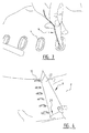
- Hose coupling 2 ( Figure 1 ) comprises eyelets or openings 4 in outer end 6 of first hose part 8.
- Coupling 2 further comprises hooks 10 on outer end 12 of second hose part 14 on which guides 16 are arranged. Hooks 10 are fixed in the shown coupled position with tensioning belt 18.
- outer end 6 of first hose part 8 is provided with incisions 20.
- the number of incisions 20 amounts to two.
- Outer end 6 is divided into flaps 22 by incisions 20.
- Hose system or pump system 24 ( Figures 5-6 ) consists of a number of coupled hose parts 8, 14. Water flows via outlet 26 to an external reservoir or drain. Hose 28 is formed by connecting a number of hose parts 8, 14 using coupling 2.
- outer end 12 of the, during use inner, second hose part 14 is provided with ring 30 which imparts a form-retention to outer end 12 and realizes a seal against the inner wall of outer end 6 of first hose part 8.
- Ring 30 in the shown embodiment is provided as a string of a material with a diameter of about 10 mm and is provided all around the outer end of hose part 14 on which hooks or brackets 10 are arranged.
- Inner hose part 14 is further provided in the shown embodiment with an elastic band 34 of a foam material at a distance of about 70 mm from hook or brackets 10.
- an elastic band 34 of a foam material at a distance of about 70 mm from hook or brackets 10.
- non-elastic band 32 against which elastic band 34 will press during use as a result of the liquid pressure.
- a good seal is hereby provided between hose parts 10, 14.
- Hose or pump system 24 is installed for the purpose of draining excess water. It is customary in practice to have hose 28 available in already coupled state and to adjust its length by uncoupling coupling 2. After draining of the excess water the uncoupled hose parts 8, 14 are stored away again coupled in the above discussed manner using coupling 2. It is of course also possible to couple the hose parts to the correct length using coupling 2 prior to the draining.
Landscapes
- Engineering & Computer Science (AREA)
- General Engineering & Computer Science (AREA)
- Mechanical Engineering (AREA)
- Joints That Cut Off Fluids, And Hose Joints (AREA)
Abstract
- an eyelet (4) provided on a first hose part (8);
- a coupling element (10) provided on a second hose part (14);
- a guide (16) which is connected to the coupling element (10) and which is configured to be threaded through the eyelet (4) such that the coupling element (10) can then be threaded through the eyelet (4) for the purpose of connecting the first and second hose parts (8, 14).
Description
- The present invention relates to a hose coupling for coupling hose parts. Such hose parts relate particularly to hose parts for a pump system for pumping away excess water, for instance in the case of flooding.
- In the case of hose couplings for hose parts known in practice use is made of hooks and eyelets which are provided on the outer ends of two hose parts to be mutually connected. These hooks and eyelets have to be connected to each other. It is found difficult in practice to connect all hooks and eyelets to each other in correct manner without the risk of detachment, of outer ends or edges of the hose parts being wholly or partially folded over, resulting in an increased risk of leakage and of the hose parts not fully connecting to each other. In addition, mutually coupling hose parts is found to be relatively time-consuming.
- The object of the present invention is to provide a hose coupling which obviates or reduces the above stated problems.
- This object is achieved with the hose coupling according to the present invention, the hose coupling for mutually coupling hose parts comprising:
- an eyelet provided on a first hose part;
- a coupling element provided on a second hose part;
- a guide which is connected to the coupling element and which is configured to be threaded through the eyelet such that the coupling element can then be threaded through the eyelet for the purpose of connecting the first and second hose parts.
- Providing an eyelet on an outer end of a first hose part and a coupling element on an outer end of a second hose part makes it possible to connect the two outer ends of the individual hose parts to each other by coupling eyelet and coupling element. Providing a guide achieves that the guide can first be threaded through an eyelet. The coupling element can then also be pulled through the eyelet by exerting force on the guide. The coupling element can hereby be threaded through the eyelet in effective manner. In a currently preferred embodiment the coupling element is provided as a hook or bracket.
- In an intended application the coupling is used to connect individual hose parts in order to pump away excess water, for instance in the case of flooding. A hose part is for instance provided here with a length of about 5 metres, with a diameter of about 30 cm in use. An operating pressure of about 1-4 bar, usually about 2 bar, is usually employed in practice. It has been found that the coupling according to the invention provides in effective manner a system which is practical and flexible in use.
- In a currently preferred embodiment according to the invention the guide comprises a cord. In the context of the invention a cord is understood to mean an element with which a pulling force can be exerted on the coupling element, including a rope, strip, rod, lead etc. The guide is for instance manufactured from a flexible material of for instance polyester or other plastic, or natural materials such as cotton.
- In a further currently preferred embodiment according to the invention the coupling further comprises a tensioning belt for fastening the hose coupling in a connected state. Using such a tensioning belt the coupling can be fixed in simple manner in the connected state, in which the coupling elements have been drawn through the eyelets, and will not become detached during use.
- In a further currently preferred embodiment according to the invention the coupling further comprises an elastic band arranged on the second hose part with the coupling elements.
- An improved seal is realized by providing an elastic band. During use the liquid pressure in the hose presses the second, inner hose part outward against the first hose part, which is provided with the eyelets. Providing the elastic band on the outer side of the second hose part provides an improved seal between the hose parts so that less leakage will occur at the transition between the hose parts. The elastic band is preferably embodied as a foam band.
- In a further currently preferred embodiment according to the invention the coupling further comprises a substantially non-elastic band arranged on the first hose part.
- Providing a substantially non-elastic band, preferably on the outer side of the first hose part in which the eyelets are arranged, effects a further mutual fixation of the two hose parts. The band prevents/reduces expansion in diameter of the hose during use resulting from the liquid pressure employed. The non-elastic band is preferably positioned on the first hose part such that in a connected position during use it lies substantially at a position, directly or indirectly, around the elastic band on the second hose part. The fixation at the position of the improved seal is hereby further optimized.
- In a further currently preferred embodiment according to the invention the coupling further comprises a stretchable ring or string arranged on the second hose part.
- A relative positioning of the two hose parts which is optimal in use is brought about by providing a stretchable ring or string. Leakage is hereby further prevented.
- The present invention further relates to a hose part, hose and/or a pump system provided with a hose coupling as described above.
- Such a hose part, hose and/or pump unit provides the same effects and advantages as described above in respect of the hose coupling.
- In a currently preferred embodiment the hose part or the hose according to the invention is provided on a first outer end with a number of eyelets and on a second outer end with a number of coupling elements connectable to the eyelets.
- In a currently preferred embodiment the number of eyelets and coupling elements of the hose part or hose according to the invention lies between 5 and 30, and preferably amounts to about 12-25. It has been found that such a number on the one hand provides a manageable coupling and on the other results in a coupling which operates in practice and provides sufficient sealing.
- In a further currently preferred embodiment the hose part or the hose is provided on an outer end with one, preferably at least two, incisions extending substantially in longitudinal direction of the hose part or the hose. With such incisions a flap on the outer end of a hose part can be folded back during attachment thereof to another hose part. It has been found that hose parts can hereby be coupled to each other in more efficient manner. The speed of coupling and uncoupling of hose parts can hereby be increased. One or more flaps which can cover the incisions are optionally provided. An additional protection against leakage is hereby provided. Additionally or alternatively provided over the periphery of the hose part is a sealing ring which imparts a degree of clamping relative to the hose part for coupling, and thereby realizes a sealing.
- Although the incisions can also be applied individually to any type of coupling, it has been found that, when applied in combination with the hose coupling according to the invention, hose parts can be coupled in the most effective manner, wherein sufficient sealing against leakage is realized.
- The invention further also relates to a method for coupling a hose, comprising the steps of:
- providing a hose coupling with hose parts according to one or more of the foregoing claims;
- threading through an eyelet of a first hose part a guide connected to a coupling element of a second hose part;
- threading the coupling element through the eyelet using the guide; and
- fastening the coupling elements such that they remain fixed through the eyelet and couple the first and second hose parts.
- Such a method provides the same effects and advantages as described above for the hose coupling and the hose part, the hose and/or the pump unit provided therewith.
- Further advantages, features and details of the invention are elucidated on the basis of the preferred embodiments thereof, wherein reference is made to the accompanying drawings, in which:
-
figure 1 shows a view of a hose coupling according to the invention; -
figures 2-3 show a view of the realization of the coupling offigure 1 ; -
figure 4 shows a view of an incision according to the invention; -
figures 5-6 show views of a system according to the invention; and -
figure 7 shows a view of the hose coupling with elastic and non-elastic bands. - Hose coupling 2 (
Figure 1 ) comprises eyelets oropenings 4 inouter end 6 offirst hose part 8. Coupling 2 further compriseshooks 10 onouter end 12 ofsecond hose part 14 on whichguides 16 are arranged.Hooks 10 are fixed in the shown coupled position with tensioningbelt 18. - For the purpose of realizing coupling 2 (
Figures 2-3 ) the secondflexible hose part 14 is pressed together and pushed intoouter end 6 offirst hose part 8.Guides 16 are then threaded throughopenings 4 and tightened untilhooks 10 protrude throughopenings 4. Tensioningbelt 18 can then be arranged. - In a possible embodiment (
Figure 4 )outer end 6 offirst hose part 8 is provided withincisions 20. In the shown embodiment the number ofincisions 20 amounts to two.Outer end 6 is divided intoflaps 22 byincisions 20. - Hose system or pump system 24 (
Figures 5-6 ) consists of a number of coupledhose parts outlet 26 to an external reservoir or drain.Hose 28 is formed by connecting a number ofhose parts - In the shown embodiment
outer end 12 of the, during use inner,second hose part 14 is provided withring 30 which imparts a form-retention toouter end 12 and realizes a seal against the inner wall ofouter end 6 offirst hose part 8. - Ring 30 (
Figure 7 ) in the shown embodiment is provided as a string of a material with a diameter of about 10 mm and is provided all around the outer end ofhose part 14 on which hooks orbrackets 10 are arranged.Inner hose part 14 is further provided in the shown embodiment with anelastic band 34 of a foam material at a distance of about 70 mm from hook orbrackets 10. Provided in the shown embodiment onouter hose part 8 isnon-elastic band 32 against whichelastic band 34 will press during use as a result of the liquid pressure. A good seal is hereby provided betweenhose parts - Hose or
pump system 24 is installed for the purpose of draining excess water. It is customary in practice to havehose 28 available in already coupled state and to adjust its length by uncoupling coupling 2. After draining of the excess water the uncoupledhose parts - The present invention is by no means limited to the above described embodiments thereof. The rights sought are defined by the following claims, within the scope of which many modifications can be envisaged. It is thus possible to provide
hose parts incisions 20 for further sealing of the latter as complement to sealingring 30.
Claims (13)
- Hose coupling for mutually coupling hose parts comprising:- an eyelet provided on a first hose part;- a coupling element provided on a second hose part;- a guide which is connected to the coupling element and which is configured to be threaded through the eyelet such that the coupling element can then be threaded through the eyelet for the purpose of connecting the first and second hose parts.
- Hose coupling as claimed in claim 1, wherein the guide comprises a cord.
- Hose coupling as claimed in claim 1 or 2, further comprising a tensioning belt for fixing the hose coupling in a connected state.
- Hose coupling as claimed in claim 1, 2 or 3, further comprising an elastic band arranged on the second hose part with the coupling elements.
- Hose coupling as claimed in one or more of the foregoing claims, further comprising a substantially non-elastic band arranged on the first hose part.
- Hose coupling as claimed in claim 5, to the extent dependent on claim 4, wherein the non-elastic band is positioned on the first hose part such that during use it lies around the elastic band arranged on the second hose part.
- Hose coupling as claimed in one or more of the foregoing claims, further comprising a stretchable ring or string arranged on the second hose part.
- Hose part or hose provided with a hose coupling as claimed in one or more of the foregoing claims.
- Hose part or hose as claimed in claim 8, wherein a hose part is provided on a first outer end with a number of eyelets and is provided on a second outer end with a number of coupling elements.
- Hose part or hose as claimed in claim 9, wherein the number of eyelets and coupling elements lies between 5 and 30, and preferably amounts to about 12-25.
- Hose part or hose as claimed in claim 8, 9 or 10, wherein the hose part or the hose is provided on an outer end with one, preferably at least two, incisions extending substantially in longitudinal direction of the hose part or the hose.
- Pump unit provided with a hose coupling and/or hose as claimed in one or more of the foregoing claims.
- Method for coupling hose parts, comprising the steps of:- providing a hose coupling with hose parts as claimed in one or more of the foregoing claims;- threading through an eyelet of a first hose part a guide connected to a coupling element of a second hose part;- threading the coupling element through the eyelet using the guide; and- fastening the coupling elements such that they remain fixed through the eyelet and couple the first and second hose parts.
Applications Claiming Priority (1)
| Application Number | Priority Date | Filing Date | Title |
|---|---|---|---|
| NL2011302 | 2013-08-14 |
Publications (3)
| Publication Number | Publication Date |
|---|---|
| EP2837869A1 true EP2837869A1 (en) | 2015-02-18 |
| EP2837869B1 EP2837869B1 (en) | 2016-07-27 |
| EP2837869B8 EP2837869B8 (en) | 2025-09-24 |
Family
ID=51357726
Family Applications (1)
| Application Number | Title | Priority Date | Filing Date |
|---|---|---|---|
| EP14180550.7A Active EP2837869B8 (en) | 2013-08-14 | 2014-08-11 | Hose coupling, hose part and hose and pump system provided therewith, and method for coupling hose parts |
Country Status (1)
| Country | Link |
|---|---|
| EP (1) | EP2837869B8 (en) |
Families Citing this family (3)
| Publication number | Priority date | Publication date | Assignee | Title |
|---|---|---|---|---|
| NL2040527B1 (en) | 2024-10-31 | 2026-06-04 | Hytrans Beheer B V | METHOD, ASSEMBLY OF HOSE SECTION AND TOOL, AND PUMP SYSTEM FOR PUMPING A LIQUID |
| NL2038977B1 (en) | 2024-10-31 | 2026-06-04 | Hytrans Beheer B V | HOSE SECTION AND PUMP SYSTEM FOR PUMPING A LIQUID, AND THE PROCEDURE FOR DOING SO. |
| WO2026095792A1 (en) | 2024-10-31 | 2026-05-07 | Hytrans Beheer B.V. | Method, assembly of hose part and tool, and pump system for pumping a liquid |
Citations (4)
| Publication number | Priority date | Publication date | Assignee | Title |
|---|---|---|---|---|
| DE2510250A1 (en) * | 1975-03-08 | 1976-09-16 | Ruhrkunststoff Gmbh | Ducting line for ventilating air - has laced joint between two ducts sandwiched between internal hose skirt and external sleeve |
| GB1576858A (en) * | 1977-04-23 | 1980-10-15 | Oldorid Kunstoffe Gmbh | Air-conditioning duct in particulat for mine and tunnel workings |
| DE10038592A1 (en) * | 2000-08-08 | 2002-02-28 | Gse Lining Technology Gmbh | System for temporary protection against flood waters comprises at least one watertight hose-like flexible body which in empty state is transported to its application site and is filled there with water |
| FR2919910A1 (en) * | 2007-08-06 | 2009-02-13 | Sigma Vyzkumny A Vyv Ustav Sro | Liquid e.g. water, transporting system, has main structural elements equipped with final parts of model identical to model of pipe sockets of flattenable pipe element and with flanges provided with rear conical surfaces |
-
2014
- 2014-08-11 EP EP14180550.7A patent/EP2837869B8/en active Active
Patent Citations (4)
| Publication number | Priority date | Publication date | Assignee | Title |
|---|---|---|---|---|
| DE2510250A1 (en) * | 1975-03-08 | 1976-09-16 | Ruhrkunststoff Gmbh | Ducting line for ventilating air - has laced joint between two ducts sandwiched between internal hose skirt and external sleeve |
| GB1576858A (en) * | 1977-04-23 | 1980-10-15 | Oldorid Kunstoffe Gmbh | Air-conditioning duct in particulat for mine and tunnel workings |
| DE10038592A1 (en) * | 2000-08-08 | 2002-02-28 | Gse Lining Technology Gmbh | System for temporary protection against flood waters comprises at least one watertight hose-like flexible body which in empty state is transported to its application site and is filled there with water |
| FR2919910A1 (en) * | 2007-08-06 | 2009-02-13 | Sigma Vyzkumny A Vyv Ustav Sro | Liquid e.g. water, transporting system, has main structural elements equipped with final parts of model identical to model of pipe sockets of flattenable pipe element and with flanges provided with rear conical surfaces |
Also Published As
| Publication number | Publication date |
|---|---|
| EP2837869B1 (en) | 2016-07-27 |
| EP2837869B8 (en) | 2025-09-24 |
Similar Documents
| Publication | Publication Date | Title |
|---|---|---|
| RU2463507C2 (en) | Beak-type shutoff valve with curved and elastically shifted gate | |
| EP2837869B1 (en) | Hose coupling, hose part and hose and pump system provided therewith, and method for coupling hose parts | |
| US20100282351A1 (en) | Pipe-lining material and pipeline lining method | |
| RU2012148599A (en) | EXTENDABLE AND COMPRESSIBLE HOSE | |
| UA96522C2 (en) | Machine for linen treatment (variants) | |
| JP4989203B2 (en) | Lining material and pipeline lining method | |
| US10788155B2 (en) | Sealing device for sealing a leak in a pipe | |
| US9523449B2 (en) | Pipe coupling | |
| GB2485249A (en) | A device to repair a kinked hose pipe | |
| JP5086833B2 (en) | Lining material | |
| AU2016327733A1 (en) | Leakage protection apparatus | |
| CN206159662U (en) | From tightening up clamp | |
| JP2019092447A (en) | Binder and milking unit | |
| PL3885628T3 (en) | Flexible hose with a non-demountable connection system for connecting the flexible hose to a hydraulic device | |
| RU2327076C1 (en) | Flexible armoured hose | |
| CN205198072U (en) | Compression hemostasis belt | |
| EP2603725B1 (en) | Fitting assembly | |
| JP5607099B2 (en) | Lining material and pipeline lining method | |
| CN103999738B (en) | Irrigation plastic hose and manufacture craft thereof | |
| CN218076118U (en) | Fire hose joint fixing structure | |
| CN207584205U (en) | A kind of multilayer high-performance water pipe | |
| CN204062226U (en) | A kind of conduit assembly | |
| EP1955640B1 (en) | Improved water stop device | |
| CN214206660U (en) | Water belt for watering land | |
| CN105864542B (en) | Flexible sealing fire-fighting attachment device and its application method |
Legal Events
| Date | Code | Title | Description |
|---|---|---|---|
| 17P | Request for examination filed |
Effective date: 20140811 |
|
| AK | Designated contracting states |
Kind code of ref document: A1 Designated state(s): AL AT BE BG CH CY CZ DE DK EE ES FI FR GB GR HR HU IE IS IT LI LT LU LV MC MK MT NL NO PL PT RO RS SE SI SK SM TR |
|
| AX | Request for extension of the european patent |
Extension state: BA ME |
|
| PUAI | Public reference made under article 153(3) epc to a published international application that has entered the european phase |
Free format text: ORIGINAL CODE: 0009012 |
|
| R17P | Request for examination filed (corrected) |
Effective date: 20150812 |
|
| RBV | Designated contracting states (corrected) |
Designated state(s): AL AT BE BG CH CY CZ DE DK EE ES FI FR GB GR HR HU IE IS IT LI LT LU LV MC MK MT NL NO PL PT RO RS SE SI SK SM TR |
|
| GRAP | Despatch of communication of intention to grant a patent |
Free format text: ORIGINAL CODE: EPIDOSNIGR1 |
|
| RIC1 | Information provided on ipc code assigned before grant |
Ipc: A62C 33/04 20060101ALN20160223BHEP Ipc: F16L 31/00 20060101AFI20160223BHEP Ipc: E02B 3/10 20060101ALN20160223BHEP |
|
| RIC1 | Information provided on ipc code assigned before grant |
Ipc: F16L 31/00 20060101AFI20160302BHEP Ipc: A62C 33/04 20060101ALN20160302BHEP Ipc: E02B 3/10 20060101ALN20160302BHEP |
|
| INTG | Intention to grant announced |
Effective date: 20160324 |
|
| GRAS | Grant fee paid |
Free format text: ORIGINAL CODE: EPIDOSNIGR3 |
|
| GRAA | (expected) grant |
Free format text: ORIGINAL CODE: 0009210 |
|
| AK | Designated contracting states |
Kind code of ref document: B1 Designated state(s): AL AT BE BG CH CY CZ DE DK EE ES FI FR GB GR HR HU IE IS IT LI LT LU LV MC MK MT NL NO PL PT RO RS SE SI SK SM TR |
|
| REG | Reference to a national code |
Ref country code: GB Ref legal event code: FG4D |
|
| REG | Reference to a national code |
Ref country code: CH Ref legal event code: EP |
|
| REG | Reference to a national code |
Ref country code: AT Ref legal event code: REF Ref document number: 816093 Country of ref document: AT Kind code of ref document: T Effective date: 20160815 Ref country code: CH Ref legal event code: NV Representative=s name: ARNOLD AND SIEDSMA AG, CH |
|
| REG | Reference to a national code |
Ref country code: IE Ref legal event code: FG4D |
|
| REG | Reference to a national code |
Ref country code: FR Ref legal event code: PLFP Year of fee payment: 3 |
|
| REG | Reference to a national code |
Ref country code: DE Ref legal event code: R096 Ref document number: 602014002853 Country of ref document: DE |
|
| REG | Reference to a national code |
Ref country code: NL Ref legal event code: FP |
|
| REG | Reference to a national code |
Ref country code: LT Ref legal event code: MG4D |
|
| REG | Reference to a national code |
Ref country code: AT Ref legal event code: MK05 Ref document number: 816093 Country of ref document: AT Kind code of ref document: T Effective date: 20160727 |
|
| PG25 | Lapsed in a contracting state [announced via postgrant information from national office to epo] |
Ref country code: IS Free format text: LAPSE BECAUSE OF FAILURE TO SUBMIT A TRANSLATION OF THE DESCRIPTION OR TO PAY THE FEE WITHIN THE PRESCRIBED TIME-LIMIT Effective date: 20161127 Ref country code: IT Free format text: LAPSE BECAUSE OF FAILURE TO SUBMIT A TRANSLATION OF THE DESCRIPTION OR TO PAY THE FEE WITHIN THE PRESCRIBED TIME-LIMIT Effective date: 20160727 Ref country code: FI Free format text: LAPSE BECAUSE OF FAILURE TO SUBMIT A TRANSLATION OF THE DESCRIPTION OR TO PAY THE FEE WITHIN THE PRESCRIBED TIME-LIMIT Effective date: 20160727 Ref country code: HR Free format text: LAPSE BECAUSE OF FAILURE TO SUBMIT A TRANSLATION OF THE DESCRIPTION OR TO PAY THE FEE WITHIN THE PRESCRIBED TIME-LIMIT Effective date: 20160727 Ref country code: NO Free format text: LAPSE BECAUSE OF FAILURE TO SUBMIT A TRANSLATION OF THE DESCRIPTION OR TO PAY THE FEE WITHIN THE PRESCRIBED TIME-LIMIT Effective date: 20161027 Ref country code: RS Free format text: LAPSE BECAUSE OF FAILURE TO SUBMIT A TRANSLATION OF THE DESCRIPTION OR TO PAY THE FEE WITHIN THE PRESCRIBED TIME-LIMIT Effective date: 20160727 Ref country code: LT Free format text: LAPSE BECAUSE OF FAILURE TO SUBMIT A TRANSLATION OF THE DESCRIPTION OR TO PAY THE FEE WITHIN THE PRESCRIBED TIME-LIMIT Effective date: 20160727 |
|
| PG25 | Lapsed in a contracting state [announced via postgrant information from national office to epo] |
Ref country code: LV Free format text: LAPSE BECAUSE OF FAILURE TO SUBMIT A TRANSLATION OF THE DESCRIPTION OR TO PAY THE FEE WITHIN THE PRESCRIBED TIME-LIMIT Effective date: 20160727 Ref country code: ES Free format text: LAPSE BECAUSE OF FAILURE TO SUBMIT A TRANSLATION OF THE DESCRIPTION OR TO PAY THE FEE WITHIN THE PRESCRIBED TIME-LIMIT Effective date: 20160727 Ref country code: PT Free format text: LAPSE BECAUSE OF FAILURE TO SUBMIT A TRANSLATION OF THE DESCRIPTION OR TO PAY THE FEE WITHIN THE PRESCRIBED TIME-LIMIT Effective date: 20161128 Ref country code: SE Free format text: LAPSE BECAUSE OF FAILURE TO SUBMIT A TRANSLATION OF THE DESCRIPTION OR TO PAY THE FEE WITHIN THE PRESCRIBED TIME-LIMIT Effective date: 20160727 Ref country code: PL Free format text: LAPSE BECAUSE OF FAILURE TO SUBMIT A TRANSLATION OF THE DESCRIPTION OR TO PAY THE FEE WITHIN THE PRESCRIBED TIME-LIMIT Effective date: 20160727 Ref country code: AT Free format text: LAPSE BECAUSE OF FAILURE TO SUBMIT A TRANSLATION OF THE DESCRIPTION OR TO PAY THE FEE WITHIN THE PRESCRIBED TIME-LIMIT Effective date: 20160727 Ref country code: GR Free format text: LAPSE BECAUSE OF FAILURE TO SUBMIT A TRANSLATION OF THE DESCRIPTION OR TO PAY THE FEE WITHIN THE PRESCRIBED TIME-LIMIT Effective date: 20161028 |
|
| PG25 | Lapsed in a contracting state [announced via postgrant information from national office to epo] |
Ref country code: RO Free format text: LAPSE BECAUSE OF FAILURE TO SUBMIT A TRANSLATION OF THE DESCRIPTION OR TO PAY THE FEE WITHIN THE PRESCRIBED TIME-LIMIT Effective date: 20160727 Ref country code: EE Free format text: LAPSE BECAUSE OF FAILURE TO SUBMIT A TRANSLATION OF THE DESCRIPTION OR TO PAY THE FEE WITHIN THE PRESCRIBED TIME-LIMIT Effective date: 20160727 Ref country code: MC Free format text: LAPSE BECAUSE OF FAILURE TO SUBMIT A TRANSLATION OF THE DESCRIPTION OR TO PAY THE FEE WITHIN THE PRESCRIBED TIME-LIMIT Effective date: 20160727 |
|
| REG | Reference to a national code |
Ref country code: DE Ref legal event code: R097 Ref document number: 602014002853 Country of ref document: DE |
|
| PG25 | Lapsed in a contracting state [announced via postgrant information from national office to epo] |
Ref country code: SK Free format text: LAPSE BECAUSE OF FAILURE TO SUBMIT A TRANSLATION OF THE DESCRIPTION OR TO PAY THE FEE WITHIN THE PRESCRIBED TIME-LIMIT Effective date: 20160727 Ref country code: DK Free format text: LAPSE BECAUSE OF FAILURE TO SUBMIT A TRANSLATION OF THE DESCRIPTION OR TO PAY THE FEE WITHIN THE PRESCRIBED TIME-LIMIT Effective date: 20160727 Ref country code: BG Free format text: LAPSE BECAUSE OF FAILURE TO SUBMIT A TRANSLATION OF THE DESCRIPTION OR TO PAY THE FEE WITHIN THE PRESCRIBED TIME-LIMIT Effective date: 20161027 Ref country code: SM Free format text: LAPSE BECAUSE OF FAILURE TO SUBMIT A TRANSLATION OF THE DESCRIPTION OR TO PAY THE FEE WITHIN THE PRESCRIBED TIME-LIMIT Effective date: 20160727 Ref country code: CZ Free format text: LAPSE BECAUSE OF FAILURE TO SUBMIT A TRANSLATION OF THE DESCRIPTION OR TO PAY THE FEE WITHIN THE PRESCRIBED TIME-LIMIT Effective date: 20160727 |
|
| REG | Reference to a national code |
Ref country code: IE Ref legal event code: MM4A |
|
| PLBE | No opposition filed within time limit |
Free format text: ORIGINAL CODE: 0009261 |
|
| STAA | Information on the status of an ep patent application or granted ep patent |
Free format text: STATUS: NO OPPOSITION FILED WITHIN TIME LIMIT |
|
| 26N | No opposition filed |
Effective date: 20170502 |
|
| PG25 | Lapsed in a contracting state [announced via postgrant information from national office to epo] |
Ref country code: IE Free format text: LAPSE BECAUSE OF NON-PAYMENT OF DUE FEES Effective date: 20160811 |
|
| REG | Reference to a national code |
Ref country code: FR Ref legal event code: PLFP Year of fee payment: 4 |
|
| PG25 | Lapsed in a contracting state [announced via postgrant information from national office to epo] |
Ref country code: SI Free format text: LAPSE BECAUSE OF FAILURE TO SUBMIT A TRANSLATION OF THE DESCRIPTION OR TO PAY THE FEE WITHIN THE PRESCRIBED TIME-LIMIT Effective date: 20160727 Ref country code: LU Free format text: LAPSE BECAUSE OF NON-PAYMENT OF DUE FEES Effective date: 20160811 |
|
| PG25 | Lapsed in a contracting state [announced via postgrant information from national office to epo] |
Ref country code: HU Free format text: LAPSE BECAUSE OF FAILURE TO SUBMIT A TRANSLATION OF THE DESCRIPTION OR TO PAY THE FEE WITHIN THE PRESCRIBED TIME-LIMIT; INVALID AB INITIO Effective date: 20140811 |
|
| PG25 | Lapsed in a contracting state [announced via postgrant information from national office to epo] |
Ref country code: MT Free format text: LAPSE BECAUSE OF NON-PAYMENT OF DUE FEES Effective date: 20160831 Ref country code: CY Free format text: LAPSE BECAUSE OF FAILURE TO SUBMIT A TRANSLATION OF THE DESCRIPTION OR TO PAY THE FEE WITHIN THE PRESCRIBED TIME-LIMIT Effective date: 20160727 Ref country code: MK Free format text: LAPSE BECAUSE OF FAILURE TO SUBMIT A TRANSLATION OF THE DESCRIPTION OR TO PAY THE FEE WITHIN THE PRESCRIBED TIME-LIMIT Effective date: 20160727 |
|
| REG | Reference to a national code |
Ref country code: FR Ref legal event code: PLFP Year of fee payment: 5 |
|
| PG25 | Lapsed in a contracting state [announced via postgrant information from national office to epo] |
Ref country code: AL Free format text: LAPSE BECAUSE OF FAILURE TO SUBMIT A TRANSLATION OF THE DESCRIPTION OR TO PAY THE FEE WITHIN THE PRESCRIBED TIME-LIMIT Effective date: 20160727 Ref country code: TR Free format text: LAPSE BECAUSE OF FAILURE TO SUBMIT A TRANSLATION OF THE DESCRIPTION OR TO PAY THE FEE WITHIN THE PRESCRIBED TIME-LIMIT Effective date: 20160727 |
|
| P01 | Opt-out of the competence of the unified patent court (upc) registered |
Effective date: 20230515 |
|
| GRAT | Correction requested after decision to grant or after decision to maintain patent in amended form |
Free format text: ORIGINAL CODE: EPIDOSNCDEC |
|
| PLAA | Information modified related to event that no opposition was filed |
Free format text: ORIGINAL CODE: 0009299DELT |
|
| PLBE | No opposition filed within time limit |
Free format text: ORIGINAL CODE: 0009261 |
|
| REG | Reference to a national code |
Ref country code: DE Ref legal event code: R081 Ref document number: 602014002853 Country of ref document: DE Owner name: BT DUIVEN HOLDING B.V., NL Free format text: FORMER OWNER: HYTRANS BEHEER B.V., LEMMER, NL Ref country code: DE Ref legal event code: R081 Ref document number: 602014002853 Country of ref document: DE Owner name: HYTRANS BEHEER B.V., NL Free format text: FORMER OWNER: HYTRANS BEHEER B.V., LEMMER, NL |
|
| REG | Reference to a national code |
Ref country code: CH Ref legal event code: PK Free format text: BERICHTIGUNGEN |
|
| REG | Reference to a national code |
Ref country code: GB Ref legal event code: S13A Free format text: APPLICATION FILED; APPLICATION UNDER RULE 10(2) FOR INVENTOR TO BE MENTIONED FILED ON 22 JULY 2025 BY HYTRANS BEHEER B.V. Ref country code: NL Ref legal event code: PD Owner name: BT DUIVEN HOLDING B.V.; NL Free format text: DETAILS ASSIGNMENT: CHANGE OF OWNER(S), ASSIGNMENT; FORMER OWNER NAME: HYTRANS BEHEER B.V. Effective date: 20250724 |
|
| 26N | No opposition filed |
Effective date: 20170502 |
|
| REG | Reference to a national code |
Ref country code: GB Ref legal event code: 732E Free format text: REGISTERED BETWEEN 20250724 AND 20250730 |
|
| RIN2 | Information on inventor provided after grant (corrected) |
Inventor name: HUT, ROBERT DIRK Inventor name: DE VRIES, SAAKES RIENK |
|
| REG | Reference to a national code |
Ref country code: GB Ref legal event code: S13A Free format text: APPLICATION ALLOWED; IN A DECISION OF THE COMPTROLLER DATED 12 AUGUST 2025 THE COMPTROLLER FOUND THAT SAAKES RIENK DE VRIES SHOULD BE MENTIONED AS A JOINT INVENTOR IN RESPECT OF GRANTED PATENT EP2837869. THE COMPTROLLER ORDERED THAT AN ADDENDUM SLIP BE PREPARED FOR THE GRANTED PATENT ACCORDINGLY |
|
| REG | Reference to a national code |
Ref country code: CH Ref legal event code: PK Free format text: BERICHTIGUNG B8 |
|
| PGFP | Annual fee paid to national office [announced via postgrant information from national office to epo] |
Ref country code: NL Payment date: 20250826 Year of fee payment: 12 |
|
| REG | Reference to a national code |
Ref country code: BE Ref legal event code: PD Owner name: BT DUIVEN HOLDING B.V.; NL Free format text: DETAILS ASSIGNMENT: CHANGE OF OWNER(S), ASSIGNMENT Effective date: 20250723 |
|
| PGFP | Annual fee paid to national office [announced via postgrant information from national office to epo] |
Ref country code: DE Payment date: 20250827 Year of fee payment: 12 |
|
| PGFP | Annual fee paid to national office [announced via postgrant information from national office to epo] |
Ref country code: GB Payment date: 20250827 Year of fee payment: 12 Ref country code: BE Payment date: 20250827 Year of fee payment: 12 |
|
| PGFP | Annual fee paid to national office [announced via postgrant information from national office to epo] |
Ref country code: FR Payment date: 20250825 Year of fee payment: 12 |
|
| PGFP | Annual fee paid to national office [announced via postgrant information from national office to epo] |
Ref country code: CH Payment date: 20250901 Year of fee payment: 12 |
|
| PG25 | Lapsed in a contracting state [announced via postgrant information from national office to epo] |
Ref country code: NO Free format text: LAPSE BECAUSE OF FAILURE TO SUBMIT A TRANSLATION OF THE DESCRIPTION OR TO PAY THE FEE WITHIN THE PRESCRIBED TIME-LIMIT Effective date: 20161027 |
|
| PG25 | Lapsed in a contracting state [announced via postgrant information from national office to epo] |
Ref country code: PT Free format text: LAPSE BECAUSE OF NON-PAYMENT OF DUE FEES Effective date: 20160727 |
|
| PG25 | Lapsed in a contracting state [announced via postgrant information from national office to epo] |
Ref country code: RS Free format text: LAPSE BECAUSE OF FAILURE TO SUBMIT A TRANSLATION OF THE DESCRIPTION OR TO PAY THE FEE WITHIN THE PRESCRIBED TIME-LIMIT Effective date: 20160727 |
|
| PG25 | Lapsed in a contracting state [announced via postgrant information from national office to epo] |
Ref country code: FI Free format text: LAPSE BECAUSE OF FAILURE TO SUBMIT A TRANSLATION OF THE DESCRIPTION OR TO PAY THE FEE WITHIN THE PRESCRIBED TIME-LIMIT Effective date: 20160727 Ref country code: HR Free format text: LAPSE BECAUSE OF FAILURE TO SUBMIT A TRANSLATION OF THE DESCRIPTION OR TO PAY THE FEE WITHIN THE PRESCRIBED TIME-LIMIT Effective date: 20160727 |
|
| PG25 | Lapsed in a contracting state [announced via postgrant information from national office to epo] |
Ref country code: IS Free format text: LAPSE BECAUSE OF NON-PAYMENT OF DUE FEES Effective date: 20161127 |