EP2837780A1 - Pressure regulating valve - Google Patents
Pressure regulating valve Download PDFInfo
- Publication number
- EP2837780A1 EP2837780A1 EP13290189.3A EP13290189A EP2837780A1 EP 2837780 A1 EP2837780 A1 EP 2837780A1 EP 13290189 A EP13290189 A EP 13290189A EP 2837780 A1 EP2837780 A1 EP 2837780A1
- Authority
- EP
- European Patent Office
- Prior art keywords
- valve
- pressure regulating
- regulating valve
- closing body
- membrane
- Prior art date
- Legal status (The legal status is an assumption and is not a legal conclusion. Google has not performed a legal analysis and makes no representation as to the accuracy of the status listed.)
- Withdrawn
Links
- 230000001105 regulatory effect Effects 0.000 title claims abstract description 51
- 239000000463 material Substances 0.000 claims description 17
- 238000002485 combustion reaction Methods 0.000 claims description 6
- 229920001971 elastomer Polymers 0.000 claims description 3
- 239000000806 elastomer Substances 0.000 claims description 3
- 239000004033 plastic Substances 0.000 claims description 2
- 239000012528 membrane Substances 0.000 description 49
- 239000000758 substrate Substances 0.000 description 15
- 239000007789 gas Substances 0.000 description 9
- 238000004519 manufacturing process Methods 0.000 description 4
- 239000012530 fluid Substances 0.000 description 3
- 239000012768 molten material Substances 0.000 description 3
- 239000000243 solution Substances 0.000 description 3
- 239000000853 adhesive Substances 0.000 description 2
- 230000001070 adhesive effect Effects 0.000 description 2
- 238000009434 installation Methods 0.000 description 2
- 239000007788 liquid Substances 0.000 description 2
- 230000035882 stress Effects 0.000 description 2
- 239000000126 substance Substances 0.000 description 2
- 229920001169 thermoplastic Polymers 0.000 description 2
- 239000004416 thermosoftening plastic Substances 0.000 description 2
- 230000032683 aging Effects 0.000 description 1
- 230000033228 biological regulation Effects 0.000 description 1
- 230000006835 compression Effects 0.000 description 1
- 238000007906 compression Methods 0.000 description 1
- 239000000470 constituent Substances 0.000 description 1
- 230000001276 controlling effect Effects 0.000 description 1
- 230000007423 decrease Effects 0.000 description 1
- 230000002542 deteriorative effect Effects 0.000 description 1
- 239000000446 fuel Substances 0.000 description 1
- 238000002347 injection Methods 0.000 description 1
- 239000007924 injection Substances 0.000 description 1
- 238000000034 method Methods 0.000 description 1
- 238000000465 moulding Methods 0.000 description 1
Images
Classifications
-
- F—MECHANICAL ENGINEERING; LIGHTING; HEATING; WEAPONS; BLASTING
- F01—MACHINES OR ENGINES IN GENERAL; ENGINE PLANTS IN GENERAL; STEAM ENGINES
- F01M—LUBRICATING OF MACHINES OR ENGINES IN GENERAL; LUBRICATING INTERNAL COMBUSTION ENGINES; CRANKCASE VENTILATING
- F01M13/00—Crankcase ventilating or breathing
- F01M13/0011—Breather valves
-
- F—MECHANICAL ENGINEERING; LIGHTING; HEATING; WEAPONS; BLASTING
- F16—ENGINEERING ELEMENTS AND UNITS; GENERAL MEASURES FOR PRODUCING AND MAINTAINING EFFECTIVE FUNCTIONING OF MACHINES OR INSTALLATIONS; THERMAL INSULATION IN GENERAL
- F16K—VALVES; TAPS; COCKS; ACTUATING-FLOATS; DEVICES FOR VENTING OR AERATING
- F16K17/00—Safety valves; Equalising valves, e.g. pressure relief valves
- F16K17/20—Excess-flow valves
- F16K17/22—Excess-flow valves actuated by the difference of pressure between two places in the flow line
- F16K17/24—Excess-flow valves actuated by the difference of pressure between two places in the flow line acting directly on the cutting-off member
- F16K17/28—Excess-flow valves actuated by the difference of pressure between two places in the flow line acting directly on the cutting-off member operating in one direction only
- F16K17/30—Excess-flow valves actuated by the difference of pressure between two places in the flow line acting directly on the cutting-off member operating in one direction only spring-loaded
-
- F—MECHANICAL ENGINEERING; LIGHTING; HEATING; WEAPONS; BLASTING
- F01—MACHINES OR ENGINES IN GENERAL; ENGINE PLANTS IN GENERAL; STEAM ENGINES
- F01M—LUBRICATING OF MACHINES OR ENGINES IN GENERAL; LUBRICATING INTERNAL COMBUSTION ENGINES; CRANKCASE VENTILATING
- F01M13/00—Crankcase ventilating or breathing
- F01M13/0011—Breather valves
- F01M2013/0016—Breather valves with a membrane
Definitions
- the field of the invention is that of pressure regulating valves, used for example to regulate the pressure of a fluid (liquid or gas) in an internal combustion engine of a motor vehicle.
- pressure regulating valves comprise a valve housing, which is open at the top.
- a cover is fastened over this opening of the valve housing, with a membrane (also called diaphragm) inserted between the cover and the valve housing.
- the invention in at least one embodiment, is aimed especially at overcoming these different drawbacks of the prior art.
- Yet another object of at least one embodiment of the invention is to provide a pressure regulating valve with improved tightness and which can function satisfactorily.
- a further object of at least one embodiment of the invention is to provide a pressure regulating valve that is highly resistant to temperature and ageing.
- the present invention proposes a pressure regulating valve comprising a valve housing having a valve cap, a valve closing body disposed within said valve housing and cooperating with a valve seat, and a spring which urges said valve closing body away from said valve seat.
- said valve closing body is molded over said valve cap.
- the invention simplifies the assembly of the constituent elements of the pressure regulating valve, by overmolding the valve closing body (a diaphragm for instance) on the valve cap.
- the valve closing body a diaphragm for instance
- the cap and the overmolded valve closing body form a single-piece element intended to be mounted on the valve housing.
- the invention only requires an assembly of two main elements, namely the mounting of the cap carrying the overmolded valve closing body, on the valve housing.
- the manufacture of the pressure regulating valve of the invention is thus easier to implement.
- said valve closing body comprises a movable valve closing portion cooperating with said valve seat and a collar fastened to the periphery of valve cap.
- movable valve closing portion divides said valve housing into a first chamber in which the valve seat is disposed and a second chamber communicating with the atmosphere.
- said valve cap comprises a through hole connecting said second chamber to the atmosphere.
- through hole has a conical shape.
- said movable valve closing portion comprises a conical portion.
- said conical portion is molded inside said through hole and separated from said through hole.
- valve closing body is first chemically bonded to the cap by overmolding and a part of said overmolded valve closing body is then separated manually or automatically from the cap, so as to obtain a flexible valve closing body cooperating with the valve seat.
- said collar rests against the inside wall of said valve housing.
- valve closing body which is molded over the cap therefore ensures a proper tightness of the pressure regulating valve.
- said spring rests against the bottom surface of said valve housing and urges said valve closing body toward said valve cap.
- the valve closing body is a diaphragm.
- the valve closing body is a piston
- said valve is disposed in a vent duct communicating between a crankcase of an internal combustion engine and an intake manifold of said engine.
- said overmolded valve closing body is made of an elastically deformable material, such as elastomer, and the valve cap is made of a rigid material, such as a plastic or thermoplastic.
- the material used for the overmolded valve closing body is elastically deformable so that the valve closing body may move between its open and closed position (of the valve seat).
- "Rigid material” shall mean any material strong enough to withstand mechanical stresses during the assembly of the cap on the valve housing so that the cap is not damaged.
- the material shall also be slightly flexible in order to allow a press fitting of the cap on the valve housing. Such a feature is advantageous because it enables to have perfect tightness at the attachment surface of the valve housing. It is sufficiently rigid not to be deformed by the pressure difference within the housing, as opposed to the valve closing body which must be flexible enough to move from a closed position to an open position, and vice versa.
- the invention provides an improved pressure regulating valve whose assembly is simple to implement and whose conception ensures a proper tightness of the pressure regulating valve.
- the valve closing body is overmolded on the valve housing cover before assembly of the latter one on the valve housing.
- FIG. 1 A particular embodiment of the pressure regulating valve of the invention is described in relation to Figures 1 to 4 .
- it is intended for installation in the vent line between the crankcase and the intake manifold of an internal combustion engine of a motor vehicle in order to regulate blow-by gases.
- pressure regulating valve of the invention it is also possible for the pressure regulating valve of the invention to be used for pressure regulation of other fluids (liquids or gases).
- the pressure regulating valve of the invention may for instance be employed in an air fuel, or oil circuit of an internal combustion engine of a motor vehicle.
- FIG. 1 shows a sectional view of the different elements forming the pressure regulating valve before assembly, namely a valve housing 10 and a valve cover, or cap, 15.
- the valve cover 15 comprises a substrate cover 11 and a membrane 12, which is overmolded on the substrate cover 11.
- the valve housing 10 is of circular shape and is open at the top. It comprises a bottom surface, or base, and a lateral cylindrical wall extending from the base, the base and wall defining a chamber 18.
- the chamber 18 communicates with an air inlet port (not represented) through which gases, which form in the crankcase, enter.
- a valve seat 16 in the shape of a hollow cylindrical part extends from the bottom surface of the valve housing 10 and defines an air outlet port 13 through which gases are aspirated from the crankcase into the intake manifold.
- a compression spring 26 is supported on the bottom surface of the valve housing 10 and surrounds the valve seat 16. As will be seen below, spring 26 supports and urges the valve closing portion of the flexible overmolded membrane 12 (also called a diaphragm) against the valve cover 15, i.e. away from the valve seat 16. Under some specific operating conditions, the valve closing portion of the membrane 12 closes the valve seat 16 against the force of the spring 26.
- spring 26 supports and urges the valve closing portion of the flexible overmolded membrane 12 (also called a diaphragm) against the valve cover 15, i.e. away from the valve seat 16. Under some specific operating conditions, the valve closing portion of the membrane 12 closes the valve seat 16 against the force of the spring 26.
- the circular cover 15 comprises a through hole (or aperture) 14 in its centre.
- the through hole 14 has a shape of an inverted truncated cone.
- the diameter of the hole 14 on the outer surface of the cover 15 is larger than the diameter of the hole 14 on its inner surface.
- the cover 15 comprises an annular shoulder 19 (having a general "L" shape) extending from its inner surface for connecting the cover 15 with the valve body 10.
- the cover 15 In order to mold the material forming the membrane 12 over the cover 15, the cover 15 is positioned in an injection mould and molten material is injected in the mold in order to form the membrane 12.
- the mold is designed so that molten material designed to form the membrane 12, comes into contact with the inner surface of the cover 15 and fills the through hole 14.
- the mold is also designed so that the molten material fills the circular groove 20 formed by the shoulder 19 and surrounds the shoulder 19. Once the injected material has solidified, the membrane 12 is bonded to the cover 15 as illustrated in Figure 1 .
- the cover 15 obtained by such an overmolding step forms a single-piece consisting of the substrate cover 11 and the overmolded membrane 12.
- the cover 15 can then be mounted on the valve housing 10 as shown in Figure 2 .
- the assembly of the pressure regulating valve 20 is thus easier to carry out since the approach of the invention requires an assembly of two parts only, i.e. the cover 15 carrying the overmolded membrane 12 and the valve housing 10. It is thus no longer required to position manually the membrane on the valve housing contrary to the prior art solution.
- the assembly of the pressure regulating valve of the invention is therefore quicker.
- Overmolding the membrane 12 on the cover 15 further ensures an accurate positioning of the membrane 12 between the cover 15 and the valve housing 10, as it is no longer necessary to position manually the membrane 12 in a groove of the valve housing as in the prior art approach.
- the risk that the membrane 12 is damaged during the assembly of the pressure regulating valve 20 is also significantly reduced.
- the diameter of the cover 15 is chosen so that the cover 15 rests on the top end of the wall of the valve housing 10 when the cover 15 is positioned on the valve housing 10.
- the outside diameter of the shoulder 19 once it is overmolded is substantially equal to the larger diameter of the chamber 18 so that the part of the membrane 12 surrounding the shoulder 19 is in contact with the inner wall of the valve housing 10 when the cover 15 is positioned on the valve housing 10.
- the membrane 12 is overmolded on the cover 15 so as to form an annular protuberance 124 intended to be compressively deformed during the assembly of the cover 15 on the valve housing 10.
- the substrate cover 11 is manufactured from a thermoplastic.
- the material used for manufacturing the substrate cover 11 shall bear the temperature at which the membrane 12 is molded over the substrate cover 11.
- the material of the substrate cover 11 shall also withstand mechanical stresses during the assembly of the cover 15 on the valve housing 10.
- the material chosen must be rigid but also slightly flexible to allow a press fitting of the cover 15 on the valve housing 10.
- the membrane 12 is manufactured from an elastomer for instance.
- the material used for manufacturing the membrane must be adapted to be molded and shaped at high temperatures and to bond with the material of the substrate cover 11 (it must be different from the material used for manufacturing the substrate cover 11).
- the membrane 12 is bonded to the substrate cover 11, as shown in Figure 2 .
- part of the overmolded membrane 12, i.e. the valve closing portion of the membrane 12 cooperates with the valve seat 16.
- the valve closing portion must be flexible so as to move between an open position of the valve seat 16 and a closed position.
- valve closing portion To enable the valve closing portion to be movable between these open and closed position, it is necessary to apply a manual or automatic pressure on the top surface 21 of the membrane 12, i.e. push (as represented by the arrow A of Figure 2 ) the conical part 122 of the membrane 12 located inside the hole 14 out of this hole 14.
- the upper conical part 122, the lower cylindrical part 121 and the surrounding part (or skirt) 123 of the membrane 12 are thus separated from the cover 11 over which they were previously molded.
- the part 124 of the membrane 12 surrounding the shoulder 19 remains bonded to the substrate cover 11 and forms a collar.
- materials forming the membrane 12 and the cover 11 are chosen so that the membrane 12 and the cover 11 have a bonding surface that is at least partially detachable (there is thus no chemical adhesive applied in the detachable areas prior to the overmolding step).
- valve closing portion 121, 122, 123 of the membrane 12 is then movable against or away from the valve seat 16.
- the membrane 12 is irreversibly displaced in its active position ( Figure 3 ) with no possible return in the inactive position ( Figure 2 ).
- valve closing portion 121, 122, 123 of the overmolded membrane 12 is moveable between an open position ( Figure 3 ) in which the valve opening 13 is opened, allowing blow-by gas to flow from the chamber 18 into the outlet port 13 (as shown by the arrow), and a closed position ( Figure 4 ) in which the outlet port 13 is closed by the valve closing portion which is urged against the valve seat 16. In the closed position, blow-by gas cannot flow through the outlet port 13.
- the chamber 18 is divided by the valve closing portion 121, 122, 123 of the flexible membrane 12 into a first chamber 181 that has the valve seat 16, and a second chamber 182 communicating with the ambient atmospheric pressure via the hole 14.
- valve closing portion 121, 122, 123 With the valve closing portion 121, 122, 123 in the position shown in Figure 3 , gases which form in the crankcase, and enter through the inlet port of the chamber 18, are aspirated through the outlet port 13 toward the intake manifold. As the pressure in the crankcase falls toward a predetermined level, which is lower than the atmospheric pressure, the valve closing portion 121, 122, 123 moves increasingly toward the valve seat 16 until the passage is shut off.
- the pressure regulating valve 20 may be manufactured according to the following method which comprises the steps of:
- a chemical adhesive can be applied to the vicinity of the shoulders 19 of the cover 11, so that the part 124 of the overmolded membrane 12 remains bonded with the substrate cover 15 in this particular area when the membrane 12 is placed into its active (operating) position.
- the closing body may not be a membrane or diaphragm but a piston when the valve of the invention is intended to be used as a piston actuator for instance.
Landscapes
- Engineering & Computer Science (AREA)
- General Engineering & Computer Science (AREA)
- Mechanical Engineering (AREA)
- Safety Valves (AREA)
Abstract
The invention relates to a pressure regulating valve (20) comprising a valve housing (10) having a valve cap (15), a valve closing body (12) disposed within said valve housing (10) and cooperating with a valve seat (16), and a spring (26) which urges said valve closing body (12) away from said valve seat (16).
According to the invention, said valve closing body (12) is molded over said valve cap (15).
Description
- The field of the invention is that of pressure regulating valves, used for example to regulate the pressure of a fluid (liquid or gas) in an internal combustion engine of a motor vehicle.
- It is sought more particularly here below to describe problems existing in the field of air pressure regulating valves used in an internal combustion engine of a motor vehicle. The invention of course is not limited to this particular field of application but is of interest for any valve for controlling flow of a fluid that has to cope with closely related or similar issues and problems.
- Traditionally, pressure regulating valves comprise a valve housing, which is open at the top. A cover is fastened over this opening of the valve housing, with a membrane (also called diaphragm) inserted between the cover and the valve housing.
- Numerous problems arise when assembling these different parts.
- Indeed, assembling operations are relatively numerous and complex to carry out. In particular, before mounting the cover on the valve housing, by press fitting for example, the operator has to place the membrane in an annular groove located at the top of the valve housing. The membrane mounting is often very inaccurate and the membrane can be incorrectly installed.
- Also, when mounting the cover on the valve housing, the operator has to tightly assembly these two elements while being careful not to damage the membrane previously fitted into the groove. The membrane can be involuntary moved during the assembly of the cover on top of the valve housing. This is problematic since it is necessary to obtain a perfect tightness of the valve in order to ensure an optimum functioning of the valve.
- The invention, in at least one embodiment, is aimed especially at overcoming these different drawbacks of the prior art.
- More specifically, it is an object of at least one embodiment of the invention to provide an improved pressure regulating valve which is simple to assemble and prevents any mounting error and/or damaging of the membrane.
- It is also an object of at least one embodiment of the invention to provide a pressure regulating valve which has a compact and simple design.
- Yet another object of at least one embodiment of the invention is to provide a pressure regulating valve with improved tightness and which can function satisfactorily.
- A further object of at least one embodiment of the invention is to provide a pressure regulating valve that is highly resistant to temperature and ageing.
- The present invention proposes a pressure regulating valve comprising a valve housing having a valve cap, a valve closing body disposed within said valve housing and cooperating with a valve seat, and a spring which urges said valve closing body away from said valve seat.
- According to the invention, said valve closing body is molded over said valve cap.
- Thus the invention simplifies the assembly of the constituent elements of the pressure regulating valve, by overmolding the valve closing body (a diaphragm for instance) on the valve cap. Indeed, the cap and the overmolded valve closing body form a single-piece element intended to be mounted on the valve housing.
- Therefore, contrary to the prior solution which requires the assembly of three distinct elements, the invention only requires an assembly of two main elements, namely the mounting of the cap carrying the overmolded valve closing body, on the valve housing. The manufacture of the pressure regulating valve of the invention is thus easier to implement.
- The risk that the valve closing body is deteriorated during the assembly (because of an inaccurate installation for example) is significantly reduced.
- According to another aspect of the invention, said valve closing body comprises a movable valve closing portion cooperating with said valve seat and a collar fastened to the periphery of valve cap.
- According to another aspect of the invention, movable valve closing portion divides said valve housing into a first chamber in which the valve seat is disposed and a second chamber communicating with the atmosphere.
- According to another aspect of the invention, said valve cap comprises a through hole connecting said second chamber to the atmosphere.
- According to another aspect of the invention, through hole has a conical shape.
- According to another aspect of the invention, said movable valve closing portion comprises a conical portion.
- According to another aspect of the invention, said conical portion is molded inside said through hole and separated from said through hole.
- The valve closing body is first chemically bonded to the cap by overmolding and a part of said overmolded valve closing body is then separated manually or automatically from the cap, so as to obtain a flexible valve closing body cooperating with the valve seat. Such a solution enables the valve closing body to easily separate from the cap and to be axially movable.
- According to another aspect of the invention, said collar rests against the inside wall of said valve housing.
- The valve closing body which is molded over the cap therefore ensures a proper tightness of the pressure regulating valve.
- According to another aspect of the invention, said spring rests against the bottom surface of said valve housing and urges said valve closing body toward said valve cap.
- According to another aspect of the invention, the valve closing body is a diaphragm.
- According to another aspect of the invention, the valve closing body is a piston.
- According to another aspect of the invention, said valve is disposed in a vent duct communicating between a crankcase of an internal combustion engine and an intake manifold of said engine.
- According to another aspect of the invention, said overmolded valve closing body is made of an elastically deformable material, such as elastomer, and the valve cap is made of a rigid material, such as a plastic or thermoplastic.
- The material used for the overmolded valve closing body is elastically deformable so that the valve closing body may move between its open and closed position (of the valve seat). "Rigid material" shall mean any material strong enough to withstand mechanical stresses during the assembly of the cap on the valve housing so that the cap is not damaged. The material shall also be slightly flexible in order to allow a press fitting of the cap on the valve housing. Such a feature is advantageous because it enables to have perfect tightness at the attachment surface of the valve housing. It is sufficiently rigid not to be deformed by the pressure difference within the housing, as opposed to the valve closing body which must be flexible enough to move from a closed position to an open position, and vice versa.
- Other features and advantages of embodiments of the invention shall appear from the following description, given by way of an indicative and non-exhaustive example and from the appended drawings, of which:
-
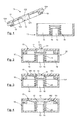
Figure 1 is a schematic sectional view of the different parts, before assembly, forming the pressure regulating valve according to a particular embodiment of the invention; -
Figure 2 is a schematic sectional view of the pressure regulating valve, after assembly of the different parts ofFigure 1 ; -
Figures 3 and 4 are schematic sectional views of the pressure regulating valve ofFigure 2 in operation (Figure 3 showing the valve in open position andFigure 4 showing the valve in closed position). - In all of the figures of the present document, identical elements and steps are designated by the same numerical reference sign.
- The invention provides an improved pressure regulating valve whose assembly is simple to implement and whose conception ensures a proper tightness of the pressure regulating valve. To that end, the valve closing body is overmolded on the valve housing cover before assembly of the latter one on the valve housing.
- A particular embodiment of the pressure regulating valve of the invention is described in relation to
Figures 1 to 4 . In this exemplary embodiment, it is intended for installation in the vent line between the crankcase and the intake manifold of an internal combustion engine of a motor vehicle in order to regulate blow-by gases. - However, it is also possible for the pressure regulating valve of the invention to be used for pressure regulation of other fluids (liquids or gases).
- The pressure regulating valve of the invention may for instance be employed in an air fuel, or oil circuit of an internal combustion engine of a motor vehicle.
-
Figure 1 shows a sectional view of the different elements forming the pressure regulating valve before assembly, namely avalve housing 10 and a valve cover, or cap, 15. Thevalve cover 15 comprises asubstrate cover 11 and amembrane 12, which is overmolded on thesubstrate cover 11. - The pressure regulating valve obtained after assembly of these different elements is represented in
Figure 2 withnumeral reference 20. - The
valve housing 10 is of circular shape and is open at the top. It comprises a bottom surface, or base, and a lateral cylindrical wall extending from the base, the base and wall defining achamber 18. - The
chamber 18 communicates with an air inlet port (not represented) through which gases, which form in the crankcase, enter. Avalve seat 16 in the shape of a hollow cylindrical part extends from the bottom surface of thevalve housing 10 and defines anair outlet port 13 through which gases are aspirated from the crankcase into the intake manifold. - A
compression spring 26 is supported on the bottom surface of thevalve housing 10 and surrounds thevalve seat 16. As will be seen below,spring 26 supports and urges the valve closing portion of the flexible overmolded membrane 12 (also called a diaphragm) against thevalve cover 15, i.e. away from thevalve seat 16. Under some specific operating conditions, the valve closing portion of themembrane 12 closes thevalve seat 16 against the force of thespring 26. - The
circular cover 15 comprises a through hole (or aperture) 14 in its centre. In this example, the throughhole 14 has a shape of an inverted truncated cone. In other words, the diameter of thehole 14 on the outer surface of thecover 15 is larger than the diameter of thehole 14 on its inner surface. - The
cover 15 comprises an annular shoulder 19 (having a general "L" shape) extending from its inner surface for connecting thecover 15 with thevalve body 10. - In order to mold the material forming the
membrane 12 over thecover 15, thecover 15 is positioned in an injection mould and molten material is injected in the mold in order to form themembrane 12. - The mold is designed so that molten material designed to form the
membrane 12, comes into contact with the inner surface of thecover 15 and fills the throughhole 14. The mold is also designed so that the molten material fills thecircular groove 20 formed by theshoulder 19 and surrounds theshoulder 19. Once the injected material has solidified, themembrane 12 is bonded to thecover 15 as illustrated inFigure 1 . - The
cover 15 obtained by such an overmolding step forms a single-piece consisting of thesubstrate cover 11 and theovermolded membrane 12. Thecover 15 can then be mounted on thevalve housing 10 as shown inFigure 2 . - The assembly of the
pressure regulating valve 20 is thus easier to carry out since the approach of the invention requires an assembly of two parts only, i.e. thecover 15 carrying theovermolded membrane 12 and thevalve housing 10. It is thus no longer required to position manually the membrane on the valve housing contrary to the prior art solution. The assembly of the pressure regulating valve of the invention is therefore quicker. - Overmolding the
membrane 12 on thecover 15 further ensures an accurate positioning of themembrane 12 between thecover 15 and thevalve housing 10, as it is no longer necessary to position manually themembrane 12 in a groove of the valve housing as in the prior art approach. The risk that themembrane 12 is damaged during the assembly of thepressure regulating valve 20 is also significantly reduced. - The
overmolded membrane 12 extending on the inner surface and on the periphery of thecover 15, themembrane 12 ensures a proper tightness of thepressure regulating valve 20 when thecover 15 is fitted on thevalve housing 10, by press fitting or by screwing (figure 2 ). - In this exemplary embodiment, the diameter of the
cover 15 is chosen so that thecover 15 rests on the top end of the wall of thevalve housing 10 when thecover 15 is positioned on thevalve housing 10. The outside diameter of theshoulder 19 once it is overmolded is substantially equal to the larger diameter of thechamber 18 so that the part of themembrane 12 surrounding theshoulder 19 is in contact with the inner wall of thevalve housing 10 when thecover 15 is positioned on thevalve housing 10. - In this exemplary embodiment, the
membrane 12 is overmolded on thecover 15 so as to form anannular protuberance 124 intended to be compressively deformed during the assembly of thecover 15 on thevalve housing 10. - These aspects ensure an optimum tightness of the
pressure regulating valve 20 once assembled, and thus minimize the risks of leakage. - In this embodiment, the
substrate cover 11 is manufactured from a thermoplastic. - More generally, the material used for manufacturing the
substrate cover 11 shall bear the temperature at which themembrane 12 is molded over thesubstrate cover 11. The material of thesubstrate cover 11 shall also withstand mechanical stresses during the assembly of thecover 15 on thevalve housing 10. Thus, the material chosen must be rigid but also slightly flexible to allow a press fitting of thecover 15 on thevalve housing 10. - The
membrane 12 is manufactured from an elastomer for instance. The material used for manufacturing the membrane must be adapted to be molded and shaped at high temperatures and to bond with the material of the substrate cover 11 (it must be different from the material used for manufacturing the substrate cover 11). - After assembly of the
valve 20, themembrane 12 is bonded to thesubstrate cover 11, as shown inFigure 2 . As will be described below, in operating conditions of thepressure regulating valve 20, part of theovermolded membrane 12, i.e. the valve closing portion of themembrane 12, cooperates with thevalve seat 16. In other words, the valve closing portion must be flexible so as to move between an open position of thevalve seat 16 and a closed position. - To enable the valve closing portion to be movable between these open and closed position, it is necessary to apply a manual or automatic pressure on the
top surface 21 of themembrane 12, i.e. push (as represented by the arrow A ofFigure 2 ) theconical part 122 of themembrane 12 located inside thehole 14 out of thishole 14. - The upper
conical part 122, the lowercylindrical part 121 and the surrounding part (or skirt) 123 of themembrane 12 are thus separated from thecover 11 over which they were previously molded. However, thepart 124 of themembrane 12 surrounding theshoulder 19 remains bonded to thesubstrate cover 11 and forms a collar. To that end, materials forming themembrane 12 and thecover 11 are chosen so that themembrane 12 and thecover 11 have a bonding surface that is at least partially detachable (there is thus no chemical adhesive applied in the detachable areas prior to the overmolding step). - Once this step is carried out, the
valve closing portion membrane 12 is then movable against or away from thevalve seat 16. - It is to be noted that the step illustrated in
Figure 2 is carried out without deteriorating the tightness of thepressure regulating valve 20. - Also, after this step, the
membrane 12 is irreversibly displaced in its active position (Figure 3 ) with no possible return in the inactive position (Figure 2 ). - Indeed, the
conical part 122 of the closingportion hole 14, the closing portion of themembrane 12 cannot return from its active position (Figure 3 ) to its inactive position (Figure 2 ). - Once the
pressure regulating valve 20 is activated, thevalve closing portion overmolded membrane 12 is moveable between an open position (Figure 3 ) in which thevalve opening 13 is opened, allowing blow-by gas to flow from thechamber 18 into the outlet port 13 (as shown by the arrow), and a closed position (Figure 4 ) in which theoutlet port 13 is closed by the valve closing portion which is urged against thevalve seat 16. In the closed position, blow-by gas cannot flow through theoutlet port 13. - The
chamber 18 is divided by thevalve closing portion flexible membrane 12 into afirst chamber 181 that has thevalve seat 16, and asecond chamber 182 communicating with the ambient atmospheric pressure via thehole 14. - With the
valve closing portion Figure 3 , gases which form in the crankcase, and enter through the inlet port of thechamber 18, are aspirated through theoutlet port 13 toward the intake manifold. As the pressure in the crankcase falls toward a predetermined level, which is lower than the atmospheric pressure, thevalve closing portion valve seat 16 until the passage is shut off. - In the closed position of
Figure 4 , no blow-by gases flow from the crankcase into the intake manifold. As the pressure in the crankcase increases or the pressure in the intake manifold decreases, thevalve closing portion valve seat 16. - The
pressure regulating valve 20 may be manufactured according to the following method which comprises the steps of: - providing the
substrate cover 11 intended to be mounted on thevalve housing 10, thesubstrate cover 11 having a throughhole 14 with an inverted truncated cone shape, - molding a
membrane 12 over part of thesubstrate cover 11 so as to form a single-piece element or cover 15, theovermolded membrane 12 being intended to ensure the tightness of thepressure regulating valve 20, - mounting, by press fitting, the
cover 15 on thevalve body 10, so as to obtain thepressure regulating valve 20, - applying a pressure A on the
part 122 of theovermolded membrane 12 located in the throughhole 14 in order to shift irreversibly themembrane 12 from its inactive position to its active position, and make thepressure regulating valve 20 operational. - According to an advantageous aspect of the invention, previously to the overmolding step, a chemical adhesive can be applied to the vicinity of the
shoulders 19 of thecover 11, so that thepart 124 of theovermolded membrane 12 remains bonded with thesubstrate cover 15 in this particular area when themembrane 12 is placed into its active (operating) position. - The closing body may not be a membrane or diaphragm but a piston when the valve of the invention is intended to be used as a piston actuator for instance.
- Although the present disclosure has been described with reference to one or more examples, workers skilled in the art will recognize that changes may be made in form and detail without departing from the scope of the disclosure and/or the appended claims.
Claims (15)
- A pressure regulating valve (20) comprising:- a valve housing (10) having a valve cap (15),- a valve closing body (12) disposed within said valve housing (10) and cooperating with a valve seat (16), and- a spring (26) which urges said valve closing body (12) away from said valve seat (16),
characterized in that said valve closing body (12) is molded over said valve cap (15). - A pressure regulating valve (20) according to claim 1, characterized in that said valve closing body (12) comprises a movable valve closing portion (121, 122, 123) cooperating with said valve seat (16) and a fixed collar (124) fastened to the periphery of the valve cap (15).
- A pressure regulating valve (20) according to claim 2, characterized in that said movable valve closing portion (121, 122, 123) divides said valve housing (10) into a first chamber (181) in which the valve seat (16) is disposed and a second chamber (182) communicating with the atmosphere.
- A pressure regulating valve (20) according to claim 3, characterized in that said valve cap (15) comprises a through hole (14) connecting said second chamber (182) to the atmosphere.
- A pressure regulating valve (20) according to claim 4, characterized in that through hole (14) has a conical shape.
- A pressure regulating valve (20) according to claim 5, characterized in that said movable valve closing portion (121, 122, 123) comprises a conical portion (122).
- A pressure regulating valve (20) according to claim 6, characterized in that said conical portion (122) is molded inside said through hole (14) and separated from said through hole (14).
- A pressure regulating valve (20) according to any one of claims 2 to 7, characterized in that said collar (124) rests against the lateral wall of said valve housing (10).
- A pressure regulating valve (20) according to any one of claims 1 to 8, characterized in that said spring (26) rests against the bottom surface of said valve housing (10) and urges said valve closing body (12) toward said valve cap (15).
- A pressure regulating valve (20) according to any one of claims 1 to 9, characterized in that the valve closing body (12) is a diaphragm
- A pressure regulating valve (20) according to any one of claims 1 to 9, characterized in that the valve closing body (12) is a piston.
- A pressure regulating valve (20) according to any one of claims 1 to 11, characterized in that said pressure regulating valve (20) is disposed in a vent duct communicating between a crankcase of an internal combustion engine and an intake manifold of said engine.
- A pressure regulating valve (20) according to any one of claims 1 to 12, characterized in that said overmolded valve closing body (12) is made of an elastically deformable material and the valve cap (15) is made of a rigid material.
- A pressure regulating valve (20) according to claim 13, characterized in that said overmolded valve closing body (12) is manufactured from an elastomer.
- A pressure regulating valve (20) according to claim 13 or 14, characterized in that said valve cap (15) is manufactured from a plastic.
Priority Applications (1)
| Application Number | Priority Date | Filing Date | Title |
|---|---|---|---|
| EP13290189.3A EP2837780A1 (en) | 2013-08-13 | 2013-08-13 | Pressure regulating valve |
Applications Claiming Priority (1)
| Application Number | Priority Date | Filing Date | Title |
|---|---|---|---|
| EP13290189.3A EP2837780A1 (en) | 2013-08-13 | 2013-08-13 | Pressure regulating valve |
Publications (1)
| Publication Number | Publication Date |
|---|---|
| EP2837780A1 true EP2837780A1 (en) | 2015-02-18 |
Family
ID=49303912
Family Applications (1)
| Application Number | Title | Priority Date | Filing Date |
|---|---|---|---|
| EP13290189.3A Withdrawn EP2837780A1 (en) | 2013-08-13 | 2013-08-13 | Pressure regulating valve |
Country Status (1)
| Country | Link |
|---|---|
| EP (1) | EP2837780A1 (en) |
Cited By (2)
| Publication number | Priority date | Publication date | Assignee | Title |
|---|---|---|---|---|
| CN105402456A (en) * | 2015-08-21 | 2016-03-16 | 中国人民解放军国防科学技术大学 | Valve element of gas pressure reducer |
| CN105422868A (en) * | 2015-08-21 | 2016-03-23 | 中国人民解放军国防科学技术大学 | Pneumatic-control type gas pressure reducer |
Citations (3)
| Publication number | Priority date | Publication date | Assignee | Title |
|---|---|---|---|---|
| US4267855A (en) * | 1980-01-17 | 1981-05-19 | Eaton Corporation | Pneumatic vacuum regulator |
| WO2005033818A1 (en) * | 2003-10-03 | 2005-04-14 | Swagelok Company | Pressure regulator with over-molded poppet |
| DE102008030203A1 (en) * | 2008-06-25 | 2009-12-31 | Mahle International Gmbh | Pressure control valve |
-
2013
- 2013-08-13 EP EP13290189.3A patent/EP2837780A1/en not_active Withdrawn
Patent Citations (3)
| Publication number | Priority date | Publication date | Assignee | Title |
|---|---|---|---|---|
| US4267855A (en) * | 1980-01-17 | 1981-05-19 | Eaton Corporation | Pneumatic vacuum regulator |
| WO2005033818A1 (en) * | 2003-10-03 | 2005-04-14 | Swagelok Company | Pressure regulator with over-molded poppet |
| DE102008030203A1 (en) * | 2008-06-25 | 2009-12-31 | Mahle International Gmbh | Pressure control valve |
Cited By (2)
| Publication number | Priority date | Publication date | Assignee | Title |
|---|---|---|---|---|
| CN105402456A (en) * | 2015-08-21 | 2016-03-16 | 中国人民解放军国防科学技术大学 | Valve element of gas pressure reducer |
| CN105422868A (en) * | 2015-08-21 | 2016-03-23 | 中国人民解放军国防科学技术大学 | Pneumatic-control type gas pressure reducer |
Similar Documents
| Publication | Publication Date | Title |
|---|---|---|
| US8613854B2 (en) | Filter element for liquid filters and liquid filter | |
| US6085771A (en) | Two-stage fuel tank vapor recovery vent valve and method of making same | |
| US8733402B2 (en) | Pressure control valve | |
| US9086161B2 (en) | Valve apparatus with positive and negative pressure relief valves | |
| JP2006266265A (en) | Low-contour overfill restricting device having reverse distribution performance | |
| CN101809522A (en) | Thermostatic valve with sleeve, thermal engine associated with a cooling circuit including such valve, and method for making the sleeve for such valve | |
| US6484741B2 (en) | Fuel tank vapor vent valve assembly and method of making same | |
| US11169549B2 (en) | Unit for the regulation or control of a fluid pressure | |
| AU2002234818A1 (en) | Fuel tank vent valve and method of mounting | |
| US20040041119A1 (en) | Pressure-regulating valve | |
| CN105888887B (en) | Air valve with improved sealing properties | |
| CN110388288B (en) | Functional components for influencing the ventilation of the fuel tank and their arrangement on the suction duct | |
| CN101031718B (en) | Pressure regulator for a fuel supply unit and method for production of a pressure regulator | |
| CN110100128A (en) | Valve | |
| US20070079877A1 (en) | Structure of crankcase pressure control valve with bent nipple | |
| JP2018145954A (en) | Structure for fixing additional element to hole formed at resin duct | |
| KR100876468B1 (en) | PCV valve | |
| CN111433502A (en) | Valve with a valve body | |
| CN113357381A (en) | Flow control valve | |
| WO2017042988A1 (en) | Fuel tank valve | |
| US8893681B2 (en) | Pressure support for engine valve stem seals | |
| JPH05272651A (en) | Valve | |
| KR100876469B1 (en) | PCV valve | |
| WO2019077450A1 (en) | Automatic air vent and safety valve integrated in the cartridge | |
| KR100876467B1 (en) | PCV valve |
Legal Events
| Date | Code | Title | Description |
|---|---|---|---|
| 17P | Request for examination filed |
Effective date: 20130813 |
|
| AK | Designated contracting states |
Kind code of ref document: A1 Designated state(s): AL AT BE BG CH CY CZ DE DK EE ES FI FR GB GR HR HU IE IS IT LI LT LU LV MC MK MT NL NO PL PT RO RS SE SI SK SM TR |
|
| AX | Request for extension of the european patent |
Extension state: BA ME |
|
| PUAI | Public reference made under article 153(3) epc to a published international application that has entered the european phase |
Free format text: ORIGINAL CODE: 0009012 |
|
| STAA | Information on the status of an ep patent application or granted ep patent |
Free format text: STATUS: THE APPLICATION IS DEEMED TO BE WITHDRAWN |
|
| 18D | Application deemed to be withdrawn |
Effective date: 20150819 |