EP2837725A1 - Laundry treatment device having a control panel assembly - Google Patents
Laundry treatment device having a control panel assembly Download PDFInfo
- Publication number
- EP2837725A1 EP2837725A1 EP13180217.5A EP13180217A EP2837725A1 EP 2837725 A1 EP2837725 A1 EP 2837725A1 EP 13180217 A EP13180217 A EP 13180217A EP 2837725 A1 EP2837725 A1 EP 2837725A1
- Authority
- EP
- European Patent Office
- Prior art keywords
- light
- treatment device
- laundry treatment
- circuit board
- printed circuit
- Prior art date
- Legal status (The legal status is an assumption and is not a legal conclusion. Google has not performed a legal analysis and makes no representation as to the accuracy of the status listed.)
- Withdrawn
Links
- 239000000463 material Substances 0.000 claims description 18
- 229920003023 plastic Polymers 0.000 claims description 14
- 239000004033 plastic Substances 0.000 claims description 11
- QHZSDTDMQZPUKC-UHFFFAOYSA-N 3,5-dichlorobiphenyl Chemical compound ClC1=CC(Cl)=CC(C=2C=CC=CC=2)=C1 QHZSDTDMQZPUKC-UHFFFAOYSA-N 0.000 description 36
- 238000005406 washing Methods 0.000 description 8
- 239000003599 detergent Substances 0.000 description 7
- 230000008878 coupling Effects 0.000 description 6
- 238000010168 coupling process Methods 0.000 description 6
- 238000005859 coupling reaction Methods 0.000 description 6
- 238000005286 illumination Methods 0.000 description 5
- 239000002184 metal Substances 0.000 description 4
- 229910052751 metal Inorganic materials 0.000 description 4
- 230000009471 action Effects 0.000 description 3
- 238000000034 method Methods 0.000 description 3
- 238000005476 soldering Methods 0.000 description 3
- 230000004913 activation Effects 0.000 description 2
- 230000009849 deactivation Effects 0.000 description 2
- 238000005304 joining Methods 0.000 description 2
- 238000012423 maintenance Methods 0.000 description 2
- 238000002156 mixing Methods 0.000 description 2
- 238000012986 modification Methods 0.000 description 2
- 230000004048 modification Effects 0.000 description 2
- 230000003287 optical effect Effects 0.000 description 2
- 230000037361 pathway Effects 0.000 description 2
- 230000008439 repair process Effects 0.000 description 2
- 229910001220 stainless steel Inorganic materials 0.000 description 2
- 239000010935 stainless steel Substances 0.000 description 2
- 238000003466 welding Methods 0.000 description 2
- RYGMFSIKBFXOCR-UHFFFAOYSA-N Copper Chemical compound [Cu] RYGMFSIKBFXOCR-UHFFFAOYSA-N 0.000 description 1
- 238000013459 approach Methods 0.000 description 1
- 238000003491 array Methods 0.000 description 1
- 230000008901 benefit Effects 0.000 description 1
- 230000004397 blinking Effects 0.000 description 1
- 230000008859 change Effects 0.000 description 1
- 239000011248 coating agent Substances 0.000 description 1
- 238000000576 coating method Methods 0.000 description 1
- 239000003086 colorant Substances 0.000 description 1
- 238000012790 confirmation Methods 0.000 description 1
- 238000010276 construction Methods 0.000 description 1
- 229910052802 copper Inorganic materials 0.000 description 1
- 239000010949 copper Substances 0.000 description 1
- 238000005260 corrosion Methods 0.000 description 1
- 230000007797 corrosion Effects 0.000 description 1
- 238000013461 design Methods 0.000 description 1
- 238000003780 insertion Methods 0.000 description 1
- 230000037431 insertion Effects 0.000 description 1
- CNQCVBJFEGMYDW-UHFFFAOYSA-N lawrencium atom Chemical compound [Lr] CNQCVBJFEGMYDW-UHFFFAOYSA-N 0.000 description 1
- 238000004519 manufacturing process Methods 0.000 description 1
- 239000007769 metal material Substances 0.000 description 1
- 239000002991 molded plastic Substances 0.000 description 1
- 238000010137 moulding (plastic) Methods 0.000 description 1
- 150000003071 polychlorinated biphenyls Chemical class 0.000 description 1
- 238000003825 pressing Methods 0.000 description 1
- 230000008569 process Effects 0.000 description 1
- 230000000750 progressive effect Effects 0.000 description 1
- 238000004080 punching Methods 0.000 description 1
- 230000000284 resting effect Effects 0.000 description 1
- 238000000926 separation method Methods 0.000 description 1
- 238000009987 spinning Methods 0.000 description 1
- 239000000758 substrate Substances 0.000 description 1
- 239000012780 transparent material Substances 0.000 description 1
- 230000000007 visual effect Effects 0.000 description 1
Images




Classifications
-
- D—TEXTILES; PAPER
- D06—TREATMENT OF TEXTILES OR THE LIKE; LAUNDERING; FLEXIBLE MATERIALS NOT OTHERWISE PROVIDED FOR
- D06F—LAUNDERING, DRYING, IRONING, PRESSING OR FOLDING TEXTILE ARTICLES
- D06F34/00—Details of control systems for washing machines, washer-dryers or laundry dryers
- D06F34/28—Arrangements for program selection, e.g. control panels therefor; Arrangements for indicating program parameters, e.g. the selected program or its progress
- D06F34/34—Arrangements for program selection, e.g. control panels therefor; Arrangements for indicating program parameters, e.g. the selected program or its progress characterised by mounting or attachment features, e.g. detachable control panels or detachable display panels
-
- D—TEXTILES; PAPER
- D06—TREATMENT OF TEXTILES OR THE LIKE; LAUNDERING; FLEXIBLE MATERIALS NOT OTHERWISE PROVIDED FOR
- D06F—LAUNDERING, DRYING, IRONING, PRESSING OR FOLDING TEXTILE ARTICLES
- D06F2101/00—User input for the control of domestic laundry washing machines, washer-dryers or laundry dryers
-
- D—TEXTILES; PAPER
- D06—TREATMENT OF TEXTILES OR THE LIKE; LAUNDERING; FLEXIBLE MATERIALS NOT OTHERWISE PROVIDED FOR
- D06F—LAUNDERING, DRYING, IRONING, PRESSING OR FOLDING TEXTILE ARTICLES
- D06F2105/00—Systems or parameters controlled or affected by the control systems of washing machines, washer-dryers or laundry dryers
- D06F2105/58—Indications or alarms to the control system or to the user
Definitions
- the present invention generally relates to a laundry treatment device, such as front/top loading washing machines, washers/dryers, dryers, both for domestic and professional use. More particularly, the present invention relates to a laundry treatment device including a control-panel assembly.
- Each household and professional laundry treatment device (hereinafter, appliance, for the sake of conciseness) -such as washing machine, washer/dryer, dryer- typically comprises a substantially parallepiped-shaped cabinet enclosing an inner compartment for housing items to be treated (e.g. , laundry to be washed and/or dried), an access door for accessing the inner compartment thereby allowing loading/unloading operations of the items by a user, and a manually-operable dashboard (typically including control members, also called input devices, e.g. , rotatable knobs, display devices, buttons, switches and the like) for allowing the user to manually control operation of the appliance and ascertain an operational state thereof.
- appliance typically comprises a substantially parallepiped-shaped cabinet enclosing an inner compartment for housing items to be treated (e.g. , laundry to be washed and/or dried), an access door for accessing the inner compartment thereby allowing loading/unloading operations of the items by a user, and a manually-operable dashboard (typical
- the dashboard represents an exposed part of a control-panel assembly, which typically is connected to an inner printed circuit board (or PCB) that is electrically connected to electronic components and the control members associated therewith for implementing corresponding control functionalities, e.g. powering, driving, activation, deactivation of operative loads including electric, electronic, electro-mechanical and/or electro-hydraulic parts of the appliance (such as motor, solenoid valve, further PCBs and the like).
- PCB printed circuit board
- the PCB is typically coupled with the operative loads to be controlled, and to an electrical power supply, by means of one or more electrical cables or wires provided with electrical connectors (in the following, connectors, configured in such a way to be properly mounted on the PCB for contacting respective electrical terminal - or terminals - of the electronic components on the PCB), so as to mechanically and electrically joining the PCB to one or more of the operative loads which the PCB has to be connected to and/or to the electrical power supply.
- electrical connectors in the following, connectors, configured in such a way to be properly mounted on the PCB for contacting respective electrical terminal - or terminals - of the electronic components on the PCB
- connectors are mounted on an edge of the PCB by means of mechanical pressure.
- the connectors could be straddle-mounted the edge of the PCB and they are fixed therein by the pressure necessary to slot the connector in the PCB.
- soldering resists vibrations, it is a permanent connection, in other words it is not possible to detach and re-couple again the connectors in a simple manner. Indeed, the mounting and dismounting of the connectors could be needed in case of repair and maintenance of the device.
- the invention relates to a laundry treatment device having a casing and a control-panel assembly for controlling operation of the laundry treatment device, said assembly comprises:
- the laundry treatment device is a washing device or a dryer or a washer-dryer.
- the laundry treatment device includes a casing delimiting the appliance.
- the casing includes a front wall and a top wall.
- the control panel assembly is manually operated by a user in order to select one or more of the available programs for the laundry treatment or to input any data relative to the functioning of the appliance.
- the control panel assembly can also display warning messages or instruction for maintenance coming directly from the household appliance.
- the control panel assembly can be coupled to any portion of the casing of the laundry treatment device, for example typically to the front wall or the top wall, depending whether the laundry treatment device is of the front loading or top loading type.
- the front/top wall and the dashboard are made of different materials.
- the front/top wall is made of metal and the dashboard of plastic material.
- the outer dashboard defines an outer surface which, in an assembled configuration, preferably substantially forms a geometrical continuation of a front surface of the front wall or top wall (depending on where the panel assembly is coupled to), e.g., it does not protrudes or sticks out in a significant manner, but it is substantially flush to the same, so that the front wall globally has a pleasant aesthetical appearance.
- the outer dashboard includes light indicators in order to control operation of the laundry treatment device or issue possible warning messages directed to the user or to the repair technician.
- Light indicators can also be used to show the program(s) which have been selected by the user.
- Light indicators include generally openings formed in the dashboard, for example covered by a transparent material, which show light coming from light sources present in the printed circuit board located at the light indicators.
- the material of the dashboard at the light indicators could be substantially transparent to light.
- the light sources include LEDs, which could be advantageously designed to emit colored light, preferably also in different colors, and/or with different intensities.
- each LED is apt to illuminate its corresponding light indicator present in the dashboard with light of a different color/intensity with respect to light reaching another light indicator so that different information could be displayed and become evident to the user.
- the indicators relative of warning messages and/or malfunctioning of the device could be illuminated in red, while the indicators relative to the status of the device (e.g., washing, rinsing, spinning, etc.) could be colored in green.
- all LEDs present in the printed circuit board emit light having substantially the same color and/or intensity.
- light guides are used, one for each light source, which transport the light emitted by the light sources from the printed circuit board to the dashboard.
- Light guides could for example include light transparent rods having one end abutting on the light source and the other end abutting on the corresponding light indicator.
- a light separator In order not to mix the light coming from different light sources, i.e., in order to visualize in each light indicator on the dashboard substantially only the light of a corresponding light source programmed to emit light under certain conditions, so as not to confuse the user (for example, in case the light of one light source illuminates two indicators, the user cannot understand which information is meant to be given), a light separator is commonly employed. Light separator optically separates light coming from each light source, so that each light indicator in the dashboard is shone substantially only by the light of its corresponding light source.
- Light separator separates light from one light source to the other(s) for a given optical path, e.g. for a given distance, this distance being preferably the distance separating the printed circuit board to the outer dashboard. Then, at the outside, the light emitted from the light sources can merge.
- the printed circuit board is connected through one or more electrical connectors to electric loads of the device, such as the motor of the same and/or to a power supply.
- the electrical connector is fixed to the printed circuit board and it is in contact with terminals formed on the same.
- the terminals are formed on a contact region of the printed circuit board.
- a supporting member is provided, to support the connector on the contact region so that it stays electrically connected to the same.
- the light separator is used to carry such supporting member, e.g. the body of the light separator also includes the supporting member.
- said contact portion is formed substantially in proximity of an edge of said printed circuit board and said supporting member is formed in a corresponding edge of said light separator.
- the electrical connector is preferably reachable by the user or by a technician, and more preferably in an easy manner when the control panel assembly is detached from the casing of the laundry treatment device.
- said printed circuit board includes an active surface and a rear surface opposite to the active surface, said terminal portion being formed in both said active and said rear surface.
- a wide region with terminals assures a better electrical contact between the printed circuit board and the connector.
- the active surface of the printed circuit board is defined as the surface in which conductive pathways, tracks or signal traces are formed. Generally all these conductive pathways and tracks are etched from copper sheets laminated onto a non-conductive substrate. On this surface also the light sources are present.
- said printed circuit board includes an active surface and a rear surface opposite to the active surface, said light separator faces said active surface, and said supporting member, after the mounting of the control-panel assembly, protrudes beyond said active surface toward said rear surface of the printed circuit board and forms a seat for guiding the electrical connector to the contact region.
- the contact region is located on both opposite surfaces of the printed circuit board, in order to assure a proper support of the connector in such a region, it is preferred that the supporting element is also extending beyond both sides of the printed circuit board.
- said supporting member includes a C- or U-shaped member having a shape substantially matching at least part of the shape of said electrical connector for guiding the electrical connector in said contact region.
- the supporting member can thus firmly mechanically hold the connector between the arms of the C- or U-shaped member.
- said supporting member includes an elastic clip element to hold said electrical connector within said supporting member.
- the supporting element also elastically blocks the latter inside the C- or U-shaped member to improve the stability of the connection between the connector and the contact region.
- said printed circuit board includes an active surface and a rear surface opposite to the active surface
- said electrical connector is configured so as to be mounted straddle said active surface and rear surface of said printed circuit board
- said supporting member is extending from said active surface to said rear surface bridging an edge of said printed circuit board for guiding the straddle-mounted electrical connector both at the active surface and at the rear surface.
- said C- or U-shaped member is substantially perpendicular to said active surface and/or rear surface and it is abutting against the edge of said printed circuit board.
- the straddle mounted connector which is straddle the rear and active surface, is kept in place by the C- or U-shaped member which is located on the edge of the printed circuit board holding the connector on the two surfaces.
- the panel control assembly includes a box-like member interposed between said printed circuit board and said outer dashboard, said box-like member having a front wall and side walls, said first and second light guides protruding from said front wall, said box like member including a recessed area in one of its side walls for exposing said electric connector and allowing connection thereof with one or more loads of said laundry treatment device.
- the box-like member has the function of protection of the printed circuit board.
- the light guides are integral to the box-like member.
- the box-like member can be molded as a single piece of plastic, more preferably, it is made of a transparent plastic material, so that it can guide light.
- said light separator includes at least a first and a second through-holes, a first and second aperture of said first and second through-holes being superimposed to, when said control-panel assembly is mounted, said first and second light source, respectively, said first and second through-holes further including a first and second inner surface, respectively, guiding the first and second light emitted by said first and second light sources in a separate manner.
- said first and second light guides are inserted in said first and second through-holes, respectively.
- Said light separator in a depicted embodiment is a monolithic element.
- the light separator can be molded as a single piece together with the guiding element. It is indeed preferred that the number of parts of the panel assembly are as little as possible so that the assembly is quick and easy reducing mounting costs and time.
- the plastic material in which the light separator is formed is preferably flexible enough to form a supporting member substantially elastic and thus supporting the connectors in the right position, e.g. so that the connectors are electrically connected to the contact region(s), also when the laundry device vibrates.
- said light separator is coupled to said printed circuit board by means of at least an appendix provided in one of said light separator and printed circuit board housed in a corresponding seat formed in the other of said light separator and printed circuit board.
- the light separator is directly coupled to the printed circuit board in an easy manner so that undesired relative movements between the light separator and the printed circuit board, and thus of the connectors, are minimized.
- the guiding member and the connector are substantially a single rigid block.
- said light separator is made of a plastic material not transparent to said first and second light.
- the light separator is a piece of molded plastic which is not transparent to light (or at least to a very minor extent) so that it can be produced in a rather economical manner and at the same time can be effective in separating the light from the different light sources.
- said casing includes a front wall defining a continuous front surface having a panel aperture, said control-panel assembly being coupled to said panel aperture.
- the front wall of the casing has a front surface which is a continuous surface having at least an aperture which is called panel aperture.
- This front surface represents the external front surface of the appliance and it is construed as a single continuous surface holed by the panel aperture.
- Single piece means that there are no junctions or seams in the front surface connecting different pieces together.
- These front walls are in jargon also called “full front”.
- the front wall can also include additional element(s) separated from the portion of the front wall defining the continuous front surface.
- the front wall could include a first portion having a panel aperture to host the control-panel assembly which is positioned in the top-most part of the front wall, and a second portion, separated from the first, which covers the lowermost part of the front wall.
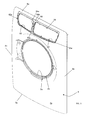
- Figure 1 schematically shows a perspective view of a laundry treatment device 100 according to the present invention.
- the teaching of the present invention may be applied to substantially any appliance for laundry treatment, e.g., to washer/dryers, washing machines (as exemplary illustrated in the figures and to which reference will be made in the following by way of a non-limiting example only), dryers (e.g. tumble dryers), etc.
- appliance for laundry treatment e.g., to washer/dryers, washing machines (as exemplary illustrated in the figures and to which reference will be made in the following by way of a non-limiting example only), dryers (e.g. tumble dryers), etc.
- the device 100 comprises a, preferably substantially parallelepiped-shaped, casing 2, which encloses an inner compartment comprising a laundry treatment chamber, for example a rotating drum 12' for housing the laundry to be treated and a tub encasing the drum (tub is not visible in the appended drawings).
- a laundry treatment chamber for example a rotating drum 12' for housing the laundry to be treated and a tub encasing the drum (tub is not visible in the appended drawings).
- the device includes an access door 3 provided on a front wall 4 for accessing the laundry treatment chamber 12' thereby allowing loading/unloading of the laundry by a user.
- the casing 2 preferably also includes a bottom wall or basement 7, a top wall 6, a back wall (not visible), and two opposite lateral walls (only one of the two visible in figures 1 and 2 ) 9.
- lateral walls, front walls, top wall and basement are separated pieces which are then assembled together via suitable fastening means.
- some of these walls can be a single piece, for example lateral walls and back wall can be a single C- or U-shaped piece. Walls are preferably made of metal, however also plastic is possible.
- some of the walls can be made of a material, and some other(s) can be made of a different material.
- a horizontal plane is defined (plane (XY) in Figure 1 ), which is generally the plane on which the bottom wall or basement 7 lies and generally it is also parallel to the top wall 6 of the casing in a mounted configuration.
- the appliance also extends along a vertical direction denoted with Z (see Figure 1 ).
- the front wall 4 includes an external continuous surface 4a having a plurality of apertures, as better detailed below.
- the front external surface is the external front surface of the appliance.
- Front wall 4 is preferably made of a metallic material, for example in stainless steel.
- the front surface 4a is preferably continuous and even more preferably seamless, at least in the visible portion(s) of the same.
- Continuous surface means that the surface is formed as a single member.
- Sealess means that, in addition to be continuous, there are no seams which indicate that for example welding has been used to join together different parts.
- portions of the front wall 4 can be present. The absence of seams improves the overall appearance of the laundry treatment device 100.
- the front wall 4 preferably includes four rounded corners 4b, 4c, 4d, 4e along its outer edge.
- "Rounded corner” means a corner which does not include sharp and abrupt changes in directions of the surfaces forming the same; on the contrary in a rounded corner the surfaces merges smoothly and with continuity.
- the round corners give a more aesthetically pleasant look to the device 100, and they also make the use of the device safer for the user, which could be injured by sharp corners
- the front wall 4 can be obtained by a single sheet of metal.
- it can be obtained by a sheet of stainless steel.
- the front wall can be coated by suitable coating to prevent corrosion.
- the front wall can be colored of any color and gloss.
- the front wall 4 defines a top portion 4a', a middle portion 4a"' and a bottom portion 4a", the terms “top”, “middle” and “bottom” used with reference to the standard standing configuration of the household appliance when in use.
- top portion 4a' and the middle portion 4a"' of the front wall 4 are a single (or one-piece) element, i.e., having a continuous and/or seamless front surface 4a, while the bottom portion 4a" can be permanently fixed to it, for example welded to it, or it can even be added as an additional element which can be disassembled from the rest of the front wall.
- the front wall 4 includes an outer edge which can be divided in a top edge 50a, which is the portion of the outer edge comprised between corners 4b and 4c, a bottom edge 50b, which is the portion of the edge located between corners 4d and 4e, and two lateral opposite edges, 50c and 50d which are the portions of outer edge present between corners 4b and 4e, and 4c and 4d, respectively.
- Front surface 4a includes a laundry opening 3a for the access into the laundry treatment device 100, in particular to the laundry treatment chamber 12' so that laundry can be loaded or unloaded to/from the laundry treatment device 100.
- the opening 3a is openable and closable by the door 3, which is advantageously hinged to front wall 4.
- the door 3 is coupled to a recessed portion 3b of the front wall 4: in this embodiment, the front wall 4 includes the recessed portion (see figures 3 and 4 ) in the center of which the door opening 3a is formed.
- the dimensions of the opening 3a are such to be suitable to accommodate the door 3.
- the door 3 is then rotatably coupled to the door opening 3a and, when mounted and in a closed position, it preferably does not project substantially beyond the front surface 4a due to the recess presence. In other words, an outer surface of door 3 matches the front surface 4a of front wall 4.
- the door 3 and the recessed portion 3b are located in the middle portion 4a"' of the front wall.
- the front wall 4 is not flat, i.e., it does not lie completely on a single plane. On the contrary, it includes a concavity pointing, in the assembled configuration, towards the inside of the casing 2, being convex on the outside.
- the front wall 4 - in a section along a plane parallel to plane YZ- has substantially a smoothed trapezoidal shape, the top 4a', the bottom 4a" and the middle portion 4a"' substantially lying on three different planes which form an angle one with respect to the other(s) and also with the vertical direction Z defined by the casing 2, forming in this way the inward concavity.
- the three planes are preferably connected smoothly and without sharp corners.
- the front wall 4 can include a substantially constant curvature, the concavity still oriented towards the inside of the casing.
- the front wall could be a portion of a cylindrical mantel.
- a first and a second side walls 8a, 9a of the front wall 4 extend from its side edges 50c and 50d and are delimited between corners 4b-4e and 4c-4d, respectively.
- the side walls 8a, 9a are substantially a geometrical continuation of the lateral walls of casing 2.
- side walls 8a, 9a and front wall 4 are formed continuously as one body, i.e., they are not an assembly of different pieces but they are integral one to the others, and more preferably there are no seams of welding separating the front from the side walls.
- Side walls and front wall are thus formed as a single piece and even more preferably the front surface 4a of the front wall 4 is smoothly connected to the front surfaces of the side walls 8a and 9a, e.g., no sharp curvature changes are present.
- an upper wall 6a and a bottom wall 7a extend from the top and bottom edge, 50a and 50b, respectively, of the front wall 4.
- upper wall 6a and bottom wall 7a are continuous with the front wall.
- corners 4b, 4c, 4d, 4e formed where side walls and upper/bottom walls merge into the front wall are seamless, because they are not formed by joining different elements, but they are formed during a single process of forming of the front wall, for example by pressing a single metallic sheet.
- the two side walls 8a, 9a extend from the side edges 50c and 50d of the front wall 4 substantially perpendicularly to the front wall 4 towards lateral walls 9, so as to be aligned to the latter.
- upper and bottom walls 6a, 7a extend from the top edge 50a and bottom edge 50b substantially perpendicularly to the front wall 4, respectively towards the top and bottom walls 6,7 of the casing, preferably so as to be aligned with the latter.
- At least one of bottom wall 7a and side walls 8a, 9a, more preferably all of them, includes a flange to secure the front wall 4 to the rest of the casing 2.
- front wall 4 includes a second aperture 15, called panel aperture.
- the front wall 4 includes also a third aperture, called drawer aperture 60.
- the panel aperture 15 and/or the drawer aperture 60 is (are) located at the top portion 4a' of the front wall.
- the panel aperture 15 and the drawer aperture 60 are each substantially a through hole within the front wall, in other words the panel aperture and/or the drawer aperture is(are) completely surrounded in all directions by the front wall 4.
- the panel aperture 15 and/or the drawer aperture 60 includes each an outer edge, 15a and 60a, respectively, which defines a closed curve, such as a loop.
- panel aperture 15 and drawer aperture 60 are located one adjacent to the other substantially at the same height along the Z direction on the front wall 4.
- a bridging crosspiece 66 advantageously separates the panel aperture 15 from the drawer aperture 60 (and vice-versa).
- the crosspiece 66 has an elongated shape and has a longitudinal extension substantially parallel to the vertical axis Z.
- Crosspiece 66 includes a portion of the edge 60a of the drawer aperture 60 and a portion of the edge 15a of the panel aperture 15a, corresponding to its longitudinal opposite edges.
- crosspiece 66 includes a front surface 66a which is oriented towards the outside of the casing 2.
- the front surface 66a of the crosspiece 66 and the front surface 4a of the front wall 4 are a continuous uniform surface, and even more preferably this continuous uniform surface is also seamless.
- the crosspiece 66 is substantially an integral part of the front wall 4: in the front wall 4 there are two apertures, the drawer and panel aperture, and the crosspiece is the "remaining" portion of front wall 4 (for example during a punching procedure of a metal sheet for obtaining the apertures) between the two.
- the crosspiece 66 is attached, for example by means of its opposite longitudinal ends 66b, 66c, to the front wall separating the two apertures 60, 15.
- the crosspiece is not an integral piece to the front wall, but a separated element which is then fixed to the front wall 4.
- drawer aperture and panel aperture might be the same aperture, e.g., a single "bigger” aperture can be obtained on the front wall, having the function of the panel and drawer apertures.
- the front wall may comprise a service aperture 99, (shown only in figure 1 ) preferably covered by a service aperture cover 99a, so that a filter (not visible) of the laundry treatment device 100 might be easily accessible.
- the service aperture 99 is provided at the bottom portion 4a" of the front wall 4.
- Laundry treatment device 100 further includes a panel control assembly 1.
- the control panel assembly 1 includes an outer dashboard 11, which in the depicted embodiment spans for most of the width of the front surface 4a of the appliance.
- the dashboard 11 is substantially a basin-shaped rigid shell.
- dashboard 11 is structured for being coupled to the outer front wall 4 of the appliance.
- the dashboard 11 is made of plastic material.
- the dashboard 11 is preferably configured for allowing the user to manually control operation of the appliance and ascertain an operational state thereof.
- the dashboard includes a portion 11ext, external to the casing 2 when laundry treatment device 100 is in the assembled condition (as shown in figure 1 ), which is the portion of the dashboard 11 visible and operable by the user.
- the dashboard external portion 11ext is an exposed part of the control panel assembly also when the device 100 is fully assembled.
- the dashboard external portion 11ext advantageously includes a plurality of apertures and/or input areas 38 through which manually-operable control members 38a are visible or operable.
- the dashboard external portion 11ext For example, received within, or in registry with, the various apertures 38 formed in the dashboard external portion 11ext, there are a main push button used as a main power control, a plurality of operation push-buttons, control knobs and illumination elements.
- the dashboard external portion 11ext might include also a display screen and one or more control knobs.
- the control knob might be rotatable in order to permit the user to select operation cycle settings and other control parameters, with reference to selections indicated by words, icons or other indicia that may be arranged, in printed form or on a display or otherwise, on the dashboard.
- At least two further apertures in the dashboard in the following called light indicators 81, 82, which can be also for example covered by a transparent plastic cover, render visible illumination coming from light sources to provide a visual indication of a particular operation selection corresponding to a knob or push button position.
- illumination of the light indicators may indicate the current operation state in the case of a progressive wash/dry operation comprising multiple sequential cycles or stages.
- the dashboard 11 advantageously includes several arrays of apertures for different light indicators 81, 82.
- the light visible within the aperture could be either present or absent, in an on/off manner, or follow a determined pattern, e.g., blinking, can have different intensity, or can change color.
- the light coming from different light indicators 81, 82 can also have different intensity or color one from the other(s).
- Push buttons, display and apertures to visualize light indicators are known in the art and will not be further detailed below.
- Outer dashboard 11 also includes a rear surface 11r facing the internal casing 2, when device 100 is in an assembled configuration. In the latter configuration, the rear surface 11r is located in front of the panel aperture 15 substantially covering (or overlapping) the same. Rear surface 11r is preferably substantially flat.
- control panel assembly 1 also includes a printed circuit board (PCB) 14 for electrically connecting, on a corresponding active surface 14a (shown for example in figure 8 ) thereof, the rotatable knobs, and/or the buttons, and/or the display, etc., mentioned with reference to the dashboard.
- PCB printed circuit board
- the PCB electrically connects functional components, e.g., electronic circuitry components (not visible in the figures), and to an electrical power supply, for implementing corresponding control functionalities of the control panel assembly.
- functionalities can be one or more of powering, driving, activation, deactivation of one or more operative load including electric, electronic, electro-mechanical and/or electro-hydraulic parts of the appliance, such as motor(s), solenoid valve(s), further PCB, all not shown.
- the laundry treatment device 100 comprises one or more electrical connectors 90 apt to be fixed to a corresponding contact region 95 of the PCB 14 for allowing connection thereof to the mentioned loads/power supply.
- Contact region 95 can include a single region, or a plurality of regions spatially separated one from the other(s).
- a contact region 95 is allocated for each connector 90.
- at least part of the contact region 95 is part of the active surface 14a of the PCB 14.
- at least another part of the contact region 95 is realized on a rear surface 14r of PCB 14.
- terminals are present in order to obtain the desired connection to connectors 90.
- PCB 14 is connected to the rear surface 11r once the control panel assembly is in an assembled configuration, and when the control panel assembly is mounted on casing 2, it is located internally to the casing 2.
- the active surface 14a of the printed circuit board 14 faces the rear face 11r of the outer dashboard 11.
- the printed circuit board is arranged on the rear face 11r of the dashboard, preferably so that each display device and manually operated input device 38a (the knobs, push buttons, light elements above described with reference to the dashboard) of the board is aligned to and engage a corresponding opening 38 or seat of the dashboard 11.
- the printed circuit board 14 is arranged locally substantially parallel to the rear face 11r of the dashboard 11.
- the contact region 95 including the terminals is located close to the boundary of the active surface 14a, e.g., preferably it is located in proximity of an edge 14e of the active surface 14a and/or rear surface 14r.
- the connectors 90 are coupled to the edge 14e of the PCB 14, allowing an easier removal of the same without the need of disassembling the whole control-panel assembly.
- the coupling of the connectors 90 to the PCB 14 is preferably of a removable type.
- connectors 90 are fixed to their respective contact regions 95 and they can be afterwards removed.
- the PCB 14 may also include further connectors which are hard mounted, i.e., fixed such as glued or soldered, on PCB 14.
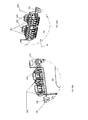
- the connectors 90 are mounted at the edge 14e of the PCB 14 in a straddle manner, e.g., the connectors are configured for contacting corresponding terminals of the contact regions 95 by straddling, thus holding two opposite surfaces of the PCB, as clearly visible for example in figs. 8 , 10a and 10b .
- the opposite surfaces are in this case the active surface 14a and the rear surface 14r of PCB 14.
- PCB 14 includes at least two light sources 71, 72 (visible only in fig. 2 ), mounted on its active surface 14a, apt to emit light which is then visible through the corresponding aligned light indicators 81, 82 on the dashboard 11, so that - for example - status of the appliance or confirmation of the user's program selection is made visible.
- the light indicators 81,82 emits light to render visible information to the user.
- the information given by the illumination of the first light source 71 is preferably different from the information given by the illumination of the second light source 72.
- the light sources 71, 72 are suitable LEDs.
- the LEDs 71, 72 are separated one form the other by a given distance and they can be identical or different, both in intensity and/or color. Many other LEDs and/or different light sources can be present in the PCB 14.
- the control panel assembly 1 further includes a box-like member 12, having the shape of a mounting platform, which includes at least two light guides 91, 92 in order to "guide” the light emitted by the light sources 71, 72 from the PCB 14 to the light indicators 81, 82 on the dashboard 11.
- the light guides 91, 92 are mounted so as to face on one side the respective light sources 71, 72 on the active surface 14a of the PCB 14, and, on the opposite side, the corresponding light indicators 81, 82 in the dashboard 11, so that the light emitted by the light sources 71, 72 can be visible through the dashboard 11 itself, e.g., so that the light produced by the light sources 71, 72 becomes visible for a user resting in front of the appliance.
- the light guides 91, 92 are preferably made of a material which is permeable by light; for example they can be made of a transparent plastic material.
- the box-like member 12 and the light guides 91, 92 can be realized substantially monolithically one to the other, e.g. the box-like member 12 is preferably a single element, for example obtained by plastic molding. In this case, the whole box-like member 12 is made of the same light permeable plastic material.
- the light guides 91, 92 can be made of a light permeable plastic material and then fixed onto the box-like member 12 made of a different material.
- the box-like member 12 has a substantially hollow box shape, for example of the parallelepiped type, with an open side where the PCB 14 is fixed, e.g. the PCB 14 is at least partially housed by box-like member 12 in an assembled configuration of the control panel assembly 1.
- the box-like member 12 is interposed between the dashboard 11 and the PCB 14 when the control panel assembly 1 is in an assembled configuration.
- the box like shape of member 12 preferably surrounds with its front wall 12f and its lateral walls 12s the lateral edge 14e of the PCB 14.
- light guides 91, 92 extend from the front wall 12f, preferably both rearward and outwardly, substantially perpendicularly to the latter.
- the box-like member 12 further includes, at one of its lateral walls 12s, a recessed portion 93 so that the connectors 90 connected to the contact regions 95 at the edge 14e of the PCB 14 can be exposed and easily reachable, in order to make them accessible for proper connection and disconnection to operative loads/power supply of the appliance.
- the light guides 91, 92 preferably have a stem like shape and protrudes from a rear surface of front wall 12f towards the active surface 14a of the PCB 14 and from a front surface of the front wall 12f towards the rear surface 11r of the dashboard 11 so as, as already mentioned, to transport the light emitted by the light sources 71, 72 such as the LEDs, to the light indicators 81, 82.
- the cross section of the stems can be any, for example it can be oval or circular or rectangular.
- the form of the cross section preferably depends on the shape of the light sources 71, 72 and also on the optical effect that it is desired to give to the indicator in the dashboard.
- a different additional light guide is present, therefore for each couple of two distinct light sources separated by a given distance, a couple of two distinct light guides separated substantially by the same distance is preferably present as well.
- box-like member 12 embracing, as mentioned, the PCB 14, may preferably include a plurality of pass-through apertures so that the various push button, knobs, display, etc., operable from the dashboard, contact the active surface 14a of the PCB 14.
- the control-panel assembly 1 includes a light separator element 13, better visible in figs. 5 and 8 , interposed between the PCB 14 and the box-like member 12.
- the light separator element 13 is apt to optically separate the light from the two light sources 71, 72, so that the light from the first light source 71 reaches the first light indicator 81, and the light of the second light source 72 reaches the second light indicator 82, without mixing the two.
- the light separator 13 is used in order to separate the light coming from the different light sources and transported to the light indicators in the dashboard by the light guides, so that the light of each light source remains separated by the light of the other sources, avoiding any mixing and thus confusion for the user.
- Light separator 13 preferably includes at least two opaque sleeves 13c, 13d, one for each light guide 91, 92, each sleeve 13c, 13d defining a corresponding through hole 13a, 13b, respectively.
- the term "opaque" means not transparent, or very slightly transparent, to light emitted by the first and/or second light source 71, 72.
- Sleeve 13c is preferably associated with light guide 91, and sleeve 13d is thus preferably associated with light guide 92.
- the sleeve 13c, 13d surrounds its respective light guide 91, 92 which is inserted in through-hole 13a, 13b.
- the internal surface of each through hole 13a, 13b keeps the light guided in the first or second light guide 91, 92 confined within the sleeve 13c, 13d, respectively.
- the cross section of the through holes 13a, 13b of sleeves 13c, 13d has preferably substantially the same shape as the cross section of the respective light guide 91, 92 which is inserted in the same. Therefore, it can have any desired shape.
- light separator 13 further includes a plate-like member 13e, preferably substantially flat, from which the sleeves 13c, 13d extend.
- the plate 13e includes a first and a second opposite surface 13f, 13g.
- the first surface 13g is substantially in abutment to the active surface 14a of the PCB 14, while the second surface 13f faces the front wall 12f of the box-like element 12.
- the sleeves 13c, 13d protrude from both the first and the second surfaces 13f, 13g outwardly, so that they preferably follow the whole light guides 91, 92 which are inserted into the through holes 13a, 13b for all their longitudinal extension.
- the light separator 13 further includes one or more supporting members 101 for mechanically supporting the connectors 90 and keeping the latter electrically connected with the contact region 95 of the PCB 14.
- the supporting member 101 preferably, but not necessarily, one supporting member 101 for each different connector 90, is located at an edge 113 of light separator 13, so as to be positioned correspondingly to the location of the connectors which are fixed straddle the edge 14e of PCB 14.
- Each one of the supporting member 101 defines a seat for its corresponding connector 90, in addition preferably each seat has preferably a shape matching the shape of the corresponding connector 90.
- supporting member 101 protrudes, after the mounting of the display assembly, beyond the active surface 14a of the PCB 14 towards the rear surface 14r, so that the connector 90 can be supported in an electrically connected mannerion to both contact regions 95 in the active and rear surfaces 14a, 14r.
- the supporting member 101 is preferably substantially C- or U-shaped including a back wall and two arms 102 for supporting and also preferably guiding the connector.
- the supporting member 101 further comprises an elastic clip element 103 fixed to the back wall and configured to snap-fit the connector 90 of the PCB 14.
- the connector 90 is inserted in the C- or U-shaped supporting member 101 and, when completely inserted, is blocked in accidental removals by the clip 103 action.
- the arms 102 of the C- or U-shaped supporting member 101 are, when the panel assembly is in an assembled configuration, preferably abutting against the edge 14e of PCB and substantially perpendicular to both active and rear surface 14a,14r.
- the mechanical coupling may preferably include one or more appendices 88 protruding from the light separator 13 towards the PCB 14.
- the appendices 88 are better visible in figure 5 and 9 , already inserted into the PCB.
- the PCB includes corresponding seats or apertures 89 where appendices can be inserted.
- Appendix 88 can also include a hook so that it is clipped on the edge of the aperture 89.
- the light separator 13 is molded as a single element including the sleeves 13c, 13d and supporting members 101. More preferably, it is made of a material which is not transparent to light.
- the listed elements are advantageously spatially positioned in the listed sequential order, as visible in figure 2 and 5 .
- the outer dashboard 11 can be advantageously provided with one or more protruding appendixes 31 that stick out of the rear surface 11r of the dashboard.
- the appendices 31 stick out in a manner substantially perpendicular to the rear surface 11r.
- PCB 14, light separator 13 and box-like member 12 all includes holes in which, in an assembled configuration, appendices 31 can be inserted.
- light separator 13 is preferably abutted against the active surface 14a of the PCB 14 and therein fixed via appendices 88 aperture 89.
- the two connected PCB and light separator are then housed inside the box-like element 12.
- the box-like element 12 of the light guide is then abutted on the rear surface 11r of the dashboard 11, with appendices 31 going through the mentioned holes in order to avoid relative movements of the components of the control-panel assembly 1.
- the dashboard may advantageously comprise a plurality of pins and teeth which are properly arranged and shaped on the rear surface of the dashboard so as to allow their insertion in corresponding through holes formed in the box-like element and light separator's plate.
- the so-assembled control panel assembly 1 is then coupled to the front wall 4 at the panel aperture 15.
- the PCB 14 and other possible elements are inserted into the aperture 15.
- the outer dashboard 11 is then fastened onto the front wall 4.
- the external portion 11ext preferably remains outside the front wall 4, for example abutting onto the front surface 4a and/or onto the edge 15a of the aperture 15.
- mechanical coupling devices 20, 30 are preferably used, such as screws or snap-fit elements, so that the control panel assembly 1 is attached to the panel aperture 15, and preferably to the edge 15a of the same, in a firm manner, withstanding also possible device's vibrations present during the washing and/or rinsing cycles.
- the outer dashboard 11 is preferably fastened to the crosspiece 66.
- the external portion 11ext of the dashboard 11 is flush-mounted on the front wall 4, being flush with the front surface 4a.
- the aesthetical appearance of the assembled dashboard 11 on the front wall 4 is that of a substantially continuous surface where the external portion 1ext matches the external surface 4a of front wall 4.
- laundry treatment device 100 also includes a detergent drawer 63.
- Detergent drawer 63 is retractably mounted to said front wall 4 so that it can be opened and closed.
- the detergent drawer is generally used to introduce detergents or other products in order to perform a proper washing cycle.
- Detergent drawer includes a detergent drawer front wall 63a, which also remains external to the casing 2 when the laundry treatment device 100 is in an assembled configuration, and it is so shaped to be easily gripped by the user in order to open and/or close the drawer 63.
- Drawer 63 is coupled to drawer aperture 60 of front wall 4.
- a drawer seat 61 is provided, whose dimensions are optimal to house the drawer 63 in a slidable manner.
- the drawer seat 61 is thus fixed to the front wall 4 at the drawer aperture 60.
- Drawer seat 61 is preferably made of plastic material.
- Drawer seat 61 after being mounted on the drawer aperture 60, is then covered by the drawer front wall 63a so that drawer seat becomes substantially invisible when the laundry treatment device 100 is in an assembled configuration.
- Drawer front wall 63a thus is positioned in front of the drawer aperture 60 closing the same.
- the front wall 63a of the drawer is mounted on the drawer seat so that it is substantially flush-mounted on the front wall, i.e., the front surface 4a of the front wall is substantially flush with a front surface of the drawer front wall 63a.
- a single "larger" aperture is provided, as mentioned previously, to house both the control panel assembly 1 and, adjacent to the latter, the detergent drawer 63 (so the crosspiece is not present).
- Drawer seat 61 is inserted into drawer aperture 60 and then fixed to the same.
- for example mechanical coupling can be used.
- drawer seat 61 and the external portion 11ext of the outer dashboard 11 form an integral piece.
- the drawer seat and the dashboard are separated elements one from the other and independently fixed.
- the external portion 11ext of the dashboard 11 and drawer seat 61 are molded together and are made of plastic material.
Landscapes
- Engineering & Computer Science (AREA)
- Textile Engineering (AREA)
- Detail Structures Of Washing Machines And Dryers (AREA)
Abstract
The invention is relative to a laundry treatment device (100) having a casing (2) and a control-panel assembly (1) for controlling operation of the laundry treatment device, said assembly (1) comprises:
- a printed circuit board (14) including a first and a second light source (71,72) located at a given distance one from the other, said first and second light sources being apt to emit a first and second light, respectively;
- an electrical connector (90) fixed or fixable to a contact region (95) of said printed circuit board (14) for allowing connection thereof to one or more operative loads of the laundry treatment device (100) and/or to an electrical power supply;
- an outer dashboard (11) which is structured to be coupled to the casing of the laundry treatment device (100) and operable by a user, said outer dashboard (11) including a first and a second light indicator (81,82) to visualize the first and second light coming from said first and second light sources, respectively;
- a first and a second light guide (91,92) interposed between said printed circuit board (14) and said outer dashboard (11) to guide the first and second light from said first and second light sources (71,72) towards said first and second light indicator (81,82), respectively; and
- a light separator (13) interposed between said printed circuit board and said outer dashboard to optically separate the first light emitted by said first light source (71) from the second light emitted by said second light source (72), so that in said first light indicator (81) substantially only said first light is visible and in said second indicator (82) substantially only said second light is visible.
- a printed circuit board (14) including a first and a second light source (71,72) located at a given distance one from the other, said first and second light sources being apt to emit a first and second light, respectively;
- an electrical connector (90) fixed or fixable to a contact region (95) of said printed circuit board (14) for allowing connection thereof to one or more operative loads of the laundry treatment device (100) and/or to an electrical power supply;
- an outer dashboard (11) which is structured to be coupled to the casing of the laundry treatment device (100) and operable by a user, said outer dashboard (11) including a first and a second light indicator (81,82) to visualize the first and second light coming from said first and second light sources, respectively;
- a first and a second light guide (91,92) interposed between said printed circuit board (14) and said outer dashboard (11) to guide the first and second light from said first and second light sources (71,72) towards said first and second light indicator (81,82), respectively; and
- a light separator (13) interposed between said printed circuit board and said outer dashboard to optically separate the first light emitted by said first light source (71) from the second light emitted by said second light source (72), so that in said first light indicator (81) substantially only said first light is visible and in said second indicator (82) substantially only said second light is visible.
In addition, said light separator (13) includes a supporting member (101) for mechanically supporting said electrical connector (90) to keep the latter electrically connected to said contact region (95) of said printed circuit board (14).
Description
- The present invention generally relates to a laundry treatment device, such as front/top loading washing machines, washers/dryers, dryers, both for domestic and professional use. More particularly, the present invention relates to a laundry treatment device including a control-panel assembly.
- Each household and professional laundry treatment device (hereinafter, appliance, for the sake of conciseness) -such as washing machine, washer/dryer, dryer- typically comprises a substantially parallepiped-shaped cabinet enclosing an inner compartment for housing items to be treated (e.g., laundry to be washed and/or dried), an access door for accessing the inner compartment thereby allowing loading/unloading operations of the items by a user, and a manually-operable dashboard (typically including control members, also called input devices, e.g., rotatable knobs, display devices, buttons, switches and the like) for allowing the user to manually control operation of the appliance and ascertain an operational state thereof.
- As known, the dashboard represents an exposed part of a control-panel assembly, which typically is connected to an inner printed circuit board (or PCB) that is electrically connected to electronic components and the control members associated therewith for implementing corresponding control functionalities, e.g. powering, driving, activation, deactivation of operative loads including electric, electronic, electro-mechanical and/or electro-hydraulic parts of the appliance (such as motor, solenoid valve, further PCBs and the like).
- In order to achieve that, the PCB is typically coupled with the operative loads to be controlled, and to an electrical power supply, by means of one or more electrical cables or wires provided with electrical connectors (in the following, connectors, configured in such a way to be properly mounted on the PCB for contacting respective electrical terminal - or terminals - of the electronic components on the PCB), so as to mechanically and electrically joining the PCB to one or more of the operative loads which the PCB has to be connected to and/or to the electrical power supply.
- As known, many design efforts by laundry appliances manufacturers are directed to provide firm and easy mounting of the connectors on the PCB, as well as ensure accessibility thereof for proper connection of the PCB with the operative loads and electrical power supply.
- Among the known techniques, connectors are mounted on an edge of the PCB by means of mechanical pressure. For example, the connectors could be straddle-mounted the edge of the PCB and they are fixed therein by the pressure necessary to slot the connector in the PCB.
- However, it is known that laundry treatment devices are subjected to vibrations, due for example to the rotation of the drum during the washing and/or rinsing cycles. Continuous vibrations can easily cause detachment of the pressure-coupled connectors from the PCB, which in turn causes a malfunctioning of the laundry treating device.
- Alternatively, it is known to fix the connectors on the PCB by soldering. Although soldering resists vibrations, it is a permanent connection, in other words it is not possible to detach and re-couple again the connectors in a simple manner. Indeed, the mounting and dismounting of the connectors could be needed in case of repair and maintenance of the device.
- Applicant has realized that the known devised and practiced solutions are not satisfactory for modern technological requirements.
- In fact, according to Applicant, the approach providing the connectors fixed/held to the PCB by soldering or mechanical pressure could not be sufficiently effective and reliable, as above described.
- In addition, Applicant has realized that costs are also a decisive factor for the success of a laundry treatment appliance, therefore introducing further elements in the construction of the laundry treatment device could most probably increase the costs of the same. Increasing the number of components of the device not only increases costs, but also the time required for the device overall assembly, and the numbers of spare parts to make available.
- Last but not least, changes in the layout of a "standard" device causes great influence on production, warehousing and managing cost of the control-panel assembly, and hence of the appliance.
- Applicant has tackled the problem of devising a satisfactory solution able to overcome the above-discussed drawbacks.
- According to a first aspect, the invention relates to a laundry treatment device having a casing and a control-panel assembly for controlling operation of the laundry treatment device, said assembly comprises:
- a printed circuit board including a first and a second light source located at a given distance one from the other, said first and second light sources being apt to emit a first and second light, respectively;
- an electrical connector fixed or fixable on a contact region of said printed circuit board for allowing connection thereof to one or more operative loads of the laundry treatment device and/or to an electrical power supply;
- an outer dashboard which is structured to be coupled to the casing of the laundry treatment device and operable by a user, said dashboard including a first and a second light indicator to visualize the first and second light coming from said first and second light sources, respectively;
- a first and a second light guide interposed between said internal printed circuit board and said outer dashboard to guide the first and second light from said first and second light source towards said first and second light indicator, respectively;
- a light separator interposed between said printed circuit board and said outer dashboard to optically separate the first light emitted by said first light source from the second light emitted by said second light source, so that in said first light indicator substantially only said first light is visible and in said second indicator substantially only said second light is visible;
- Preferably, the laundry treatment device is a washing device or a dryer or a washer-dryer.
- Most preferably, it is a front loading laundry treatment device.
- The laundry treatment device includes a casing delimiting the appliance. Generally, the casing includes a front wall and a top wall.
- The control panel assembly is manually operated by a user in order to select one or more of the available programs for the laundry treatment or to input any data relative to the functioning of the appliance. The control panel assembly can also display warning messages or instruction for maintenance coming directly from the household appliance.
- The control panel assembly can be coupled to any portion of the casing of the laundry treatment device, for example typically to the front wall or the top wall, depending whether the laundry treatment device is of the front loading or top loading type.
- Preferably, the front/top wall and the dashboard are made of different materials. For example, the front/top wall is made of metal and the dashboard of plastic material.
- Advantageously, the outer dashboard defines an outer surface which, in an assembled configuration, preferably substantially forms a geometrical continuation of a front surface of the front wall or top wall (depending on where the panel assembly is coupled to), e.g., it does not protrudes or sticks out in a significant manner, but it is substantially flush to the same, so that the front wall globally has a pleasant aesthetical appearance.
- It is common that the outer dashboard includes light indicators in order to control operation of the laundry treatment device or issue possible warning messages directed to the user or to the repair technician. Light indicators can also be used to show the program(s) which have been selected by the user. Light indicators include generally openings formed in the dashboard, for example covered by a transparent material, which show light coming from light sources present in the printed circuit board located at the light indicators. Alternatively, the material of the dashboard at the light indicators could be substantially transparent to light.
- Preferably, the light sources include LEDs, which could be advantageously designed to emit colored light, preferably also in different colors, and/or with different intensities. In this configuration, each LED is apt to illuminate its corresponding light indicator present in the dashboard with light of a different color/intensity with respect to light reaching another light indicator so that different information could be displayed and become evident to the user. For example, the indicators relative of warning messages and/or malfunctioning of the device could be illuminated in red, while the indicators relative to the status of the device (e.g., washing, rinsing, spinning, etc.) could be colored in green. Alternatively, all LEDs present in the printed circuit board emit light having substantially the same color and/or intensity.
- In order to "transport" light from the light sources in the printed circuit board to the openings (or transparent area) of the corresponding light indicators on the dashboards, light guides are used, one for each light source, which transport the light emitted by the light sources from the printed circuit board to the dashboard. Light guides could for example include light transparent rods having one end abutting on the light source and the other end abutting on the corresponding light indicator.
- In order not to mix the light coming from different light sources, i.e., in order to visualize in each light indicator on the dashboard substantially only the light of a corresponding light source programmed to emit light under certain conditions, so as not to confuse the user (for example, in case the light of one light source illuminates two indicators, the user cannot understand which information is meant to be given), a light separator is commonly employed. Light separator optically separates light coming from each light source, so that each light indicator in the dashboard is shone substantially only by the light of its corresponding light source.
- Light separator separates light from one light source to the other(s) for a given optical path, e.g. for a given distance, this distance being preferably the distance separating the printed circuit board to the outer dashboard. Then, at the outside, the light emitted from the light sources can merge.
- All electrical and mechanical inputs which are inputted by the user on the dashboard via knobs, buttons, touch screens and others which are then electrically transmitted to the printed circuit board, have as consequence an action of the laundry treatment device, e.g. it starts, stops, changes rotational speed, starts a specific program, etc. In order to perform these actions, the printed circuit board is connected through one or more electrical connectors to electric loads of the device, such as the motor of the same and/or to a power supply. The electrical connector is fixed to the printed circuit board and it is in contact with terminals formed on the same. The terminals are formed on a contact region of the printed circuit board. In order to assure a firm coupling between the connector and the printed circuit board, according to the invention a supporting member is provided, to support the connector on the contact region so that it stays electrically connected to the same. In order to avoid introducing further elements into the control panel assembly, the light separator is used to carry such supporting member, e.g. the body of the light separator also includes the supporting member.
- Preferably, said contact portion is formed substantially in proximity of an edge of said printed circuit board and said supporting member is formed in a corresponding edge of said light separator.
- The electrical connector is preferably reachable by the user or by a technician, and more preferably in an easy manner when the control panel assembly is detached from the casing of the laundry treatment device. For this purpose, it is preferred to locate the connector, and thus the supporting member, in an edge of the printed circuit board/light separator, so that, when the control-panel assembly is disconnected from the casing of the laundry treatment appliance, no further disassembly is required.
- Preferably, said printed circuit board includes an active surface and a rear surface opposite to the active surface, said terminal portion being formed in both said active and said rear surface.
- A wide region with terminals assures a better electrical contact between the printed circuit board and the connector.
- The active surface of the printed circuit board is defined as the surface in which conductive pathways, tracks or signal traces are formed. Generally all these conductive pathways and tracks are etched from copper sheets laminated onto a non-conductive substrate. On this surface also the light sources are present.
- More preferably, said printed circuit board includes an active surface and a rear surface opposite to the active surface, said light separator faces said active surface, and said supporting member, after the mounting of the control-panel assembly, protrudes beyond said active surface toward said rear surface of the printed circuit board and forms a seat for guiding the electrical connector to the contact region.
- Because the contact region is located on both opposite surfaces of the printed circuit board, in order to assure a proper support of the connector in such a region, it is preferred that the supporting element is also extending beyond both sides of the printed circuit board.
- Preferably, said supporting member includes a C- or U-shaped member having a shape substantially matching at least part of the shape of said electrical connector for guiding the electrical connector in said contact region.
- The supporting member can thus firmly mechanically hold the connector between the arms of the C- or U-shaped member.
- Advantageously, said supporting member includes an elastic clip element to hold said electrical connector within said supporting member.
- In addition to simply holding the connector, the supporting element also elastically blocks the latter inside the C- or U-shaped member to improve the stability of the connection between the connector and the contact region.
- In a preferred embodiment, said printed circuit board includes an active surface and a rear surface opposite to the active surface, said electrical connector is configured so as to be mounted straddle said active surface and rear surface of said printed circuit board, and said supporting member is extending from said active surface to said rear surface bridging an edge of said printed circuit board for guiding the straddle-mounted electrical connector both at the active surface and at the rear surface.
- Advantageously, said C- or U-shaped member is substantially perpendicular to said active surface and/or rear surface and it is abutting against the edge of said printed circuit board.
- The straddle mounted connector, which is straddle the rear and active surface, is kept in place by the C- or U-shaped member which is located on the edge of the printed circuit board holding the connector on the two surfaces.
- Advantageously, the panel control assembly includes a box-like member interposed between said printed circuit board and said outer dashboard, said box-like member having a front wall and side walls, said first and second light guides protruding from said front wall, said box like member including a recessed area in one of its side walls for exposing said electric connector and allowing connection thereof with one or more loads of said laundry treatment device.
- The box-like member has the function of protection of the printed circuit board. Again, to reduce the number of different pieces which need to be assembled to form the control panel assembly, the light guides are integral to the box-like member. For example, the box-like member can be molded as a single piece of plastic, more preferably, it is made of a transparent plastic material, so that it can guide light.
- Preferably, said light separator includes at least a first and a second through-holes, a first and second aperture of said first and second through-holes being superimposed to, when said control-panel assembly is mounted, said first and second light source, respectively, said first and second through-holes further including a first and second inner surface, respectively, guiding the first and second light emitted by said first and second light sources in a separate manner.
- More preferably, said first and second light guides are inserted in said first and second through-holes, respectively.
- In this way, the guiding and separation of light coming from different sources is performed in an effective and reliable way.
- Said light separator in a depicted embodiment is a monolithic element.
- Therefore, in this embodiment the light separator can be molded as a single piece together with the guiding element. It is indeed preferred that the number of parts of the panel assembly are as little as possible so that the assembly is quick and easy reducing mounting costs and time.
- Moreover, the plastic material in which the light separator is formed is preferably flexible enough to form a supporting member substantially elastic and thus supporting the connectors in the right position, e.g. so that the connectors are electrically connected to the contact region(s), also when the laundry device vibrates.
- In an advantageous embodiment, said light separator is coupled to said printed circuit board by means of at least an appendix provided in one of said light separator and printed circuit board housed in a corresponding seat formed in the other of said light separator and printed circuit board.
- It is preferred that the light separator is directly coupled to the printed circuit board in an easy manner so that undesired relative movements between the light separator and the printed circuit board, and thus of the connectors, are minimized. In this way, the guiding member and the connector are substantially a single rigid block.
- Preferably, said light separator is made of a plastic material not transparent to said first and second light.
- Advantageously, the light separator is a piece of molded plastic which is not transparent to light (or at least to a very minor extent) so that it can be produced in a rather economical manner and at the same time can be effective in separating the light from the different light sources.
- Preferably, said casing includes a front wall defining a continuous front surface having a panel aperture, said control-panel assembly being coupled to said panel aperture.
- In this preferred embodiment, the front wall of the casing has a front surface which is a continuous surface having at least an aperture which is called panel aperture. This front surface represents the external front surface of the appliance and it is construed as a single continuous surface holed by the panel aperture. In other words, there is a single piece of front wall which hosts, via appropriate opening, a control panel assembly. "Single piece" means that there are no junctions or seams in the front surface connecting different pieces together. These front walls are in jargon also called "full front". However, the front wall can also include additional element(s) separated from the portion of the front wall defining the continuous front surface. As an example, the front wall could include a first portion having a panel aperture to host the control-panel assembly which is positioned in the top-most part of the front wall, and a second portion, separated from the first, which covers the lowermost part of the front wall.
- Further features and advantages of the present invention shall become clearer from the following detailed description of a preferred embodiment thereof, made with reference to the attached drawings and given as an indication and not for limiting purposes.
- In particular, the attached drawings are included to provide a further understanding of the invention and are incorporated in and constitute a part of this specification. The drawings together with the description explain the principles of the invention. In the drawings, corresponding characteristics and/or components are identified by the same reference numbers. In such drawings:
-
figure 1 schematically shows a perspective view of a laundry treatment device according to the invention; -
figure 2 shows a perspective view of the laundry treatment device offig. 1 wherein the panel control assembly is in a disassembled configuration; -
figure 3 shows a perspective view of a casing of the laundry treatment device offigs. 1-2 in a disassembled configuration; -
figure 4 is a front view of the casing offig. 3 ; -
figure 5 shows a perspective view of the panel control assembly in a disassembled configuration; -
figure 6 shows a perspective view of the panel control assembly offig. 5 in an assembled configuration; -
figure 7 shows a back view of the panel control assembly offig. 6 ; -
figure 8 shows a perspective view of two elements of the panel control assembly offigs. 5-7 ; -
figure 9 shows a front view of a component of the element offig. 8 ; -
figures 10a and 10b show two different perspective views of a detail, in an enlarged view, of an element of the panel control assembly offigs. 5-7 . - Referring to the drawings,
Figure 1 schematically shows a perspective view of alaundry treatment device 100 according to the present invention. - As it will be better understood by the following description, the teaching of the present invention may be applied to substantially any appliance for laundry treatment, e.g., to washer/dryers, washing machines (as exemplary illustrated in the figures and to which reference will be made in the following by way of a non-limiting example only), dryers (e.g. tumble dryers), etc.
- With reference to
figs. 1 and2, thedevice 100 comprises a, preferably substantially parallelepiped-shaped,casing 2, which encloses an inner compartment comprising a laundry treatment chamber, for example a rotating drum 12' for housing the laundry to be treated and a tub encasing the drum (tub is not visible in the appended drawings). - Moreover, the device includes an
access door 3 provided on afront wall 4 for accessing the laundry treatment chamber 12' thereby allowing loading/unloading of the laundry by a user. Thecasing 2 preferably also includes a bottom wall orbasement 7, atop wall 6, a back wall (not visible), and two opposite lateral walls (only one of the two visible infigures 1 and2 ) 9. Preferably, lateral walls, front walls, top wall and basement are separated pieces which are then assembled together via suitable fastening means. However, it is also encompassed by the present invention that some of these walls can be a single piece, for example lateral walls and back wall can be a single C- or U-shaped piece. Walls are preferably made of metal, however also plastic is possible. Also, in a non-depicted embodiment, some of the walls can be made of a material, and some other(s) can be made of a different material. - By the
device 100 itself, in a standard operative position, a horizontal plane is defined (plane (XY) inFigure 1 ), which is generally the plane on which the bottom wall orbasement 7 lies and generally it is also parallel to thetop wall 6 of the casing in a mounted configuration. The appliance also extends along a vertical direction denoted with Z (seeFigure 1 ). - In a preferred embodiment, the
front wall 4 includes an externalcontinuous surface 4a having a plurality of apertures, as better detailed below. According to a preferred embodiment, the front external surface is the external front surface of the appliance. -
Front wall 4 is preferably made of a metallic material, for example in stainless steel. - The
front surface 4a is preferably continuous and even more preferably seamless, at least in the visible portion(s) of the same. Continuous surface means that the surface is formed as a single member. "Seamless" means that, in addition to be continuous, there are no seams which indicate that for example welding has been used to join together different parts. In the covered (i.e. not visible from outside thelaundry treatment device 100 in the assembled condition of the latter) portions of thefront wall 4, seams can be present. The absence of seams improves the overall appearance of thelaundry treatment device 100. - In addition, the
front wall 4 preferably includes four roundedcorners device 100, and they also make the use of the device safer for the user, which could be injured by sharp corners - In an embodiment of the invention, the
front wall 4 can be obtained by a single sheet of metal. For example, it can be obtained by a sheet of stainless steel. In addition, the front wall can be coated by suitable coating to prevent corrosion. Moreover, the front wall can be colored of any color and gloss. - Preferably, the
front wall 4 defines atop portion 4a', amiddle portion 4a"' and abottom portion 4a", the terms "top", "middle" and "bottom" used with reference to the standard standing configuration of the household appliance when in use. - In a preferred embodiment, not depicted in the drawings, only the
top portion 4a' and themiddle portion 4a"' of thefront wall 4 are a single (or one-piece) element, i.e., having a continuous and/or seamlessfront surface 4a, while thebottom portion 4a" can be permanently fixed to it, for example welded to it, or it can even be added as an additional element which can be disassembled from the rest of the front wall. - In addition, the
front wall 4 includes an outer edge which can be divided in atop edge 50a, which is the portion of the outer edge comprised betweencorners bottom edge 50b, which is the portion of the edge located betweencorners corners -
Front surface 4a includes alaundry opening 3a for the access into thelaundry treatment device 100, in particular to the laundry treatment chamber 12' so that laundry can be loaded or unloaded to/from thelaundry treatment device 100. Theopening 3a is openable and closable by thedoor 3, which is advantageously hinged tofront wall 4. - Preferably, the
door 3 is coupled to a recessedportion 3b of the front wall 4: in this embodiment, thefront wall 4 includes the recessed portion (seefigures 3 and4 ) in the center of which thedoor opening 3a is formed. The dimensions of theopening 3a are such to be suitable to accommodate thedoor 3. Thedoor 3 is then rotatably coupled to thedoor opening 3a and, when mounted and in a closed position, it preferably does not project substantially beyond thefront surface 4a due to the recess presence. In other words, an outer surface ofdoor 3 matches thefront surface 4a offront wall 4. - Preferably, but not necessarily, the
door 3 and the recessedportion 3b are located in themiddle portion 4a"' of the front wall. - Advantageously, the
front wall 4 is not flat, i.e., it does not lie completely on a single plane. On the contrary, it includes a concavity pointing, in the assembled configuration, towards the inside of thecasing 2, being convex on the outside. In the depicted embodiment, the front wall 4 - in a section along a plane parallel to plane YZ- has substantially a smoothed trapezoidal shape, the top 4a', the bottom 4a" and themiddle portion 4a"' substantially lying on three different planes which form an angle one with respect to the other(s) and also with the vertical direction Z defined by thecasing 2, forming in this way the inward concavity. The three planes are preferably connected smoothly and without sharp corners. However, other layouts of thefront wall 4 are possible as well, for example the front wall can include a substantially constant curvature, the concavity still oriented towards the inside of the casing. For example, the front wall could be a portion of a cylindrical mantel. - Preferably, a first and a
second side walls front wall 4, extend from itsside edges corners 4b-4e and 4c-4d, respectively. When the laundry treatment device is in an assembled configuration, i.e., when all elements of thecasing 2 are mounted, theside walls casing 2. More preferably,side walls front wall 4 are formed continuously as one body, i.e., they are not an assembly of different pieces but they are integral one to the others, and more preferably there are no seams of welding separating the front from the side walls. Side walls and front wall are thus formed as a single piece and even more preferably thefront surface 4a of thefront wall 4 is smoothly connected to the front surfaces of theside walls - Preferably, also an
upper wall 6a and abottom wall 7a extend from the top and bottom edge, 50a and 50b, respectively, of thefront wall 4. Preferably,upper wall 6a andbottom wall 7a are continuous with the front wall. In this way,corners - The two
side walls front wall 4 substantially perpendicularly to thefront wall 4 towardslateral walls 9, so as to be aligned to the latter. Analogously, also upper andbottom walls top edge 50a andbottom edge 50b substantially perpendicularly to thefront wall 4, respectively towards the top andbottom walls bottom wall 7a andside walls front wall 4 to the rest of thecasing 2. - Further,
front wall 4 includes asecond aperture 15, called panel aperture. Preferably, thefront wall 4 includes also a third aperture, calleddrawer aperture 60. - Preferably, the
panel aperture 15 and/or thedrawer aperture 60 is (are) located at thetop portion 4a' of the front wall. - In a preferred embodiment, better visible in
figs. 3 and4 , thepanel aperture 15 and thedrawer aperture 60 are each substantially a through hole within the front wall, in other words the panel aperture and/or the drawer aperture is(are) completely surrounded in all directions by thefront wall 4. In this way, thepanel aperture 15 and/or thedrawer aperture 60 includes each an outer edge, 15a and 60a, respectively, which defines a closed curve, such as a loop. - Preferably,
panel aperture 15 anddrawer aperture 60 are located one adjacent to the other substantially at the same height along the Z direction on thefront wall 4. - A bridging
crosspiece 66 advantageously separates thepanel aperture 15 from the drawer aperture 60 (and vice-versa). As visible in the figures, preferably thecrosspiece 66 has an elongated shape and has a longitudinal extension substantially parallel to the vertical axis Z.Crosspiece 66 includes a portion of theedge 60a of thedrawer aperture 60 and a portion of theedge 15a of thepanel aperture 15a, corresponding to its longitudinal opposite edges. Furthermore,crosspiece 66 includes afront surface 66a which is oriented towards the outside of thecasing 2. - In a preferred embodiment, the
front surface 66a of thecrosspiece 66 and thefront surface 4a of thefront wall 4 are a continuous uniform surface, and even more preferably this continuous uniform surface is also seamless. In this case, thecrosspiece 66 is substantially an integral part of the front wall 4: in thefront wall 4 there are two apertures, the drawer and panel aperture, and the crosspiece is the "remaining" portion of front wall 4 (for example during a punching procedure of a metal sheet for obtaining the apertures) between the two. - In a different embodiment, not visible in the drawings, the
crosspiece 66 is attached, for example by means of its oppositelongitudinal ends apertures front wall 4. - In a different embodiment, not shown in the figures, drawer aperture and panel aperture might be the same aperture, e.g., a single "bigger" aperture can be obtained on the front wall, having the function of the panel and drawer apertures.
- Preferably, but not necessarily, the front wall may comprise a
service aperture 99, (shown only infigure 1 ) preferably covered by aservice aperture cover 99a, so that a filter (not visible) of thelaundry treatment device 100 might be easily accessible. Preferably, theservice aperture 99 is provided at thebottom portion 4a" of thefront wall 4. -
Laundry treatment device 100 further includes apanel control assembly 1. - In
figures 1 ,2 ,5 ,6 and 7 , an exemplarycontrol panel assembly 1 in accordance to the invention is shown. Thecontrol panel assembly 1 includes anouter dashboard 11, which in the depicted embodiment spans for most of the width of thefront surface 4a of the appliance. Preferably, although not necessarily, thedashboard 11 is substantially a basin-shaped rigid shell. Preferablydashboard 11 is structured for being coupled to the outerfront wall 4 of the appliance. Preferably, thedashboard 11 is made of plastic material. - The
dashboard 11 is preferably configured for allowing the user to manually control operation of the appliance and ascertain an operational state thereof. The dashboard includes a portion 11ext, external to thecasing 2 whenlaundry treatment device 100 is in the assembled condition (as shown infigure 1 ), which is the portion of thedashboard 11 visible and operable by the user. The dashboard external portion 11ext is an exposed part of the control panel assembly also when thedevice 100 is fully assembled. The dashboard external portion 11ext advantageously includes a plurality of apertures and/orinput areas 38 through which manually-operable control members 38a are visible or operable. - For example, received within, or in registry with, the
various apertures 38 formed in the dashboard external portion 11ext, there are a main push button used as a main power control, a plurality of operation push-buttons, control knobs and illumination elements. Although not depicted, the dashboard external portion 11ext might include also a display screen and one or more control knobs. - The control knob might be rotatable in order to permit the user to select operation cycle settings and other control parameters, with reference to selections indicated by words, icons or other indicia that may be arranged, in printed form or on a display or otherwise, on the dashboard.
- At least two further apertures in the dashboard, in the following called
light indicators - In the depicted embodiment, the
dashboard 11 advantageously includes several arrays of apertures fordifferent light indicators different light indicators - Push buttons, display and apertures to visualize light indicators are known in the art and will not be further detailed below.
-
Outer dashboard 11 also includes arear surface 11r facing theinternal casing 2, whendevice 100 is in an assembled configuration. In the latter configuration, therear surface 11r is located in front of thepanel aperture 15 substantially covering (or overlapping) the same.Rear surface 11r is preferably substantially flat. - Referring now to
figures 2 and5 , it is shown a perspective exploded view of thecontrol panel assembly 1. As visible from the figures, thecontrol panel assembly 1 also includes a printed circuit board (PCB) 14 for electrically connecting, on a correspondingactive surface 14a (shown for example infigure 8 ) thereof, the rotatable knobs, and/or the buttons, and/or the display, etc., mentioned with reference to the dashboard. - Moreover, as generally known in the art, the PCB electrically connects functional components, e.g., electronic circuitry components (not visible in the figures), and to an electrical power supply, for implementing corresponding control functionalities of the control panel assembly. Such functionalities can be one or more of powering, driving, activation, deactivation of one or more operative load including electric, electronic, electro-mechanical and/or electro-hydraulic parts of the appliance, such as motor(s), solenoid valve(s), further PCB, all not shown.
- In this respect, the
laundry treatment device 100 comprises one or moreelectrical connectors 90 apt to be fixed to acorresponding contact region 95 of thePCB 14 for allowing connection thereof to the mentioned loads/power supply. Contactregion 95 can include a single region, or a plurality of regions spatially separated one from the other(s). Advantageously, for eachconnector 90, acontact region 95 is allocated. Preferably, at least part of thecontact region 95 is part of theactive surface 14a of thePCB 14. Even more preferably, at least another part of thecontact region 95 is realized on arear surface 14r ofPCB 14. - In
contact region 95, terminals are present in order to obtain the desired connection toconnectors 90. -
PCB 14 is connected to therear surface 11r once the control panel assembly is in an assembled configuration, and when the control panel assembly is mounted oncasing 2, it is located internally to thecasing 2. - Preferably, the
active surface 14a of the printedcircuit board 14 faces therear face 11r of theouter dashboard 11. The printed circuit board is arranged on therear face 11r of the dashboard, preferably so that each display device and manually operatedinput device 38a (the knobs, push buttons, light elements above described with reference to the dashboard) of the board is aligned to and engage acorresponding opening 38 or seat of thedashboard 11. - Preferably, but not necessarily, the printed
circuit board 14 is arranged locally substantially parallel to therear face 11r of thedashboard 11. - As shown in the depicted drawings, preferably the
contact region 95 including the terminals is located close to the boundary of theactive surface 14a, e.g., preferably it is located in proximity of anedge 14e of theactive surface 14a and/orrear surface 14r. - Consequently, preferably, the
connectors 90 are coupled to theedge 14e of thePCB 14, allowing an easier removal of the same without the need of disassembling the whole control-panel assembly. - The coupling of the
connectors 90 to thePCB 14 is preferably of a removable type. For example,connectors 90 are fixed to theirrespective contact regions 95 and they can be afterwards removed. Moreover, thePCB 14 may also include further connectors which are hard mounted, i.e., fixed such as glued or soldered, onPCB 14. - In the depicted embodiment, the
connectors 90 are mounted at theedge 14e of thePCB 14 in a straddle manner, e.g., the connectors are configured for contacting corresponding terminals of thecontact regions 95 by straddling, thus holding two opposite surfaces of the PCB, as clearly visible for example infigs. 8 ,10a and 10b . The opposite surfaces are in this case theactive surface 14a and therear surface 14r ofPCB 14. - Preferably,
PCB 14 includes at least two light sources 71, 72 (visible only infig. 2 ), mounted on itsactive surface 14a, apt to emit light which is then visible through the corresponding alignedlight indicators dashboard 11, so that - for example - status of the appliance or confirmation of the user's program selection is made visible. In other words, thelight indicators - For example, the light sources 71, 72 are suitable LEDs. The LEDs 71, 72 are separated one form the other by a given distance and they can be identical or different, both in intensity and/or color. Many other LEDs and/or different light sources can be present in the
PCB 14. - The
control panel assembly 1 further includes a box-like member 12, having the shape of a mounting platform, which includes at least twolight guides PCB 14 to thelight indicators dashboard 11. In other words, the light guides 91, 92 are mounted so as to face on one side the respective light sources 71, 72 on theactive surface 14a of thePCB 14, and, on the opposite side, the correspondinglight indicators dashboard 11, so that the light emitted by the light sources 71, 72 can be visible through thedashboard 11 itself, e.g., so that the light produced by the light sources 71, 72 becomes visible for a user resting in front of the appliance. - Therefore, the light guides 91, 92 are preferably made of a material which is permeable by light; for example they can be made of a transparent plastic material. Preferably, the box-
like member 12 and the light guides 91, 92 can be realized substantially monolithically one to the other, e.g. the box-like member 12 is preferably a single element, for example obtained by plastic molding. In this case, the whole box-like member 12 is made of the same light permeable plastic material. Alternatively, the light guides 91, 92 can be made of a light permeable plastic material and then fixed onto the box-like member 12 made of a different material. - In a preferred embodiment, the box-
like member 12 has a substantially hollow box shape, for example of the parallelepiped type, with an open side where thePCB 14 is fixed, e.g. thePCB 14 is at least partially housed by box-like member 12 in an assembled configuration of thecontrol panel assembly 1. The box-like member 12 is interposed between thedashboard 11 and thePCB 14 when thecontrol panel assembly 1 is in an assembled configuration. The box like shape ofmember 12 preferably surrounds with itsfront wall 12f and itslateral walls 12s thelateral edge 14e of thePCB 14. - Preferably, light guides 91, 92 extend from the
front wall 12f, preferably both rearward and outwardly, substantially perpendicularly to the latter. - The box-
like member 12 further includes, at one of itslateral walls 12s, a recessedportion 93 so that theconnectors 90 connected to thecontact regions 95 at theedge 14e of thePCB 14 can be exposed and easily reachable, in order to make them accessible for proper connection and disconnection to operative loads/power supply of the appliance. - The light guides 91, 92 preferably have a stem like shape and protrudes from a rear surface of
front wall 12f towards theactive surface 14a of thePCB 14 and from a front surface of thefront wall 12f towards therear surface 11r of thedashboard 11 so as, as already mentioned, to transport the light emitted by the light sources 71, 72 such as the LEDs, to thelight indicators - Preferably, for each additional light source present in the
PCB 14, a different additional light guide is present, therefore for each couple of two distinct light sources separated by a given distance, a couple of two distinct light guides separated substantially by the same distance is preferably present as well. - Furthermore, the box-
like member 12, embracing, as mentioned, thePCB 14, may preferably include a plurality of pass-through apertures so that the various push button, knobs, display, etc., operable from the dashboard, contact theactive surface 14a of thePCB 14. - Moreover, according to the invention, the control-
panel assembly 1 includes alight separator element 13, better visible infigs. 5 and8 , interposed between thePCB 14 and the box-like member 12. Thelight separator element 13 is apt to optically separate the light from the two light sources 71, 72, so that the light from the first light source 71 reaches thefirst light indicator 81, and the light of the second light source 72 reaches the secondlight indicator 82, without mixing the two. - In other words, the
light separator 13 is used in order to separate the light coming from the different light sources and transported to the light indicators in the dashboard by the light guides, so that the light of each light source remains separated by the light of the other sources, avoiding any mixing and thus confusion for the user. -
Light separator 13 preferably includes at least twoopaque sleeves light guide sleeve hole Sleeve 13c, is preferably associated withlight guide 91, andsleeve 13d is thus preferably associated withlight guide 92. Preferably when the control-panel assembly 1 is in an assembled configuration, thesleeve light guide hole hole light guide sleeve - The cross section of the through
holes sleeves light guide - Preferably,
light separator 13 further includes a plate-like member 13e, preferably substantially flat, from which thesleeves plate 13e includes a first and a second opposite surface 13f, 13g. Preferably the first surface 13g is substantially in abutment to theactive surface 14a of thePCB 14, while the second surface 13f faces thefront wall 12f of the box-like element 12. Thesleeves holes - According to the invention, the
light separator 13 further includes one or more supportingmembers 101 for mechanically supporting theconnectors 90 and keeping the latter electrically connected with thecontact region 95 of thePCB 14. - In this preferred embodiment, the supporting
member 101, preferably, but not necessarily, one supportingmember 101 for eachdifferent connector 90, is located at anedge 113 oflight separator 13, so as to be positioned correspondingly to the location of the connectors which are fixed straddle theedge 14e ofPCB 14. Each one of the supportingmember 101 defines a seat for its correspondingconnector 90, in addition preferably each seat has preferably a shape matching the shape of the correspondingconnector 90. - Being the connector straddle-mounted, in order to support the latter on both
sides PCB 14, it is preferred that from theedge 113, supportingmember 101 protrudes, after the mounting of the display assembly, beyond theactive surface 14a of thePCB 14 towards therear surface 14r, so that theconnector 90 can be supported in an electrically connected mannerion to bothcontact regions 95 in the active andrear surfaces - The supporting
member 101 is preferably substantially C- or U-shaped including a back wall and twoarms 102 for supporting and also preferably guiding the connector. Preferably, the supportingmember 101 further comprises anelastic clip element 103 fixed to the back wall and configured to snap-fit theconnector 90 of thePCB 14. In other words, preferably theconnector 90 is inserted in the C- or U-shaped supportingmember 101 and, when completely inserted, is blocked in accidental removals by theclip 103 action. - The
arms 102 of the C- or U-shaped supportingmember 101 are, when the panel assembly is in an assembled configuration, preferably abutting against theedge 14e of PCB and substantially perpendicular to both active andrear surface - Advantageously, there is a mechanical coupling between
PCB 14 andlight separator 13 in order to avoid relative movements. The mechanical coupling may preferably include one ormore appendices 88 protruding from thelight separator 13 towards thePCB 14. Theappendices 88 are better visible infigure 5 and9 , already inserted into the PCB. The PCB includes corresponding seats orapertures 89 where appendices can be inserted.Appendix 88 can also include a hook so that it is clipped on the edge of theaperture 89. Preferably, thelight separator 13 is molded as a single element including thesleeves members 101. More preferably, it is made of a material which is not transparent to light. - As regards the connection between the various elements above described of the
control panel assembly 1, in particular the connection betweenPCB 14, thelight separator 13, the box likemember 12, and thedashboard 11, the listed elements are advantageously spatially positioned in the listed sequential order, as visible infigure 2 and5 . Theouter dashboard 11 can be advantageously provided with one or more protrudingappendixes 31 that stick out of therear surface 11r of the dashboard. Preferably, theappendices 31 stick out in a manner substantially perpendicular to therear surface 11r.PCB 14,light separator 13 and box-like member 12 all includes holes in which, in an assembled configuration,appendices 31 can be inserted. -
light separator 13 is preferably abutted against theactive surface 14a of thePCB 14 and therein fixed viaappendices 88aperture 89. The two connected PCB and light separator are then housed inside the box-like element 12. The box-like element 12 of the light guide is then abutted on therear surface 11r of thedashboard 11, withappendices 31 going through the mentioned holes in order to avoid relative movements of the components of the control-panel assembly 1. - In addition to the mentioned appendices, in an additional embodiment, not shown, the dashboard may advantageously comprise a plurality of pins and teeth which are properly arranged and shaped on the rear surface of the dashboard so as to allow their insertion in corresponding through holes formed in the box-like element and light separator's plate.
- The so-assembled
control panel assembly 1 is then coupled to thefront wall 4 at thepanel aperture 15. ThePCB 14 and other possible elements are inserted into theaperture 15. Theouter dashboard 11 is then fastened onto thefront wall 4. The external portion 11ext preferably remains outside thefront wall 4, for example abutting onto thefront surface 4a and/or onto theedge 15a of theaperture 15. - In order to securely fasten the
control panel assembly 1 to thepanel aperture 15,mechanical coupling devices 20, 30 (visible infigures 6 and 7 ) are preferably used, such as screws or snap-fit elements, so that thecontrol panel assembly 1 is attached to thepanel aperture 15, and preferably to theedge 15a of the same, in a firm manner, withstanding also possible device's vibrations present during the washing and/or rinsing cycles. - Furthermore, the
outer dashboard 11 is preferably fastened to thecrosspiece 66. - Preferably, when the
dashboard 11 is coupled to thefront wall 4 and it is inserted at least partially in the casing, the external portion 11ext of thedashboard 11 is flush-mounted on thefront wall 4, being flush with thefront surface 4a. The aesthetical appearance of the assembleddashboard 11 on thefront wall 4 is that of a substantially continuous surface where the external portion 1ext matches theexternal surface 4a offront wall 4. - Going back to
figure 2 ,3 and4 ,laundry treatment device 100 also includes adetergent drawer 63.Detergent drawer 63 is retractably mounted to saidfront wall 4 so that it can be opened and closed. The detergent drawer is generally used to introduce detergents or other products in order to perform a proper washing cycle. Detergent drawer includes a detergent drawerfront wall 63a, which also remains external to thecasing 2 when thelaundry treatment device 100 is in an assembled configuration, and it is so shaped to be easily gripped by the user in order to open and/or close thedrawer 63. -
Drawer 63 is coupled todrawer aperture 60 offront wall 4. In order to couple the drawer to thefront wall 4 in a retractable manner, adrawer seat 61 is provided, whose dimensions are optimal to house thedrawer 63 in a slidable manner. Thedrawer seat 61 is thus fixed to thefront wall 4 at thedrawer aperture 60. -
Drawer seat 61 is preferably made of plastic material. -
Drawer seat 61, after being mounted on thedrawer aperture 60, is then covered by the drawerfront wall 63a so that drawer seat becomes substantially invisible when thelaundry treatment device 100 is in an assembled configuration.Drawer front wall 63a thus is positioned in front of thedrawer aperture 60 closing the same. Preferably, thefront wall 63a of the drawer is mounted on the drawer seat so that it is substantially flush-mounted on the front wall, i.e., thefront surface 4a of the front wall is substantially flush with a front surface of the drawerfront wall 63a. - In an alternative embodiment, non-depicted in the drawings, a single "larger" aperture is provided, as mentioned previously, to house both the
control panel assembly 1 and, adjacent to the latter, the detergent drawer 63 (so the crosspiece is not present). -
Drawer seat 61 is inserted intodrawer aperture 60 and then fixed to the same. In order to fix thedrawer seat 61 to thefront wall 4, for example mechanical coupling can be used. - In the depicted embodiment,
drawer seat 61 and the external portion 11ext of theouter dashboard 11 form an integral piece. However, in a non-depicted embodiment, the drawer seat and the dashboard are separated elements one from the other and independently fixed. - Preferably, the external portion 11ext of the
dashboard 11 anddrawer seat 61 are molded together and are made of plastic material. - General operation of the
laundry treatment device 100 is substantially identical to that of a conventional laundry treatment device; therefore no further explanation is required. - It has thus been shown that the present invention allows all the set objects to be achieved.
- Clearly, changes may be made to the rotatable drum and to the laundry treating device (including such a rotatable drum) as described herein.
- Although an illustrative embodiment of the present invention have been described herein with reference to the attached drawings, it is to be understood that the present invention is not limited to the specific embodiment illustrated and described herein, and that various other changes and modifications may be affected therein by one skilled in the art without departing from the scope of the invention. All such changes and modifications are intended to be included within the scope of the invention as defined by the following claims.
Claims (15)
- A laundry treatment device (100) having a casing (2) and a control-panel assembly (1) for controlling operation of the laundry treatment device, said assembly (1) comprises:- a printed circuit board (14) including a first and a second light source (71,72) located at a given distance one from the other, said first and second light sources being apt to emit a first and second light, respectively;- an electrical connector (90) fixed or fixable to a contact region (95) of said printed circuit board (14) for allowing connection thereof to one or more operative loads of the laundry treatment device (100) and/or to an electrical power supply;- an outer dashboard (11) which is structured to be coupled to the casing of the laundry treatment device (100) and operable by a user, said outer dashboard (11) including a first and a second light indicator (81,82) to visualize the first and second light coming from said first and second light sources, respectively;- a first and a second light guide (91,92) interposed between said printed circuit board (14) and said outer dashboard (11) to guide the first and second light from said first and second light sources (71,72) towards said first and second light indicator (81,82), respectively;- a light separator (13) interposed between said printed circuit board and said outer dashboard to optically separate the first light emitted by said first light source (71) from the second light emitted by said second light source (72), so that in said first light indicator (81) substantially only said first light is visible and in said second indicator (82) substantially only said second light is visible;
characterized in that said light separator (13) includes a supporting member (101) for mechanically supporting said electrical connector (90) to keep the latter electrically connected to said contact region (95) of said printed circuit board (14). - The laundry treatment device (100) of claim 1, wherein said contact region (95) is formed substantially in proximity of an edge (14e) of said printed circuit board (14) and said supporting member (101) is formed in a corresponding edge (13e) of said light separator (13).
- The laundry treatment device (100) according to claim 1 or 2, wherein said printed circuit board (14) includes an active surface (14a) and a rear surface (14r) opposite to the active surface, said contact region (95) being provided on both said active and said rear surface.
- The laundry treatment device (100) according to claim 2 or 3, wherein said printed circuit board (14) includes an active surface (14a) and a rear surface (14r) opposite to the active surface, said light separator (13) faces said active surface, and said supporting member (101), after the mounting of the control-panel assembly, protrudes beyond said active surface (14a) toward said rear surface (14r) of the printed circuit board and forms a seat for guiding the electrical connector (90) to the contact region (95).
- The laundry treatment device (100) according to any of the preceding claims, wherein said supporting member (101) includes a C- or U-shaped member (102) having a shape substantially matching at least part of the shape of said electrical connector (90) for guiding the electrical connector in said contact region (95).
- The laundry treatment device (100) according to any of the preceding claims, wherein said supporting member (101) includes an elastic clip element (103) to hold said electrical connector (90) within said guiding member (101).
- The laundry treatment device (100) according to any of the preceding claims, wherein said printed circuit board (14) includes an active surface (14a) and a rear surface (14r) opposite to the active surface, said electrical connector (90) is configured so as to be mounted straddle said active surface and rear surface of said printed circuit board, and said supporting member (101) extends from said active surface (14a) to said rear surface (14r) bridging an edge (14e) of said printed circuit board for guiding the straddle-mounted electrical connector (90) both at the active surface and at the rear surface.
- The laundry treatment device (100) according to claim 5 and 7, wherein said C- or U-shaped member (102) is substantially perpendicular to said active surface and/or rear surface (14a,14r) and it is abutting against the edge (14e) of said printed circuit board (14).
- The laundry treatment device (100) according to any of the preceding claims, including a box-like member (12) interposed between said printed circuit board (14) and said outer dashboard (11), said box-like member having a front wall (12f) and side walls (12s), said first and second light guides (91, 92) protruding from said front wall, said box like member including a recessed area (93) in one of its side walls for exposing said electric connector (90) and allowing connection thereof with one or more loads of said laundry treatment device and/or with an electrical power supply.
- The laundry treatment device (100) according to any of the preceding claims, wherein said light separator (13) includes at least a first and a second through-holes (13a, 13b), a first and second aperture of said first and second through-holes being superimposed to, when said control-panel assembly is mounted, said first and second light source (71,72), respectively, said first and second through-holes further including a first and second inner surface, respectively, guiding the first and second light emitted by said first and second light sources (71,72) in a separate manner.
- The laundry treatment device (100) according to claim 10, wherein said first and second light guides (91,92) are inserted in said first and second through-holes (13a,13b), respectively.
- The laundry treatment device (100) according to any of the preceding claims, wherein said light separator (13) is a monolithic element.
- The laundry treatment device (100) according to any of the preceding claims, wherein said light separator (13) is coupled to said printed circuit board (14) by means of at least an appendix (88) provided in one of said light separator and printed circuit board housed in a corresponding seat (89) formed in the other of said light separator (13) and printed circuit board (14).
- The laundry treatment device (100) according to any of the preceding claims, wherein said light separator (13) is made of a plastic material not transparent to said first and second light.
- The laundry treatment device (100) according to any of the preceding claims, wherein said casing (2) includes a front wall (4) defining a continuous front surface (4a) having a panel aperture (15), said control-panel assembly (1) being coupled to said panel aperture.
Priority Applications (1)
| Application Number | Priority Date | Filing Date | Title |
|---|---|---|---|
| EP13180217.5A EP2837725A1 (en) | 2013-08-13 | 2013-08-13 | Laundry treatment device having a control panel assembly |
Applications Claiming Priority (1)
| Application Number | Priority Date | Filing Date | Title |
|---|---|---|---|
| EP13180217.5A EP2837725A1 (en) | 2013-08-13 | 2013-08-13 | Laundry treatment device having a control panel assembly |
Publications (1)
| Publication Number | Publication Date |
|---|---|
| EP2837725A1 true EP2837725A1 (en) | 2015-02-18 |
Family
ID=48979624
Family Applications (1)
| Application Number | Title | Priority Date | Filing Date |
|---|---|---|---|
| EP13180217.5A Withdrawn EP2837725A1 (en) | 2013-08-13 | 2013-08-13 | Laundry treatment device having a control panel assembly |
Country Status (1)
| Country | Link |
|---|---|
| EP (1) | EP2837725A1 (en) |
Cited By (7)
| Publication number | Priority date | Publication date | Assignee | Title |
|---|---|---|---|---|
| WO2017174146A1 (en) * | 2016-04-08 | 2017-10-12 | Arcelik Anonim Sirketi | Household appliance with an improved control panel assembly |
| WO2018065202A1 (en) * | 2016-10-07 | 2018-04-12 | Arcelik Anonim Sirketi | A household appliance with a control panel assembly |
| CN112210958A (en) * | 2019-07-10 | 2021-01-12 | 松下家电(中国)有限公司 | Operation display device of clothes treatment equipment and clothes treatment equipment |
| EP3792385A1 (en) * | 2019-09-10 | 2021-03-17 | Arçelik Anonim Sirketi | An electrical household appliance comprising a circuit board |
| CN113584812A (en) * | 2021-08-10 | 2021-11-02 | 苏州怡丰自动化装备有限公司 | Transition form for conveying washing machine shell |
| WO2022194291A1 (en) * | 2021-03-19 | 2022-09-22 | 青岛海尔滚筒洗衣机有限公司 | Circuit board mounting structure for laundry treatment apparatus, and laundry treatment apparatus |
| CN119207245A (en) * | 2024-11-11 | 2024-12-27 | 珠海格力节能环保制冷技术研究中心有限公司 | Display modules and electronic devices |
Citations (4)
| Publication number | Priority date | Publication date | Assignee | Title |
|---|---|---|---|---|
| GB2193592A (en) * | 1986-06-26 | 1988-02-10 | Bosch Siemens Hausgeraete | Operating and indicating apparatus |
| WO2006038147A2 (en) * | 2004-10-04 | 2006-04-13 | Arcelik Anonim Sirketi | A home appliance |
| US20100025214A1 (en) * | 2008-07-31 | 2010-02-04 | Electrolux Home Products | Unitized Appliance Control Panel Assembly and Components of the Assembly |
| EP2455930A1 (en) * | 2010-11-19 | 2012-05-23 | Electrolux Home Products Corporation N.V. | A display for indicating an operational progress of an apparatus, in particular a household appliance |
-
2013
- 2013-08-13 EP EP13180217.5A patent/EP2837725A1/en not_active Withdrawn
Patent Citations (4)
| Publication number | Priority date | Publication date | Assignee | Title |
|---|---|---|---|---|
| GB2193592A (en) * | 1986-06-26 | 1988-02-10 | Bosch Siemens Hausgeraete | Operating and indicating apparatus |
| WO2006038147A2 (en) * | 2004-10-04 | 2006-04-13 | Arcelik Anonim Sirketi | A home appliance |
| US20100025214A1 (en) * | 2008-07-31 | 2010-02-04 | Electrolux Home Products | Unitized Appliance Control Panel Assembly and Components of the Assembly |
| EP2455930A1 (en) * | 2010-11-19 | 2012-05-23 | Electrolux Home Products Corporation N.V. | A display for indicating an operational progress of an apparatus, in particular a household appliance |
Cited By (7)
| Publication number | Priority date | Publication date | Assignee | Title |
|---|---|---|---|---|
| WO2017174146A1 (en) * | 2016-04-08 | 2017-10-12 | Arcelik Anonim Sirketi | Household appliance with an improved control panel assembly |
| WO2018065202A1 (en) * | 2016-10-07 | 2018-04-12 | Arcelik Anonim Sirketi | A household appliance with a control panel assembly |
| CN112210958A (en) * | 2019-07-10 | 2021-01-12 | 松下家电(中国)有限公司 | Operation display device of clothes treatment equipment and clothes treatment equipment |
| EP3792385A1 (en) * | 2019-09-10 | 2021-03-17 | Arçelik Anonim Sirketi | An electrical household appliance comprising a circuit board |
| WO2022194291A1 (en) * | 2021-03-19 | 2022-09-22 | 青岛海尔滚筒洗衣机有限公司 | Circuit board mounting structure for laundry treatment apparatus, and laundry treatment apparatus |
| CN113584812A (en) * | 2021-08-10 | 2021-11-02 | 苏州怡丰自动化装备有限公司 | Transition form for conveying washing machine shell |
| CN119207245A (en) * | 2024-11-11 | 2024-12-27 | 珠海格力节能环保制冷技术研究中心有限公司 | Display modules and electronic devices |
Similar Documents
| Publication | Publication Date | Title |
|---|---|---|
| US9677213B2 (en) | Laundry treatment device having a control panel assembly | |
| US9803309B2 (en) | Laundry treatment device having a control panel assembly | |
| RU2462172C2 (en) | Dishwasher with convenient control unit and appropriate method | |
| EP2610389B1 (en) | Electric appliance with control-panel assembly | |
| US20120241303A1 (en) | Unitized Appliance Control Panel Assembly and Components of the Assembly | |
| CA2527758C (en) | Appliance with membrane overlay | |
| EP2837733B1 (en) | Laundry treatment device including a control-panel assembly | |
| JP2009523052A (en) | Position changeable washing machine with control unit and dual washing machine | |
| KR101306693B1 (en) | laundry device | |
| KR100715539B1 (en) | washer | |
| KR101306692B1 (en) | laundry device | |
| US20250163626A1 (en) | Washing machine having operating panel assembly | |
| KR100593634B1 (en) | Control panel assembly of home appliance | |
| KR101275197B1 (en) | PCB assembly for control panel | |
| KR20030092190A (en) | Mounting structure of LED guide for drum washer | |
| KR101265590B1 (en) | laundry device | |
| KR101227478B1 (en) | laundry device | |
| KR101259101B1 (en) | laundry device | |
| KR101265591B1 (en) | laundry device | |
| KR20040011973A (en) | Assembling structure controlpanet and PCB in washing machine | |
| KR20060004120A (en) | Cable assembly of washing machine |
Legal Events
| Date | Code | Title | Description |
|---|---|---|---|
| 17P | Request for examination filed |
Effective date: 20130813 |
|
| AK | Designated contracting states |
Kind code of ref document: A1 Designated state(s): AL AT BE BG CH CY CZ DE DK EE ES FI FR GB GR HR HU IE IS IT LI LT LU LV MC MK MT NL NO PL PT RO RS SE SI SK SM TR |
|
| AX | Request for extension of the european patent |
Extension state: BA ME |
|
| PUAI | Public reference made under article 153(3) epc to a published international application that has entered the european phase |
Free format text: ORIGINAL CODE: 0009012 |
|
| STAA | Information on the status of an ep patent application or granted ep patent |
Free format text: STATUS: THE APPLICATION IS DEEMED TO BE WITHDRAWN |
|
| 18D | Application deemed to be withdrawn |
Effective date: 20150819 |