EP2837519A1 - Vehicle fuel tank - Google Patents
Vehicle fuel tank Download PDFInfo
- Publication number
- EP2837519A1 EP2837519A1 EP13775177.2A EP13775177A EP2837519A1 EP 2837519 A1 EP2837519 A1 EP 2837519A1 EP 13775177 A EP13775177 A EP 13775177A EP 2837519 A1 EP2837519 A1 EP 2837519A1
- Authority
- EP
- European Patent Office
- Prior art keywords
- fuel
- chamber space
- tank
- tank body
- fuel tank
- Prior art date
- Legal status (The legal status is an assumption and is not a legal conclusion. Google has not performed a legal analysis and makes no representation as to the accuracy of the status listed.)
- Granted
Links
Images
Classifications
-
- B—PERFORMING OPERATIONS; TRANSPORTING
- B60—VEHICLES IN GENERAL
- B60K—ARRANGEMENT OR MOUNTING OF PROPULSION UNITS OR OF TRANSMISSIONS IN VEHICLES; ARRANGEMENT OR MOUNTING OF PLURAL DIVERSE PRIME-MOVERS IN VEHICLES; AUXILIARY DRIVES FOR VEHICLES; INSTRUMENTATION OR DASHBOARDS FOR VEHICLES; ARRANGEMENTS IN CONNECTION WITH COOLING, AIR INTAKE, GAS EXHAUST OR FUEL SUPPLY OF PROPULSION UNITS IN VEHICLES
- B60K15/00—Arrangement in connection with fuel supply of combustion engines or other fuel consuming energy converters, e.g. fuel cells; Mounting or construction of fuel tanks
- B60K15/03—Fuel tanks
- B60K15/077—Fuel tanks with means modifying or controlling distribution or motion of fuel, e.g. to prevent noise, surge, splash or fuel starvation
-
- F—MECHANICAL ENGINEERING; LIGHTING; HEATING; WEAPONS; BLASTING
- F02—COMBUSTION ENGINES; HOT-GAS OR COMBUSTION-PRODUCT ENGINE PLANTS
- F02M—SUPPLYING COMBUSTION ENGINES IN GENERAL WITH COMBUSTIBLE MIXTURES OR CONSTITUENTS THEREOF
- F02M37/00—Apparatus or systems for feeding liquid fuel from storage containers to carburettors or fuel-injection apparatus; Arrangements for purifying liquid fuel specially adapted for, or arranged on, internal-combustion engines
- F02M37/0076—Details of the fuel feeding system related to the fuel tank
- F02M37/0082—Devices inside the fuel tank other than fuel pumps or filters
-
- B—PERFORMING OPERATIONS; TRANSPORTING
- B60—VEHICLES IN GENERAL
- B60K—ARRANGEMENT OR MOUNTING OF PROPULSION UNITS OR OF TRANSMISSIONS IN VEHICLES; ARRANGEMENT OR MOUNTING OF PLURAL DIVERSE PRIME-MOVERS IN VEHICLES; AUXILIARY DRIVES FOR VEHICLES; INSTRUMENTATION OR DASHBOARDS FOR VEHICLES; ARRANGEMENTS IN CONNECTION WITH COOLING, AIR INTAKE, GAS EXHAUST OR FUEL SUPPLY OF PROPULSION UNITS IN VEHICLES
- B60K15/00—Arrangement in connection with fuel supply of combustion engines or other fuel consuming energy converters, e.g. fuel cells; Mounting or construction of fuel tanks
- B60K15/03—Fuel tanks
- B60K2015/03328—Arrangements or special measures related to fuel tanks or fuel handling
- B60K2015/0344—Arrangements or special measures related to fuel tanks or fuel handling comprising baffles
-
- B—PERFORMING OPERATIONS; TRANSPORTING
- B60—VEHICLES IN GENERAL
- B60K—ARRANGEMENT OR MOUNTING OF PROPULSION UNITS OR OF TRANSMISSIONS IN VEHICLES; ARRANGEMENT OR MOUNTING OF PLURAL DIVERSE PRIME-MOVERS IN VEHICLES; AUXILIARY DRIVES FOR VEHICLES; INSTRUMENTATION OR DASHBOARDS FOR VEHICLES; ARRANGEMENTS IN CONNECTION WITH COOLING, AIR INTAKE, GAS EXHAUST OR FUEL SUPPLY OF PROPULSION UNITS IN VEHICLES
- B60K15/00—Arrangement in connection with fuel supply of combustion engines or other fuel consuming energy converters, e.g. fuel cells; Mounting or construction of fuel tanks
- B60K15/03—Fuel tanks
- B60K15/077—Fuel tanks with means modifying or controlling distribution or motion of fuel, e.g. to prevent noise, surge, splash or fuel starvation
- B60K2015/0775—Fuel tanks with means modifying or controlling distribution or motion of fuel, e.g. to prevent noise, surge, splash or fuel starvation for reducing movement or slash noise of fuel
-
- B—PERFORMING OPERATIONS; TRANSPORTING
- B60—VEHICLES IN GENERAL
- B60K—ARRANGEMENT OR MOUNTING OF PROPULSION UNITS OR OF TRANSMISSIONS IN VEHICLES; ARRANGEMENT OR MOUNTING OF PLURAL DIVERSE PRIME-MOVERS IN VEHICLES; AUXILIARY DRIVES FOR VEHICLES; INSTRUMENTATION OR DASHBOARDS FOR VEHICLES; ARRANGEMENTS IN CONNECTION WITH COOLING, AIR INTAKE, GAS EXHAUST OR FUEL SUPPLY OF PROPULSION UNITS IN VEHICLES
- B60K15/00—Arrangement in connection with fuel supply of combustion engines or other fuel consuming energy converters, e.g. fuel cells; Mounting or construction of fuel tanks
- B60K15/03—Fuel tanks
- B60K15/077—Fuel tanks with means modifying or controlling distribution or motion of fuel, e.g. to prevent noise, surge, splash or fuel starvation
- B60K2015/0777—Fuel tanks with means modifying or controlling distribution or motion of fuel, e.g. to prevent noise, surge, splash or fuel starvation in-tank reservoirs or baffles integrally manufactured with the fuel Tank
Definitions
- the present invention relates to a vehicle fuel tank and particularly relates to improvement of a structure for suppressing a flow noise of fuel.
- fuel stored therein can easily flow, and the fuel flows in the tank and collides against an inner surface of the fuel tank or the fuel bounced back by the inner surface collides against the stored fuel at start or acceleration/deceleration during traveling, which can easily cause disturbing flow noises.
- flow energy of the fuel is to be reduced by using a baffle body.
- a method of forming a chamber space holding the fuel in the fuel tank so as to make the fuel difficult to move is employed in many cases.
- a structure of forming the chamber space as a closed space in which the inner wall of the tank body of the fuel tank is formed as it is as a wall portion of the chamber space is employed by using a baffle plate and an inner wall of a tank body of the fuel tank as disclosed in FIG. 6 of Patent Document 1, and the fuel is surrounded by the chamber space so as to make the fuel difficult to move and to suppress the flow energy colliding against the inner wall of the tank body. It is needless to say that the stored fuel can flow in/out of the chamber space.
- Patent Document 1 Japanese Patent Laid-Open No. 2007-307918 (see FIG. 6)
- the wall portion of the tank body constitutes a wall portion of the chamber space.
- a noise caused by the fuel moving in the chamber space and the flow noise generated when the fuel collides are directly transmitted to the wall portion of the tank body and leaks out of the tank body and can cause a factor of noises.
- an object of the present invention is to provide a vehicle fuel tank which suppresses leakage of the flow noise of the fuel in the chamber space of the baffle body to the outside of the fuel tank.
- a vehicle fuel tank described in claim 1 employs a structure in which a chamber space into/out of which stored fuel can flow is formed at a point away from an inner surface of a tank body for a baffle body in order to achieve the above described object.
- the chamber space of the baffle body is configured to occupy the most from a lower limit position to a full amount position of a fuel amount which can be stored in the fuel tank.
- the chamber space is configured to form a closed section by using a baffle plate member as a wall portion.
- the chamber space is configured to be formed having at least two inclined surfaces which are narrowed as they go toward the inner surface of the tank body and a wall portion having a corner portion on a tip end side formed by intersection of the inclined surfaces.
- the baffle body is configured to be supported by the tank body through the baffle plate member for support.
- the chamber space is located away from the inner surface of the tank body, not only that the flow energy colliding against the inner wall of the tank body is suppressed, but also that the flow noise of the fuel in the chamber space of the baffle body can be configured not to be directly transmitted to the tank body.
- the flow noise leaking from the fuel tank can be suppressed in any stored amount of the fuel.
- the chamber space can be formed with a simple structure.
- the fuel bounced back from the inner surface of the tank body due to start and acceleration/deceleration or the like is diffused while being cut off by the corner portion and the inclined surface.
- the flow noise caused by the fuel bounced back from the inner surface of the tank body can be suppressed, and the flow noise of the fuel tank can be effectively reduced.
- alleviation of the flow energy by the baffle plate member for support is added to alleviation of the flow energy by the chamber space, and reduction of the flow noise can be further realized.
- FIGS. 1 to 4 The present invention will be explained below on the basis of an embodiment illustrated in FIGS. 1 to 4 .
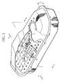
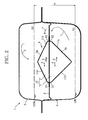
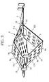
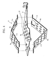
- FIG. 1 illustrates an entire structure of a vehicle fuel tank (hereinafter referred to simply as a fuel tank) mounted below a floor of an automobile, for example, FIG. 2 illustrates a section along A-A line of the fuel tank, and FIGS. 3 and 4 illustrate a structure of a baffle body incorporated in the fuel tank.
- Reference character F in FIG. 1 denotes a front side of the vehicle, while reference character R denotes a rear side of the vehicle.
- Reference numeral 1 in FIG. 1 denotes a tank body of the fuel tank.
- the tank body 1 is formed by joining a lower tank 2 and an upper tank 3.
- the tank body 1 has a box shape in which a vehicle-width direction is long and a longitudinal direction of the vehicle is shorter than the vehicle-width direction, for example.
- a fuel pump module for supplying fuel to an engine (none of them is shown) is installed on one side in the vehicle-width direction of the tank body 1.
- a hole portion 3a on the one side in the vehicle-width direction of the upper tank 3 indicates a hole portion through which the fuel pump module goes in/out.
- a fuel-supply pipe member (not shown) for leading supplied fuel to the tank body 1 is connected to the opposite side, and the fuel is stored inside the tank body 1.
- a flat plate-shaped baffle plate member 5 (corresponding to a baffle plate for support of the present application) is provided so as to cross an inside of the tank body 1 as also illustrated in FIG. 2 .
- This baffle plate member 5 is made of a flat plate-shaped plate in which a large number of through holes 5a are drilled.
- This baffle plate member 5 is arranged so as to vertically cross the space on a middle stage in the tank body 1.
- a through hole 5b through which a fuel-supply pipe member passes is formed in a plate portion on a side opposite to the hole portion 3a of the baffle plate member 5.
- baffle body 6 On a region of the baffle plate member 5 which avoids a portion to become an obstacle such as the fuel-supply pipe member, the fuel pump module and the like, that is, a region from the center to the one side, for example, a baffle body 6 which is an essential part of the present invention is provided.
- the baffle body 6 is formed by a three-dimensional object (structure) forming a chamber space 10 holding the stored fuel without using a wall portion of the tank body 1 as illustrated in FIGS. 1 and 2 .
- the baffle body 6 for example, uses a structure in which a pair of bent baffle plate members 8a and 8b each being bent into a mountain shape are assembled onto upper and lower surfaces of the baffle plate member 5 as illustrated in FIGS. 3 and 4 so as to form the chamber space 10 as a closed section at a point away from the inner surface of the tank body 1.
- baffle plate members 8a and 8b baffle plate members both having mountain shapes and through holes 9a and 9b on the wall surface are used.
- the chamber space 10 uses a structure in which these baffle plate members are attached to upper and lower surface portions of the baffle plate member 5 in an attitude with an axial direction directed to a vehicle-width direction and opening sides facing each other vertically (faced attitude) as illustrated in FIG. 4 .
- a chamber space portion 7 having a triangular cylindrical shape with a vehicle-longitudinal direction becoming a closed space, respectively, is formed in a region surrounded by the baffle plate member 5 and the bent baffle plate members 8a and 8b.
- the chamber space 10 is formed of a space having a diamond-shaped section obtained by combining these two chamber space portions 7 and 7. In this way, the chamber space 10 is formed at the point away from the entire inner surface of the tank body 1.
- This chamber space 10 is supported by using the baffle plate member 5 crossing inside the tank body 1 described above as a supporting member. That is, the chamber space 10 is installed in the tank body 1 with a structure not using the wall portion of the tank body 1 as a side like conventional ones.
- This chamber space 10 is, as illustrated in FIG. 2 , arranged in the tank body 1 so as to occupy a horizontal direction inside the tank body as much as possible.
- the upper bent baffle plate member 8a forming the chamber space 10 in that extends to the vicinity of a full amount position A2 of the fuel tank, while the lower bent baffle plate member 8b extends to the vicinity of a lower limit position A1 of the fuel tank, and the chamber space 10 is arranged so as to occupy the most of a tank region H from the lower limit position A1 at which the fuel can be stored to the full amount position A2 of the fuel tank.
- the fuel can be held by the chamber space 10 in any stored state so that the fuel is made difficult to move in any state.
- the wall portions on the both sides in the vehicle longitudinal direction of the chamber space 10 and the upper side form a structure which can diffuse the fuel bounced back from the inner surface of the tank body 1 using the diamond sectional shape. That is, on the wall portions on the both sides in the vehicle longitudinal direction of the chamber space 10 and the upper side, two inclined surfaces 11a and 11b narrowed to each other as they go toward the inner surface of the tank body 1 and forming a diffusion portion, and a corner portion 12 formed at a portion where tip end portions of the inclined surfaces 11a and 11b intersect each other are formed by using the diamond sectional structure. That is, the structure is configured such that the corner portion 12 cuts off the fuel bounced back from the inner surface of the tank body 1 and the cut-off fuel is diffused by the inclined surfaces 11a and 11b.
- the fuel in the tank body 1 which is to flow upon behavior such as start of the vehicle or acceleration/deceleration during traveling as indicated by arrows a and b in FIG. 2 , for example, is held in the chamber space 10 of the baffle body 6 and thus, it is difficult to move, and flow of the fuel is suppressed.
- the flow energy of the fuel is suppressed by this suppression.
- the chamber space 10 is arranged away from the entire inner surface of the tank body 1, the fuel in the chamber space 10 does not directly collide against the inner wall of the tank body 1. Thus, the flow noise caused by the collision is not directly transmitted to the wall surface of the tank body 1.
- the flow noise leaking from the fuel tank can be suppressed, and the noise generated in the fuel tank can be reduced.
- the chamber space 10 of the baffle body 6 is arranged so as to occupy the most from the lower limit position A1 to the full amount position A2 of the fuel amount, the flow noise leaking from the fuel tank can be suppressed under any fuel stored amount.
- the chamber space 10 can be obtained only by forming a closed section by using the bent baffle plate members 8a and 8b as the wall portions, which is a simple structure.
- the fuel bounced back from the inner surfaces of a side wall and an upper wall of the tank body 1 as indicated by arrows c and d in FIG. 2 has the flow energy suppressed by the behavior that the fuel is cut off by the corner portion 12 and diffused on the inclined surfaces 11a and 11b at start and acceleration/deceleration of the vehicle and the like.
- the flow noise caused by the fuel bounced back from the inner surface of the tank body 1 can be suppressed, and the flow noise of the fuel tank can be effectively reduced.
- the baffle body 6 is supported by the tank body 1 by using the baffle plate member 5 forming the baffle plate for support, alleviation of the flow energy generated by the baffle plate member 5 is added to the alleviation of the flow energy generated by the chamber space 10, and the flow noise is further reduced.
- the present invention is not limited to the above described embodiment but may be variously varied in practice within a range not departing from the gist of the present invention.
- a diamond shape combining triangular cylindrical shape is employed as the shape of the chamber space, but this is not limiting, and other shapes such as a square cylinder, a triangular cylinder or more polygonal cylinder and the like may be employed.
- the chamber space does not have to be cylindrical and the periphery of a space may be fully closed, and the number does not have to be one but may be plural.
- the number of the inclined surfaces which diffuse the fuel while cutting it off does not have to be two but more inclined surfaces may be used for diffusion.
- the fuel tank having a box shape extending uniformly in the vehicle-width direction is cited, but this is not limiting, and the fuel tank having a saddle shape may be similarly cited.
Landscapes
- Engineering & Computer Science (AREA)
- Chemical & Material Sciences (AREA)
- Combustion & Propulsion (AREA)
- Mechanical Engineering (AREA)
- Life Sciences & Earth Sciences (AREA)
- Sustainable Development (AREA)
- Sustainable Energy (AREA)
- Transportation (AREA)
- General Engineering & Computer Science (AREA)
- Cooling, Air Intake And Gas Exhaust, And Fuel Tank Arrangements In Propulsion Units (AREA)
Abstract
Description
- The present invention relates to a vehicle fuel tank and particularly relates to improvement of a structure for suppressing a flow noise of fuel.
- In a fuel tank mounted on an automobile (vehicle), fuel stored therein can easily flow, and the fuel flows in the tank and collides against an inner surface of the fuel tank or the fuel bounced back by the inner surface collides against the stored fuel at start or acceleration/deceleration during traveling, which can easily cause disturbing flow noises.
- In the fuel tank, in order to reduce this flow noise, flow energy of the fuel is to be reduced by using a baffle body. For such reduction of the flow energy, a method of forming a chamber space holding the fuel in the fuel tank so as to make the fuel difficult to move is employed in many cases.
- Conventionally, as such chamber space for making the fuel difficult to move, a structure of forming the chamber space as a closed space in which the inner wall of the tank body of the fuel tank is formed as it is as a wall portion of the chamber space is employed by using a baffle plate and an inner wall of a tank body of the fuel tank as disclosed in FIG. 6 of
Patent Document 1, and the fuel is surrounded by the chamber space so as to make the fuel difficult to move and to suppress the flow energy colliding against the inner wall of the tank body. It is needless to say that the stored fuel can flow in/out of the chamber space. - Patent Document 1: Japanese Patent Laid-Open No.
2007-307918 - However, that structure also has a problem. That is, the wall portion of the tank body constitutes a wall portion of the chamber space. Thus, a noise caused by the fuel moving in the chamber space and the flow noise generated when the fuel collides are directly transmitted to the wall portion of the tank body and leaks out of the tank body and can cause a factor of noises.
- Thus, an object of the present invention is to provide a vehicle fuel tank which suppresses leakage of the flow noise of the fuel in the chamber space of the baffle body to the outside of the fuel tank.
- A vehicle fuel tank described in
claim 1 employs a structure in which a chamber space into/out of which stored fuel can flow is formed at a point away from an inner surface of a tank body for a baffle body in order to achieve the above described object. - In an invention described in
claim 2, the chamber space of the baffle body is configured to occupy the most from a lower limit position to a full amount position of a fuel amount which can be stored in the fuel tank. - In an invention described in
claim 3, the chamber space is configured to form a closed section by using a baffle plate member as a wall portion. - In an invention described in claim 4, the chamber space is configured to be formed having at least two inclined surfaces which are narrowed as they go toward the inner surface of the tank body and a wall portion having a corner portion on a tip end side formed by intersection of the inclined surfaces.
- In an invention described in
claim 5, the baffle body is configured to be supported by the tank body through the baffle plate member for support. - According to the invention in
claim 1, since the chamber space is located away from the inner surface of the tank body, not only that the flow energy colliding against the inner wall of the tank body is suppressed, but also that the flow noise of the fuel in the chamber space of the baffle body can be configured not to be directly transmitted to the tank body. - Thus, the flow noise leaking from the fuel tank is suppressed, and reduction of the noise can be realized.
- According to the invention of
claim 2, the flow noise leaking from the fuel tank can be suppressed in any stored amount of the fuel. - According to the invention in
claim 3, the chamber space can be formed with a simple structure. - According to the invention in claim 4, the fuel bounced back from the inner surface of the tank body due to start and acceleration/deceleration or the like is diffused while being cut off by the corner portion and the inclined surface. Thus, the flow noise caused by the fuel bounced back from the inner surface of the tank body can be suppressed, and the flow noise of the fuel tank can be effectively reduced.
- According to the invention in
claim 5, alleviation of the flow energy by the baffle plate member for support is added to alleviation of the flow energy by the chamber space, and reduction of the flow noise can be further realized. -
-
FIG. 1 is a partially cut-away perspective view of a vehicle fuel tank according to an embodiment of the present invention illustrated together with a baffle body attached to the tank. -
FIG. 2 is a sectional view of the vehicle fuel tank along A-A line inFIG. 1 . -
FIG. 3 is a perspective view illustrating a chamber space structure of the baffle body. -
FIG. 4 is an exploded perspective view of the baffle body. - The present invention will be explained below on the basis of an embodiment illustrated in
FIGS. 1 to 4 . -
FIG. 1 illustrates an entire structure of a vehicle fuel tank (hereinafter referred to simply as a fuel tank) mounted below a floor of an automobile, for example,FIG. 2 illustrates a section along A-A line of the fuel tank, andFIGS. 3 and4 illustrate a structure of a baffle body incorporated in the fuel tank. Reference character F inFIG. 1 denotes a front side of the vehicle, while reference character R denotes a rear side of the vehicle. - A structure of the fuel tank will be explained.
Reference numeral 1 inFIG. 1 denotes a tank body of the fuel tank. Thetank body 1 is formed by joining alower tank 2 and anupper tank 3. Thetank body 1 has a box shape in which a vehicle-width direction is long and a longitudinal direction of the vehicle is shorter than the vehicle-width direction, for example. A fuel pump module for supplying fuel to an engine (none of them is shown) is installed on one side in the vehicle-width direction of thetank body 1. Ahole portion 3a on the one side in the vehicle-width direction of theupper tank 3 indicates a hole portion through which the fuel pump module goes in/out. A fuel-supply pipe member (not shown) for leading supplied fuel to thetank body 1 is connected to the opposite side, and the fuel is stored inside thetank body 1. - On the one side in the
tank body 1 which avoids the fuel pump module, for example, a flat plate-shaped baffle plate member 5 (corresponding to a baffle plate for support of the present application) is provided so as to cross an inside of thetank body 1 as also illustrated inFIG. 2 . Thisbaffle plate member 5 is made of a flat plate-shaped plate in which a large number of throughholes 5a are drilled. Thisbaffle plate member 5 is arranged so as to vertically cross the space on a middle stage in thetank body 1. Moreover, athrough hole 5b through which a fuel-supply pipe member passes is formed in a plate portion on a side opposite to thehole portion 3a of thebaffle plate member 5. - On a region of the
baffle plate member 5 which avoids a portion to become an obstacle such as the fuel-supply pipe member, the fuel pump module and the like, that is, a region from the center to the one side, for example, abaffle body 6 which is an essential part of the present invention is provided. Thebaffle body 6 is formed by a three-dimensional object (structure) forming achamber space 10 holding the stored fuel without using a wall portion of thetank body 1 as illustrated inFIGS. 1 and2 . - Here, the
baffle body 6, for example, uses a structure in which a pair of bentbaffle plate members baffle plate member 5 as illustrated inFIGS. 3 and4 so as to form thechamber space 10 as a closed section at a point away from the inner surface of thetank body 1. - Specifically, for the bent
baffle plate members holes chamber space 10 uses a structure in which these baffle plate members are attached to upper and lower surface portions of thebaffle plate member 5 in an attitude with an axial direction directed to a vehicle-width direction and opening sides facing each other vertically (faced attitude) as illustrated inFIG. 4 . Thus, achamber space portion 7 having a triangular cylindrical shape with a vehicle-longitudinal direction becoming a closed space, respectively, is formed in a region surrounded by thebaffle plate member 5 and the bentbaffle plate members chamber space 10 is formed of a space having a diamond-shaped section obtained by combining these twochamber space portions chamber space 10 is formed at the point away from the entire inner surface of thetank body 1. Thischamber space 10 is supported by using thebaffle plate member 5 crossing inside thetank body 1 described above as a supporting member. That is, thechamber space 10 is installed in thetank body 1 with a structure not using the wall portion of thetank body 1 as a side like conventional ones. - This
chamber space 10 is, as illustrated inFIG. 2 , arranged in thetank body 1 so as to occupy a horizontal direction inside the tank body as much as possible. The upper bentbaffle plate member 8a forming thechamber space 10 in that extends to the vicinity of a full amount position A2 of the fuel tank, while the lower bentbaffle plate member 8b extends to the vicinity of a lower limit position A1 of the fuel tank, and thechamber space 10 is arranged so as to occupy the most of a tank region H from the lower limit position A1 at which the fuel can be stored to the full amount position A2 of the fuel tank. Thus, it is so configured that the fuel can be held by thechamber space 10 in any stored state so that the fuel is made difficult to move in any state. - Moreover, the wall portions on the both sides in the vehicle longitudinal direction of the
chamber space 10 and the upper side form a structure which can diffuse the fuel bounced back from the inner surface of thetank body 1 using the diamond sectional shape. That is, on the wall portions on the both sides in the vehicle longitudinal direction of thechamber space 10 and the upper side, twoinclined surfaces tank body 1 and forming a diffusion portion, and acorner portion 12 formed at a portion where tip end portions of theinclined surfaces corner portion 12 cuts off the fuel bounced back from the inner surface of thetank body 1 and the cut-off fuel is diffused by theinclined surfaces - According to the fuel tank configured as above, the fuel in the
tank body 1 which is to flow upon behavior such as start of the vehicle or acceleration/deceleration during traveling as indicated by arrows a and b inFIG. 2 , for example, is held in thechamber space 10 of thebaffle body 6 and thus, it is difficult to move, and flow of the fuel is suppressed. The flow energy of the fuel is suppressed by this suppression. - At this time, since the
chamber space 10 is arranged away from the entire inner surface of thetank body 1, the fuel in thechamber space 10 does not directly collide against the inner wall of thetank body 1. Thus, the flow noise caused by the collision is not directly transmitted to the wall surface of thetank body 1. - That is, by providing the
chamber space 10 away from the entire inner surface of thetank body 1, not only the flow energy is suppressed but also the flow noise of the fuel in thechamber space 10 is kept from being directly transmitted to the tank body. - Thus, the flow noise leaking from the fuel tank can be suppressed, and the noise generated in the fuel tank can be reduced. Particularly, since the
chamber space 10 of thebaffle body 6 is arranged so as to occupy the most from the lower limit position A1 to the full amount position A2 of the fuel amount, the flow noise leaking from the fuel tank can be suppressed under any fuel stored amount. - Moreover, the
chamber space 10 can be obtained only by forming a closed section by using the bentbaffle plate members - Furthermore, by forming the wall portions of the
chamber space 10, that is, by forming the wall portions on the both sides in the longitudinal direction and the upper side, here, by the wall portion having the twoinclined surfaces tank body 1 and thecorner portion 12 on the tip end side, the fuel bounced back from the inner surfaces of a side wall and an upper wall of thetank body 1 as indicated by arrows c and d inFIG. 2 has the flow energy suppressed by the behavior that the fuel is cut off by thecorner portion 12 and diffused on theinclined surfaces tank body 1 can be suppressed, and the flow noise of the fuel tank can be effectively reduced. - Particularly, if the
baffle body 6 is supported by thetank body 1 by using thebaffle plate member 5 forming the baffle plate for support, alleviation of the flow energy generated by thebaffle plate member 5 is added to the alleviation of the flow energy generated by thechamber space 10, and the flow noise is further reduced. - The present invention is not limited to the above described embodiment but may be variously varied in practice within a range not departing from the gist of the present invention. For example, in the embodiment, a diamond shape combining triangular cylindrical shape is employed as the shape of the chamber space, but this is not limiting, and other shapes such as a square cylinder, a triangular cylinder or more polygonal cylinder and the like may be employed. It is needless to say that the chamber space does not have to be cylindrical and the periphery of a space may be fully closed, and the number does not have to be one but may be plural. In short, it is only necessary to form the chamber space without using the inner surfaces of the tank body. Moreover, the number of the inclined surfaces which diffuse the fuel while cutting it off does not have to be two but more inclined surfaces may be used for diffusion.
- Moreover, in the embodiment, the fuel tank having a box shape extending uniformly in the vehicle-width direction is cited, but this is not limiting, and the fuel tank having a saddle shape may be similarly cited.
-
- 1 tank body
- 5 baffle plate member (baffle plate member for support)
- 6 baffle body
- 7
chamber space portion - 10 chamber space
- 11a, 11b inclined surface
- 12 corner portion
Claims (5)
- A vehicle fuel tank having a tank body mounted on a vehicle and storing fuel and a baffle body disposed in the tank body, wherein
the baffle body has a chamber space in/out of which stored fuel in the tank body can flow; and
the chamber space is formed at a point away from an inner surface of the tank body. - The vehicle fuel tank according to claim 1, wherein
the chamber space of the baffle body occupies the most from a lower limit position to a full amount position of a fuel amount that can be stored in the fuel tank. - The vehicle fuel tank according to claim 1 or 2, wherein
the baffle body has a baffle plate member, and the chamber space is formed by a construction in which a closed section is formed by using the baffle plate member as a wall portion. - The vehicle fuel tank according to any one of claims 1 to 3, wherein
the chamber space is formed having a wall portion including:at least two inclined surfaces narrowed to each other as they go toward the inner surface of the tank body; anda corner portion on a tip end side formed by intersection of the inclined surfaces. - The vehicle fuel tank according to any one of claims 1 to 4, wherein
the baffle body is supported by the tank body through the baffle plate member for support.
Applications Claiming Priority (2)
| Application Number | Priority Date | Filing Date | Title |
|---|---|---|---|
| JP2012089200A JP5843067B2 (en) | 2012-04-10 | 2012-04-10 | Vehicle fuel tank |
| PCT/JP2013/058063 WO2013153929A1 (en) | 2012-04-10 | 2013-03-21 | Vehicle fuel tank |
Publications (3)
| Publication Number | Publication Date |
|---|---|
| EP2837519A1 true EP2837519A1 (en) | 2015-02-18 |
| EP2837519A4 EP2837519A4 (en) | 2015-12-30 |
| EP2837519B1 EP2837519B1 (en) | 2018-07-25 |
Family
ID=49327502
Family Applications (1)
| Application Number | Title | Priority Date | Filing Date |
|---|---|---|---|
| EP13775177.2A Active EP2837519B1 (en) | 2012-04-10 | 2013-03-21 | Vehicle fuel tank |
Country Status (5)
| Country | Link |
|---|---|
| US (1) | US20150069070A1 (en) |
| EP (1) | EP2837519B1 (en) |
| JP (1) | JP5843067B2 (en) |
| CN (1) | CN104428155B (en) |
| WO (1) | WO2013153929A1 (en) |
Cited By (1)
| Publication number | Priority date | Publication date | Assignee | Title |
|---|---|---|---|---|
| GB2539270A (en) * | 2015-06-12 | 2016-12-14 | Jaguar Land Rover Ltd | Control system, vehicle and method |
Families Citing this family (14)
| Publication number | Priority date | Publication date | Assignee | Title |
|---|---|---|---|---|
| RU2016120184A (en) * | 2013-10-25 | 2017-11-27 | Хелджисен Индастриз, Инк. | LIQUID STORAGE TANK CONTAINING A WAVE EXTINGUISHING PARTITION |
| US9493068B2 (en) * | 2014-11-18 | 2016-11-15 | GM Global Technology Operations LLC | Fuel tank baffle |
| CN105015329B (en) * | 2015-08-06 | 2018-03-30 | 中冶京诚(湘潭)矿山装备有限公司 | A kind of quarry tipper, fuel tank and its swash plate |
| US10065751B2 (en) * | 2016-04-05 | 2018-09-04 | Orbital Atk, Inc. | Liquid storage tanks and systems and propulsion systems for space vehicles and related methods |
| JP6315059B1 (en) * | 2016-10-24 | 2018-04-25 | マツダ株式会社 | Vehicle tank structure |
| JP6315060B1 (en) * | 2016-10-24 | 2018-04-25 | マツダ株式会社 | Vehicle tank structure |
| JP6794830B2 (en) * | 2016-12-28 | 2020-12-02 | スズキ株式会社 | Vehicle fuel tank |
| CN110944891B (en) * | 2017-07-13 | 2022-01-04 | 本田技研工业株式会社 | Brake fluid recovery and supply method and brake fluid recovery and supply device |
| JP7253976B2 (en) * | 2019-05-21 | 2023-04-07 | 株式会社丸山製作所 | liquid tank equipment |
| WO2020251001A1 (en) * | 2019-06-12 | 2020-12-17 | 日本製鉄株式会社 | Fuel tank |
| US11396420B2 (en) | 2019-08-09 | 2022-07-26 | Roger Hayes | Tank for transporting liquids |
| WO2022020675A1 (en) * | 2020-07-23 | 2022-01-27 | Capat Llc | Modular fuel tank assembly and method of construction |
| CN114161926A (en) * | 2022-01-13 | 2022-03-11 | 晋爱娇 | Reinforcing device of automobile fuel tank and large and medium fuel vehicle fuel tank |
| US12534292B1 (en) * | 2022-12-23 | 2026-01-27 | Luke Waesche | Tank, tank components, and system for use, transport, processing, and/or storage of liquids therein and methods of use thereof |
Family Cites Families (35)
| Publication number | Priority date | Publication date | Assignee | Title |
|---|---|---|---|---|
| US2533431A (en) * | 1944-11-07 | 1950-12-12 | Chausson Usines Sa | Tank for airplanes and similar applications |
| DE2128535C2 (en) * | 1970-08-06 | 1984-01-05 | Carlo Settimo Milanese Milano Chiti | Fireproof fuel container for land and water vehicles |
| JPS5422807Y2 (en) * | 1977-10-26 | 1979-08-08 | ||
| JPS56172429U (en) * | 1980-05-26 | 1981-12-19 | ||
| CA1152462A (en) * | 1980-07-30 | 1983-08-23 | White (George) & Sons Inc. | Tank-baffle system |
| DE3530228A1 (en) * | 1985-08-23 | 1987-03-05 | Westerwaelder Eisen Gerhard | TRANSPORT TANK WITH SPILL PROTECTION ELEMENTS |
| JPH0623462Y2 (en) * | 1985-12-27 | 1994-06-22 | 日産自動車株式会社 | Liquid noise prevention device for fuel tank |
| JPS6367330U (en) * | 1986-10-23 | 1988-05-06 | ||
| JPH0234443U (en) * | 1988-08-29 | 1990-03-05 | ||
| JP2690173B2 (en) * | 1990-05-31 | 1997-12-10 | キヤノン株式会社 | Image forming device |
| JPH0476526U (en) * | 1990-11-19 | 1992-07-03 | ||
| JPH06144030A (en) * | 1992-11-04 | 1994-05-24 | Horie Kinzoku Kogyo Kk | Fuel tank |
| US6293420B1 (en) * | 1997-07-25 | 2001-09-25 | Kautex Textron Gmbh & Co., Kg. | Fuel tank |
| US6431388B1 (en) * | 1998-05-06 | 2002-08-13 | W. James Spickelmire | Liquid stabilizing baffle |
| US5960981A (en) * | 1998-06-15 | 1999-10-05 | Emergency One, Inc. | Water tank baffle |
| US6338420B1 (en) * | 1999-06-08 | 2002-01-15 | Delphi Technologies, Inc. | Motor vehicle fuel tank and method |
| US6220287B1 (en) * | 2000-02-03 | 2001-04-24 | The Boeing Company | Baffle for suppressing slosh in a tank and a tank for incorporating same |
| DE10008985A1 (en) * | 2000-02-25 | 2001-08-30 | Linde Ag | Storage tank |
| GB2374056B (en) * | 2001-04-06 | 2004-08-18 | Darchem Engineering Ltd | Impact-resistant fuel tank device |
| US7735507B2 (en) * | 2001-06-01 | 2010-06-15 | Hagenbuch Leroy G | Baffled tank for a vehicle |
| US20030015537A1 (en) * | 2001-07-19 | 2003-01-23 | Konja Namir A. | Vehicle fuel tank with fuel wave baffle |
| US6901941B2 (en) * | 2002-07-10 | 2005-06-07 | Air Products And Chemicals, Inc. | Vessel with optimized purge gas flow and method using same |
| US6568556B1 (en) * | 2002-09-23 | 2003-05-27 | Visteon Global Technologies, Inc. | Fuel tank baffle |
| US7028382B2 (en) * | 2003-10-22 | 2006-04-18 | Fisher Keith B | Methods of tank construction |
| KR100581795B1 (en) * | 2004-08-13 | 2006-05-23 | 현대자동차주식회사 | Mounting Structure of Integral Baffle Plate of Fuel Tank |
| US7445082B2 (en) * | 2005-04-21 | 2008-11-04 | Nifco Inc. | Noise suppressing device and installation structure of same |
| JP4826335B2 (en) | 2006-05-16 | 2011-11-30 | 三菱自動車工業株式会社 | Vehicle fuel tank |
| US8235241B2 (en) * | 2007-09-21 | 2012-08-07 | Honda Motor Co., Ltd. | Floating absorber assembly for reduced fuel slosh noise |
| KR100962193B1 (en) * | 2007-11-28 | 2010-06-10 | 현대자동차주식회사 | Baffle Unit |
| KR101427910B1 (en) * | 2008-11-07 | 2014-08-11 | 현대자동차 주식회사 | Baffle unit for vehicle fuel tank |
| DE102008060121A1 (en) * | 2008-12-03 | 2010-06-17 | Continental Automotive Gmbh | Liquid container for a motor vehicle |
| EP2248696B1 (en) * | 2009-05-04 | 2015-04-08 | Ford Global Technologies, LLC | Use of a fuel tank with compensation conduit |
| US20110017748A1 (en) * | 2009-07-24 | 2011-01-27 | Ford Global Technologies, Llc | Liquid fuel storage tank for automotive vehicle |
| US10029848B2 (en) * | 2010-05-05 | 2018-07-24 | Victor Yaremenko | Flexible liquid transport tank with surge dampening baffles |
| US20110303677A1 (en) * | 2010-06-14 | 2011-12-15 | James Heppner | Oil pan barrier |
-
2012
- 2012-04-10 JP JP2012089200A patent/JP5843067B2/en active Active
-
2013
- 2013-03-21 CN CN201380026073.1A patent/CN104428155B/en active Active
- 2013-03-21 EP EP13775177.2A patent/EP2837519B1/en active Active
- 2013-03-21 WO PCT/JP2013/058063 patent/WO2013153929A1/en not_active Ceased
- 2013-03-21 US US14/391,616 patent/US20150069070A1/en not_active Abandoned
Cited By (2)
| Publication number | Priority date | Publication date | Assignee | Title |
|---|---|---|---|---|
| GB2539270A (en) * | 2015-06-12 | 2016-12-14 | Jaguar Land Rover Ltd | Control system, vehicle and method |
| GB2539270B (en) * | 2015-06-12 | 2019-01-23 | Jaguar Land Rover Ltd | Control system, vehicle and method |
Also Published As
| Publication number | Publication date |
|---|---|
| WO2013153929A1 (en) | 2013-10-17 |
| US20150069070A1 (en) | 2015-03-12 |
| EP2837519A4 (en) | 2015-12-30 |
| CN104428155A (en) | 2015-03-18 |
| EP2837519B1 (en) | 2018-07-25 |
| CN104428155B (en) | 2017-08-15 |
| JP2013216225A (en) | 2013-10-24 |
| JP5843067B2 (en) | 2016-01-13 |
Similar Documents
| Publication | Publication Date | Title |
|---|---|---|
| US20150069070A1 (en) | Vehicle fuel tank | |
| US8801059B2 (en) | Impact absorbing device for vehicle | |
| JP5790714B2 (en) | Vehicle lower structure | |
| CN102092423B (en) | Partition structure and installation structure for installation part | |
| US20160137058A1 (en) | Fuel tank baffle | |
| CN105339242A (en) | Subframe for vehicle | |
| US9242677B2 (en) | Shock absorber housing for vehicle | |
| JP2018118647A (en) | Front part structure of vehicle | |
| US20250178673A1 (en) | Vehicle frame structure | |
| US20160052449A1 (en) | Sound output device for vehicle | |
| JP2018043673A (en) | Fitting structure of tow hook | |
| JP2018199431A (en) | Vehicle body front part structure | |
| CN204688213U (en) | A kind of engine front suspension transverse member assembly | |
| US10435080B2 (en) | Vehicle lower structure | |
| CN203228636U (en) | Fuel box | |
| JP2009255857A (en) | Suspension structure of vehicle | |
| JP2009078648A (en) | Fuel vapor outflow device | |
| KR101356343B1 (en) | Separating element with ventilation ducts | |
| US10040494B2 (en) | Aerodynamic floor pan for a vehicle | |
| JP6315059B1 (en) | Vehicle tank structure | |
| EP2410135B1 (en) | Exhaust plenum flow splitter | |
| KR20070043430A (en) | Car fuel tank | |
| JP2021011164A (en) | undercover | |
| CN102490789A (en) | Car front longitudinal beam structure capable of improving collision performance | |
| JP2009185743A (en) | Intake duct for vehicle |
Legal Events
| Date | Code | Title | Description |
|---|---|---|---|
| PUAI | Public reference made under article 153(3) epc to a published international application that has entered the european phase |
Free format text: ORIGINAL CODE: 0009012 |
|
| 17P | Request for examination filed |
Effective date: 20141017 |
|
| AK | Designated contracting states |
Kind code of ref document: A1 Designated state(s): AL AT BE BG CH CY CZ DE DK EE ES FI FR GB GR HR HU IE IS IT LI LT LU LV MC MK MT NL NO PL PT RO RS SE SI SK SM TR |
|
| AX | Request for extension of the european patent |
Extension state: BA ME |
|
| DAX | Request for extension of the european patent (deleted) | ||
| RA4 | Supplementary search report drawn up and despatched (corrected) |
Effective date: 20151201 |
|
| RIC1 | Information provided on ipc code assigned before grant |
Ipc: F02M 37/00 20060101ALI20151125BHEP Ipc: B60K 15/077 20060101AFI20151125BHEP |
|
| STAA | Information on the status of an ep patent application or granted ep patent |
Free format text: STATUS: EXAMINATION IS IN PROGRESS |
|
| 17Q | First examination report despatched |
Effective date: 20170518 |
|
| GRAP | Despatch of communication of intention to grant a patent |
Free format text: ORIGINAL CODE: EPIDOSNIGR1 |
|
| STAA | Information on the status of an ep patent application or granted ep patent |
Free format text: STATUS: GRANT OF PATENT IS INTENDED |
|
| INTG | Intention to grant announced |
Effective date: 20180207 |
|
| GRAS | Grant fee paid |
Free format text: ORIGINAL CODE: EPIDOSNIGR3 |
|
| GRAA | (expected) grant |
Free format text: ORIGINAL CODE: 0009210 |
|
| STAA | Information on the status of an ep patent application or granted ep patent |
Free format text: STATUS: THE PATENT HAS BEEN GRANTED |
|
| AK | Designated contracting states |
Kind code of ref document: B1 Designated state(s): AL AT BE BG CH CY CZ DE DK EE ES FI FR GB GR HR HU IE IS IT LI LT LU LV MC MK MT NL NO PL PT RO RS SE SI SK SM TR |
|
| REG | Reference to a national code |
Ref country code: GB Ref legal event code: FG4D |
|
| REG | Reference to a national code |
Ref country code: CH Ref legal event code: EP |
|
| REG | Reference to a national code |
Ref country code: AT Ref legal event code: REF Ref document number: 1021367 Country of ref document: AT Kind code of ref document: T Effective date: 20180815 |
|
| REG | Reference to a national code |
Ref country code: IE Ref legal event code: FG4D |
|
| REG | Reference to a national code |
Ref country code: DE Ref legal event code: R096 Ref document number: 602013040862 Country of ref document: DE |
|
| REG | Reference to a national code |
Ref country code: NL Ref legal event code: MP Effective date: 20180725 |
|
| REG | Reference to a national code |
Ref country code: LT Ref legal event code: MG4D |
|
| PG25 | Lapsed in a contracting state [announced via postgrant information from national office to epo] |
Ref country code: NL Free format text: LAPSE BECAUSE OF FAILURE TO SUBMIT A TRANSLATION OF THE DESCRIPTION OR TO PAY THE FEE WITHIN THE PRESCRIBED TIME-LIMIT Effective date: 20180725 |
|
| REG | Reference to a national code |
Ref country code: AT Ref legal event code: MK05 Ref document number: 1021367 Country of ref document: AT Kind code of ref document: T Effective date: 20180725 |
|
| PG25 | Lapsed in a contracting state [announced via postgrant information from national office to epo] |
Ref country code: LT Free format text: LAPSE BECAUSE OF FAILURE TO SUBMIT A TRANSLATION OF THE DESCRIPTION OR TO PAY THE FEE WITHIN THE PRESCRIBED TIME-LIMIT Effective date: 20180725 Ref country code: RS Free format text: LAPSE BECAUSE OF FAILURE TO SUBMIT A TRANSLATION OF THE DESCRIPTION OR TO PAY THE FEE WITHIN THE PRESCRIBED TIME-LIMIT Effective date: 20180725 Ref country code: IS Free format text: LAPSE BECAUSE OF FAILURE TO SUBMIT A TRANSLATION OF THE DESCRIPTION OR TO PAY THE FEE WITHIN THE PRESCRIBED TIME-LIMIT Effective date: 20181125 Ref country code: PL Free format text: LAPSE BECAUSE OF FAILURE TO SUBMIT A TRANSLATION OF THE DESCRIPTION OR TO PAY THE FEE WITHIN THE PRESCRIBED TIME-LIMIT Effective date: 20180725 Ref country code: BG Free format text: LAPSE BECAUSE OF FAILURE TO SUBMIT A TRANSLATION OF THE DESCRIPTION OR TO PAY THE FEE WITHIN THE PRESCRIBED TIME-LIMIT Effective date: 20181025 Ref country code: AT Free format text: LAPSE BECAUSE OF FAILURE TO SUBMIT A TRANSLATION OF THE DESCRIPTION OR TO PAY THE FEE WITHIN THE PRESCRIBED TIME-LIMIT Effective date: 20180725 Ref country code: NO Free format text: LAPSE BECAUSE OF FAILURE TO SUBMIT A TRANSLATION OF THE DESCRIPTION OR TO PAY THE FEE WITHIN THE PRESCRIBED TIME-LIMIT Effective date: 20181025 Ref country code: SE Free format text: LAPSE BECAUSE OF FAILURE TO SUBMIT A TRANSLATION OF THE DESCRIPTION OR TO PAY THE FEE WITHIN THE PRESCRIBED TIME-LIMIT Effective date: 20180725 Ref country code: GR Free format text: LAPSE BECAUSE OF FAILURE TO SUBMIT A TRANSLATION OF THE DESCRIPTION OR TO PAY THE FEE WITHIN THE PRESCRIBED TIME-LIMIT Effective date: 20181026 Ref country code: FI Free format text: LAPSE BECAUSE OF FAILURE TO SUBMIT A TRANSLATION OF THE DESCRIPTION OR TO PAY THE FEE WITHIN THE PRESCRIBED TIME-LIMIT Effective date: 20180725 |
|
| PG25 | Lapsed in a contracting state [announced via postgrant information from national office to epo] |
Ref country code: AL Free format text: LAPSE BECAUSE OF FAILURE TO SUBMIT A TRANSLATION OF THE DESCRIPTION OR TO PAY THE FEE WITHIN THE PRESCRIBED TIME-LIMIT Effective date: 20180725 Ref country code: LV Free format text: LAPSE BECAUSE OF FAILURE TO SUBMIT A TRANSLATION OF THE DESCRIPTION OR TO PAY THE FEE WITHIN THE PRESCRIBED TIME-LIMIT Effective date: 20180725 Ref country code: HR Free format text: LAPSE BECAUSE OF FAILURE TO SUBMIT A TRANSLATION OF THE DESCRIPTION OR TO PAY THE FEE WITHIN THE PRESCRIBED TIME-LIMIT Effective date: 20180725 |
|
| REG | Reference to a national code |
Ref country code: DE Ref legal event code: R097 Ref document number: 602013040862 Country of ref document: DE |
|
| PG25 | Lapsed in a contracting state [announced via postgrant information from national office to epo] |
Ref country code: IT Free format text: LAPSE BECAUSE OF FAILURE TO SUBMIT A TRANSLATION OF THE DESCRIPTION OR TO PAY THE FEE WITHIN THE PRESCRIBED TIME-LIMIT Effective date: 20180725 Ref country code: EE Free format text: LAPSE BECAUSE OF FAILURE TO SUBMIT A TRANSLATION OF THE DESCRIPTION OR TO PAY THE FEE WITHIN THE PRESCRIBED TIME-LIMIT Effective date: 20180725 Ref country code: ES Free format text: LAPSE BECAUSE OF FAILURE TO SUBMIT A TRANSLATION OF THE DESCRIPTION OR TO PAY THE FEE WITHIN THE PRESCRIBED TIME-LIMIT Effective date: 20180725 Ref country code: RO Free format text: LAPSE BECAUSE OF FAILURE TO SUBMIT A TRANSLATION OF THE DESCRIPTION OR TO PAY THE FEE WITHIN THE PRESCRIBED TIME-LIMIT Effective date: 20180725 Ref country code: CZ Free format text: LAPSE BECAUSE OF FAILURE TO SUBMIT A TRANSLATION OF THE DESCRIPTION OR TO PAY THE FEE WITHIN THE PRESCRIBED TIME-LIMIT Effective date: 20180725 |
|
| PG25 | Lapsed in a contracting state [announced via postgrant information from national office to epo] |
Ref country code: SK Free format text: LAPSE BECAUSE OF FAILURE TO SUBMIT A TRANSLATION OF THE DESCRIPTION OR TO PAY THE FEE WITHIN THE PRESCRIBED TIME-LIMIT Effective date: 20180725 Ref country code: SM Free format text: LAPSE BECAUSE OF FAILURE TO SUBMIT A TRANSLATION OF THE DESCRIPTION OR TO PAY THE FEE WITHIN THE PRESCRIBED TIME-LIMIT Effective date: 20180725 Ref country code: DK Free format text: LAPSE BECAUSE OF FAILURE TO SUBMIT A TRANSLATION OF THE DESCRIPTION OR TO PAY THE FEE WITHIN THE PRESCRIBED TIME-LIMIT Effective date: 20180725 |
|
| PLBE | No opposition filed within time limit |
Free format text: ORIGINAL CODE: 0009261 |
|
| STAA | Information on the status of an ep patent application or granted ep patent |
Free format text: STATUS: NO OPPOSITION FILED WITHIN TIME LIMIT |
|
| 26N | No opposition filed |
Effective date: 20190426 |
|
| RAP2 | Party data changed (patent owner data changed or rights of a patent transferred) |
Owner name: MITSUBISHI JIDOSHA KOGYO KABUSHIKI KAISHA Owner name: MITSUBISHI JIDOSHA ENGINEERING KABUSHIKI KAISHA |
|
| PG25 | Lapsed in a contracting state [announced via postgrant information from national office to epo] |
Ref country code: SI Free format text: LAPSE BECAUSE OF FAILURE TO SUBMIT A TRANSLATION OF THE DESCRIPTION OR TO PAY THE FEE WITHIN THE PRESCRIBED TIME-LIMIT Effective date: 20180725 |
|
| PG25 | Lapsed in a contracting state [announced via postgrant information from national office to epo] |
Ref country code: MC Free format text: LAPSE BECAUSE OF FAILURE TO SUBMIT A TRANSLATION OF THE DESCRIPTION OR TO PAY THE FEE WITHIN THE PRESCRIBED TIME-LIMIT Effective date: 20180725 |
|
| REG | Reference to a national code |
Ref country code: CH Ref legal event code: PL |
|
| GBPC | Gb: european patent ceased through non-payment of renewal fee |
Effective date: 20190321 |
|
| PG25 | Lapsed in a contracting state [announced via postgrant information from national office to epo] |
Ref country code: LU Free format text: LAPSE BECAUSE OF NON-PAYMENT OF DUE FEES Effective date: 20190321 |
|
| REG | Reference to a national code |
Ref country code: BE Ref legal event code: MM Effective date: 20190331 |
|
| PG25 | Lapsed in a contracting state [announced via postgrant information from national office to epo] |
Ref country code: CH Free format text: LAPSE BECAUSE OF NON-PAYMENT OF DUE FEES Effective date: 20190331 Ref country code: LI Free format text: LAPSE BECAUSE OF NON-PAYMENT OF DUE FEES Effective date: 20190331 Ref country code: IE Free format text: LAPSE BECAUSE OF NON-PAYMENT OF DUE FEES Effective date: 20190321 Ref country code: GB Free format text: LAPSE BECAUSE OF NON-PAYMENT OF DUE FEES Effective date: 20190321 |
|
| PG25 | Lapsed in a contracting state [announced via postgrant information from national office to epo] |
Ref country code: BE Free format text: LAPSE BECAUSE OF NON-PAYMENT OF DUE FEES Effective date: 20190331 |
|
| PG25 | Lapsed in a contracting state [announced via postgrant information from national office to epo] |
Ref country code: TR Free format text: LAPSE BECAUSE OF FAILURE TO SUBMIT A TRANSLATION OF THE DESCRIPTION OR TO PAY THE FEE WITHIN THE PRESCRIBED TIME-LIMIT Effective date: 20180725 |
|
| PG25 | Lapsed in a contracting state [announced via postgrant information from national office to epo] |
Ref country code: MT Free format text: LAPSE BECAUSE OF NON-PAYMENT OF DUE FEES Effective date: 20190321 Ref country code: PT Free format text: LAPSE BECAUSE OF FAILURE TO SUBMIT A TRANSLATION OF THE DESCRIPTION OR TO PAY THE FEE WITHIN THE PRESCRIBED TIME-LIMIT Effective date: 20181125 |
|
| PG25 | Lapsed in a contracting state [announced via postgrant information from national office to epo] |
Ref country code: CY Free format text: LAPSE BECAUSE OF FAILURE TO SUBMIT A TRANSLATION OF THE DESCRIPTION OR TO PAY THE FEE WITHIN THE PRESCRIBED TIME-LIMIT Effective date: 20180725 |
|
| PG25 | Lapsed in a contracting state [announced via postgrant information from national office to epo] |
Ref country code: HU Free format text: LAPSE BECAUSE OF FAILURE TO SUBMIT A TRANSLATION OF THE DESCRIPTION OR TO PAY THE FEE WITHIN THE PRESCRIBED TIME-LIMIT; INVALID AB INITIO Effective date: 20130321 |
|
| PG25 | Lapsed in a contracting state [announced via postgrant information from national office to epo] |
Ref country code: MK Free format text: LAPSE BECAUSE OF FAILURE TO SUBMIT A TRANSLATION OF THE DESCRIPTION OR TO PAY THE FEE WITHIN THE PRESCRIBED TIME-LIMIT Effective date: 20180725 |
|
| PGFP | Annual fee paid to national office [announced via postgrant information from national office to epo] |
Ref country code: DE Payment date: 20260128 Year of fee payment: 14 |
|
| PGFP | Annual fee paid to national office [announced via postgrant information from national office to epo] |
Ref country code: FR Payment date: 20260209 Year of fee payment: 14 |