EP2837429A1 - Dipping bath - Google Patents
Dipping bath Download PDFInfo
- Publication number
- EP2837429A1 EP2837429A1 EP13813651.0A EP13813651A EP2837429A1 EP 2837429 A1 EP2837429 A1 EP 2837429A1 EP 13813651 A EP13813651 A EP 13813651A EP 2837429 A1 EP2837429 A1 EP 2837429A1
- Authority
- EP
- European Patent Office
- Prior art keywords
- dipping bath
- slurry
- inlet
- bath according
- present disclosure
- Prior art date
- Legal status (The legal status is an assumption and is not a legal conclusion. Google has not performed a legal analysis and makes no representation as to the accuracy of the status listed.)
- Granted
Links
Images





Classifications
-
- B—PERFORMING OPERATIONS; TRANSPORTING
- B05—SPRAYING OR ATOMISING IN GENERAL; APPLYING FLUENT MATERIALS TO SURFACES, IN GENERAL
- B05C—APPARATUS FOR APPLYING FLUENT MATERIALS TO SURFACES, IN GENERAL
- B05C3/00—Apparatus in which the work is brought into contact with a bulk quantity of liquid or other fluent material
- B05C3/02—Apparatus in which the work is brought into contact with a bulk quantity of liquid or other fluent material the work being immersed in the liquid or other fluent material
-
- B—PERFORMING OPERATIONS; TRANSPORTING
- B05—SPRAYING OR ATOMISING IN GENERAL; APPLYING FLUENT MATERIALS TO SURFACES, IN GENERAL
- B05C—APPARATUS FOR APPLYING FLUENT MATERIALS TO SURFACES, IN GENERAL
- B05C11/00—Component parts, details or accessories not specifically provided for in groups B05C1/00 - B05C9/00
-
- B—PERFORMING OPERATIONS; TRANSPORTING
- B05—SPRAYING OR ATOMISING IN GENERAL; APPLYING FLUENT MATERIALS TO SURFACES, IN GENERAL
- B05C—APPARATUS FOR APPLYING FLUENT MATERIALS TO SURFACES, IN GENERAL
- B05C3/00—Apparatus in which the work is brought into contact with a bulk quantity of liquid or other fluent material
- B05C3/02—Apparatus in which the work is brought into contact with a bulk quantity of liquid or other fluent material the work being immersed in the liquid or other fluent material
- B05C3/12—Apparatus in which the work is brought into contact with a bulk quantity of liquid or other fluent material the work being immersed in the liquid or other fluent material for treating work of indefinite length
- B05C3/132—Apparatus in which the work is brought into contact with a bulk quantity of liquid or other fluent material the work being immersed in the liquid or other fluent material for treating work of indefinite length supported on conveying means
-
- H—ELECTRICITY
- H01—ELECTRIC ELEMENTS
- H01M—PROCESSES OR MEANS, e.g. BATTERIES, FOR THE DIRECT CONVERSION OF CHEMICAL ENERGY INTO ELECTRICAL ENERGY
- H01M50/00—Constructional details or processes of manufacture of the non-active parts of electrochemical cells other than fuel cells, e.g. hybrid cells
- H01M50/40—Separators; Membranes; Diaphragms; Spacing elements inside cells
- H01M50/403—Manufacturing processes of separators, membranes or diaphragms
-
- Y—GENERAL TAGGING OF NEW TECHNOLOGICAL DEVELOPMENTS; GENERAL TAGGING OF CROSS-SECTIONAL TECHNOLOGIES SPANNING OVER SEVERAL SECTIONS OF THE IPC; TECHNICAL SUBJECTS COVERED BY FORMER USPC CROSS-REFERENCE ART COLLECTIONS [XRACs] AND DIGESTS
- Y02—TECHNOLOGIES OR APPLICATIONS FOR MITIGATION OR ADAPTATION AGAINST CLIMATE CHANGE
- Y02E—REDUCTION OF GREENHOUSE GAS [GHG] EMISSIONS, RELATED TO ENERGY GENERATION, TRANSMISSION OR DISTRIBUTION
- Y02E60/00—Enabling technologies; Technologies with a potential or indirect contribution to GHG emissions mitigation
- Y02E60/10—Energy storage using batteries
-
- Y—GENERAL TAGGING OF NEW TECHNOLOGICAL DEVELOPMENTS; GENERAL TAGGING OF CROSS-SECTIONAL TECHNOLOGIES SPANNING OVER SEVERAL SECTIONS OF THE IPC; TECHNICAL SUBJECTS COVERED BY FORMER USPC CROSS-REFERENCE ART COLLECTIONS [XRACs] AND DIGESTS
- Y02—TECHNOLOGIES OR APPLICATIONS FOR MITIGATION OR ADAPTATION AGAINST CLIMATE CHANGE
- Y02P—CLIMATE CHANGE MITIGATION TECHNOLOGIES IN THE PRODUCTION OR PROCESSING OF GOODS
- Y02P70/00—Climate change mitigation technologies in the production process for final industrial or consumer products
- Y02P70/50—Manufacturing or production processes characterised by the final manufactured product
Definitions
- the present disclosure relates to a dipping bath, and more particularly, to a dipping bath having a structure of allowing a uniform distribution of a slurry therein and increasing a flow rate of the slurry at a bottom surface thereof.
- dip coating is one of the methods of applying a solid coating to a web.
- Dip coating refers to a method that coats a slurry (coating solution) to a web by passing the web through the slurry held in a dipping bath, with the web traveling along a guide roll placed in the dipping bath.
- the slurry coated to the web goes through a drying oven installed outside of the bath, drying a solvent included in the slurry and therefore leaving only solids and an adhesive coated to the web.
- a slurry includes about 80% of a solvent and the remaining 20% of solids and an adhesive, and due to the solids having a higher density than the solvent, a precipitation phenomena in solids may occur at a bottom surface of a bath during a reaction.
- a slurry flows into a bath 1 through an inlet 2 connected to a side surface of the bath, circulates through the bath, and flows out to a circulation tank through an outlet 3 connected to a bottom surface.
- this bath structure has an inherent drawback of reducing in a flow rate of the slurry in an area near the bottom surface, it is difficult to overcome the precipitation phenomena in solids occurring at the bottom surface.
- a coating process must be stopped and an operation of removing the precipitation must be performed, causing a reduction in productivity and a failure to achieve a desired coating property due to the solids being thrown away.
- the present disclosure is designed to solve the problems of the related art, and therefore, the present disclosure is directed to providing a dipping bath that may allow a uniform distribution of a circulating slurry and increase a flow rate of the slurry at a bottom surface.
- a dipping bath includes a body to hold a slurry for dip coating, an inlet installed to flow the slurry from an outside of the body to an inside, and an outlet installed to discharge the slurry from the inside of the body to the outside, and one end of the inlet placed inside the body may be disposed facing a side surface of the body at a distance and may be tilted to a predetermined angle in a direction toward a bottom surface of the body.
- the inlet may penetrate the body.
- the inlet may be connected to the side surface of the body.
- the inlet may be connected to an upper part on the side surface.
- the inlet may be provided plurally, and among the plurality of inlets, at least any one pair may be installed such that one end of each of the inlets faces opposite directions.
- the inlet may be inserted into the body through an open top of the body.
- the outlet may be connected to the side surface of the body.
- the outlet may be connected to a lowest part on the side surface.
- the outlet may be connected to the bottom surface of the body.
- the bottom surface may be slanted down from both sides to a center.
- the outlet may be connected to a lowest location on the bottom surface.
- At least a part on the side surface of the body may be inclined such that an inner space becomes narrow in a direction from top to bottom.
- the inlet may be installed rotatably to enable adjustment of the tilting angle.
- adjustment of an incidence angle of a slurry flowing into a bath through an inlet may increase a flow rate of the slurry toward a bottom surface, as well as allowing a uniform distribution of solids contained in the slurry circulating through the bath.
- an amount of solids settling at a bottom surface of a bath may be minimized by designing the bath to have an inclined bottom surface.
- a flow rate of a slurry at a bottom surface of a bath may be increased by designing the bath to have an incline over at least a part on a side surface of the bath with regard to the bottom surface to minimize an area of the bottom surface.
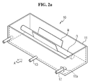
- a dipping bath 10 according to an exemplary embodiment of the present disclosure is described with reference to FIGS. 2a and 2b .
- FIG. 2a is a perspective view illustrating the dipping bath 10 according to an exemplary embodiment of the present disclosure
- FIG. 2b is a view illustrating the dipping bath 10 of FIG. 2a when viewed from a direction A.
- the dipping bath 10 includes a body 11, an inlet 12, and an outlet 13.
- the body 11 corresponds to a container that holds a slurry used for dip coating, and may have a generally rectangular parallelepiped shape with an open top.
- the present disclosure does not limit the shape of the body 11, and it is obvious that any shape of a container having an open top, side surfaces, and a bottom surface falls within the scope of the present disclosure.
- a guide roll R is installed within the body 11, and dip coating is performed by dipping a web W used to manufacture an electrode plate or a separator in a slurry while moving the web W along the guide roll R.
- the inlet 12 corresponds to a passage that enables the slurry to flow from the outside the body 11 to the inside, and may be installed such that one end 12a is put inside through the body 11.
- the inlet 12 may be connected to an upper part on the side surface of the body 11 to allow good circulation of the slurry in the body 11.
- the upper part on the side surface of the body 11 represents an area above the middle by which a height of the side surface is divided into halves.
- the end 12a of the inlet 12 placed inside the body 11 is disposed facing one side surface of the body 11 at a predetermined distance away, and is tilted to a predetermined angle ⁇ in a direction toward the bottom surface of the body 11.
- the slurry flowing into the body 11, through the inlet 12 moves down along the side surface of the body 11 and flows from the edge of the bottom surface to the center.
- This flow path of the slurry may minimize a reduction in flow rate at the bottom surface of the body 11, thereby minimizing precipitation phenomena in which solids contained in the slurry settles at the bottom surface.
- the inlet 12 may be installed rotatably in a direction of an arrow (see FIG. 2a ) to enable adjustment of the tilting angle ⁇ based on the installation location.
- At least one pair of inlets 12 among the plurality of inlets 12 may be installed such that one end 12a of each of the inlets 12 faces opposite directions to achieve good circulation of the whole slurry.
- the drawing shows that the inlet 12 penetrates only the side surface disposed in the direction A among the side surfaces of the body 11, a location in which the inlet 12 is inserted into the body 11 is not limited thereby. That is, it is obvious that the inlet 12 may be inserted into the body 11 through the open top as well as the side surfaces disposed in other directions than the direction A.
- the drawing shows that the inlet 12 is only installed at each opposite side of the body 11, the number of the inlets 12 is not limited thereby. That is, it is obvious that one inlet 12 or at least three inlets 12 may be installed in consideration of a size of the dipping bath 10 and the like.
- the outlet 13 corresponds to a passage connected to the body 11 to discharge the slurry from the inside of the body 11 to the outside.
- the outlet 13 may be connected to a lowest part on the side surface of the body 11 or the bottom surface to allow good discharge of the slurry. In this case, the slurry may be smoothly discharged through the outlet 13 by pressure due to its own weight of the slurry held in the body 11.
- the drawing shows a case in which only one outlet 13 is provided, the number of the outlets 13 is not limited thereby. That is, it is obvious that at least two outlets 13 may be installed in consideration of a size of the dipping bath 10, the number of the inlets 12, and the like.
- the dipping bath 10 may minimize a phenomena in which the flow rate of the slurry reduces at the bottom surface, thereby minimizing a precipitation phenomena in which solids contained in the slurry settle at the bottom surface, since the dipping bath 10 has a structure of enabling the slurry flowing in the body 11 to flow toward the bottom surface after bumping against the side surface.
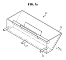
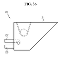
- a dipping bath 20 according to another exemplary embodiment of the present disclosure is described with reference to FIGS. 3a and 3b .
- FIG. 3a is a perspective view illustrating the dipping bath 20 according to another exemplary embodiment of the present disclosure
- FIG. 3b is a view illustrating the dipping bath 20 of FIG. 3a when viewed from a direction B.
- the dipping bath 20 includes a body 21, an inlet 22, and an outlet 23.
- the dipping bath 20 is similar to the dipping bath 10 according to the previous embodiment except in the shape of a side surface of the body 21 and an area of a bottom surface. Accordingly, in the description of the dipping bath 20, an overlapping description is omitted herein, and the description is provided based on the shape of the side surface of the body 21 and the area of the bottom surface.
- At least a part on the side surface of the body 21 is inclined such that an inner space becomes narrow from top to bottom. That is, the dipping bath 20 has such a shape that an area of the bottom surface is smaller than an area of the open top.
- a flow rate of a slurry becomes faster as the slurry gets closer to the bottom surface of the body 21, and thereby a precipitation phenomena in which solids contained in the slurry settle at the bottom surface may be minimized.
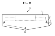
- a dipping bath 20 according to still another exemplary embodiment of the present disclosure is described with reference to FIGS. 4a and 4b .
- FIG. 4a is a perspective view illustrating the dipping bath 30 according to still another exemplary embodiment of the present disclosure
- FIG. 4b is a view illustrating the dipping bath 30 of FIG. 4a when viewed from a direction A.
- the dipping bath 30 includes a body 31, an inlet 32, and an outlet 33.
- the dipping bath 30 is similar to the dipping baths 10 and 20 according to the previous embodiments except in the shape of a bottom surface of the body 31 and an installation location of the outlet 33. Accordingly, in the description of the dipping bath 30, an overlapping description is omitted herein, and the description is provided based on the shape of the bottom surface of the body 31 and the installation location of the outlet 33.
- the bottom surface of the body 31 is inclined such that the body 31 is deeper toward the center. This shape of the bottom surface may minimize a phenomena in which a flow rate of the slurry reduces at the bottom surface, thereby not only minimizing a precipitation phenomena in which solids contained in the slurry settle at the bottom surface but also preventing the precipitation from residing at the bottom surface as well.
- the outlet 33 may be connected to a lowest location on the bottom surface, that is, a location at which inclined planes intersect. In this case, the outlet 33 may effectively discharge the slurry flowing down along the inclined plane to the outside of the body 31.
- the dipping bath 30 may prevent a phenomena in which the flow rate of the slurry reduces at the bottom surface more effectively, thereby reducing a precipitation phenomena in which solids contained in the slurry settle at the bottom surface more effectively.
- a flow rate distribution of the slurry appearing in each of the dipping bath 30 according to the present disclosure and the conventional dipping bath 1 may be compared.
- FIG. 5 is a graph illustrating a comparison of a flow rate distribution of a slurry appearing in the vicinity of the bottom surface of the dipping bath according to the present disclosure and a flow rate distribution of a slurry appearing in the vicinity of the bottom surface of the conventional dipping bath.
- a horizontal axis on the graph of FIG. 5 represents a distance (mm) from an outlet installed in a dipping bath, that is, when FIG. 4b is taken for instance, a movement distance from the outlet 33 to the side surface of the dipping bath along a direction of an arrow, and a longitudinal axis represents a flow rate (m/s) at a corresponding point.
- the dipping bath 30 shows a range of about 0.20 m/s to about 0.35 m/s, whereas the conventional dipping bath 1 shows a range of about 0 to about 0.20 m/s, except an area immediately adjacent to the bottom surface.
- This flow rate difference at the bottom surface results in a difference between a content ratio of the solids to the slurry (weight of the solids/weight of the slurry) appearing at the bottom surface of the dipping bath 30 according to the present disclosure and a content ratio of the solids to the slurry appearing at the bottom surface of the conventional dipping bath 1.
- FIG. 6 is a content ratio distribution graph illustrating a content ratio distribution of solids appearing in the vicinity of the bottom surface of the dipping bath according to the present disclosure and a content ratio distribution of solids appearing in the vicinity of the bottom surface of the conventional dipping bath.
- a horizontal axis on the graph of FIG. 6 represents a distance from the outlet 33, and a longitudinal axis represents an extent of precipitation, that is, a ratio of a weight of the solids to a weight of the slurry.
- a content ratio of the solids to the slurry appearing at the bottom surface of the dipping bath 30 according to the present disclosure is found to be generally uniform, while a content ratio of the solids to the slurry in an area near the bottom surface of the conventional dipping bath 1 is found to be more non-uniform than that of the dipping bath 30 according to the present disclosure, and moreover, its value is found to be higher.
- the dipping bath 30 according to the present disclosure shows an extent of precipitation between about 0.200 and about 0.205, but the conventional dipping bath 1 shows an extent of precipitation between about 0.205 and about 0.210.
Landscapes
- Engineering & Computer Science (AREA)
- Manufacturing & Machinery (AREA)
- Chemical & Material Sciences (AREA)
- Chemical Kinetics & Catalysis (AREA)
- Electrochemistry (AREA)
- General Chemical & Material Sciences (AREA)
- Coating Apparatus (AREA)
- Application Of Or Painting With Fluid Materials (AREA)
- Cell Separators (AREA)
- Battery Electrode And Active Subsutance (AREA)
Abstract
Description
- The present disclosure relates to a dipping bath, and more particularly, to a dipping bath having a structure of allowing a uniform distribution of a slurry therein and increasing a flow rate of the slurry at a bottom surface thereof.
- The present application claims priority to Korean Patent Application No.
10-2012-0073402 - In the production of a separator for a battery with improved stability, dip coating is one of the methods of applying a solid coating to a web. Dip coating refers to a method that coats a slurry (coating solution) to a web by passing the web through the slurry held in a dipping bath, with the web traveling along a guide roll placed in the dipping bath.
- The slurry coated to the web goes through a drying oven installed outside of the bath, drying a solvent included in the slurry and therefore leaving only solids and an adhesive coated to the web.
- Meanwhile, a slurry includes about 80% of a solvent and the remaining 20% of solids and an adhesive, and due to the solids having a higher density than the solvent, a precipitation phenomena in solids may occur at a bottom surface of a bath during a reaction.
- Referring to
FIG. 1 , a slurry flows into a bath 1 through an inlet 2 connected to a side surface of the bath, circulates through the bath, and flows out to a circulation tank through anoutlet 3 connected to a bottom surface. - However, since this bath structure has an inherent drawback of reducing in a flow rate of the slurry in an area near the bottom surface, it is difficult to overcome the precipitation phenomena in solids occurring at the bottom surface. When an amount of precipitation increases, a coating process must be stopped and an operation of removing the precipitation must be performed, causing a reduction in productivity and a failure to achieve a desired coating property due to the solids being thrown away.
- Accordingly, there is an urgent need for a solution to increase a flow rate of a slurry at a bottom surface of a bath to a maximum as well as allowing a uniform distribution of the slurry in the bath.
- The present disclosure is designed to solve the problems of the related art, and therefore, the present disclosure is directed to providing a dipping bath that may allow a uniform distribution of a circulating slurry and increase a flow rate of the slurry at a bottom surface.
- To achieve the objects, a dipping bath includes a body to hold a slurry for dip coating, an inlet installed to flow the slurry from an outside of the body to an inside, and an outlet installed to discharge the slurry from the inside of the body to the outside, and one end of the inlet placed inside the body may be disposed facing a side surface of the body at a distance and may be tilted to a predetermined angle in a direction toward a bottom surface of the body.
- The inlet may penetrate the body.
- The inlet may be connected to the side surface of the body.
- The inlet may be connected to an upper part on the side surface.
- The inlet may be provided plurally, and among the plurality of inlets, at least any one pair may be installed such that one end of each of the inlets faces opposite directions.
- The inlet may be inserted into the body through an open top of the body.
- The outlet may be connected to the side surface of the body.
- The outlet may be connected to a lowest part on the side surface.
- The outlet may be connected to the bottom surface of the body.
- The bottom surface may be slanted down from both sides to a center.
- The outlet may be connected to a lowest location on the bottom surface.
- At least a part on the side surface of the body may be inclined such that an inner space becomes narrow in a direction from top to bottom.
- The inlet may be installed rotatably to enable adjustment of the tilting angle.
- According to one aspect of the present disclosure, adjustment of an incidence angle of a slurry flowing into a bath through an inlet may increase a flow rate of the slurry toward a bottom surface, as well as allowing a uniform distribution of solids contained in the slurry circulating through the bath.
- According to another aspect of the present disclosure, an amount of solids settling at a bottom surface of a bath may be minimized by designing the bath to have an inclined bottom surface.
- According to still another aspect of the present disclosure, a flow rate of a slurry at a bottom surface of a bath may be increased by designing the bath to have an incline over at least a part on a side surface of the bath with regard to the bottom surface to minimize an area of the bottom surface.
- The accompanying drawing illustrates a preferred embodiment of the present disclosure and together with the foregoing disclosure, serves to provide further understanding of the technical spirit of the present disclosure. However, the present disclosure is not construed as being limited to the drawing.
-
FIG. 1 is a perspective view illustrating a structure of a conventional dipping bath. -
FIG. 2a is a perspective view illustrating a dipping bath according to an exemplary embodiment of the present disclosure. -
FIG. 2b is a view illustrating the dipping bath ofFIG. 2a when viewed from a direction A. -
FIG. 3a is a perspective view illustrating a dipping bath according to another exemplary embodiment of the present disclosure. -
FIG. 3b is a view illustrating the dipping bath ofFIG. 3a when viewed from a direction B. -
FIG. 4a is a perspective view illustrating a dipping bath according to still another exemplary embodiment of the present disclosure. -
FIG. 4b is a view illustrating the dipping bath ofFIG. 4a when viewed from a direction A. -
FIG. 5 is a graph illustrating a comparison of a flow rate distribution of a slurry appearing in the vicinity of a bottom surface of a dipping bath according to the present disclosure and a flow rate distribution of a slurry appearing in the vicinity of a bottom surface of a conventional dipping bath. -
FIG. 6 is a graph illustrating a comparison of a content ratio distribution of solids appearing in the vicinity of a bottom surface of a dipping bath according to the present disclosure and a content ratio distribution of solids appearing in the vicinity of a bottom surface of a conventional dipping bath. - Hereinafter, preferred embodiments of the present disclosure will be described in detail with reference to the accompanying drawings. Prior to the description, it should be understood that the terms used in the specification and the appended claims should not be construed as limited to general and dictionary meanings, but interpreted based on the meanings and concepts corresponding to technical aspects of the present disclosure on the basis of the principle that the inventor is allowed to define terms appropriately for the best explanation. Therefore, the description proposed herein is just a preferable example for the purpose of illustrations only, not intended to limit the scope of the disclosure, so it should be understood that other equivalents and modifications could be made thereto without departing from the spirit and scope of the disclosure.
- First, a
dipping bath 10 according to an exemplary embodiment of the present disclosure is described with reference toFIGS. 2a and2b . -
FIG. 2a is a perspective view illustrating thedipping bath 10 according to an exemplary embodiment of the present disclosure, andFIG. 2b is a view illustrating thedipping bath 10 ofFIG. 2a when viewed from a direction A. - Referring to
FIGS. 2a and2b , thedipping bath 10 according to an exemplary embodiment of the present disclosure includes abody 11, aninlet 12, and anoutlet 13. - The
body 11 corresponds to a container that holds a slurry used for dip coating, and may have a generally rectangular parallelepiped shape with an open top. The present disclosure does not limit the shape of thebody 11, and it is obvious that any shape of a container having an open top, side surfaces, and a bottom surface falls within the scope of the present disclosure. - A guide roll R is installed within the
body 11, and dip coating is performed by dipping a web W used to manufacture an electrode plate or a separator in a slurry while moving the web W along the guide roll R. - The
inlet 12 corresponds to a passage that enables the slurry to flow from the outside thebody 11 to the inside, and may be installed such that oneend 12a is put inside through thebody 11. In this case, there is no special limitation on a height at which theinlet 12 is installed, but theinlet 12 may be connected to an upper part on the side surface of thebody 11 to allow good circulation of the slurry in thebody 11. Here, the upper part on the side surface of thebody 11 represents an area above the middle by which a height of the side surface is divided into halves. - The
end 12a of theinlet 12 placed inside thebody 11 is disposed facing one side surface of thebody 11 at a predetermined distance away, and is tilted to a predetermined angle θ in a direction toward the bottom surface of thebody 11. Thus, the slurry flowing into thebody 11, through theinlet 12, moves down along the side surface of thebody 11 and flows from the edge of the bottom surface to the center. This flow path of the slurry may minimize a reduction in flow rate at the bottom surface of thebody 11, thereby minimizing precipitation phenomena in which solids contained in the slurry settles at the bottom surface. - The
inlet 12 may be installed rotatably in a direction of an arrow (seeFIG. 2a ) to enable adjustment of the tilting angle θ based on the installation location. - Also, when the
inlet 12 is provided plurally, at least one pair ofinlets 12 among the plurality ofinlets 12 may be installed such that oneend 12a of each of theinlets 12 faces opposite directions to achieve good circulation of the whole slurry. - Meanwhile, although the drawing shows that the
inlet 12 penetrates only the side surface disposed in the direction A among the side surfaces of thebody 11, a location in which theinlet 12 is inserted into thebody 11 is not limited thereby. That is, it is obvious that theinlet 12 may be inserted into thebody 11 through the open top as well as the side surfaces disposed in other directions than the direction A. - Similarly, although the drawing shows that the
inlet 12 is only installed at each opposite side of thebody 11, the number of theinlets 12 is not limited thereby. That is, it is obvious that oneinlet 12 or at least threeinlets 12 may be installed in consideration of a size of the dippingbath 10 and the like. - The
outlet 13 corresponds to a passage connected to thebody 11 to discharge the slurry from the inside of thebody 11 to the outside. There is no special limitation on an installation location of theoutlet 13, but theoutlet 13 may be connected to a lowest part on the side surface of thebody 11 or the bottom surface to allow good discharge of the slurry. In this case, the slurry may be smoothly discharged through theoutlet 13 by pressure due to its own weight of the slurry held in thebody 11. - Meanwhile, although the drawing shows a case in which only one
outlet 13 is provided, the number of theoutlets 13 is not limited thereby. That is, it is obvious that at least twooutlets 13 may be installed in consideration of a size of the dippingbath 10, the number of theinlets 12, and the like. - As described in the foregoing, the dipping
bath 10 according to an exemplary embodiment of the present disclosure may minimize a phenomena in which the flow rate of the slurry reduces at the bottom surface, thereby minimizing a precipitation phenomena in which solids contained in the slurry settle at the bottom surface, since the dippingbath 10 has a structure of enabling the slurry flowing in thebody 11 to flow toward the bottom surface after bumping against the side surface. - Hereinafter, a dipping
bath 20 according to another exemplary embodiment of the present disclosure is described with reference toFIGS. 3a and3b . -
FIG. 3a is a perspective view illustrating the dippingbath 20 according to another exemplary embodiment of the present disclosure, andFIG. 3b is a view illustrating the dippingbath 20 ofFIG. 3a when viewed from a direction B. - Referring to
FIGS. 3a and3b , the dippingbath 20 according to another exemplary embodiment of the present disclosure includes abody 21, aninlet 22, and anoutlet 23. - The dipping
bath 20 is similar to the dippingbath 10 according to the previous embodiment except in the shape of a side surface of thebody 21 and an area of a bottom surface. Accordingly, in the description of the dippingbath 20, an overlapping description is omitted herein, and the description is provided based on the shape of the side surface of thebody 21 and the area of the bottom surface. - At least a part on the side surface of the
body 21 is inclined such that an inner space becomes narrow from top to bottom. That is, the dippingbath 20 has such a shape that an area of the bottom surface is smaller than an area of the open top. - In this case, a flow rate of a slurry becomes faster as the slurry gets closer to the bottom surface of the
body 21, and thereby a precipitation phenomena in which solids contained in the slurry settle at the bottom surface may be minimized. - Hereinafter, a dipping
bath 20 according to still another exemplary embodiment of the present disclosure is described with reference toFIGS. 4a and4b . -
FIG. 4a is a perspective view illustrating the dippingbath 30 according to still another exemplary embodiment of the present disclosure, andFIG. 4b is a view illustrating the dippingbath 30 ofFIG. 4a when viewed from a direction A. - Referring to
FIGS. 4a and4b , the dippingbath 30 according to still another exemplary embodiment of the present disclosure includes abody 31, aninlet 32, and anoutlet 33. - The dipping
bath 30 is similar to the dippingbaths body 31 and an installation location of theoutlet 33. Accordingly, in the description of the dippingbath 30, an overlapping description is omitted herein, and the description is provided based on the shape of the bottom surface of thebody 31 and the installation location of theoutlet 33. - The bottom surface of the
body 31 is inclined such that thebody 31 is deeper toward the center. This shape of the bottom surface may minimize a phenomena in which a flow rate of the slurry reduces at the bottom surface, thereby not only minimizing a precipitation phenomena in which solids contained in the slurry settle at the bottom surface but also preventing the precipitation from residing at the bottom surface as well. - When the
body 31 has an inclined bottom surface, theoutlet 33 may be connected to a lowest location on the bottom surface, that is, a location at which inclined planes intersect. In this case, theoutlet 33 may effectively discharge the slurry flowing down along the inclined plane to the outside of thebody 31. - As described in the foregoing, due to having the inclined bottom surface, the dipping
bath 30 according to still another exemplary embodiment of the present disclosure may prevent a phenomena in which the flow rate of the slurry reduces at the bottom surface more effectively, thereby reducing a precipitation phenomena in which solids contained in the slurry settle at the bottom surface more effectively. - Meanwhile, referring to
FIG. 5 , a flow rate distribution of the slurry appearing in each of the dippingbath 30 according to the present disclosure and the conventional dipping bath 1 may be compared. -
FIG. 5 is a graph illustrating a comparison of a flow rate distribution of a slurry appearing in the vicinity of the bottom surface of the dipping bath according to the present disclosure and a flow rate distribution of a slurry appearing in the vicinity of the bottom surface of the conventional dipping bath. - Specifically, a horizontal axis on the graph of
FIG. 5 represents a distance (mm) from an outlet installed in a dipping bath, that is, whenFIG. 4b is taken for instance, a movement distance from theoutlet 33 to the side surface of the dipping bath along a direction of an arrow, and a longitudinal axis represents a flow rate (m/s) at a corresponding point. - Referring to
FIG. 5 , with regard to a flow rate distribution of a slurry appearing in an area near the bottom surface, it can be seen that the dippingbath 30 according to the present disclosure shows a range of about 0.20 m/s to about 0.35 m/s, whereas the conventional dipping bath 1 shows a range of about 0 to about 0.20 m/s, except an area immediately adjacent to the bottom surface. - This flow rate difference at the bottom surface results in a difference between a content ratio of the solids to the slurry (weight of the solids/weight of the slurry) appearing at the bottom surface of the dipping
bath 30 according to the present disclosure and a content ratio of the solids to the slurry appearing at the bottom surface of the conventional dipping bath 1. -
FIG. 6 is a content ratio distribution graph illustrating a content ratio distribution of solids appearing in the vicinity of the bottom surface of the dipping bath according to the present disclosure and a content ratio distribution of solids appearing in the vicinity of the bottom surface of the conventional dipping bath. - Specifically, similar to
FIG. 5 , a horizontal axis on the graph ofFIG. 6 represents a distance from theoutlet 33, and a longitudinal axis represents an extent of precipitation, that is, a ratio of a weight of the solids to a weight of the slurry. - Referring to
FIG. 6 , a content ratio of the solids to the slurry appearing at the bottom surface of the dippingbath 30 according to the present disclosure is found to be generally uniform, while a content ratio of the solids to the slurry in an area near the bottom surface of the conventional dipping bath 1 is found to be more non-uniform than that of the dippingbath 30 according to the present disclosure, and moreover, its value is found to be higher. - Specifically, the dipping
bath 30 according to the present disclosure shows an extent of precipitation between about 0.200 and about 0.205, but the conventional dipping bath 1 shows an extent of precipitation between about 0.205 and about 0.210. - As a content ratio of the solids in the slurry is found to be lower, an amount of solids settling at the bottom surface reduces, and thus, it can be seen through this content ratio distribution graph of the solids that the dipping
bath 30 according to the present disclosure exhibits a better performance than the conventional dipping bath 1. - The present disclosure has been described in detail. However, it should be understood that the detailed description and specific examples, while indicating preferred embodiments of the disclosure, are given by way of illustration only, since various changes and modifications within the spirit and scope of the disclosure will become apparent to those skilled in the art from this detailed description.
Claims (13)
- A dipping bath comprising:a body to hold a slurry for dip coating;an inlet installed to flow the slurry from an outside of the body to an inside; andan outlet installed to discharge the slurry from the inside of the body to the outside,wherein one end of the inlet placed inside the body is disposed facing a side surface of the body at a distance and is tilted to a predetermined angle in a direction toward a bottom surface of the body.
- The dipping bath according to claim 1, wherein the inlet penetrates the body.
- The dipping bath according to claim 2, wherein the inlet is connected to the side surface of the body.
- The dipping bath according to claim 3, wherein the inlet is connected to an upper part on the side surface.
- The dipping bath according to claim 1, wherein the inlet is provided plurally, and among the plurality of inlets, at least any one pair is installed such that one end of each of the inlets faces opposite directions.
- The dipping bath according to claim 1, wherein the inlet is inserted into the body through an open top of the body.
- The dipping bath according to claim 1, wherein the outlet is connected to the side surface of the body.
- The dipping bath according to claim 7, wherein the outlet is connected to a lowest part on the side surface.
- The dipping bath according to claim 1, wherein the outlet is connected to the bottom surface of the body.
- The dipping bath according to claim 1, wherein the bottom surface is slanted down from both sides to a center.
- The dipping bath according to claim 10, wherein the outlet is connected to a lowest location on the bottom surface.
- The dipping bath according to claim 1, wherein at least a part on the side surface of the body is inclined such that an inner space becomes narrow in a direction from top to bottom.
- The dipping bath according to claim 1, wherein the inlet is installed rotatably to enable adjustment of the tilting angle.
Applications Claiming Priority (2)
| Application Number | Priority Date | Filing Date | Title |
|---|---|---|---|
| KR1020120073402A KR101534642B1 (en) | 2012-07-05 | 2012-07-05 | Dipping bath |
| PCT/KR2013/005583 WO2014007482A1 (en) | 2012-07-05 | 2013-06-25 | Dipping bath |
Publications (3)
| Publication Number | Publication Date |
|---|---|
| EP2837429A1 true EP2837429A1 (en) | 2015-02-18 |
| EP2837429A4 EP2837429A4 (en) | 2016-01-20 |
| EP2837429B1 EP2837429B1 (en) | 2017-06-14 |
Family
ID=49882199
Family Applications (1)
| Application Number | Title | Priority Date | Filing Date |
|---|---|---|---|
| EP13813651.0A Active EP2837429B1 (en) | 2012-07-05 | 2013-06-25 | Dipping bath |
Country Status (6)
| Country | Link |
|---|---|
| US (1) | US9962726B2 (en) |
| EP (1) | EP2837429B1 (en) |
| JP (1) | JP6004242B2 (en) |
| KR (1) | KR101534642B1 (en) |
| CN (1) | CN104302410B (en) |
| WO (1) | WO2014007482A1 (en) |
Families Citing this family (5)
| Publication number | Priority date | Publication date | Assignee | Title |
|---|---|---|---|---|
| US20170092913A1 (en) * | 2015-09-30 | 2017-03-30 | Sumitomo Chemical Company, Limited | Film production method and film production device |
| JP6268144B2 (en) * | 2015-11-13 | 2018-01-24 | 住友化学株式会社 | Separator film manufacturing method for non-aqueous electrolyte secondary battery and separator film cleaning device for non-aqueous electrolyte secondary battery |
| US11642690B1 (en) * | 2021-11-05 | 2023-05-09 | GM Global Technology Operations LLC | Systems and methods for paint application during paint submersion |
| US11673158B1 (en) * | 2022-02-16 | 2023-06-13 | Jon Kyle Lavender | Method and apparatus for coating a drinking straw |
| CN114836926B (en) * | 2022-06-10 | 2024-03-01 | 江苏鼎盛滤袋有限公司 | Filter bag production impregnating device for improving negative ion absorbing slurry ratio |
Family Cites Families (17)
| Publication number | Priority date | Publication date | Assignee | Title |
|---|---|---|---|---|
| JPS5799365A (en) * | 1980-12-06 | 1982-06-21 | Dainippon Toryo Co Ltd | Dip coating of water dispresion type paint |
| JP2569600B2 (en) * | 1987-09-17 | 1997-01-08 | ミノルタ株式会社 | Cylindrical substrate coating apparatus and cylindrical substrate coating method |
| JPH03288580A (en) * | 1990-04-04 | 1991-12-18 | Parker Arrester Kk | Vapor cleaning device with solvent vapor producing part |
| JP2948678B2 (en) * | 1991-04-24 | 1999-09-13 | 玄々化学工業株式会社 | Vacuum coating equipment |
| JPH0797669A (en) * | 1993-09-30 | 1995-04-11 | Sumitomo Metal Ind Ltd | Method and apparatus for manufacturing hot-dip galvanized steel sheet |
| JP2921431B2 (en) * | 1995-02-14 | 1999-07-19 | 富士ゼロックス株式会社 | Electrophotographic photoreceptor manufacturing method and dip coating apparatus |
| JP2002158004A (en) * | 2000-11-21 | 2002-05-31 | Toshiba Battery Co Ltd | Battery electrode paste painting device |
| TW459413B (en) * | 2000-12-13 | 2001-10-11 | Elite Ionergy Co Ltd | Manufacturing apparatus of battery component and its manufacturing method |
| JP3739651B2 (en) * | 2000-12-26 | 2006-01-25 | 大日本スクリーン製造株式会社 | Substrate processing equipment |
| JP4613568B2 (en) * | 2004-10-04 | 2011-01-19 | 凸版印刷株式会社 | Blackening device |
| EP1901372B1 (en) * | 2005-05-09 | 2012-01-11 | Panasonic Corporation | Electrode mixture paste applying method |
| KR100867553B1 (en) * | 2007-08-02 | 2008-11-06 | 차용철 | Coating method and coating equipment of mesh |
| ZA200906786B (en) * | 2008-10-16 | 2010-05-26 | Internat Advanced Res Ct Arci | A process for continuous coating deposition and an apparatus for carrying out the process |
| SG174916A1 (en) * | 2009-03-24 | 2011-11-28 | Basf Se | Method and device for coating a catalyst support body with catalyst-free outer surface |
| KR101171472B1 (en) * | 2010-02-16 | 2012-08-06 | 박상구 | Apparatus and Method for coating of Electrically conductive liquid silicone rubber |
| CN201768655U (en) * | 2010-07-05 | 2011-03-23 | 江苏星源航天材料股份有限公司 | Gumming device with unidirectional movement |
| KR101234960B1 (en) * | 2010-08-09 | 2013-02-19 | 김규환 | Carrier System for Horizontal Conveyance Flatten Objects and Method for Establishing In-Line Dipping Using the Same |
-
2012
- 2012-07-05 KR KR1020120073402A patent/KR101534642B1/en active Active
-
2013
- 2013-06-25 WO PCT/KR2013/005583 patent/WO2014007482A1/en not_active Ceased
- 2013-06-25 JP JP2015520009A patent/JP6004242B2/en active Active
- 2013-06-25 CN CN201380025677.4A patent/CN104302410B/en active Active
- 2013-06-25 EP EP13813651.0A patent/EP2837429B1/en active Active
-
2014
- 2014-05-27 US US14/287,758 patent/US9962726B2/en active Active
Also Published As
| Publication number | Publication date |
|---|---|
| CN104302410B (en) | 2016-10-19 |
| US9962726B2 (en) | 2018-05-08 |
| KR20140005615A (en) | 2014-01-15 |
| US20140299053A1 (en) | 2014-10-09 |
| WO2014007482A1 (en) | 2014-01-09 |
| EP2837429B1 (en) | 2017-06-14 |
| EP2837429A4 (en) | 2016-01-20 |
| JP2015527187A (en) | 2015-09-17 |
| JP6004242B2 (en) | 2016-10-05 |
| CN104302410A (en) | 2015-01-21 |
| KR101534642B1 (en) | 2015-07-07 |
Similar Documents
| Publication | Publication Date | Title |
|---|---|---|
| EP2837429B1 (en) | Dipping bath | |
| US9539606B2 (en) | Member for slot die coater, movable member for slot die coater, and slot die coater including the members to produce electrode | |
| TW201110838A (en) | Method and assembly for treating a planar material to be treated and device for removing or holding off treatment liquid | |
| JP6562396B2 (en) | Battery electrode slurry distribution apparatus, battery electrode slurry processing apparatus, battery electrode slurry distribution method, suspension distribution apparatus, and suspension distribution method | |
| CN103962265A (en) | Size coating device | |
| TW201634762A (en) | Electrochemical reaction apparatus | |
| WO2016073761A1 (en) | Die for coating suspensions with flow obstruction device and method of use | |
| JP4988913B2 (en) | Floc-forming inclined plate and a coagulating sedimentation treatment tank employing the flock-forming inclined plate | |
| US20100206343A1 (en) | Nozzle and foreign matter removing device | |
| JP6201861B2 (en) | Die head and coating equipment | |
| KR101373729B1 (en) | Slot die using surface energy control | |
| TWM468525U (en) | Electroplating apparatus | |
| CN119768238A (en) | Apparatus and system for delivering a liquid stream and apparatus and method for non-submerged wet chemical treatment of planar substrates | |
| TWI589360B (en) | Member for slot die coater, movable member for slot die coater, and slot die coater including the members to produce electrode | |
| CN113015819B (en) | Steel plate cooling device | |
| JP7156765B2 (en) | Quenching method for steel parts | |
| US11229857B2 (en) | Separation apparatus | |
| US9738985B2 (en) | Immersion-type surface treatment tank | |
| KR102893037B1 (en) | Spacer Shim, Slot Die Coater and Coating Method Using the Same | |
| EP4730408A1 (en) | Dry electrode fabricating apparatus | |
| CN223059793U (en) | Outlet structure for grain unloading cylinder | |
| US20230032943A1 (en) | Substrate treating apparatus and substrate treating method | |
| KR101208970B1 (en) | a rectangular type etchant spill module used in the apparatus for slimming glass | |
| WO2022244466A1 (en) | Liquid storage tank | |
| CN115138410A (en) | Liquid storage part and conveying device |
Legal Events
| Date | Code | Title | Description |
|---|---|---|---|
| PUAI | Public reference made under article 153(3) epc to a published international application that has entered the european phase |
Free format text: ORIGINAL CODE: 0009012 |
|
| 17P | Request for examination filed |
Effective date: 20141007 |
|
| AK | Designated contracting states |
Kind code of ref document: A1 Designated state(s): AL AT BE BG CH CY CZ DE DK EE ES FI FR GB GR HR HU IE IS IT LI LT LU LV MC MK MT NL NO PL PT RO RS SE SI SK SM TR |
|
| AX | Request for extension of the european patent |
Extension state: BA ME |
|
| DAX | Request for extension of the european patent (deleted) | ||
| RA4 | Supplementary search report drawn up and despatched (corrected) |
Effective date: 20151223 |
|
| RIC1 | Information provided on ipc code assigned before grant |
Ipc: H01M 10/04 20060101ALI20151217BHEP Ipc: B05C 3/132 20060101AFI20151217BHEP Ipc: H01M 2/14 20060101ALI20151217BHEP Ipc: B05C 3/02 20060101ALI20151217BHEP |
|
| GRAP | Despatch of communication of intention to grant a patent |
Free format text: ORIGINAL CODE: EPIDOSNIGR1 |
|
| INTG | Intention to grant announced |
Effective date: 20170330 |
|
| GRAS | Grant fee paid |
Free format text: ORIGINAL CODE: EPIDOSNIGR3 |
|
| GRAA | (expected) grant |
Free format text: ORIGINAL CODE: 0009210 |
|
| AK | Designated contracting states |
Kind code of ref document: B1 Designated state(s): AL AT BE BG CH CY CZ DE DK EE ES FI FR GB GR HR HU IE IS IT LI LT LU LV MC MK MT NL NO PL PT RO RS SE SI SK SM TR |
|
| REG | Reference to a national code |
Ref country code: GB Ref legal event code: FG4D |
|
| REG | Reference to a national code |
Ref country code: CH Ref legal event code: EP Ref country code: AT Ref legal event code: REF Ref document number: 900459 Country of ref document: AT Kind code of ref document: T Effective date: 20170615 |
|
| REG | Reference to a national code |
Ref country code: FR Ref legal event code: PLFP Year of fee payment: 5 |
|
| REG | Reference to a national code |
Ref country code: IE Ref legal event code: FG4D |
|
| REG | Reference to a national code |
Ref country code: DE Ref legal event code: R096 Ref document number: 602013022363 Country of ref document: DE |
|
| REG | Reference to a national code |
Ref country code: NL Ref legal event code: MP Effective date: 20170614 |
|
| REG | Reference to a national code |
Ref country code: LT Ref legal event code: MG4D |
|
| PG25 | Lapsed in a contracting state [announced via postgrant information from national office to epo] |
Ref country code: NO Free format text: LAPSE BECAUSE OF FAILURE TO SUBMIT A TRANSLATION OF THE DESCRIPTION OR TO PAY THE FEE WITHIN THE PRESCRIBED TIME-LIMIT Effective date: 20170914 Ref country code: LT Free format text: LAPSE BECAUSE OF FAILURE TO SUBMIT A TRANSLATION OF THE DESCRIPTION OR TO PAY THE FEE WITHIN THE PRESCRIBED TIME-LIMIT Effective date: 20170614 Ref country code: FI Free format text: LAPSE BECAUSE OF FAILURE TO SUBMIT A TRANSLATION OF THE DESCRIPTION OR TO PAY THE FEE WITHIN THE PRESCRIBED TIME-LIMIT Effective date: 20170614 Ref country code: HR Free format text: LAPSE BECAUSE OF FAILURE TO SUBMIT A TRANSLATION OF THE DESCRIPTION OR TO PAY THE FEE WITHIN THE PRESCRIBED TIME-LIMIT Effective date: 20170614 Ref country code: GR Free format text: LAPSE BECAUSE OF FAILURE TO SUBMIT A TRANSLATION OF THE DESCRIPTION OR TO PAY THE FEE WITHIN THE PRESCRIBED TIME-LIMIT Effective date: 20170915 |
|
| REG | Reference to a national code |
Ref country code: AT Ref legal event code: MK05 Ref document number: 900459 Country of ref document: AT Kind code of ref document: T Effective date: 20170614 |
|
| PG25 | Lapsed in a contracting state [announced via postgrant information from national office to epo] |
Ref country code: BG Free format text: LAPSE BECAUSE OF FAILURE TO SUBMIT A TRANSLATION OF THE DESCRIPTION OR TO PAY THE FEE WITHIN THE PRESCRIBED TIME-LIMIT Effective date: 20170914 Ref country code: SE Free format text: LAPSE BECAUSE OF FAILURE TO SUBMIT A TRANSLATION OF THE DESCRIPTION OR TO PAY THE FEE WITHIN THE PRESCRIBED TIME-LIMIT Effective date: 20170614 Ref country code: RS Free format text: LAPSE BECAUSE OF FAILURE TO SUBMIT A TRANSLATION OF THE DESCRIPTION OR TO PAY THE FEE WITHIN THE PRESCRIBED TIME-LIMIT Effective date: 20170614 Ref country code: LV Free format text: LAPSE BECAUSE OF FAILURE TO SUBMIT A TRANSLATION OF THE DESCRIPTION OR TO PAY THE FEE WITHIN THE PRESCRIBED TIME-LIMIT Effective date: 20170614 Ref country code: NL Free format text: LAPSE BECAUSE OF FAILURE TO SUBMIT A TRANSLATION OF THE DESCRIPTION OR TO PAY THE FEE WITHIN THE PRESCRIBED TIME-LIMIT Effective date: 20170614 |
|
| PG25 | Lapsed in a contracting state [announced via postgrant information from national office to epo] |
Ref country code: RO Free format text: LAPSE BECAUSE OF FAILURE TO SUBMIT A TRANSLATION OF THE DESCRIPTION OR TO PAY THE FEE WITHIN THE PRESCRIBED TIME-LIMIT Effective date: 20170614 Ref country code: SK Free format text: LAPSE BECAUSE OF FAILURE TO SUBMIT A TRANSLATION OF THE DESCRIPTION OR TO PAY THE FEE WITHIN THE PRESCRIBED TIME-LIMIT Effective date: 20170614 Ref country code: EE Free format text: LAPSE BECAUSE OF FAILURE TO SUBMIT A TRANSLATION OF THE DESCRIPTION OR TO PAY THE FEE WITHIN THE PRESCRIBED TIME-LIMIT Effective date: 20170614 Ref country code: AT Free format text: LAPSE BECAUSE OF FAILURE TO SUBMIT A TRANSLATION OF THE DESCRIPTION OR TO PAY THE FEE WITHIN THE PRESCRIBED TIME-LIMIT Effective date: 20170614 Ref country code: CZ Free format text: LAPSE BECAUSE OF FAILURE TO SUBMIT A TRANSLATION OF THE DESCRIPTION OR TO PAY THE FEE WITHIN THE PRESCRIBED TIME-LIMIT Effective date: 20170614 |
|
| REG | Reference to a national code |
Ref country code: CH Ref legal event code: PL |
|
| PG25 | Lapsed in a contracting state [announced via postgrant information from national office to epo] |
Ref country code: SM Free format text: LAPSE BECAUSE OF FAILURE TO SUBMIT A TRANSLATION OF THE DESCRIPTION OR TO PAY THE FEE WITHIN THE PRESCRIBED TIME-LIMIT Effective date: 20170614 Ref country code: ES Free format text: LAPSE BECAUSE OF FAILURE TO SUBMIT A TRANSLATION OF THE DESCRIPTION OR TO PAY THE FEE WITHIN THE PRESCRIBED TIME-LIMIT Effective date: 20170614 Ref country code: PL Free format text: LAPSE BECAUSE OF FAILURE TO SUBMIT A TRANSLATION OF THE DESCRIPTION OR TO PAY THE FEE WITHIN THE PRESCRIBED TIME-LIMIT Effective date: 20170614 Ref country code: IT Free format text: LAPSE BECAUSE OF FAILURE TO SUBMIT A TRANSLATION OF THE DESCRIPTION OR TO PAY THE FEE WITHIN THE PRESCRIBED TIME-LIMIT Effective date: 20170614 Ref country code: IS Free format text: LAPSE BECAUSE OF FAILURE TO SUBMIT A TRANSLATION OF THE DESCRIPTION OR TO PAY THE FEE WITHIN THE PRESCRIBED TIME-LIMIT Effective date: 20171014 |
|
| REG | Reference to a national code |
Ref country code: DE Ref legal event code: R097 Ref document number: 602013022363 Country of ref document: DE |
|
| REG | Reference to a national code |
Ref country code: IE Ref legal event code: MM4A |
|
| PG25 | Lapsed in a contracting state [announced via postgrant information from national office to epo] |
Ref country code: MC Free format text: LAPSE BECAUSE OF FAILURE TO SUBMIT A TRANSLATION OF THE DESCRIPTION OR TO PAY THE FEE WITHIN THE PRESCRIBED TIME-LIMIT Effective date: 20170614 |
|
| PLBE | No opposition filed within time limit |
Free format text: ORIGINAL CODE: 0009261 |
|
| STAA | Information on the status of an ep patent application or granted ep patent |
Free format text: STATUS: NO OPPOSITION FILED WITHIN TIME LIMIT |
|
| PG25 | Lapsed in a contracting state [announced via postgrant information from national office to epo] |
Ref country code: LU Free format text: LAPSE BECAUSE OF NON-PAYMENT OF DUE FEES Effective date: 20170625 Ref country code: CH Free format text: LAPSE BECAUSE OF NON-PAYMENT OF DUE FEES Effective date: 20170630 Ref country code: DK Free format text: LAPSE BECAUSE OF FAILURE TO SUBMIT A TRANSLATION OF THE DESCRIPTION OR TO PAY THE FEE WITHIN THE PRESCRIBED TIME-LIMIT Effective date: 20170614 Ref country code: IE Free format text: LAPSE BECAUSE OF NON-PAYMENT OF DUE FEES Effective date: 20170625 Ref country code: LI Free format text: LAPSE BECAUSE OF NON-PAYMENT OF DUE FEES Effective date: 20170630 |
|
| 26N | No opposition filed |
Effective date: 20180315 |
|
| REG | Reference to a national code |
Ref country code: FR Ref legal event code: PLFP Year of fee payment: 6 |
|
| REG | Reference to a national code |
Ref country code: BE Ref legal event code: MM Effective date: 20170630 |
|
| PG25 | Lapsed in a contracting state [announced via postgrant information from national office to epo] |
Ref country code: SI Free format text: LAPSE BECAUSE OF FAILURE TO SUBMIT A TRANSLATION OF THE DESCRIPTION OR TO PAY THE FEE WITHIN THE PRESCRIBED TIME-LIMIT Effective date: 20170614 Ref country code: BE Free format text: LAPSE BECAUSE OF NON-PAYMENT OF DUE FEES Effective date: 20170630 |
|
| PG25 | Lapsed in a contracting state [announced via postgrant information from national office to epo] |
Ref country code: MT Free format text: LAPSE BECAUSE OF NON-PAYMENT OF DUE FEES Effective date: 20170625 |
|
| PG25 | Lapsed in a contracting state [announced via postgrant information from national office to epo] |
Ref country code: HU Free format text: LAPSE BECAUSE OF FAILURE TO SUBMIT A TRANSLATION OF THE DESCRIPTION OR TO PAY THE FEE WITHIN THE PRESCRIBED TIME-LIMIT; INVALID AB INITIO Effective date: 20130625 |
|
| PG25 | Lapsed in a contracting state [announced via postgrant information from national office to epo] |
Ref country code: CY Free format text: LAPSE BECAUSE OF FAILURE TO SUBMIT A TRANSLATION OF THE DESCRIPTION OR TO PAY THE FEE WITHIN THE PRESCRIBED TIME-LIMIT Effective date: 20170614 |
|
| PG25 | Lapsed in a contracting state [announced via postgrant information from national office to epo] |
Ref country code: MK Free format text: LAPSE BECAUSE OF FAILURE TO SUBMIT A TRANSLATION OF THE DESCRIPTION OR TO PAY THE FEE WITHIN THE PRESCRIBED TIME-LIMIT Effective date: 20170614 |
|
| PG25 | Lapsed in a contracting state [announced via postgrant information from national office to epo] |
Ref country code: TR Free format text: LAPSE BECAUSE OF FAILURE TO SUBMIT A TRANSLATION OF THE DESCRIPTION OR TO PAY THE FEE WITHIN THE PRESCRIBED TIME-LIMIT Effective date: 20170614 |
|
| PG25 | Lapsed in a contracting state [announced via postgrant information from national office to epo] |
Ref country code: PT Free format text: LAPSE BECAUSE OF FAILURE TO SUBMIT A TRANSLATION OF THE DESCRIPTION OR TO PAY THE FEE WITHIN THE PRESCRIBED TIME-LIMIT Effective date: 20170614 |
|
| PG25 | Lapsed in a contracting state [announced via postgrant information from national office to epo] |
Ref country code: AL Free format text: LAPSE BECAUSE OF FAILURE TO SUBMIT A TRANSLATION OF THE DESCRIPTION OR TO PAY THE FEE WITHIN THE PRESCRIBED TIME-LIMIT Effective date: 20170614 |
|
| REG | Reference to a national code |
Ref country code: DE Ref legal event code: R081 Ref document number: 602013022363 Country of ref document: DE Owner name: LG ENERGY SOLUTION LTD., KR Free format text: FORMER OWNER: LG CHEM. LTD., SEOUL, KR Ref country code: DE Ref legal event code: R081 Ref document number: 602013022363 Country of ref document: DE Owner name: LG ENERGY SOLUTION, LTD., KR Free format text: FORMER OWNER: LG CHEM. LTD., SEOUL, KR |
|
| P01 | Opt-out of the competence of the unified patent court (upc) registered |
Effective date: 20230323 |
|
| REG | Reference to a national code |
Ref country code: GB Ref legal event code: 732E Free format text: REGISTERED BETWEEN 20230824 AND 20230831 |
|
| REG | Reference to a national code |
Ref country code: DE Ref legal event code: R081 Ref document number: 602013022363 Country of ref document: DE Owner name: LG ENERGY SOLUTION, LTD., KR Free format text: FORMER OWNER: LG ENERGY SOLUTION LTD., SEOUL, KR |
|
| PGFP | Annual fee paid to national office [announced via postgrant information from national office to epo] |
Ref country code: DE Payment date: 20250520 Year of fee payment: 13 |
|
| PGFP | Annual fee paid to national office [announced via postgrant information from national office to epo] |
Ref country code: GB Payment date: 20250520 Year of fee payment: 13 |
|
| PGFP | Annual fee paid to national office [announced via postgrant information from national office to epo] |
Ref country code: FR Payment date: 20250521 Year of fee payment: 13 |