EP2837356A1 - Orthodontische Brackets und Verfahren zur Herstellung eines orthodontischen Brackets - Google Patents
Orthodontische Brackets und Verfahren zur Herstellung eines orthodontischen Brackets Download PDFInfo
- Publication number
- EP2837356A1 EP2837356A1 EP13180393.4A EP13180393A EP2837356A1 EP 2837356 A1 EP2837356 A1 EP 2837356A1 EP 13180393 A EP13180393 A EP 13180393A EP 2837356 A1 EP2837356 A1 EP 2837356A1
- Authority
- EP
- European Patent Office
- Prior art keywords
- bracket
- tooth
- head
- patient
- outline
- Prior art date
- Legal status (The legal status is an assumption and is not a legal conclusion. Google has not performed a legal analysis and makes no representation as to the accuracy of the status listed.)
- Ceased
Links
Images

Classifications
-
- A—HUMAN NECESSITIES
- A61—MEDICAL OR VETERINARY SCIENCE; HYGIENE
- A61C—DENTISTRY; APPARATUS OR METHODS FOR ORAL OR DENTAL HYGIENE
- A61C7/00—Orthodontics, i.e. obtaining or maintaining the desired position of teeth, e.g. by straightening, evening, regulating, separating, or by correcting malocclusions
- A61C7/002—Orthodontic computer assisted systems
-
- A—HUMAN NECESSITIES
- A61—MEDICAL OR VETERINARY SCIENCE; HYGIENE
- A61C—DENTISTRY; APPARATUS OR METHODS FOR ORAL OR DENTAL HYGIENE
- A61C7/00—Orthodontics, i.e. obtaining or maintaining the desired position of teeth, e.g. by straightening, evening, regulating, separating, or by correcting malocclusions
- A61C7/12—Brackets; Arch wires; Combinations thereof; Accessories therefor
- A61C7/14—Brackets; Fixing brackets to teeth
- A61C7/145—Lingual brackets
-
- A—HUMAN NECESSITIES
- A61—MEDICAL OR VETERINARY SCIENCE; HYGIENE
- A61C—DENTISTRY; APPARATUS OR METHODS FOR ORAL OR DENTAL HYGIENE
- A61C7/00—Orthodontics, i.e. obtaining or maintaining the desired position of teeth, e.g. by straightening, evening, regulating, separating, or by correcting malocclusions
- A61C7/12—Brackets; Arch wires; Combinations thereof; Accessories therefor
- A61C7/14—Brackets; Fixing brackets to teeth
- A61C7/16—Brackets; Fixing brackets to teeth specially adapted to be cemented to teeth
Definitions
- the invention relates to a method of making a customized orthodontic bracket which comprises a bracket base for attaching the bracket at a patient's tooth, a bracket body and an archwire slot, and in particular to a method of making such a bracket with a bracket body that exhibits an outer surface of a shape corresponding to the shape of the tooth for which the bracket is customized.
- the invention further relates to a bracket that is obtainable by the method of the invention and a kit comprising a plurality of brackets of the invention.
- Orthodontic brackets are generally used in orthodontic treatments for moving one or more teeth from an initial position to a desired position in a patient's dentition.
- the initial position typically refers to a position at the beginning of an orthodontic treatment, for example a position in which the labial faces of the teeth are misaligned to each other, whereas in the desired position the labial faces of the same teeth may be generally aligned.
- the patient's teeth may be aligned relative to each other to provide the dentition with a more aesthetically pleasant appearance.
- Further one or more teeth may be moved within the dentition to compensate for a malocclusion.
- Such a movement of a tooth or teeth can be typically achieved by using one or more brackets attached to one or more teeth.
- the brackets are typically connected to an elastic archwire for applying a force to the teeth toward the desired position over a longer term.
- orthodontic brackets are off-the-shelf products which are designed to for use with clinical situations of different patients. Further there are customized orthodontic brackets which are typically made to fit with an individual clinical situation of one particular patient.
- US 2012/0015315 A1 discloses a customized orthodontic bracket system which includes a bracket having a customized bracket bonding pad for bonding the bracket to a tooth of a patient and a bracket slot adapted to receive a customized archwire.
- the customized archwire is adapted to be positioned in the bracket slot to form a precise bracket slot-archwire interface.
- brackets and bracket systems are on the market there is still a desire to provide brackets which on the one hand match an individual clinical situation and on the other hand are minimized in costs for manufacturing and costs for application to a patient's teeth. Further such brackets desirably can be placed easily and precisely to a patients teeth, and further are desirably sufficiently durable over the time period of an orthodontic treatment.
- the invention relates to a customized orthodontic bracket and a method of making a customized orthodontic bracket.
- the customized orthodontic bracket of the invention is preferably adapted for an attachment to the lingual side of a patient's tooth, although the same invention can be used to provide a customized bracket that is adapted for attachment to the labial side of a patient's tooth.
- the bracket as concerned with the invention comprises a bracket base for attaching the bracket at a patient's tooth, a bracket body and an archwire slot.
- the bracket body extends from the bracket base in a dimension of a bracket height.
- the bracket slot is typically arranged within the bracket body.
- the bracket body further forms a bracket head adjacent a free end of the bracket body.
- the free end of the bracket body typically also forms a free end of the bracket, in particular in a situation in which the bracket is attached to a patient's tooth.
- Such free end of the bracket typically faces away from the bracket base. Accordingly the free end of the bracket or the bracket body forms the tongue-facing end or the cheek-facing end of the bracket, depending on whether the bracket is attached to the lingual or labial side, respectively, of the patient's tooth.
- the bracket head forms a ligating portion which, with respect to another bracket body portion, forms a projection in a dimension of a bracket width.
- the ligation portion typically is adapted to attach a so-called ligature, typically an elastic band or ring, to the bracket. Further the ligation portion is typically adapted such that the ligature can be attached at opposite sides of the slot and in a position to span the slot generally transverse a path along which the slot extends through the bracket or generally transverse a path along which the archwire runs.
- the ligature can be used to affix an archwire placed in the slot to the bracket.
- the term “thickness” refers to one dimension in a three-dimensional Cartesian coordinate system, whereas the term “width” refers to the remaining other two dimensions in the same coordinate system.
- the method for making the customized orthodontic bracket as described herein comprises the steps of:
- the three-dimensional tooth model representing the shape of at least part of a patient's tooth is provided in the form of a three-dimensional computer representation.
- the tooth model may define a three-dimensional outer surface of the tooth, for example in the form of a plurality of three-dimensional coordinates and/or a three-dimensional virtual wire frame.
- the bracket receiving area as referred to herein preferably corresponds to the footprint of a bracket appropriately attached to the patient's tooth.
- the bracket receiving area further may refer to the actual physical area of the patient's tooth, an area on a physical model of the patient's tooth, and preferably an area on a virtual model of the patient's tooth.
- the bracket receiving area and/or the bracket head outline may be determined directly on the tooth model or on a copy of the tooth model.
- the skilled person will recognize that either or both, the bracket receiving area and/or the bracket head outline, may be determined on a physical model and converted into a virtual (computer processible) bracket receiving area and/or the bracket head outline.
- One way of determining the bracket receiving area and/or the bracket head outline may comprise the marking of an area on a physical model, for example using a color pen, scanning the physical model and recognizing the marking, for example by contrast evaluation, by computer aid.
- the invention is advantageous in that it helps providing customized orthodontic brackets which are minimized in thickness and which further provide a relatively high comfort for a patient undergoing a treatment with such brackets.
- the invention helps minimizing the time period a patient requires to get used to the brackets after they have been freshly attached to the patient's tooth. It has been found that particularly the natural tooth shape comprised within the shape of the free end of the bracket contributes in maximizing such comfort for the patient.
- the method of the invention may further comprise the step of three-dimensionally scanning at least a portion of a patient's dentition.
- the bracket receiving area is determined by drawing several points or at least one line on the tooth model by use of a CAD (Computer Aided Design) system.
- the points may be used to define a (preferably closed) spline on the tooth model, and that spline may define the outline of the bracket receiving area.
- the at least one line may be closed and define the outline of the bracket receiving area.
- tooth-facing surface and the head surface face away from each other.
- the rear surface may be derived from the bracket receiving area (or a copy thereof). Further the offset is preferably a parallel offset such that the tooth-facing surface and the rear surface are equidistantly spaced. The offset may be selected such that the thickness of the bracket base is between about 0,4 mm and about 1 mm, preferably about 0,5 mm.
- the method may further comprise the step of rounding the edge formed between the rear surface and the circumferential wall of the bracket base, for example by a radius. A typical size of a radius is between 0,2 mm and 0,8 mm.
- the method comprises the step of obtaining a standardized bracket body from a library holding a plurality of different standardized bracket bodies.
- the standardized bracket bodies are preferably provided in the form of a three-dimensional computer representation.
- the method may further comprise the steps of positioning and orienting the bracket body relative the bracket base and merging the bracket body and the bracket base to the bracket.
- the method may comprise the step of modifying the standardized bracket body, for example adding, reorienting or repositioning a bracket slot or trimming the standardized bracket body.
- the ligating portion forms at least one tie wing.
- the ligating portion may further form at least one hook.
- the ligating portion forms a pair of tie wings which are arranged opposed to each other, or two pairs of such tie wings.
- a bracket for a relative small incisal tooth may for example have one pair tie wings, whereas a bracket for a molar tooth may have two pairs of tie wings.
- One or more hooks may be provided in addition or instead on any tie wing.
- at least one surface of the tie wing is provided with a three-dimension shape which corresponds to the three dimensional shape of the tooth for which the bracket is customized.
- the method comprises the step of providing the bracket head in dimensions of the bracket width with an outer shape that corresponds to the bracket head outline.
- the method may further comprise the steps of:
- the preliminary bracket head outline may be obtained from a library holding a plurality of different preliminary bracket head outlines. Such preliminary bracket head outlines may be based on brackets having ligating portions forming one, two, three or four tie wings for example. A user of the method of the invention may select the appropriate preliminary bracket head outline based on the number of desired tie wings, for example.
- the method comprises the step of modifying the preliminary bracket head outline by a user using CAD.
- the projection is preferably an orthogonal projection onto an averaged plane of the bracket receiving area.
- Such an averaged plane has an angle in the three-dimensional coordinate system which is averaged based on the overall three-dimensional angle of the bracket receiving surface in the same coordinate system.
- bracket head outline on the tooth model is located and sized to overlap with the bracket receiving surface.
- the overlap between the area defined by the bracket head outline relative to the bracket receiving surface is preferably at a ratio of at least 50%, more preferably at least 85%.
- the method comprises the step of creating an offset of an area on the tooth model which is defined by the bracket head outline.
- the offset is preferably used as the bracket head surface or copied to create the bracket head surface.
- the bracket head surface may be positioned relative to the bracket body by a user and/or by computer aid.
- the bracket head surface may be positioned with a coordinate defining the bracket head surface on a coordinate defining a surface of the standardized (eventually modified) bracket body, or the bracket head surface may be placed at a desired offset selected by the user and used to trim off such portions of the standardized bracket body which protrude over the bracket head surface.
- the archwire preferably has a generally rectangular cross-section and extends generally U-shaped at that cross-section. Accordingly the treatment planning may be performed in that the position and orientation of several or all of the patient's teeth at an initial position and a desired position are determined, and the archwire shape and position may be determined relative to several or all teeth of the patient in the desired position of such teeth. This further allows providing the archwire slot of several brackets in appropriate position and orientation of the archwire shape and position. The skilled person will recognize that the archwire shape and position may be determined relative to several teeth of the patient also accounting for the initial position of the tooth. Thus it may be made sure that one or a minimized amount of different archwires can used during the whole orthodontic treatment.
- Such computer processible data may comprise CAD or STL data as they can be processed by an automated manufacturing machine.
- the automated manufacturing comprises a build-up or rapid prototyping process in which the bracket is built up successively but in which the built up bracket finally forms one contiguous piece.
- a manufacturing process may for example comprise wax printing, powder printing, Stereo Lithography or Selective Laser Melting.
- the entire bracket is preferably made (directly from the computer processible data) by Selective Laser Melting.
- the invention relates to a customized orthodontic bracket which is obtainable by the method of the invention.
- a customized orthodontic bracket which comprises:
- the bracket of the invention may have two opposite outer surfaces, the bracket head surface and the tooth-facing surface, which have the shape of the natural tooth the bracket is customized for.
- the bracket base has a rear surface which is shaped in accordance to the tooth-facing surface
- the bracket of the invention thus has three outer surfaces which have the shape of the natural tooth the bracket is customized for.
- the customized orthodontic bracket is made of a material selected from gold, titanium alloy, and stainless steel, preferably a cobalt-chromium steel.
- the invention relates to a kit of customized orthodontic brackets according the invention.
- the brackets are assigned and shaped to each match with a different particular tooth of the same patient's dentition.
- the kit further comprises at least one archwire adapted for running through the slots of the brackets attached to the patient's teeth.
- Fig. 1 shows a three-dimensional computer representation or tooth model 100 of a portion of a patient's dentition.
- the tooth model 100 is based on a cloud of three-dimensional coordinates defining points of the outer surface or shell of the patient's dentition.
- the tooth model 100 shown can be displayed on a computer screen of a CAD system in the form of a wire frame model, in which the coordinates form corners of small triangles.
- the tooth model 100 shown may be displayed as a rendering in the form of a contiguous and shaded (optionally colored as a false color rendering) virtual shell through the (invisible) coordinates.
- a tooth model of the patient's teeth can be obtained from scanning a positive or negative physical model of the patient's teeth, for example a plaster model or a dental impression taken from the patient's teeth.
- a suitable scanner is for example provided in a system available under the designation LAVA TM Design Systems, from 3M Kunststoff GmbH, Germany.
- bracket receiving areas 11 are arranged on the tooth model 100 shown a plurality of bracket receiving areas 11 are arranged.
- the bracket receiving areas 11 are determined computer aided by a user directly on the tooth model 100.
- the bracket receiving areas 11 may be determined on a copy of the tooth model 100 or provided otherwise, for example by upload, scanning, or in any other appropriate way.
- the outline of the bracket receiving areas 11 are obtained from a spline drawn based on user-defined points on the tooth model 100. For example the user may click on certain points on the tooth model 100 and the CAD system may automatically create the spline based theron to create the outline of the bracket receiving area.
- the CAD system preferably has functionality to determine the size of the bracket receiving area and to provide a warning to the user in case the bracket receiving area is too small, for example to make sure that the area is sufficiently large to provide a good bond between the finished bracket and the patient's tooth. Further the CAD system may have functionality to suggest a minimum bracket receiving area, for example in the form of a circle on the tooth model 100, and the user may extend the suggested bracket receiving area as required. Typically the bracket receiving area is designed large enough to cover portions of the tooth surface having a significant curvature. Thus the finished bracket can be easily "snapped" into the appropriate position on the tooth in which the bracket base matches in shape with the tooth surface.
- the so defined bracket receiving area may be used to create a bracket base, for example by providing two copies of the bracket receiving area spaced parallel offset from each other. One of the copies may be used to create a virtual tooth-facing surface of the bracket base, whereas the other copy may be used as or to create a rear surface of the bracket pad.
- the gap between the tooth-facing surface and the rear surface may be closed by a three-dimensional wall extending circumferentially around the outlines of the tooth-facing surface and the rear surface.
- the tooth-facing surface is overall shaped according to the three-dimensional shape of the bracket receiving area, the tooth-facing surface may additionally have a structure which is not present on the bracket receiving area or on the tooth model.
- the tooth-facing surface may comprise retention structures like a grid, mushroom pins or other appropriate structures.
- the tooth-facing surface may further comprise an encoding, for example a number, for identifying the bracket in relation to a particular tooth which the bracket is customized for.
- the bracket receiving area is used to define an averaged plane of that bracket receiving area.
- a virtual perpendicular vector may be assigned to each of the smallest triangles formed by the coordinates defining the bracket receiving area. Because each of the triangles defines a virtual sub-plane the plurality of virtual perpendicular vectors can be virtually erected onto such sub-planes. From the plurality of so erected vectors, eventually being non-uniformly oriented, a resulting vector is determined by vector analysis, and the resulting vector is used to create the averaged plane as a perpendicular plane to the resulting vector.
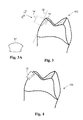
- Fig. 2 shows such an averaged plane 12 defined on a tooth of the tooth model 100 and which is perpendicular to the resulting vector 13.
- Fig. 3 the tooth model 100 is shown with an outline 14 of a bracket head determined on the tooth model 100.
- the bracket head outline 14 is determined by a projection of a preliminary bracket head outline 14' provided in the averaged plane 12 or a virtual plane which is parallel to the averaged plane 12.
- the preliminary bracket head outline 14 is retrieved from a library holding a plurality of different preliminary bracket head outlines.
- the preliminary bracket head outlines in the library may be standardized and available for bracket types having one, two, three or four tie wings.
- Fig. 3A shows such a standardized preliminary bracket head outline for defining the outer contour of a single tie wing for the bracket.
- Fig. 4 shows an offset 15 of the bracket head outline 14.
- the offset 15 is obtained from a parallel offset based on the averaged plane 12 (shown in Fig. 3 ).
- a tie wing may be created based on the offset 15 and the bracket head outline 14 in a similar manner as described for the bracket base above.
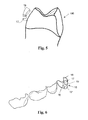
- Fig. 5 shows a (virtual) tie wing 16 positioned relative to a virtual bracket body 17.
- the bracket body 17 may be obtained from a library holding a plurality of different standardized bracket bodies.
- the bracket body is positioned relative to the tooth model 100.
- Such position can be derived from a position of a virtual archwire located to a virtual model of the patient's dentition in the desired and/or the initial position.
- the archwire may be designed according to the so-called straight wire technique at a minimized distance to the lingual or labial sides of the teeth of the dentition. In the straight wire technique the archwire extends generally in a plane although it is curved in a U-shape.
- the slot of the virtual bracket body may be appropriately positioned relative to the archwire and the remainder of the body may be user-positioned such that the body extends substantially through a middle area of the bracket receiving area on the tooth model 100.
- a method of making a bracket by combining a virtual bracket body and a virtual bracket pad or base as it may be also used for the present invention is for example disclosed in more detail in EP 1 474 064 B1 .
- the tie wing 16 may be user-positioned (as illustrated) using CAD functionality.
- the tooth shaped surfaces of the tie wing 16 are preferably parallel offset from the corresponding area portions of the tooth model 100, whereas the three-dimensional position of the tie wing 16 may be determined by the user by moving the tie wing to a desired location.
- the orientation of the tie wing 16 may be fixed whereas the three-dimensional position of the tie wing 16 may be variable.
- the fixation of the orientation of the tie wing 16 may be switchable on or off so that a change of the orientation is enabled to the user.
- tie wing 16 Once the tie wing 16 is appropriately positioned the tie wing 16 and the body 17 may be merged by computer aid. A further tie wing 17' (shown in Fig. 6 ) may be obtained in an identical manner.
- Fig. 6 shows a virtual orthodontic bracket 10 having two tie wings 17, 17', a bracket base 18, a bracket body 16 and an archwire slot 19.
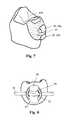
- the virtual orthodontic bracket 10 may be provided to a manufacturing machine in the form of computer processible data. Such a machine may be used to create the physical orthodontic bracket as shown in Fig. 7 .
- the entire customized orthodontic bracket may be made as one single piece by use of Selective Laser Melting.
- Fig. 7 shows the finished physical orthodontic bracket 20 attached to a patient's tooth 200.
- an adhesive or cement may be used for attachment of the bracket 20 to the tooth 200.
- a suitable cement is for example available under the designation RelyX TM Unicem Self-Adhesive Resin Cement, from 3M Deutschland GmbH.
- the tie wings 26, 26' exhibit bracket head surfaces 26a, 26a' which follow the shape of the tooth 20 in an area beneath the tie wings.
- the bracket of the invention helps minimizing any discomfort for the patient undergoing an orthodontic treatment.
- Fig. 8 shows a ligature 30 tied over the tie wings 26, 26a and affixing an archwire 40 to the bracket 20.
Priority Applications (9)
| Application Number | Priority Date | Filing Date | Title |
|---|---|---|---|
| EP13180393.4A EP2837356A1 (de) | 2013-08-14 | 2013-08-14 | Orthodontische Brackets und Verfahren zur Herstellung eines orthodontischen Brackets |
| MX2016001833A MX2016001833A (es) | 2013-08-14 | 2014-08-13 | Aparato de ortodoncia y metodo para fabricar un aparato de ortodoncia. |
| CN201480045165.9A CN105473101B (zh) | 2013-08-14 | 2014-08-13 | 正畸托槽和制备正畸托槽的方法 |
| BR112016002938A BR112016002938A2 (pt) | 2013-08-14 | 2014-08-13 | método de fabricação de um bráquete ortodôntico personalizado, bráquete ortodôntico personalizado e kit de bráquetes ortodônticos personalizados |
| PCT/US2014/050940 WO2015023784A1 (en) | 2013-08-14 | 2014-08-13 | An orthodontic bracket and a method of making an orthodontic bracket |
| KR1020167006159A KR20160042965A (ko) | 2013-08-14 | 2014-08-13 | 치과교정용 브래킷 및 치과교정용 브래킷의 제조 방법 |
| JP2016534820A JP2016527993A (ja) | 2013-08-14 | 2014-08-13 | 歯科矯正ブラケット及び歯科矯正ブラケット製造方法 |
| EP14755755.7A EP3033037B1 (de) | 2013-08-14 | 2014-08-13 | Verfahren zur herstellung eines orthodontischen brackets |
| US14/911,705 US9949804B2 (en) | 2013-08-14 | 2014-08-13 | Orthodontic bracket and a method of making an orthodontic bracket |
Applications Claiming Priority (1)
| Application Number | Priority Date | Filing Date | Title |
|---|---|---|---|
| EP13180393.4A EP2837356A1 (de) | 2013-08-14 | 2013-08-14 | Orthodontische Brackets und Verfahren zur Herstellung eines orthodontischen Brackets |
Publications (1)
| Publication Number | Publication Date |
|---|---|
| EP2837356A1 true EP2837356A1 (de) | 2015-02-18 |
Family
ID=48985625
Family Applications (2)
| Application Number | Title | Priority Date | Filing Date |
|---|---|---|---|
| EP13180393.4A Ceased EP2837356A1 (de) | 2013-08-14 | 2013-08-14 | Orthodontische Brackets und Verfahren zur Herstellung eines orthodontischen Brackets |
| EP14755755.7A Active EP3033037B1 (de) | 2013-08-14 | 2014-08-13 | Verfahren zur herstellung eines orthodontischen brackets |
Family Applications After (1)
| Application Number | Title | Priority Date | Filing Date |
|---|---|---|---|
| EP14755755.7A Active EP3033037B1 (de) | 2013-08-14 | 2014-08-13 | Verfahren zur herstellung eines orthodontischen brackets |
Country Status (8)
| Country | Link |
|---|---|
| US (1) | US9949804B2 (de) |
| EP (2) | EP2837356A1 (de) |
| JP (1) | JP2016527993A (de) |
| KR (1) | KR20160042965A (de) |
| CN (1) | CN105473101B (de) |
| BR (1) | BR112016002938A2 (de) |
| MX (1) | MX2016001833A (de) |
| WO (1) | WO2015023784A1 (de) |
Cited By (3)
| Publication number | Priority date | Publication date | Assignee | Title |
|---|---|---|---|---|
| CN105852995A (zh) * | 2016-04-27 | 2016-08-17 | 叶年嵩 | 一种个性化舌侧托槽矫治器及其制作方法 |
| EP3831330A1 (de) * | 2019-12-04 | 2021-06-09 | Oxilio Ltd | Systeme und verfahren zur erzeugung einer 3d-darstellung von einer orthodontischen festen zahnspange |
| CN114052955A (zh) * | 2021-12-01 | 2022-02-18 | 浙江工业大学 | 一种基于压模成型的个性化舌侧托槽及其制作方法 |
Families Citing this family (16)
| Publication number | Priority date | Publication date | Assignee | Title |
|---|---|---|---|---|
| EP2907476A1 (de) * | 2014-02-12 | 2015-08-19 | 3M Innovative Properties Company | Verfahren zur Herstellung eines individuell angepassten orthodontischen Brackets |
| CN106031661A (zh) * | 2015-03-17 | 2016-10-19 | 首都医科大学附属北京口腔医院 | 一种口腔正畸支抗体 |
| KR20190037241A (ko) * | 2016-07-28 | 2019-04-05 | 케어스트림 덴탈 테크놀로지 톱코 리미티드 | 치열 메시 브레이스 제거를 위한 방법 및 시스템 |
| CN110087577B (zh) | 2016-11-30 | 2022-11-08 | 登塔尔图像科技公司 | 用于从牙列网格去除牙箍的方法和系统 |
| JP7223704B2 (ja) * | 2017-03-15 | 2023-02-16 | スリーエム イノベイティブ プロパティズ カンパニー | 歯科器具及び歯科器具の自動製造システムの作動方法 |
| US11564778B2 (en) * | 2018-03-07 | 2023-01-31 | TH!NK Innovations, LLC | Orthodontic elastic attachments for use with dental aligners |
| US11701203B2 (en) * | 2018-06-29 | 2023-07-18 | Align Technology, Inc. | Dental appliance hook placement and visualization |
| US10278794B1 (en) | 2018-09-28 | 2019-05-07 | 3D Med Ag | Systems and methods for making orthodontic brackets |
| KR102181712B1 (ko) * | 2019-08-14 | 2020-11-23 | 주식회사 디오 | 치열교정용 와이어 고정브라켓 |
| US10631956B1 (en) | 2019-12-04 | 2020-04-28 | Oxilio Ltd | Methods and systems for making an orthodontic aligner having fixing blocks |
| US10726949B1 (en) | 2019-12-05 | 2020-07-28 | Oxilio Ltd | Systems and methods for generating 3D-representation of tooth-specific platform for dental appliance |
| EP4267034A1 (de) * | 2020-12-23 | 2023-11-01 | Hirsch Dynamics Holding AG | Automatische erstellung eines virtuellen modells von mindestens einem teil einer orthodontischen vorrichtung |
| WO2022135717A1 (en) * | 2020-12-23 | 2022-06-30 | Hirsch Dynamics Holding Ag | Automatic creation of a virtual model of at least a bonding part of an orthodontic bracket |
| KR102537012B1 (ko) * | 2023-02-17 | 2023-05-30 | 주식회사 올소비트 | 치아교정을 위한 임상학적 치열궁을 수치적으로 측정하여 결정하는 방법 |
| KR102537014B1 (ko) * | 2023-02-17 | 2023-05-30 | 주식회사 올소비트 | 수치로 측정한 임상학적 치열궁을 바탕으로 가이드 일체형 브라켓을 제조하는 방법과 그로 인하여 제조된 가이드 일체형 브라켓 |
| KR102537013B1 (ko) * | 2023-02-17 | 2023-05-30 | 주식회사 올소비트 | 수치로 측정한 임상학적 치열궁을 바탕으로 기성품 브라켓 부착용 가이드를 제조하는 방법과 그로 인하여 제조된 가이드 |
Citations (3)
| Publication number | Priority date | Publication date | Assignee | Title |
|---|---|---|---|---|
| WO2001080761A2 (en) * | 2000-04-19 | 2001-11-01 | Orametrix, Inc. | Interactive orthodontic care system based on intra-oral scanning of teeth |
| EP1474064B1 (de) | 2002-02-13 | 2008-11-19 | T.O.P. Service für Lingualtechnik GmbH | Modularsystem für kundengebundene orthodontische vorrichtungen |
| US20100324715A1 (en) * | 2008-02-27 | 2010-12-23 | Yongqiang Yang | Direct manufacturing method of selective laser melting of customized tongue-side orthodontic support grooves |
Family Cites Families (5)
| Publication number | Priority date | Publication date | Assignee | Title |
|---|---|---|---|---|
| US5607301A (en) * | 1994-11-01 | 1997-03-04 | Lancer Orthodontics | Orthodontic bracket and method of mounting |
| CN101284302B (zh) * | 2008-02-27 | 2011-06-15 | 华南理工大学 | 个性化舌侧正畸托槽的选区激光烧结间接制造方法 |
| CN101647729B (zh) * | 2009-09-11 | 2012-11-14 | 广州瑞通生物科技有限公司 | 个性化舌侧正畸矫治器的制造方法 |
| CA2802867A1 (en) | 2010-07-28 | 2012-02-02 | Udo Hoss | Analyte sensors having temperature independent membranes |
| CN103027755A (zh) * | 2012-12-13 | 2013-04-10 | 广州瑞通生物科技有限公司 | 一种个性化舌侧自锁矫治器 |
-
2013
- 2013-08-14 EP EP13180393.4A patent/EP2837356A1/de not_active Ceased
-
2014
- 2014-08-13 MX MX2016001833A patent/MX2016001833A/es unknown
- 2014-08-13 BR BR112016002938A patent/BR112016002938A2/pt not_active Application Discontinuation
- 2014-08-13 WO PCT/US2014/050940 patent/WO2015023784A1/en active Application Filing
- 2014-08-13 EP EP14755755.7A patent/EP3033037B1/de active Active
- 2014-08-13 US US14/911,705 patent/US9949804B2/en active Active
- 2014-08-13 KR KR1020167006159A patent/KR20160042965A/ko not_active Application Discontinuation
- 2014-08-13 JP JP2016534820A patent/JP2016527993A/ja active Pending
- 2014-08-13 CN CN201480045165.9A patent/CN105473101B/zh active Active
Patent Citations (4)
| Publication number | Priority date | Publication date | Assignee | Title |
|---|---|---|---|---|
| WO2001080761A2 (en) * | 2000-04-19 | 2001-11-01 | Orametrix, Inc. | Interactive orthodontic care system based on intra-oral scanning of teeth |
| EP1474064B1 (de) | 2002-02-13 | 2008-11-19 | T.O.P. Service für Lingualtechnik GmbH | Modularsystem für kundengebundene orthodontische vorrichtungen |
| US20120015315A1 (en) | 2002-02-13 | 2012-01-19 | 3M Innovative Properties Company | Customized orthodontic bracket system |
| US20100324715A1 (en) * | 2008-02-27 | 2010-12-23 | Yongqiang Yang | Direct manufacturing method of selective laser melting of customized tongue-side orthodontic support grooves |
Cited By (5)
| Publication number | Priority date | Publication date | Assignee | Title |
|---|---|---|---|---|
| CN105852995A (zh) * | 2016-04-27 | 2016-08-17 | 叶年嵩 | 一种个性化舌侧托槽矫治器及其制作方法 |
| CN105852995B (zh) * | 2016-04-27 | 2018-08-07 | 叶年嵩 | 一种个性化舌侧托槽矫治器及其制作方法 |
| EP3831330A1 (de) * | 2019-12-04 | 2021-06-09 | Oxilio Ltd | Systeme und verfahren zur erzeugung einer 3d-darstellung von einer orthodontischen festen zahnspange |
| US11273008B2 (en) | 2019-12-04 | 2022-03-15 | Oxilio Ltd | Systems and methods for generating 3D-representation of tooth-specific appliance |
| CN114052955A (zh) * | 2021-12-01 | 2022-02-18 | 浙江工业大学 | 一种基于压模成型的个性化舌侧托槽及其制作方法 |
Also Published As
| Publication number | Publication date |
|---|---|
| BR112016002938A2 (pt) | 2017-08-01 |
| KR20160042965A (ko) | 2016-04-20 |
| US9949804B2 (en) | 2018-04-24 |
| CN105473101B (zh) | 2019-07-16 |
| EP3033037A1 (de) | 2016-06-22 |
| CN105473101A (zh) | 2016-04-06 |
| US20160199154A1 (en) | 2016-07-14 |
| MX2016001833A (es) | 2016-04-15 |
| JP2016527993A (ja) | 2016-09-15 |
| EP3033037B1 (de) | 2020-05-06 |
| WO2015023784A1 (en) | 2015-02-19 |
Similar Documents
| Publication | Publication Date | Title |
|---|---|---|
| EP3033037B1 (de) | Verfahren zur herstellung eines orthodontischen brackets | |
| AU2020277085B2 (en) | Treatment plan specific bite adjustment structures | |
| US10292789B2 (en) | Tooth positioning appliance with curved interconnecting elements | |
| US10314673B2 (en) | System for producing a one-piece orthodontic jig and brackets | |
| CA3017314C (en) | Tooth-positioning appliance for closing spaces | |
| US20190125494A1 (en) | Alternative bite adjustment structures | |
| US20190321136A1 (en) | Tooth-positioning appliance, systems and methods of producing and using the same | |
| JP6005700B2 (ja) | 歯列矯正装具用のラピッドプロトタイプ移動トレー | |
| KR20150048882A (ko) | 후속 치과 기구를 형성하는데 사용가능한 방법 및 시스템 | |
| CN111182849B (zh) | 包括弹簧构件的可移除牙科器具 | |
| US20200375698A1 (en) | Removable dental appliance including positioning member | |
| WO2020236822A1 (en) | Tooth-positioning appliance, systems and methods of producing and using the same | |
| US20240099817A1 (en) | Prescription attachments for removable dental appliances | |
| AU2016203563B2 (en) | Tooth positioning appliance with curved interconnecting elements | |
| CA2932100C (en) | Tooth positioning appliance with curved interconnecting elements | |
| EP3267924B1 (de) | Zahnpositionierungsgerät zum schliessen von räumen |
Legal Events
| Date | Code | Title | Description |
|---|---|---|---|
| 17P | Request for examination filed |
Effective date: 20130814 |
|
| AK | Designated contracting states |
Kind code of ref document: A1 Designated state(s): AL AT BE BG CH CY CZ DE DK EE ES FI FR GB GR HR HU IE IS IT LI LT LU LV MC MK MT NL NO PL PT RO RS SE SI SK SM TR |
|
| AX | Request for extension of the european patent |
Extension state: BA ME |
|
| PUAI | Public reference made under article 153(3) epc to a published international application that has entered the european phase |
Free format text: ORIGINAL CODE: 0009012 |
|
| STAA | Information on the status of an ep patent application or granted ep patent |
Free format text: STATUS: THE APPLICATION HAS BEEN REFUSED |
|
| 18R | Application refused |
Effective date: 20150528 |