EP2837329A1 - Bicycle fitting system - Google Patents
Bicycle fitting system Download PDFInfo
- Publication number
- EP2837329A1 EP2837329A1 EP14164205.8A EP14164205A EP2837329A1 EP 2837329 A1 EP2837329 A1 EP 2837329A1 EP 14164205 A EP14164205 A EP 14164205A EP 2837329 A1 EP2837329 A1 EP 2837329A1
- Authority
- EP
- European Patent Office
- Prior art keywords
- bicycle
- controller
- rider
- angle
- led
- Prior art date
- Legal status (The legal status is an assumption and is not a legal conclusion. Google has not performed a legal analysis and makes no representation as to the accuracy of the status listed.)
- Granted
Links
- VCRAOBCIIXVYIE-UHFFFAOYSA-N CC(C)(CCC1CCCCC2)C1C1CC2C(C)(C)CC(CC2)CS(CO)C2C1 Chemical compound CC(C)(CCC1CCCCC2)C1C1CC2C(C)(C)CC(CC2)CS(CO)C2C1 VCRAOBCIIXVYIE-UHFFFAOYSA-N 0.000 description 1
Images




Classifications
-
- A—HUMAN NECESSITIES
- A63—SPORTS; GAMES; AMUSEMENTS
- A63B—APPARATUS FOR PHYSICAL TRAINING, GYMNASTICS, SWIMMING, CLIMBING, OR FENCING; BALL GAMES; TRAINING EQUIPMENT
- A63B69/00—Training appliances or apparatus for special sports
- A63B69/16—Training appliances or apparatus for special sports for cycling, i.e. arrangements on or for real bicycles
-
- B—PERFORMING OPERATIONS; TRANSPORTING
- B23—MACHINE TOOLS; METAL-WORKING NOT OTHERWISE PROVIDED FOR
- B23P—METAL-WORKING NOT OTHERWISE PROVIDED FOR; COMBINED OPERATIONS; UNIVERSAL MACHINE TOOLS
- B23P21/00—Machines for assembling a multiplicity of different parts to compose units, with or without preceding or subsequent working of such parts, e.g. with program control
-
- A—HUMAN NECESSITIES
- A61—MEDICAL OR VETERINARY SCIENCE; HYGIENE
- A61B—DIAGNOSIS; SURGERY; IDENTIFICATION
- A61B5/00—Measuring for diagnostic purposes; Identification of persons
- A61B5/103—Measuring devices for testing the shape, pattern, colour, size or movement of the body or parts thereof, for diagnostic purposes
- A61B5/11—Measuring movement of the entire body or parts thereof, e.g. head or hand tremor or mobility of a limb
- A61B5/1126—Measuring movement of the entire body or parts thereof, e.g. head or hand tremor or mobility of a limb using a particular sensing technique
- A61B5/1127—Measuring movement of the entire body or parts thereof, e.g. head or hand tremor or mobility of a limb using a particular sensing technique using markers
-
- A—HUMAN NECESSITIES
- A63—SPORTS; GAMES; AMUSEMENTS
- A63B—APPARATUS FOR PHYSICAL TRAINING, GYMNASTICS, SWIMMING, CLIMBING, OR FENCING; BALL GAMES; TRAINING EQUIPMENT
- A63B71/00—Games or sports accessories not covered in groups A63B1/00 - A63B69/00
- A63B71/06—Indicating or scoring devices for games or players, or for other sports activities
Definitions
- the present invention generally relates to a bicycle fitting system.
- the present invention relates to a bicycle fitting system for a bicycle fitting.
- Conventional bicycle fitting systems measures rider body sizes of a rider, and adjusts bicycle components of a bicycle based on the rider body sizes.
- a conventional bicycle fitting system utilizes a three-dimensional marker tracking system that detects markers attached to a rider body for measuring rider body sizes of the rider (see U.S. Patent Application Publication No. 2007/0142177 A1 , for example).
- the bicycle components need to be properly adjusted for obtaining a suitable riding posture for the rider.
- a suitable riding posture of a rider since the suitable riding posture varies according to rider body characteristics, bicycle types, riding types or the like.
- One object of the disclosure is to provide a bicycle fitting system with which a suitable position of a bicycle component can be obtained for each rider.
- a bicycle fitting system includes a controller programmed to determine whether a current rider position of a rider is appropriate based on a flexibility level of a rider body of the rider.
- the bicycle fitting system further includes a motion capturing apparatus electrically connected to the controller.
- the controller is further programmed to determine the flexibility level using the motion capturing apparatus.
- the controller is programmed to measure a plurality of rider body parameters of the rider body using the motion capturing apparatus while the rider is on a bicycle fitting equipment.
- the controller is programmed to set a parameter range of one of the rider body parameters based on the flexibility level, and output a bicycle fitting information based on both the rider body parameters and the parameter range of the one of the rider body parameters.
- the bicycle fitting information indicates a bicycle component position of a bicycle component.
- the bicycle fitting information indicates whether the one of the rider body parameters falls within the parameter range of the one of the rider body parameters.
- the controller is programmed to acquire category information indicative of at least one of a bicycle type and a riding type, and to set the parameter range of the one of the rider body parameters based on the flexibility level and the category information.
- the controller is programmed to determine a setting position of at least one of a bicycle seat and a bicycle handle as the bicycle component position.
- the controller is programmed to determine a temporal bicycle component position of a bicycle component based on the rider body parameters in response to the one of the rider body parameters falling outside the parameter range of the one of the rider body parameters.
- the bicycle fitting equipment is adjusted based on the temporal bicycle component position.
- the controller is programmed to output the bicycle component position on an output apparatus.
- the controller is programmed to acquire an initial bicycle component position of the bicycle component.
- the controller is preferably programmed to output the bicycle component position and the initial bicycle component position.
- the controller is programmed to determine an adjustment direction of the bicycle component and an adjustment amount of the bicycle component based on the bicycle component position.
- the controller is preferably programmed to output the adjustment direction and the adjustment amount on an output apparatus.
- the controller is programmed to display an indicator with a first predetermined status in response to the one of the rider body parameters falling within the parameter range of the one of the rider body parameters on a display screen.
- the controller is preferably programmed to display the indicator with a second predetermined status in response to the one of the rider body parameters falling outside the parameter range of the one of the rider body parameters on the display screen.
- the second predetermined status is different from the first predetermined status.
- a bicycle fitting system 10 is illustrated in accordance with a first embodiment.
- the bicycle fitting system 10 includes a controller 12.
- the bicycle fitting system 10 also includes a motion capturing apparatus 14 electrically connected to the controller 12.
- the bicycle fitting system 10 determines whether a current rider position of a rider is appropriate while the rider is riding on a bicycle fitting equipment 16.
- the controller 12 is programmed to measure a plurality of rider body parameters of a rider body 18 using the motion capturing apparatus 14 while the rider is on the bicycle fitting equipment 16.
- the controller 12 is further programmed to determine bicycle component positions of bicycle components.
- the controller 12 determines a suitable seat position and a suitable handlebar position.
- the controller 12 can also be configured to determine bicycle component positions other than the suitable seat position and the suitable handlebar position. The configurations of the controller 12 will be explained later in detail.
- the bicycle fitting equipment 16 is equipment that makes it possible to simulate a bicycle riding while remaining stationary.
- the bicycle fitting equipment 16 includes a stand or frame 22, a handlebar 24 (e.g., a bicycle handle), a seat or saddle 26 (e.g., a bicycle seat), a crank assembly 28, a rear wheel 30 and a resistance unit 32.
- the handlebar 24 and the seat 26 are adjustably coupled to the frame 22 in a conventional manner.
- the handlebar 24 and the seat 26 are adjustable with respect to the frame 22 in a horizontal direction X and in a vertical direction Y perpendicular to the horizontal direction X.
- the handlebar 24 is adjustably supported to the frame 22 by an adjustable handlebar support 34.
- the adjustable handlebar support 34 is operatively disposed between the frame 22 and the handlebar 24.
- the adjustable handlebar support 34 has a horizontal part horizontally slidable with respect to the frame 22, and a vertical part vertically slidable with respect to the horizontal part.
- the seat 26 is also adjustably supported by an adjustable seat support 36 in the horizontal direction X and in the vertical direction Y.
- the handlebar 24 and the seat 26 are manually adjustable with respect to the frame 22.
- the adjustable handlebar support 34 has scales indicative of current handlebar positions in the horizontal direction X and in the vertical direction Y, respectively, with respect to a reference position or origin of the frame 22.
- the adjustable seat support 36 has scales indicative of current seat positions in the horizontal direction X and in the vertical direction Y, respectively, with respect to the reference position or origin of the frame 22.
- the handlebar 24 and the seat 26 are manually adjustable with respect to the frame 22.
- the bicycle fitting equipment 16 can include an electrical drive unit for automatically and electrically adjusting the handlebar 24 and the seat 26 in the horizontal direction X and the vertical direction Y.
- the bicycle fitting equipment 16 can be electrically connected to the controller 12 to output adjustment data indicative of handlebar adjustment amounts in the horizontal direction X and in the vertical direction Y, and adjustment data indicative of seat adjustment amounts in the horizontal direction X and in the vertical direction Y.
- the adjustable handlebar support 34 has sensors to detect the handlebar adjustment amounts of the handlebar 24 with respect to the frame 22 in the horizontal direction X and in the vertical direction Y, and outputs the adjustment data indicative of the handlebar adjustment amounts to the controller 12.
- the adjustable seat support 36 has sensors to detect the seat adjustment amounts of the seat 26 with respect to the frame 22 in the horizontal direction X and in the vertical direction Y, and outputs the adjustment data indicative of the seat adjustment amounts to the controller 12.
- the crank assembly 28 is rotatably supported to the frame 22 by a bottom bracket part.
- the crank assembly 28 has a pair of crank arms 38.
- Each of the crank arms 38 includes a pedal 40 that is mounted to the free end of a respective one of the crank arms 38.
- the crank arms 38 have inner ends fixed to opposite ends a crank axle 42, with the crank arms 38 extending in opposite radial directions from the crank axle 42.
- the crank axle 42 has a center axis that defines the origin of an orthogonal coordinate system with axes extending in the horizontal direction X and in the vertical direction Y, respectively.
- the center axis of the crank axle 42 is perpendicular to the horizontal direction X and the vertical direction Y.
- the center axis of the crank axle 42 is a rotational axis, and coincident with a center axis of the bottom bracket.
- the rear wheel 30 is rotatably supported to the frame 22.
- the rear wheel 30 is operatively coupled to the crank assembly 28 via a drive train that transmits pedaling force applied to the crank assembly 28 to the rear wheel 30 to rotate the rear wheel 30.
- the resistance unit 32 provides resistance on the rear wheel 30.
- the resistance unit 32 can be a conventional unit used in bicycle trainers or the like, such as a unit creating the resistance by a wind, a magnet, fluid or the like. The detailed configurations of the resistance unit 32 will be omitted for the sake of brevity.
- the bicycle fitting equipment 16 can be formed without the rear wheel 30 and the resistance unit 32.
- the bicycle fitting equipment 16 can be any other types of stationary bicycles (e.g., adjustable stationary cycling machines), or bicycle trainers that make it possible to ride a bicycle while it remains stationary.
- the motion capturing apparatus 14 is configured to detect markers M1 to M8 attached near joints of the rider body 18 of the rider to identify positions of the rider body 18 and a bicycle riding posture of the rider body 18.
- the markers M1 to M8 are made by LEDs (Light Emitting Diodes), respectively, in this embodiment.
- the markers M1 to M8 are referred to as LEDs M1 to M8, respectively.
- the markers M1 to M8 can be made by light sources other than the LEDs, reflectors or specific color members.
- the motion capturing apparatus 14 is also configured to output the detection results to the controller 12. In the illustrated embodiment, a conventional motion capturing apparatus can be used as the motion capturing apparatus 14.
- the motion capturing apparatus 14 has an image sensor or camera 44 that detects the LEDs M1 to M8.
- the LEDs M1 to M8 are powered and actuated electrically through a wiring (not shown), and actively illuminated.
- the LEDs M1 to M8 can be powered and actuated by batteries which are installed in housings of the LEDs M1 to M8, respectively.
- the motion capturing apparatus 14 uses an active marker system for motion capture.
- any other types of motion capturing system such as a system using an acoustic, inertial, magnetic or reflective markers, can be used as the motion capturing apparatus 14.
- the LEDs M1 to M8 are attached to the rider body 18.
- the attachments can be performed by a conventional means, such as a double-sided adhesive tape, a hook-and-loop fastener, an elastic band, or the like.
- the LEDs M1 to M8 are non-movably attached to the rider body 18 on the joints of the rider body 18 in a visible manner.
- the camera 44 of the motion capturing apparatus 14 detects the rider position by capturing images of the rider body 18 on the right side.
- the LEDs M1 to M8 are attached to the following locations on the right outside of the rider body 18.
- the LED M1 is located at a center between the thenar of a rider foot and the hypothenar of the rider foot as viewed from the right outside of the rider body 18.
- the LED M2 is located at the heel of the rider foot.
- the LED M3 is located at the malleous or ankle of the rider foot.
- the LED M4 is located at the knee joint of a rider leg.
- the LED M5 is located at the greater trochanter of the rider body 18.
- the LED M6 is located at the acromio of the rider body 18.
- the LED M7 is located at the elbow joint of a rider arm.
- the LED M8 is located at the radiocarpal jaw of the rider arm.
- the locations of the LEDs M1 to M8 are merely examples.
- the LEDs M1 to M8 can be attached to alternative locations from the above-mentioned locations. Furthermore, additional LEDs can be further used. In the illustrated embodiment, the LEDs M1 to M8 can be directly attached to the rider body 18 at locations where the rider body 18 is exposed. However, the LEDs M1 to M8 can also be attached on a surface of clothing, a sock, or a shoe at locations where the rider body 18 is not exposed.
- the motion capturing apparatus 14 detects the LEDs M1 to M8 to determine the current rider position of the rider.
- the camera 44 of the motion capturing apparatus 14 is electrically coupled to a computer system 46.
- the computer system 46 has a motion capturing software that calculates relative positions of the LEDs M1 to M8 (e.g., distances or directions between pairs selected from the LEDs M1 to M8) in the orthogonal coordinate system with the axes extending in the horizontal direction X and in the vertical direction Y, respectively, based on the captured images by the camera 44.
- the computer system 46 can be configured to detect absolute positions or coordinates of the LEDs M1 to M8 in the orthogonal coordinate system with the axes extending in the horizontal direction X and in the vertical direction Y, respectively, based on the captured images by the camera 44.
- the computer system 46 also forms the controller 12.
- the motion capturing apparatus 14 can include a separate computer system that is electrically connected from the computer system 46 and that provides the calculated positions of the LEDs M1 to M8 to the computer system 46.
- the computer system 46 forms the controller 12, and includes a microcomputer, a computer readable medium (e.g., memory, hard disk, etc.) with one or more executable control programs stored thereon or is communicable with such a computer readable medium in order to execute the control program(s).
- the computer system 46 also preferably includes other conventional components such as an input interface circuit, an output interface circuit, and storage devices such as a ROM (Read Only Memory) device and a RAM (Random Access Memory) device to store programming, data, calculations and/or results.
- the microcomputer of the computer system 46 forms the controller 12, and is programmed to send control commands to and/or receive information from the motion capturing apparatus 14, as explained above.
- the precise structure and algorithms for the controller 12 can be any combination of hardware and software that will carry out the functions of the present disclosure.
- the computer system 46 is illustrated as a laptop personal computer. However, the computer system 46 can be any other types of computer, such as a desktop computer, or a bicycle computer.
- the computer system 46 includes a display screen 48.
- the controller 12 is programmed to determine whether a current rider position of the rider is appropriate based on a flexibility level of the rider body 18 of the rider. Specifically, in the illustrated embodiment, the controller 12 determines whether the current rider position of the ride is appropriate while the rider is on the bicycle fitting equipment 16, and determines a suitable handlebar position of the handlebar 24 and a suitable seat position of the seat 26 for the rider when the current rider position of the rider matches with a predetermined condition described later.
- the controller 12 is further programmed to determine the flexibility level using the motion capturing apparatus 14. Specifically, in the illustrated embodiment, the controller 12 determines the flexibility level of the rider body 18 while the rider lies on the back.
- Figure 2 illustrates a schematic image of the rider body 18.
- the controller 12 calculates a hip angle ⁇ a and a knee angle ⁇ b, respectively, based on the positions of the LEDs M3 to M5 and M6 determined by the motion capturing apparatus 14.
- the hip angle ⁇ a is calculated as an angle at the LED M5 enclosed by the lines from the LED M5 to the LED M4 and the LED M5 to the LED M6.
- the hip angle ⁇ a is calculated while the rider pulls the thigh towards the chest as close as possible.
- the knee angle ⁇ b is calculated as an angle at the LED M4 enclosed by the lines from the LED M4 to the LED M5 and the LED M4 to the LED M3.
- the knee angle ⁇ b is calculated while the rider straightens the knee as much as possible.
- a hip flexibility level of the hip angle ⁇ a is determined based on a hip flexibility table 52, while a knee flexibility level of the knee angle ⁇ b is determined on a knee flexibility table 54.
- the hip flexibility level of the hip angle ⁇ a is classified into three categories, such as "Good” (e.g., a first category), "Fair” (e.g., a second category) and "Stiff” (e.g., a third category), according to the hip angle ⁇ a.
- the hip flexibility level is determined as "Good.” Furthermore, if the hip angle ⁇ a falls within a range of XX2 degree to XX3 degree, then the hip flexibility level is determined as "Fair.” Moreover, if the hip angle ⁇ a falls within a range of XX3 degree to XX4 degree, then the hip flexibility level is determined as "Stiff.” On the other hand, in the illustrated embodiment, the knee flexibility level of the knee angle ⁇ b is classified into three categories, such as “Good”, “Fair” and "Stiff", according to the knee angle ⁇ b.
- the knee flexibility level is determined as "Good.” Furthermore, if the knee angle ⁇ b falls within a range of YY2 degree to YY3 degree, then the knee flexibility level is determined as "Fair.” Moreover, if the knee angle ⁇ b falls within a range of YY3 degree to YY4 degree, then the knee flexibility level is determined as "Stiff.” Then, the controller 12 stores the hip flexibility level and the knee flexibility level in a memory of the computer system 46.
- the thresholds XX1, XX2, XX3, XX4, YY1, YY2, YY3, and YY4 are not described in the illustrated embodiment. However, it will be apparent to those skilled in the art from this disclosure that these thresholds can be experimentally predetermined.
- the threshold XX1 is a smaller value than the threshold XX2
- the threshold XX2 is a smaller value than the threshold XX3
- the threshold XX3 is a smaller value than the threshold XX4.
- the threshold YY1 is a larger value than the threshold YY2
- the threshold YY2 is a larger value than the threshold YY3
- the threshold YY3 is a larger value than the threshold YY4.
- the hip flexibility level and the knee flexibility level are determined as the flexibility level of the present application.
- flexibility levels for other locations can be alternatively or additionally determined.
- the hip and knee flexibility levels are classified into three categories, respectively. However, the number of categories can be less than or more than three.
- the controller 12 determines the flexibility level of the rider body 18 while the rider lies on the back.
- the controller 12 can determine the flexibility level of the rider body 18 in a different manner, such as while the rider is standing.
- the controller 12 can merely obtain the flexibility level of the rider body 18 without measurements of the rider body 18 by the motion capturing apparatus 14. For example, if the flexibility level of the rider body 18 is measured in a conventional manner, then the flexibility level of the rider body 18 can be manually or electrically inputted to the computer system 46 of the controller 12.
- the controller 12 is programmed to measure the rider body parameters of the rider body 18 using the motion capturing apparatus 14 while the rider is on the bicycle fitting equipment 16. In the illustrated embodiment, the controller 12 measures the rider body parameters of the rider body 18 based on the relative positions of the LEDs M1 to M8.
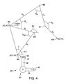
- the rider body parameters of the rider body 18 include a first length 11, a second length 12, a third length 13, a fourth length 14, a fifth length 15, a first deviation s, a second deviation t, a lower leg angle ⁇ 1, an upper leg angle ⁇ 2, a knee angle ⁇ n, a hip angle ⁇ h, an armpit angle ⁇ 4 and an elbow angle ⁇ 5.
- the controller 12 measures the rider body parameters of the rider body 18 while the rider is on the bicycle fitting equipment 16, and is pedaling the crank assembly 28.
- the controller 12 starts measuring the rider body parameters of the rider body 18 once the pedaling or cadence becomes stable.
- the controller 12 measures a set of the rider body parameters of the rider body 18 while the rider rotates the crank assembly 28 several times, e.g. ten times.
- the controller 12 can measure the set of the rider body parameters while the rider rotates the crank assembly 28 less than or more than ten times, as needed and/or desired.
- the controller 12 measures the rider body parameters of the rider body 18 as follows.
- the first length 11 is defined as a distance between the LED M3 and the LED M4.
- the second length 12 is defined as a distance between the LED M4 and the LED M5.
- the third length 13 is defined as a distance between the LED M5 and the LED M6.
- the fourth length 14 is defined as a distance between the LED M6 and the LED M7.
- the fifth length 15 is defined as a distance between the LED M7 and the LED M8.
- the first deviation s is defined as a distance between the LED M1 and the LED M4 in the horizontal direction X when the crank arm 38 of the crank assembly 28 is horizontally oriented and the position of the LED M4 in the horizontal direction X has the maximum value.
- the second deviation t is defined as a distance between the LED M1 and the LED M3 in the horizontal direction X.
- the controller 12 calculates an average value of the distances between the LED M3 and the LED M4 that are measured while the rider rotates the crank assembly 28 ten times, and determines the average value of the distances as the first length 11. Also, the controller 12 determines the second to fifth lengths 12 to 15, the first deviation s and the second deviation t in the same manner.
- the lower leg angle ⁇ 1 is defined as an angle at the LED M3 enclosed by the horizontal line extending through the LED M3 and the line from the LED M3 to the LED M4 when the crank arm 38 of the crank assembly 28 is vertically oriented at the bottom dead center (i.e., the position of the LED M1 in the vertical direction Y has the minimum value).
- the upper leg angle ⁇ 2 is defined as an angle at the LED M4 enclosed by the horizontal line extending through the LED M4 and the line from the LED M4 to the LED M5 when the crank arm 38 of the crank assembly 28 is vertically oriented at the bottom dead center.
- the knee angle ⁇ n is defined as a maximum angle at the LED M4 enclosed by the lines from the LED M4 to the LED M5 and the LED M4 to the LED M3 during rotation of the crank assembly 28.
- the knee angle ⁇ n can be defined as an angle at the LED M4 enclosed by the lines from the LED M4 to the LED M5 and the LED M4 to the LED M3 when the crank arm 38 of the crank assembly 28 is vertically oriented at the bottom dead center.
- the hip angle ⁇ h is defined as a minimum angle at the LED M5 enclosed by the lines from the LED M5 to the LED M4 and the LED M5 to the LED M6 during rotation of the crank assembly 28.
- the hip angle ⁇ h can be defined as an angle at the LED M5 enclosed by the lines from the LED M5 to the LED M4 and the LED M5 to the LED M6 when the crank arm 38 of the crank assembly 28 is vertically oriented at the top dead center (i.e., the position of the LED M1 in the vertical direction Y has the maximum value).
- the armpit angle ⁇ 4 is defined as an angle at the LED M6 enclosed by the lines from the LED M6 to the LED M5 and the LED M6 to the LED M7.
- the elbow angle ⁇ 5 is defined as an angle at the LED M7 enclosed by the lines from the LED M7 to the LED M8 and the LED M7 to the LED M6.
- the controller 12 calculates an average value of the angles at the LED M3 enclosed by the horizontal line extending through the LED M3 and the line from the LED M3 to the LED M4 when the crank arm 38 of the crank assembly 28 is vertically oriented at the bottom dead center that are measured while the rider rotates the crank assembly 28 ten times, and determines the average value of the angles as the lower leg angle ⁇ 1. Also, the controller 12 determines the upper leg angle ⁇ 2, the knee angle ⁇ n, the hip angle ⁇ h, the armpit angle ⁇ 4 and the elbow angle ⁇ 5 in the same manner.
- the computer system 46 stores a parameter range table 62 for setting a parameter range of one of the rider body parameters in a memory or hard disc (not shown) of the computer system 46.
- the controller 12 is further programmed to set the parameter range of the one of the rider body parameters based on the flexibility level.
- the controller 12 is further programmed to acquire category information indicative of at least one of a bicycle type and a riding type, and set the parameter range of the one of the rider body parameters based on the flexibility level and the category information.
- the category information will be described in detail. As mentioned above, the category information indicates at least one of the bicycle type and the riding type. In the illustrated embodiment, the category information indicates both the bicycle type and the riding type.
- the bicycle type indicates one of the following bicycle types: "Road,” “TT,” “Tri,” “MTB” and “CX.”
- the “Road” means a road bicycle, for example.
- the “TT” means a time trial bicycle or a racing bicycle for use in road time trial races, for example.
- the “Tri” means a triathlon bicycle, for example.
- the "MTB” means a mountain bicycle or a bicycle for off-road cycling.
- the “CX” means a cyclo-cross bicycle or a bicycle designed for a cyclo-cross race.
- the different bicycle types have different frame geometries and/or different bicycle components. In other words, the suitable riding posture for the same rider varies according to the bicycle types.
- the bicycle fitting system 10 performs the bicycle fitting for the rider while taking these differences caused by the bicycle types into account.
- the riding type indicates one of the following riding types: "competition,” “sport” and “comfort.”
- the “competition” means that the rider intends to seriously ride the bicycle for races.
- the “sport” means that the rider intends to ride the bicycle for fitness.
- the “comfort” means that the rider intends to casually ride the bicycle for fun.
- the suitable riding posture for the same rider varies according to the riding types.
- the bicycle fitting system 10 performs the bicycle fitting for the rider while taking these differences caused by the riding types into account.
- the above classifications of the bicycle types and the riding types are merely provided as an example.
- the present application is not limited to these classifications of the bicycle types and the riding types.
- the bicycle types are classified into five.
- the number of the classification of the bicycle types can be less than or more than five.
- the riding types are classified into three.
- the number of the classification of the riding types can be less than or more than three.
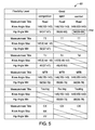
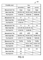
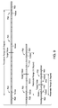
- the parameter range table 62 stores or presets parameter ranges for the knee angle On ("Knee Angle Max” in Figures 5 to 7 ) and the hip angle ⁇ h ("Hip Angle Min” in Figures 5 to 7 ) in association with the flexibility levels (e.g., “Good”, “Fair” and “Stiff” in this embodiment), the bicycle types (e.g., “Road,” “TT,” “Tri,” “MTB” and “CX” in this embodiment), and the riding types (e.g., "competition,” "sport” and “comfort” in this embodiment).
- the controller 12 sets the parameter range for the knee angle ⁇ n according to the parameter range table 62 based on the knee flexibility level of the knee angle ⁇ b ( Figure 2 ), the bicycle type and the riding type.
- the controller 12 also sets the parameter range for the hip angle ⁇ h according to the parameter range table 62 based on the hip flexibility level of the hip angle ⁇ a ( Figure 2 ), the bicycle type and the riding type.
- the computer system 46 prompts the rider or an operator of the bicycle fitting system 10 to input the category information indicative of one of the bicycle types and one of the riding types. In response to receiving the category information, the computer system 46 stores the category information in the memory of the computer system 46.
- the controller 12 acquires the knee flexibility level, the hip flexibility level and the category information from the memory of the computer system 46, and sets the parameter ranges for the knee angle ⁇ n and the hip angle ⁇ h according to the parameter range table 62 based on the knee flexibility level, the hip flexibility level, the bicycle type and the riding type.
- the controller 12 sets the parameter range for the knee angle ⁇ n as a range of 147-137 (degree) with a target value of 142 (degree) (see an encircled portion T11 in Figure 7 ), and the parameter range for the hip angle ⁇ h as a range of 53-63 (degree) with a target value of 58 (degree) (see an encircled portion T12 in Figure 5 ).
- the target values are predetermined as mean values of the parameter ranges, respectively.
- parameter range table 62 indicates the suitable ranges for the knee angle ⁇ n and the hip angle ⁇ h for the rider in view of the flexibility level of the rider body 18, the bicycle type and the riding type of the rider.
- the parameter range table 62 is separately illustrated in Figures 5 to 7 .
- the parameter range table 62 is stored in the memory or hard disc of the computer system 46 as a single table.
- the parameter range table 62 can be stored in the memory or hard disc of the computer system 46 as separate tables.
- the parameter range table 62 can merely store the parameter ranges for the knee angle ⁇ n and the hip angle ⁇ h in association with the flexibility levels and the riding types.
- the parameter range table 62 can merely store the parameter ranges for the knee angle ⁇ n and the hip angle ⁇ h in association with the flexibility levels and the bicycle types.
- the values of the parameter ranges and the target values in the parameter range table 62 shown in Figures 5 to 7 are provided as an example. Thus, the values can be different values.
- no parameter ranges are set for some combinations of the flexibility levels, the bicycle types, and the riding types, which are indicated using diagonal lines in the parameter range table 62.
- the values for some parameter ranges are indicated as "XX" or "YY" in Figures 5 to 7 .
- the controller 12 is further programmed to determine the suitable seat position of the seat 26 and the suitable handlebar position of the handlebar 24.
- the controller 12 is further programmed to determine the suitable seat position and the suitable handlebar position (e.g., a setting position of at least one of a bicycle seat and a bicycle handle) as a bicycle component position of a bicycle component.
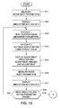
- Figures 10 and 11 are flowcharts of the bicycle fitting process for determining the suitable seat position of the seat 26 and the suitable handlebar position of the handlebar 24.
- the controller 12 acquires the flexibility level of the rider body 18 and the category information indicative of the bicycle type and the riding type in a manner described above.
- the controller 12 measures a set of the rider body parameters of the rider body 18 while the rider rotates the crank assembly 28 ten times (step S11 in Figure 10 ).
- the controller 12 measures the first length 11, the second length 12, the third length 13, the fourth length 14, the fifth length 15, the first deviation s, the second deviation t, the lower leg angle ⁇ 1, the upper leg angle ⁇ 2, the knee angle ⁇ n, the hip angle ⁇ h, the armpit angle ⁇ 4 and the elbow angle ⁇ 5 as the rider body parameters of the rider body 18.
- step S12 the controller 12 determines whether the current rider position of the rider is appropriate based on the flexibility level of the rider body 18 of the rider.
- the controller 12 determines whether the measured knee angle On measured in step S11 falls within the parameter range for the knee angle ⁇ n that has been determined using the parameter range table 62 based on the knee flexibility level of the knee angle ⁇ b ( Figure 2 ), the bicycle type and the riding type.
- the controller 12 also determines whether the measured hip angle ⁇ h measured in step S11 falls within the parameter range for the hip angle ⁇ h that has been determined using the parameter range table 62 based on the hip flexibility level of the hip angle ⁇ a ( Figure 2 ), the bicycle type and the riding type.
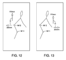
- the controller 12 outputs a bicycle fitting information on the display screen 48 of the computer system 46 (step S12 in Figure 10 ). Specifically, as shown in Figure 12 , the controller 12 output the bicycle fitting information as indicators M11 and M12.
- Figure 12 is a graphical output on the computer system 46.
- the indicators M11 and M12 are displayed at locations corresponding to the LEDs M4 and M5, respectively.
- the indicator M11 indicates whether the measured knee angle ⁇ n falls within the parameter range for the knee angle ⁇ n, while the indicator M12 indicates whether the measured hip angle ⁇ h falls within the parameter range for the hip angle ⁇ h.
- the indicator M11 is displayed in a first color, such as green when the measured knee angle On falls within a center (most suitable) portion P21 of the parameter range for the knee angle ⁇ n.
- the indicator M11 is displayed in a second color, such as yellow when the measured knee angle On falls within edge portions P22 of the parameter range for the knee angle ⁇ n.
- the indicator M11 is displayed in a third color, such as red when the measured knee angle ⁇ n falls outside the parameter range for the knee angle ⁇ n.
- the indicator M12 is displayed in the first color, such as green when the measured hip angle ⁇ h falls within the center portion P21 of the parameter range for the hip angle ⁇ h.
- the indicator M12 is displayed in the second color, such as yellow when the measured hip angle ⁇ h falls within the edge portions P22 of the parameter range for the hip angle ⁇ h.
- the indicator M12 is displayed in the third color, such as red when the measured hip angle ⁇ h falls outside the parameter range for the hip angle ⁇ h.
- the first color, the second color and the third color are different colors, respectively, in the illustrated embodiment.
- the edge portions P22 of the parameter range are set as 1 degree width from the minimum and maximum value of the parameter range, respectively, while the center portion P21 of the parameter range is defined between the edge portions P22 of the parameter range.
- these settings can be different setting as needed and/or desired. Specifically, if the parameter range has 20 degree width, then the center portion P21 is set as a range of ⁇ 9 degree with respect to the target value and the edge portions P22 are set as outside portions of the center portion P21 within the parameter range.
- the center portion P21 is set as a range of ⁇ 4 degree with respect to the target value and the edge portions P22 are set as outside portions of the center portion P21 within the parameter range. Furthermore, if the parameter range has 5 degree width, then the center portion P21 is set as a range of ⁇ 1.5 degree with respect to the target value and the edge portions P22 are set as outside portions of the center portion P21 within the parameter range.
- the controller 12 is further programmed to output the indicators M11 and M12 (e.g., the bicycle fitting information) based on both the rider body parameters and the parameter ranges of the rider body parameters. Furthermore, the indicators M11 and M12 (e.g., the bicycle fitting information) indicate whether the rider body parameters fall within the parameter ranges of the rider body parameters. Moreover, the controller 12 is further programmed to display the indicators M11 and M12 with a first predetermined status (in green or yellow), respectively, in response to the rider body parameters falling within the parameter ranges of the rider body parameters on the display screen 48, respectively.
- a first predetermined status in green or yellow
- the controller 12 is further programmed to display the indicators M11 and M12 with a second predetermined status (in red), respectively, in response to the rider body parameters falling outside the parameter ranges of the rider body parameters on the display screen 48, respectively.
- the second predetermined status is different from the first predetermined status.
- the indicators M11 and M12 are displayed by changing colors to indicate whether the knee angle ⁇ n and the hip angle ⁇ h fall within the parameter ranges, respectively.
- the indicators M11 and M12 can be displayed by changing status of the indicators M11 and M12 to indicate whether the knee angle On and the hip angle ⁇ h fall within the parameter ranges, respectively.
- the indicators M11 and M12 can be displayed by changing shape, brightness, line-style or dash-style of the indicators M11 and M12, or by flashing on and off the indicators M11 and M12 to indicate whether the knee angle ⁇ n and the hip angle ⁇ h fall within the parameter ranges, respectively.
- the indicators M11 and M12 are displayed in green, yellow or red.
- the indicators M11 and M12 can be displayed in only two colors, or in more than three colors according to the determination result.
- the controller 12 calculates the position (X2, Y2) of the seat 26 (the LED M5) with respect to the position (X0, Y0) of the LED M3 using the measured rider body parameters of the rider body 18, such as the first length 11, the second length 12, the first deviation s, the second deviation t, the lower leg angle ⁇ 1, the upper leg angle ⁇ 2, the knee angle ⁇ n, for example.
- the position (X2, Y2) of the seat 26 with respect to the position (X0, Y0) of the LED M3 is calculated based on Equations (18) and (19) below using measured rider body parameters of the rider body 18 measured in step S11 (or S16).
- the position (X0, Y0) of the LED M3 is used as a reference position to calculate the relative position (X2, Y2) of the seat 26.
- the position (X0, Y0) of the LED M3 can be set as (0, 0).
- the calculated position (X2, Y2) that is calculated for the first time after starting the bicycle fitting process is stored in the memory of the computer system 46 as an initial seat position.
- the controller 12 determines the suitable seat position (X2, Y2) of the seat 26 using the target value for the knee angle ⁇ n (step S 14 in Figure 10 ).
- the target value for the knee angle ⁇ n has been determined using the parameter range table 62 based on the knee flexibility level of the knee angle ⁇ b ( Figure 2 ), the bicycle type and the riding type.
- the seat position (X2, Y2) is expressed using the first length 11, the second length 12, the lower leg angle ⁇ 1 and the upper leg angle ⁇ 2 according to the following Equations (1) and (2).
- X 2 X 0 + l 1 ⁇ cos ⁇ 1 + l 2 ⁇ cos ⁇ 2
- Y 2 Y 0 + l 1 ⁇ sin ⁇ 1 + l 2 ⁇ sin ⁇ 2
- (X0, Y0) indicates the position of the LED 3 when the crank arm 38 of the crank assembly 28 is vertically oriented at the bottom dead center.
- the position (X0, Y0) of the LED 3 is used as a reference for the determination of the suitable seat position (X2, Y2).
- ⁇ n ⁇ 1 + 180 - ⁇ 2
- the seat position (X2, Y2) can also be expressed according to the following Equations (4) and (5).
- X 2 X 0 ⁇ ⁇ + l 1 ⁇ cos ⁇ 1 ⁇ ⁇ + l 2 ⁇ cos ⁇ 2 ⁇ ⁇
- Y 2 Y 0 ⁇ ⁇ + l 1 ⁇ sin ⁇ 1 ⁇ ⁇ + l 2 ⁇ sin ⁇ 2 ⁇ ⁇
- (X0', Y0') indicates the position of the LED 3 when the crank arm 38 of the crank assembly 28 is horizontally oriented and forwardly extends from the crank axle 42 in the horizontal direction X.
- a lower leg angle ⁇ 1' is defined as an angle at the LED M3 enclosed by the horizontal line extending through the LED M3 and the line from the LED M3 to the LED M4 when the crank arm 38 of the crank assembly 28 is horizontally oriented and forwardly extends from the crank axle 42 in the horizontal direction X.
- an upper leg angle ⁇ 2' is defined as an angle at the LED M4 enclosed by the horizontal line extending through the LED M4 and the line from the LED M4 to the LED M5 when the crank arm 38 of the crank assembly 28 is horizontally oriented and forwardly extends from the crank axle 42 in the horizontal direction X.
- Equation (6) the relationship expressed by the following Equation (6) is established using the first deviation s and the second deviation t.
- X 0 ⁇ ⁇ + t + s X 0 ⁇ ⁇ + l 1 ⁇ cos ⁇ 1 ⁇ ⁇
- Equation (6) the lower leg angle ⁇ 1' can be calculated based on Equation (6) as expressed in the following Equation (7).
- Equation (7) the lower leg angle ⁇ 1' can be calculated based on Equation (6) as expressed in the following Equation (7).
- r is a crank arm length of the crank arm 38 measured or defined between the center axis of the crank axle 42 (e.g., a crank axis) and a pedal axis of the pedal 40.
- Equation (9) the relationships expressed by the following Equations (10) and (11) are established.
- Equation (9) the relationships expressed by the following Equations (10) and (11) are established.
- Equation (4) Based on Equation (4), the relationship expressed by the following Equations are established.
- Equation (5) the relationships expressed by the following Equations are established.
- Equation (14) By adding Equation (14) to Equation (13), and by setting (r + 11cos ⁇ 1') as A and (r + 11sin ⁇ 1') as B, the relationships expressed by the following Equations (15) and (16) are established.
- a 2 + B 2 + l 2 2 + 2 ⁇ l 2 ⁇ Acos ⁇ ⁇ 2 ⁇ ⁇ + Bsin ⁇ ⁇ 2 ⁇ ⁇ X 2 - X 0 2 + Y 2 - Y 0 2
- a B X 2 - X 0 2 + Y 2 - Y 0 2
- the lower leg angle ⁇ 1' can also be calculated.
- the seat position (X2, Y2) can be calculated by the following Equations (18) and (19).
- the controller 12 calculates the suitable seat position (X2, Y2) based on the above-mentioned Equations (18) and (19). Specifically, the controller 12 calculates the lower leg angle ⁇ 1' based on Equation (7) using the first deviation s, the second deviation t, and the first length 11. In the illustrated embodiment, the controller 12 calculates the lower leg angle ⁇ 1' based on Equation (7) using the measured values of the second deviation t and first length 11 that have been measured as explained above, and a preset value of the first deviation s.
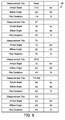
- the computer system 46 stores a preset parameter table 64 for presetting preset parameters of the armpit angle ⁇ 4, the elbow angle ⁇ 5 and the first deviation s in a memory or hard disc (not shown) of the computer system 46.
- the preset parameter table 64 stores or presets the preset parameters for the armpit angle ⁇ 4, the elbow angle ⁇ 5 and the first deviation s in association with the bicycle types (e.g., "Road,” “TT,” “Tri,” “MTB” and "CX" in this embodiment).
- the controller 12 sets the preset parameters for the armpit angle ⁇ 4, the elbow angle ⁇ 5 and the first deviation s based on the bicycle type of the category information inputted by the rider or the operator of the bicycle fitting system 10 to the computer system 46.
- the controller 12 calculates Equation (7) using the preset value of the first deviation s.
- the controller 12 can calculate Equation (7) using a measured value of the first deviation s.
- some of the preset parameters are indicated as "XX". Although the specific values of the "XX" are not described in the illustrated embodiment, it will be apparent to those skilled in the art from this disclosure that these thresholds can be experimentally predetermined.
- the controller 12 further calculates the upper leg angle ⁇ 2' based on Equation (17) using the first length 11, the second length 12, the crank arm length r, the lower leg angle ⁇ 1' and the knee angle ⁇ n.
- the controller 12 calculates the upper leg angle ⁇ 2' based on Equation (17) using the measured values of the first length 11 and the second length 12 that have been measured as explained above, the preset value of the crank arm length r, the calculated value of the lower leg angle ⁇ 1' that has been calculated based on Equation (7), and the preset target value of the knee angle ⁇ n.
- the preset target value of the knee angle ⁇ n is determined based on the parameter range table 62 shown in Figures 5 to 7 according to the knee flexibility level, the bicycle type and the riding type (i.e., the flexibility level of the rider body 18 and the category information).
- the controller 12 further calculates the suitable seat position (X2, Y2) based on the above-mentioned Equations (18) and (19) using the position (X0, Y0) of the LED M3, the crank arm length r, the first length 11, the second length 12, the lower leg angle ⁇ 1' and the upper leg angle ⁇ 2'.
- the controller 12 calculates the seat position (X2, Y2) based on the above-mentioned Equations (18) and (19) using the measured values of the first length 11 and the second length 12 that have been measured as explained above, the preset value of the crank arm length r, and the calculated values of the lower leg angle ⁇ 1' and the upper leg angle ⁇ 2' that have been calculated based on Equations (7) and (17).
- the position (X0, Y0) of the LED M3 is used as a reference position to calculate the suitable seat position (X2, Y2) of the seat 26.
- the position (X0, Y0) of the LED M3 can be set as (0, 0).
- the controller 12 outputs adjustment directions of the seat 26 and adjustment amounts of the seat 26 on the display screen 48 of the computer system 46 (step S15 in Figure 10 ). Specifically, the controller 12 is further programmed to determine the adjustment directions of the seat 26 (e.g., the bicycle component) and the adjustment amounts of the seat 26 (e.g., the bicycle component) based on the suitable seat position (X2, Y2) (e.g., the bicycle component position). Specifically, in the illustrated embodiment, the controller 12 calculates the deviation between the position (X2, Y2) of the seat 26 calculated in step S13 and the suitable seat position (X2, Y2) of the seat 26 calculated in step S14.
- the controller 12 calculates the deviation between the position (X2, Y2) of the seat 26 calculated in step S13 and the suitable seat position (X2, Y2) of the seat 26 calculated in step S14.
- the controller 12 subtract the position (X2, Y2) of the seat 26 calculated in step S13 from the suitable seat position (X2, Y2) of the seat 26 calculated in step S 14 to obtain the adjustment directions of the seat 26 and the adjustment amounts of the seat 26 in the horizontal direction X and in the vertical direction Y. Then, as shown in Figure 12 , the controller 12 displays arrows R indicative of the adjustment directions of the seat 26 together with the adjustment amounts of the seat 26. In other words, the controller 12 is further programmed to output the adjustment directions and the adjustment amounts on the display screen 48 (e.g., the output apparatus).
- the indicators M11 and M12, the adjustment directions and the adjustment amounts are displayed in the same display image as shown in Figure 12 . However, alternatively, the indicators M11 and M12, the adjustment directions and the adjustment amounts can be displayed in different display images, respectively.
- the rider or the operator of the bicycle fitting system 10 adjusts the seat 26 with respect to the frame 22 according to the graphic image displayed on the display screen 48. While adjusting the seat 26 with respect to the frame 22, the bicycle fitting equipment 16 can output the adjustment data indicative of the actual seat adjustment amounts to the controller 12 in the horizontal direction X and in the vertical direction Y as ( ⁇ x1, ⁇ y1). The controller 12 further outputs the adjustment directions of the seat 26 and the adjustment amounts of the seat 26 according to the seat adjustment amounts ( ⁇ x1, ⁇ y1) from the bicycle fitting equipment 16.
- the controller 12 measures the set of the rider body parameters of the rider body 18 while the rider rotates the crank assembly 28 ten times in the same manner as step S11 (step S 16 in Figure 10 ).
- step S 17 the controller 12 determines whether the measured knee angle ⁇ n measured in step S16 falls within the parameter range for the knee angle ⁇ n in the same manner as step S12. Furthermore, the controller 12 also determines whether the measured hip angle ⁇ h measured in step S16 falls within the parameter range for the hip angle ⁇ h in the same manner as step S12. Then, the controller 12 outputs the bicycle fitting information (i.e., the indicators M11 and M12) on the display screen 48 of the computer system 46 shown in Figure 12 in the same manner as step S12.
- the bicycle fitting information i.e., the indicators M11 and M12
- step S16 determines that the measured knee angle ⁇ n measured in step S16 falls outside the parameter range for the knee angle ⁇ n in the same manner as step S12 ("No" in step S18), then the process returns to step S13.
- the indicator M11 on the display screen 48 is displayed in red
- the processes from step S13 to S18 are repeated until the indicator M11 is displayed in green or yellow.
- the suitable seat position (X2, Y2) of the seat 26 calculated in step S14 will be updated as a temporal bicycle component position while the measured knee angle ⁇ n measured in step S11 or step S16 falls outside the parameter range for the knee angle ⁇ n.
- the controller 12 is further programmed to determine the temporal bicycle component position of the seat 26 (e.g., the bicycle component) based on the rider body parameters in response to measured knee angle ⁇ n (e.g., the one of the rider body parameters) falling outside the parameter range of the measured knee angle On (e.g., the one of the rider body parameters). Then, the bicycle fitting equipment 16 is adjusted based on the temporal bicycle component position in step S 17. On the other hand, if the controller 12 determines that the measured knee angle On measured in step S16 falls within the parameter range for the knee angle ⁇ n in the same manner as step S12 ("Yes" in step S18), then the process proceeds to step S21 in Figure 11 . In other words, when the indicator M11 on the display screen 48 is displayed in green or yellow, the adjustment of the seat 26 is completed.
- ⁇ n e.g., the one of the rider body parameters
- the bicycle fitting equipment 16 is adjusted based on the temporal bicycle component position in step S 17.
- the controller 12 determines that the
- the controller 12 calculates the position (X3, Y3) of the handlebar 24 (the LED M8) with respect to the position (X0, Y0) of the LED M3 using the measured rider body parameters of the rider body 18 measured in step S16, such as the first to fifth lengths 11 to 15, the first deviation s, the second deviation t, the knee angle ⁇ n, the hip angle ⁇ h, the armpit angle ⁇ 4, and the elbow angle ⁇ 5 for example.
- the position (X3, Y3) of the handlebar 24 with respect to the position (X0, Y0) of the LED M3 is calculated based on Equations (26) and (27) below using measured rider body parameters of the rider body 18 measured in step S16 (or S24). Equations (26) and (27) will be described in detail later.
- the position (X0, Y0) of the LED M3 is used as a reference position to calculate the relative position (X3, Y3) of the handlebar 24.
- the position (X0, Y0) of the LED M3 can be set as (0, 0).
- the calculated position (X3, Y3) that is calculated for the first time after starting the bicycle fitting process is stored in the memory of the computer system 46 as an initial handlebar position.
- the controller 12 determines the suitable handlebar position (X3, Y3) of the handlebar 24 using the target value for the hip angle ⁇ h (step S22 in Figure 11 ).
- the target value for the hip angle ⁇ h has been determined using the parameter range table 62 based on the hip flexibility level of the hip angle ⁇ a ( Figure 2 ), the bicycle type and the riding type.
- the knee angle ⁇ n2 is defined as an angle at the LED M4 enclosed by the lines from the LED M4 to the LED M5 and the LED M4 to the LED M3 when the crank arm 38 of the crank assembly 28 is vertically oriented at the top dead center.
- (X0", Y0") indicates the position of the LED M3 when the crank arm 38 of the crank assembly 28
- the relationships expressed by the following Equations are established.
- the angle ⁇ is defined as an angle at the LED M3 enclosed by the lines from the LED M3 to the LED M4 and the LED M3 to the LED M5 when the crank arm 38 of the crank assembly 28 is vertically oriented at the top dead center.
- the lower leg angle ⁇ 1 is defined as an angle at the LED M3 enclosed by the horizontal line extending through the LED M3 and the line from the LED M3 to the LED M4 when the crank arm 38 of the crank assembly 28 is vertically oriented at the top dead center.
- Equations (24) and (25) are established.
- the upper leg angle ⁇ 2" is defined as an angle at the LED M4 enclosed by the horizontal line extending through the LED M4 and the line from the LED M4 to the LED M5 when the crank arm 38 of the crank assembly 28 is vertically oriented at the top dead center.
- the back angle ⁇ back is defined as an angle at the LED M5 enclosed by the horizontal line extending through the LED M5 and the line from the LED M5 to the LED M6.
- the handlebar position (X3, Y3) can be calculated by the following Equations (26) and (27).
- X 3 X 2 + l 3 ⁇ cos ⁇ back + l 4 ⁇ cos 180 - ⁇ back - ⁇ 4 + l 5 ⁇ cos ⁇ 5 - 180 - 180 - ⁇ back - ⁇ 4
- Y 3 Y 2 + l 3 ⁇ sin ⁇ back + l 4 ⁇ sin 180 - ⁇ back - ⁇ 4 + l 5 ⁇ sin ⁇ 5 - 180 - 180 - ⁇ back - ⁇ 4
- the controller 12 calculates the suitable handlebar position (X3, Y3) based on the above-mentioned Equations (26) and (27). Specifically, the controller 12 calculates the lower leg angle ⁇ 1 based on Equation (23) using the seat position (X2, Y2), the first length 11, the second length 12, the crank arm length r. In the illustrated embodiment, the controller 12 calculates the lower leg angle ⁇ 1" based on Equation (23) using the measured values of the first length 11 and the second length 12 that have been measured as explained above, and the preset value of the crank arm length r. Furthermore, the controller 12 calculates the lower leg angle ⁇ 1" based on Equation (23) using the seat position (X2, Y2) calculated in step S14.
- the controller 12 calculates the upper leg angle ⁇ 2" based on Equation (24) using the calculated lower leg angle ⁇ 1", and the knee angle ⁇ n2 calculated based on Equation (20). Furthermore, the controller 12 calculates the back angle ⁇ back based on Equation (25) using the calculated upper leg angle ⁇ 2" and the hip angle ⁇ h. Specifically, the controller 12 calculates the back angle ⁇ back based on Equation (25) using the preset target value of the hip angle ⁇ h.
- the preset target value of the hip angle ⁇ h is determined based on the parameter range table 62 shown in Figures 5 to 7 according to the hip flexibility level, the bicycle type and the riding type (i.e., the flexibility level of the rider body 18 and the category information).
- the controller 12 further calculates the suitable handlebar position (X3, Y3) based on the above-mentioned Equations (26) and (27) using the position (X2, Y2) of the seat 26 calculated in step S 14, the third length 13, the fourth length 14, the fifth length 15, the armpit angle ⁇ 4, the elbow angle ⁇ 5, and the back angle ⁇ back .
- the controller 12 calculates the handlebar position (X3, Y3) based on the above-mentioned Equations (26) and (27) using the measured values of the third to fifth lengths 13 to 15 that have been measured as explained above, the calculated value of the back angle ⁇ back that has been calculated as mentioned above, and preset values of the armpit angle ⁇ 4 and the elbow angle ⁇ 5.
- the controller 12 sets the preset parameters for the armpit angle ⁇ 4, the elbow angle ⁇ 5 and the first deviation s using the preset parameter table 64 shown in Figure 8 based on the bicycle type of the category information inputted by the rider or the operator of the bicycle fitting system 10 to the computer system 46.
- the controller 12 calculates Equations (26) and (27) using the preset values of the armpit angle ⁇ 4 and the elbow angle ⁇ 5.
- the controller 12 can calculate Equation (26) and (27) using measured values of the armpit angle ⁇ 4 and the elbow angle ⁇ 5.
- the position (X0, Y0) of the LED M3 is used as a reference position to calculate the suitable handlebar position (X3, Y3) of the handlebar 24.
- the position (X0, Y0) of the LED M3 can be set as (0, 0).
- the controller 12 outputs adjustment directions of the handlebar 24 and adjustment amounts of the handlebar 24 on the display screen 48 of the computer system 46 (step S23 in Figure 11 ). Specifically, the controller 12 is further programmed to determine the adjustment directions of the handlebar 24 (e.g., the bicycle component) and the adjustment amounts of the handlebar 24 (e.g., the bicycle component) based on the suitable handlebar position (X3, Y3) (e.g., the bicycle component position). Specifically, in the illustrated embodiment, the controller 12 calculates the deviation between the position (X3, Y3) of the handlebar 24 calculated in step S21 and the suitable handlebar position (X3, Y3) of the handlebar 24 calculated in step S22.
- the controller 12 calculates the deviation between the position (X3, Y3) of the handlebar 24 calculated in step S21 and the suitable handlebar position (X3, Y3) of the handlebar 24 calculated in step S22.
- the controller 12 subtract the position (X3, Y3) of the handlebar 24 calculated in step S21 from the suitable handlebar position (X3, Y3) of the handlebar 24 calculated in step S 22 to obtain the adjustment directions of the handlebar 24 and the adjustment amounts of the handlebar 24 in the horizontal direction X and in the vertical direction Y. Then, as shown in Figure 13 , the controller 12 displays arrows R indicative of the adjustment directions of the handlebar 24 together with the adjustment amounts of the handlebar 24. In other words, the controller 12 is further programmed to output the adjustment directions and the adjustment amounts on the display screen 48 (e.g., the output apparatus).
- the indicators M11 and M12, the adjustment directions and the adjustment amounts are displayed in the same display image as shown in Figure 13 . However, alternatively, the indicators M11 and M12, the adjustment directions and the adjustment amounts can be displayed in different display images, respectively.
- the rider or the operator of the bicycle fitting system 10 adjusts the handlebar 24 with respect to the frame 22 according to the graphic image displayed on the display screen 48. While adjusting the handlebar 24 with respect to the frame 22, the bicycle fitting equipment 16 can output the adjustment data indicative of the actual handlebar adjustment amounts to the controller 12 in the horizontal direction X and in the vertical direction Y as ( ⁇ x2, ⁇ y2). The controller 12 further outputs the adjustment directions of the handlebar 24 and the adjustment amounts of the handlebar 24 according to the handlebar adjustment amounts ( ⁇ x2, ⁇ y2) from the bicycle fitting equipment 16.
- the controller 12 measures the set of the rider body parameters of the rider body 18 while the rider rotates the crank assembly 28 ten times in the same manner as step S11 (step S24 in Figure 11 ).
- step S25 the controller 12 determines whether the measured knee angle ⁇ n measured in step S24 falls within the parameter range for the knee angle ⁇ n in the same manner as step S 12. Furthermore, the controller 12 also determines whether the measured hip angle ⁇ h measured in step S24 falls within the parameter range for the hip angle ⁇ h in the same manner as step S12. Then, the controller 12 outputs the bicycle fitting information (i.e., the indicators M11 and M12) on the display screen 48 of the computer system 46 shown in Figure 13 in the same manner as step S12.
- the bicycle fitting information i.e., the indicators M11 and M12
- step S24 determines that the measured hip angle ⁇ h measured in step S24 falls outside the parameter range for the hip angle ⁇ h in the same manner as step S12 ("No" in step S26), then the process returns to step S21.
- the suitable handlebar position (X3, Y3) of the handlebar 24 calculated in step S22 will be updated as a temporal bicycle component position while the measured hip angle ⁇ h measured in step S 16 or step S24 falls outside the parameter range for the hip angle ⁇ h.
- the controller 12 is further programmed to determine the temporal bicycle component position of the handlebar 24 (e.g., the bicycle component) based on the rider body parameters in response to measured hip angle ⁇ h (e.g., the one of the rider body parameters) falling outside the parameter range of the measured hip angle ⁇ h (e.g., the one of the rider body parameters). Then, the bicycle fitting equipment 16 is adjusted based on the temporal bicycle component position in step S25. On the other hand, if the controller 12 determines that the measured hip angle ⁇ h measured in step S24 falls within the parameter range for the hip angle ⁇ h in the same manner as step S12 ("Yes" in step S26), then the bicycle fitting process is completed. In other words, when the indicator M12 on the display screen 48 is displayed in green or yellow, the adjustment of the handlebar 24 is completed.
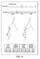
- the controller 12 After determining the suitable seat position (X2, Y2) and the suitable handlebar position (X3, Y3), the controller 12 output the bicycle fitting information on the display screen 48.
- the controller 12 output the bicycle fitting information as shown in Figure 14 in response to the rider or the operator of the bicycle fitting system 10 pressing a finish button provided by the bicycle fitting software.
- the controller 12 can automatically output the bicycle fitting information as shown in Figure 14 in response to the controller 12 determining that the measured hip angle ⁇ h measured in step S24 falls within the parameter range for the hip angle ⁇ h in step S26.
- the controller 12 graphically displays the measured flexibility levels (i.e., the knee flexibility level "knee angle", and the hip flexibility level "hip angle”) as the bicycle fitting information.
- the controller 12 also graphically displays the initial body parameters and the adjusted body parameters as the bicycle fitting information.
- the controller 12 outputs a graphic image showing the initial value of the knee angle On ("120 degree” in Figure 14 ) and the initial value of the hip angle ⁇ h ("30 degree” in Figure 14 ) that are measured in step S11 in Figure 10 .
- the controller 12 also outputs a graphic image showing the adjusted value of the knee angle ⁇ n ("140 degree” in Figure 14 ) and the adjusted value of the hip angle ⁇ h (“50 degree” in Figure 14 ) that are measured in step S24 in Figure 11 for the last time.
- the controller 12 graphically displays the initial seat position (X2, Y2), the initial handlebar position (X3, Y3), the suitable seat position (X2, Y2), and the suitable handlebar position (X3, Y3) on the orthogonal coordinate system with the axes extending in the horizontal direction X and in the vertical direction Y, respectively, as the bicycle fitting information to reflect the positions to the user's bicycle.
- the orthogonal coordinate system has the origin at the center axis of the crank axle 42.
- One parameter Y indicates the vertical position, while the other parameter X indicates the horizontal portion.
- the controller 12 is further programmed to output the suitable seat position (X2, Y2) and the suitable handlebar position (X3, Y3) (e.g., the bicycle fitting information) based on the knee angle On and the hip angle On (e.g., the rider body parameters), and the parameter ranges of the knee angle ⁇ n and the hip angle ⁇ n (e.g., the rider body parameters).
- the suitable seat position (X2, Y2) and the suitable handlebar position (X3, Y3) indicates the bicycle component positions of the bicycle component.
- the controller 12 is further programmed to output the suitable seat position (X2, Y2) and the suitable handlebar position (X3, Y3) (e.g., the bicycle component positions) on the display screen (e.g., the output apparatus).
- the controller 12 is further programmed to acquire the initial seat position (X2, Y2) of the seat 26 and the initial handlebar position (X3, Y3) of the handlebar (e.g., the initial bicycle component positions of the bicycle components).
- the controller 12 is further programmed to output the suitable seat position (X2, Y2) and the suitable handlebar position (X3, Y3) (e.g., the bicycle component positions), and the initial seat position (X2, Y2) and the initial handlebar position (X3, Y3) (e.g., the initial bicycle component positions).
- the controller 12 outputs a graphic image showing the initial seat position (X2, Y2) that is calculated in step S 13 in Figure 10 for the first time, and the initial handlebar position (X3, Y3) that is calculated in step S21 in Figure 11 for the first time.
- the controller 12 also outputs a graphic image showing the suitable seat position (X2, Y2) that is calculated in step S 14 in Figure 10 for the last time, and the suitable handlebar position (X3, Y3) that is calculated in step S22 in Figure 11 for the last time.
- the initial seat position (X2, Y2), the initial handlebar position (X3, Y3), the suitable seat position (X2, Y2), and the suitable handlebar position (X3, Y3) are output as positions relative to the center axis of the crank axle 42.
- the controller 12 saves the calculation results in a CSV file and the like.
- the controller 12 outputs the bicycle fitting information shown in Figures 12 to 14 on the display screen 48. However, alternatively or additionally, the controller 12 can print the bicycle fitting information shown in Figures 12 to 14 on a sheet through a printer device.
- Coupled encompasses configurations in which an element is directly secured to another element by affixing the element directly to the other element; configurations in which the element is indirectly secured to the other element by affixing the element to the intermediate member(s) which in turn are affixed to the other element; and configurations in which one element is integral with another element, i.e. one element is essentially part of the other element.
- This definition also applies to words of similar meaning, for example, “joined”, “connected”, “attached”, “mounted”, “bonded”, “fixed” and their derivatives.
- first and second may be used herein to describe various components these components should not be limited by these terms. These terms are only used to distinguish one component from another. Thus, for example, a first component discussed above could be termed a second component and vice-a-versa without departing from the teachings of the present invention. Also, the terms “part,” “section,” “portion,” “member” or “element” when used in the singular can have the dual meaning of a single part or a plurality of parts. Finally, terms of degree such as “substantially”, “about” and “approximately” as used herein mean an amount of deviation of the modified term such that the end result is not significantly changed.
Landscapes
- Health & Medical Sciences (AREA)
- Life Sciences & Earth Sciences (AREA)
- General Health & Medical Sciences (AREA)
- Engineering & Computer Science (AREA)
- Physical Education & Sports Medicine (AREA)
- Oral & Maxillofacial Surgery (AREA)
- Molecular Biology (AREA)
- Dentistry (AREA)
- Biophysics (AREA)
- Pathology (AREA)
- Physiology (AREA)
- Biomedical Technology (AREA)
- Heart & Thoracic Surgery (AREA)
- Medical Informatics (AREA)
- Physics & Mathematics (AREA)
- Surgery (AREA)
- Animal Behavior & Ethology (AREA)
- Public Health (AREA)
- Veterinary Medicine (AREA)
- Mechanical Engineering (AREA)
- Length Measuring Devices With Unspecified Measuring Means (AREA)
- Length Measuring Devices By Optical Means (AREA)
Abstract
Description
- This application claims priority to
U.S. Patent Application No. 13/968,435 , filed on August 16, 2013. The entire disclosure ofU.S. Patent Application No. 13/968,435 is hereby incorporated herein by reference. - The present invention generally relates to a bicycle fitting system. In particular, the present invention relates to a bicycle fitting system for a bicycle fitting.
- Conventional bicycle fitting systems measures rider body sizes of a rider, and adjusts bicycle components of a bicycle based on the rider body sizes. For example, a conventional bicycle fitting system utilizes a three-dimensional marker tracking system that detects markers attached to a rider body for measuring rider body sizes of the rider (see
U.S. Patent Application Publication No. 2007/0142177 A1 , for example). - For the sake of rider's comfort and cycling performance while riding the bicycle, the bicycle components need to be properly adjusted for obtaining a suitable riding posture for the rider. However, it has been discovered that it is difficult to find a suitable riding posture of a rider since the suitable riding posture varies according to rider body characteristics, bicycle types, riding types or the like.
- One object of the disclosure is to provide a bicycle fitting system with which a suitable position of a bicycle component can be obtained for each rider.
- In accordance with a first aspect, a bicycle fitting system includes a controller programmed to determine whether a current rider position of a rider is appropriate based on a flexibility level of a rider body of the rider.
- Preferably, the bicycle fitting system further includes a motion capturing apparatus electrically connected to the controller. The controller is further programmed to determine the flexibility level using the motion capturing apparatus.
- Preferably, the controller is programmed to measure a plurality of rider body parameters of the rider body using the motion capturing apparatus while the rider is on a bicycle fitting equipment.
- Preferably, the controller is programmed to set a parameter range of one of the rider body parameters based on the flexibility level, and output a bicycle fitting information based on both the rider body parameters and the parameter range of the one of the rider body parameters.
- Preferably, the bicycle fitting information indicates a bicycle component position of a bicycle component.
- Preferably, the bicycle fitting information indicates whether the one of the rider body parameters falls within the parameter range of the one of the rider body parameters.
- Preferably, the controller is programmed to acquire category information indicative of at least one of a bicycle type and a riding type, and to set the parameter range of the one of the rider body parameters based on the flexibility level and the category information.
- Preferably, the controller is programmed to determine a setting position of at least one of a bicycle seat and a bicycle handle as the bicycle component position.
- The controller is programmed to determine a temporal bicycle component position of a bicycle component based on the rider body parameters in response to the one of the rider body parameters falling outside the parameter range of the one of the rider body parameters. The bicycle fitting equipment is adjusted based on the temporal bicycle component position.
- Preferably the controller is programmed to output the bicycle component position on an output apparatus.
- The controller is programmed to acquire an initial bicycle component position of the bicycle component. The controller is preferably programmed to output the bicycle component position and the initial bicycle component position.
- Preferably, the controller is programmed to determine an adjustment direction of the bicycle component and an adjustment amount of the bicycle component based on the bicycle component position. The controller is preferably programmed to output the adjustment direction and the adjustment amount on an output apparatus.
- Preferably, the controller is programmed to display an indicator with a first predetermined status in response to the one of the rider body parameters falling within the parameter range of the one of the rider body parameters on a display screen. The controller is preferably programmed to display the indicator with a second predetermined status in response to the one of the rider body parameters falling outside the parameter range of the one of the rider body parameters on the display screen. The second predetermined status is different from the first predetermined status.
- Referring now to the attached drawings which form a part of this original disclosure:
-
Figure 1 is a schematic view of a bicycle fitting system in accordance with a first embodiment, illustrating a rider riding on a bicycle fitting equipment while a motion capturing apparatus detects LEDs attached to a rider body of the rider; -
Figure 2 is a schematic diagram illustrating measurements of flexibility levels of the rider body of the rider; -
Figure 3 is a schematic diagram illustrating rider body parameters of the rider body with respect to a crank assembly of the bicycle fitting stand; -
Figure 4 is a schematic diagram illustrating rider body parameters of the rider body with respect to the crank assembly of the bicycle fitting stand; -
Figure 5 is a schematic diagram of a part of a parameter range table storing parameter ranges of the rider body parameters in association with the flexibility levels, bicycle types, and riding types; -
Figure 6 is a schematic diagram of another part of the parameter range table storing the parameter ranges of the rider body parameters in association with the flexibility levels, the bicycle types, and the riding types; -
Figure 7 is a schematic diagram of yet another part of the parameter range table storing the parameter ranges of the rider body parameters in association with the flexibility levels, the bicycle types, and the riding types; -
Figure 8 is a schematic diagram of a preset parameter table storing predetermined values of the rider body parameters in association with the bicycle types; -
Figure 9 is a schematic diagram illustrating determination of an indicator status of an indicator indicative of a status of a current rider position; -
Figure 10 is a flowchart of a suitable seat position calculation of a bicycle fitting method in accordance with the first embodiment; -
Figure 11 is a flowchart of a suitable handlebar position calculation of the bicycle fitting method in accordance with the first embodiment; -
Figure 12 is a schematic diagram of an display image displayed on a display screen, the display image showing an adjustment direction of the seat position and an adjustment amount of the seat position; -
Figure 13 is a schematic diagram of an display image displayed on the display screen, the display image showing an adjustment direction of the handlebar position and an adjustment amount of the handlebar position; and -
Figure 14 is a schematic diagram of a display image displayed on the display screen, the display image showing a bicycle fitting result. - Selected embodiments will now be explained with reference to the drawings. It will be apparent to those skilled in the art from this disclosure that the following descriptions of the embodiments are provided for illustration only and not for the purpose of limiting the invention as defined by the appended claims and their equivalents.
- Referring initially to
Figure 1 , abicycle fitting system 10 is illustrated in accordance with a first embodiment. As illustrated inFigure 1 , thebicycle fitting system 10 includes acontroller 12. Thebicycle fitting system 10 also includes amotion capturing apparatus 14 electrically connected to thecontroller 12. In the illustrated embodiment, thebicycle fitting system 10 determines whether a current rider position of a rider is appropriate while the rider is riding on abicycle fitting equipment 16. Specifically, with thebicycle fitting system 10, thecontroller 12 is programmed to measure a plurality of rider body parameters of arider body 18 using themotion capturing apparatus 14 while the rider is on thebicycle fitting equipment 16. Furthermore, thecontroller 12 is further programmed to determine bicycle component positions of bicycle components. In the illustrated embodiment, thecontroller 12 determines a suitable seat position and a suitable handlebar position. However, thecontroller 12 can also be configured to determine bicycle component positions other than the suitable seat position and the suitable handlebar position. The configurations of thecontroller 12 will be explained later in detail. - The
bicycle fitting equipment 16 is equipment that makes it possible to simulate a bicycle riding while remaining stationary. Thebicycle fitting equipment 16 includes a stand orframe 22, a handlebar 24 (e.g., a bicycle handle), a seat or saddle 26 (e.g., a bicycle seat), acrank assembly 28, arear wheel 30 and aresistance unit 32. Thehandlebar 24 and theseat 26 are adjustably coupled to theframe 22 in a conventional manner. Thehandlebar 24 and theseat 26 are adjustable with respect to theframe 22 in a horizontal direction X and in a vertical direction Y perpendicular to the horizontal direction X. Specifically, in the illustrated embodiment, thehandlebar 24 is adjustably supported to theframe 22 by anadjustable handlebar support 34. Theadjustable handlebar support 34 is operatively disposed between theframe 22 and thehandlebar 24. Theadjustable handlebar support 34 has a horizontal part horizontally slidable with respect to theframe 22, and a vertical part vertically slidable with respect to the horizontal part. Theseat 26 is also adjustably supported by anadjustable seat support 36 in the horizontal direction X and in the vertical direction Y. In the illustrated embodiment, thehandlebar 24 and theseat 26 are manually adjustable with respect to theframe 22. Specifically, theadjustable handlebar support 34 has scales indicative of current handlebar positions in the horizontal direction X and in the vertical direction Y, respectively, with respect to a reference position or origin of theframe 22. Also, theadjustable seat support 36 has scales indicative of current seat positions in the horizontal direction X and in the vertical direction Y, respectively, with respect to the reference position or origin of theframe 22. As mentioned above, in the illustrated embodiment, thehandlebar 24 and theseat 26 are manually adjustable with respect to theframe 22. However, of course, the bicyclefitting equipment 16 can include an electrical drive unit for automatically and electrically adjusting thehandlebar 24 and theseat 26 in the horizontal direction X and the vertical direction Y. Furthermore, the bicyclefitting equipment 16 can be electrically connected to thecontroller 12 to output adjustment data indicative of handlebar adjustment amounts in the horizontal direction X and in the vertical direction Y, and adjustment data indicative of seat adjustment amounts in the horizontal direction X and in the vertical direction Y. In particular, in this case, theadjustable handlebar support 34 has sensors to detect the handlebar adjustment amounts of thehandlebar 24 with respect to theframe 22 in the horizontal direction X and in the vertical direction Y, and outputs the adjustment data indicative of the handlebar adjustment amounts to thecontroller 12. On the other hand, theadjustable seat support 36 has sensors to detect the seat adjustment amounts of theseat 26 with respect to theframe 22 in the horizontal direction X and in the vertical direction Y, and outputs the adjustment data indicative of the seat adjustment amounts to thecontroller 12. - The
crank assembly 28 is rotatably supported to theframe 22 by a bottom bracket part. Thecrank assembly 28 has a pair of crankarms 38. Each of thecrank arms 38 includes a pedal 40 that is mounted to the free end of a respective one of thecrank arms 38. The crankarms 38 have inner ends fixed to opposite ends acrank axle 42, with the crankarms 38 extending in opposite radial directions from thecrank axle 42. In the illustrated embodiment, thecrank axle 42 has a center axis that defines the origin of an orthogonal coordinate system with axes extending in the horizontal direction X and in the vertical direction Y, respectively. In other words, the center axis of thecrank axle 42 is perpendicular to the horizontal direction X and the vertical direction Y. The center axis of thecrank axle 42 is a rotational axis, and coincident with a center axis of the bottom bracket. - The
rear wheel 30 is rotatably supported to theframe 22. Therear wheel 30 is operatively coupled to the crankassembly 28 via a drive train that transmits pedaling force applied to the crankassembly 28 to therear wheel 30 to rotate therear wheel 30. Theresistance unit 32 provides resistance on therear wheel 30. Theresistance unit 32 can be a conventional unit used in bicycle trainers or the like, such as a unit creating the resistance by a wind, a magnet, fluid or the like. The detailed configurations of theresistance unit 32 will be omitted for the sake of brevity. With this bicyclefitting equipment 16, the rider can simulate a bicycle riding while the rider is on the bicyclefitting equipment 16. However, for the purpose of measuring the rider positions, the bicyclefitting equipment 16 can be formed without therear wheel 30 and theresistance unit 32. Furthermore, the bicyclefitting equipment 16 can be any other types of stationary bicycles (e.g., adjustable stationary cycling machines), or bicycle trainers that make it possible to ride a bicycle while it remains stationary. - The
motion capturing apparatus 14 is configured to detect markers M1 to M8 attached near joints of therider body 18 of the rider to identify positions of therider body 18 and a bicycle riding posture of therider body 18. The markers M1 to M8 are made by LEDs (Light Emitting Diodes), respectively, in this embodiment. Hereafter, in the illustrated embodiment, the markers M1 to M8 are referred to as LEDs M1 to M8, respectively. However, the markers M1 to M8 can be made by light sources other than the LEDs, reflectors or specific color members. Themotion capturing apparatus 14 is also configured to output the detection results to thecontroller 12. In the illustrated embodiment, a conventional motion capturing apparatus can be used as themotion capturing apparatus 14. Thus, the detailed configurations of themotion capturing apparatus 14 will be omitted for the sake of brevity. In the illustrated embodiment, themotion capturing apparatus 14 has an image sensor orcamera 44 that detects the LEDs M1 to M8. The LEDs M1 to M8 are powered and actuated electrically through a wiring (not shown), and actively illuminated. Alternatively, the LEDs M1 to M8 can be powered and actuated by batteries which are installed in housings of the LEDs M1 to M8, respectively. In other words, in the illustrated embodiment, themotion capturing apparatus 14 uses an active marker system for motion capture. However, any other types of motion capturing system, such as a system using an acoustic, inertial, magnetic or reflective markers, can be used as themotion capturing apparatus 14. - In the illustrated embodiment, the LEDs M1 to M8 are attached to the
rider body 18. The attachments can be performed by a conventional means, such as a double-sided adhesive tape, a hook-and-loop fastener, an elastic band, or the like. The LEDs M1 to M8 are non-movably attached to therider body 18 on the joints of therider body 18 in a visible manner. In the illustrated embodiment, as shown inFigure 1 , thecamera 44 of themotion capturing apparatus 14 detects the rider position by capturing images of therider body 18 on the right side. Thus, the LEDs M1 to M8 are attached to the following locations on the right outside of therider body 18. The LED M1 is located at a center between the thenar of a rider foot and the hypothenar of the rider foot as viewed from the right outside of therider body 18. The LED M2 is located at the heel of the rider foot. The LED M3 is located at the malleous or ankle of the rider foot. The LED M4 is located at the knee joint of a rider leg. The LED M5 is located at the greater trochanter of therider body 18. The LED M6 is located at the acromio of therider body 18. The LED M7 is located at the elbow joint of a rider arm. The LED M8 is located at the radiocarpal jaw of the rider arm. The locations of the LEDs M1 to M8 are merely examples. Thus, the LEDs M1 to M8 can be attached to alternative locations from the above-mentioned locations. Furthermore, additional LEDs can be further used. In the illustrated embodiment, the LEDs M1 to M8 can be directly attached to therider body 18 at locations where therider body 18 is exposed. However, the LEDs M1 to M8 can also be attached on a surface of clothing, a sock, or a shoe at locations where therider body 18 is not exposed. - The
motion capturing apparatus 14 detects the LEDs M1 to M8 to determine the current rider position of the rider. Specifically, thecamera 44 of themotion capturing apparatus 14 is electrically coupled to acomputer system 46. Thecomputer system 46 has a motion capturing software that calculates relative positions of the LEDs M1 to M8 (e.g., distances or directions between pairs selected from the LEDs M1 to M8) in the orthogonal coordinate system with the axes extending in the horizontal direction X and in the vertical direction Y, respectively, based on the captured images by thecamera 44. Of course, alternatively, thecomputer system 46 can be configured to detect absolute positions or coordinates of the LEDs M1 to M8 in the orthogonal coordinate system with the axes extending in the horizontal direction X and in the vertical direction Y, respectively, based on the captured images by thecamera 44. In the illustrated embodiment, thecomputer system 46 also forms thecontroller 12. However, of course, themotion capturing apparatus 14 can include a separate computer system that is electrically connected from thecomputer system 46 and that provides the calculated positions of the LEDs M1 to M8 to thecomputer system 46. - The
computer system 46 forms thecontroller 12, and includes a microcomputer, a computer readable medium (e.g., memory, hard disk, etc.) with one or more executable control programs stored thereon or is communicable with such a computer readable medium in order to execute the control program(s). Thecomputer system 46 also preferably includes other conventional components such as an input interface circuit, an output interface circuit, and storage devices such as a ROM (Read Only Memory) device and a RAM (Random Access Memory) device to store programming, data, calculations and/or results. Specifically, in the illustrated embodiment, the microcomputer of thecomputer system 46 forms thecontroller 12, and is programmed to send control commands to and/or receive information from themotion capturing apparatus 14, as explained above. It will be apparent to those skilled in the art from this disclosure that the precise structure and algorithms for thecontroller 12 can be any combination of hardware and software that will carry out the functions of the present disclosure. In the illustrated embodiment, thecomputer system 46 is illustrated as a laptop personal computer. However, thecomputer system 46 can be any other types of computer, such as a desktop computer, or a bicycle computer. Thecomputer system 46 includes adisplay screen 48. - Referring now to
Figures 2 to 14 , the operation of thecontroller 12 will be described in detail. In the illustrated embodiment, thecontroller 12 is programmed to determine whether a current rider position of the rider is appropriate based on a flexibility level of therider body 18 of the rider. Specifically, in the illustrated embodiment, thecontroller 12 determines whether the current rider position of the ride is appropriate while the rider is on the bicyclefitting equipment 16, and determines a suitable handlebar position of thehandlebar 24 and a suitable seat position of theseat 26 for the rider when the current rider position of the rider matches with a predetermined condition described later. - In the illustrated embodiment, as shown in
Figure 2 , thecontroller 12 is further programmed to determine the flexibility level using themotion capturing apparatus 14. Specifically, in the illustrated embodiment, thecontroller 12 determines the flexibility level of therider body 18 while the rider lies on the back.Figure 2 illustrates a schematic image of therider body 18. Thecontroller 12 calculates a hip angle θa and a knee angle θb, respectively, based on the positions of the LEDs M3 to M5 and M6 determined by themotion capturing apparatus 14. The hip angle θa is calculated as an angle at the LED M5 enclosed by the lines from the LED M5 to the LED M4 and the LED M5 to the LED M6. For example, the hip angle θa is calculated while the rider pulls the thigh towards the chest as close as possible. The knee angle θb is calculated as an angle at the LED M4 enclosed by the lines from the LED M4 to the LED M5 and the LED M4 to the LED M3. For example, the knee angle θb is calculated while the rider straightens the knee as much as possible. - Then, a hip flexibility level of the hip angle θa is determined based on a hip flexibility table 52, while a knee flexibility level of the knee angle θb is determined on a knee flexibility table 54. In particular, in the illustrated embodiment, the hip flexibility level of the hip angle θa is classified into three categories, such as "Good" (e.g., a first category), "Fair" (e.g., a second category) and "Stiff" (e.g., a third category), according to the hip angle θa. In the illustrated embodiment, if the hip angle θa falls within a range of XX1 degree to XX2 degree, then the hip flexibility level is determined as "Good." Furthermore, if the hip angle θa falls within a range of XX2 degree to XX3 degree, then the hip flexibility level is determined as "Fair." Moreover, if the hip angle θa falls within a range of XX3 degree to XX4 degree, then the hip flexibility level is determined as "Stiff." On the other hand, in the illustrated embodiment, the knee flexibility level of the knee angle θb is classified into three categories, such as "Good", "Fair" and "Stiff", according to the knee angle θb. In the illustrated embodiment, if the knee angle θb falls within a range of YY1 degree to YY2 degree, then the knee flexibility level is determined as "Good." Furthermore, if the knee angle θb falls within a range of YY2 degree to YY3 degree, then the knee flexibility level is determined as "Fair." Moreover, if the knee angle θb falls within a range of YY3 degree to YY4 degree, then the knee flexibility level is determined as "Stiff." Then, the
controller 12 stores the hip flexibility level and the knee flexibility level in a memory of thecomputer system 46. The specific values of the thresholds XX1, XX2, XX3, XX4, YY1, YY2, YY3, and YY4 are not described in the illustrated embodiment. However, it will be apparent to those skilled in the art from this disclosure that these thresholds can be experimentally predetermined. In the illustrated embodiment, the threshold XX1 is a smaller value than the threshold XX2, the threshold XX2 is a smaller value than the threshold XX3, and the threshold XX3 is a smaller value than the threshold XX4. Furthermore, the threshold YY1 is a larger value than the threshold YY2, the threshold YY2 is a larger value than the threshold YY3, and the threshold YY3 is a larger value than the threshold YY4. - In the illustrated embodiment, the hip flexibility level and the knee flexibility level are determined as the flexibility level of the present application. However, flexibility levels for other locations can be alternatively or additionally determined. Furthermore, in the illustrated embodiment, the hip and knee flexibility levels are classified into three categories, respectively. However, the number of categories can be less than or more than three. Furthermore, in the illustrated embodiment, the
controller 12 determines the flexibility level of therider body 18 while the rider lies on the back. However, thecontroller 12 can determine the flexibility level of therider body 18 in a different manner, such as while the rider is standing. Alternatively, thecontroller 12 can merely obtain the flexibility level of therider body 18 without measurements of therider body 18 by themotion capturing apparatus 14. For example, if the flexibility level of therider body 18 is measured in a conventional manner, then the flexibility level of therider body 18 can be manually or electrically inputted to thecomputer system 46 of thecontroller 12. - Referring now to
Figures 3 and4 , the rider body parameters of therider body 18 will be described in detail. As mentioned above, thecontroller 12 is programmed to measure the rider body parameters of therider body 18 using themotion capturing apparatus 14 while the rider is on the bicyclefitting equipment 16. In the illustrated embodiment, thecontroller 12 measures the rider body parameters of therider body 18 based on the relative positions of the LEDs M1 to M8. The rider body parameters of therider body 18 include a first length 11, asecond length 12, a third length 13, afourth length 14, afifth length 15, a first deviation s, a second deviation t, a lower leg angle θ1, an upper leg angle θ2, a knee angle θn, a hip angle θh, an armpit angle θ4 and an elbow angle θ5. Specifically, thecontroller 12 measures the rider body parameters of therider body 18 while the rider is on the bicyclefitting equipment 16, and is pedaling thecrank assembly 28. In particular, thecontroller 12 starts measuring the rider body parameters of therider body 18 once the pedaling or cadence becomes stable. In the illustrated embodiment, thecontroller 12 measures a set of the rider body parameters of therider body 18 while the rider rotates thecrank assembly 28 several times, e.g. ten times. However, thecontroller 12 can measure the set of the rider body parameters while the rider rotates thecrank assembly 28 less than or more than ten times, as needed and/or desired. - As shown in
Figures 3 and4 , thecontroller 12 measures the rider body parameters of therider body 18 as follows. The first length 11 is defined as a distance between the LED M3 and the LED M4. Thesecond length 12 is defined as a distance between the LED M4 and the LED M5. The third length 13 is defined as a distance between the LED M5 and the LED M6. Thefourth length 14 is defined as a distance between the LED M6 and the LED M7. Thefifth length 15 is defined as a distance between the LED M7 and the LED M8. The first deviation s is defined as a distance between the LED M1 and the LED M4 in the horizontal direction X when thecrank arm 38 of thecrank assembly 28 is horizontally oriented and the position of the LED M4 in the horizontal direction X has the maximum value. The second deviation t is defined as a distance between the LED M1 and the LED M3 in the horizontal direction X. In the illustrated embodiment, thecontroller 12 calculates an average value of the distances between the LED M3 and the LED M4 that are measured while the rider rotates thecrank assembly 28 ten times, and determines the average value of the distances as the first length 11. Also, thecontroller 12 determines the second tofifth lengths 12 to 15, the first deviation s and the second deviation t in the same manner. - Furthermore, as shown in
Figures 3 and4 , the lower leg angle θ1 is defined as an angle at the LED M3 enclosed by the horizontal line extending through the LED M3 and the line from the LED M3 to the LED M4 when thecrank arm 38 of thecrank assembly 28 is vertically oriented at the bottom dead center (i.e., the position of the LED M1 in the vertical direction Y has the minimum value). The upper leg angle θ2 is defined as an angle at the LED M4 enclosed by the horizontal line extending through the LED M4 and the line from the LED M4 to the LED M5 when thecrank arm 38 of thecrank assembly 28 is vertically oriented at the bottom dead center. The knee angle θn is defined as a maximum angle at the LED M4 enclosed by the lines from the LED M4 to the LED M5 and the LED M4 to the LED M3 during rotation of thecrank assembly 28. Alternatively, the knee angle θn can be defined as an angle at the LED M4 enclosed by the lines from the LED M4 to the LED M5 and the LED M4 to the LED M3 when thecrank arm 38 of thecrank assembly 28 is vertically oriented at the bottom dead center. The hip angle θh is defined as a minimum angle at the LED M5 enclosed by the lines from the LED M5 to the LED M4 and the LED M5 to the LED M6 during rotation of thecrank assembly 28. Alternatively, the hip angle θh can be defined as an angle at the LED M5 enclosed by the lines from the LED M5 to the LED M4 and the LED M5 to the LED M6 when thecrank arm 38 of thecrank assembly 28 is vertically oriented at the top dead center (i.e., the position of the LED M1 in the vertical direction Y has the maximum value). The armpit angle θ4 is defined as an angle at the LED M6 enclosed by the lines from the LED M6 to the LED M5 and the LED M6 to the LED M7. The elbow angle θ5 is defined as an angle at the LED M7 enclosed by the lines from the LED M7 to the LED M8 and the LED M7 to the LED M6. In the illustrated embodiment, thecontroller 12 calculates an average value of the angles at the LED M3 enclosed by the horizontal line extending through the LED M3 and the line from the LED M3 to the LED M4 when thecrank arm 38 of thecrank assembly 28 is vertically oriented at the bottom dead center that are measured while the rider rotates thecrank assembly 28 ten times, and determines the average value of the angles as the lower leg angle θ1. Also, thecontroller 12 determines the upper leg angle θ2, the knee angle θn, the hip angle θh, the armpit angle θ4 and the elbow angle θ5 in the same manner. - As shown in
Figures 5 to 7 , thecomputer system 46 stores a parameter range table 62 for setting a parameter range of one of the rider body parameters in a memory or hard disc (not shown) of thecomputer system 46. In the illustrated embodiment, thecontroller 12 is further programmed to set the parameter range of the one of the rider body parameters based on the flexibility level. Specifically, thecontroller 12 is further programmed to acquire category information indicative of at least one of a bicycle type and a riding type, and set the parameter range of the one of the rider body parameters based on the flexibility level and the category information. First, the category information will be described in detail. As mentioned above, the category information indicates at least one of the bicycle type and the riding type. In the illustrated embodiment, the category information indicates both the bicycle type and the riding type. In the illustrated embodiment, the bicycle type indicates one of the following bicycle types: "Road," "TT," "Tri," "MTB" and "CX." The "Road" means a road bicycle, for example. The "TT" means a time trial bicycle or a racing bicycle for use in road time trial races, for example. The "Tri" means a triathlon bicycle, for example. The "MTB" means a mountain bicycle or a bicycle for off-road cycling. The "CX" means a cyclo-cross bicycle or a bicycle designed for a cyclo-cross race. The different bicycle types have different frame geometries and/or different bicycle components. In other words, the suitable riding posture for the same rider varies according to the bicycle types. In the illustrated embodiment, the bicyclefitting system 10 performs the bicycle fitting for the rider while taking these differences caused by the bicycle types into account. Furthermore, in the illustrated embodiment, the riding type indicates one of the following riding types: "competition," "sport" and "comfort." The "competition" means that the rider intends to seriously ride the bicycle for races. The "sport" means that the rider intends to ride the bicycle for fitness. The "comfort" means that the rider intends to casually ride the bicycle for fun. The suitable riding posture for the same rider varies according to the riding types. In the illustrated embodiment, the bicyclefitting system 10 performs the bicycle fitting for the rider while taking these differences caused by the riding types into account. The above classifications of the bicycle types and the riding types are merely provided as an example. Thus, the present application is not limited to these classifications of the bicycle types and the riding types. Specifically, in the illustrated embodiment, the bicycle types are classified into five. However, the number of the classification of the bicycle types can be less than or more than five. Furthermore, in the illustrated embodiment, the riding types are classified into three. However, the number of the classification of the riding types can be less than or more than three. - As shown in
Figures 5 to 7 , the parameter range table 62 stores or presets parameter ranges for the knee angle On ("Knee Angle Max" inFigures 5 to 7 ) and the hip angle θh ("Hip Angle Min" inFigures 5 to 7 ) in association with the flexibility levels (e.g., "Good", "Fair" and "Stiff" in this embodiment), the bicycle types (e.g., "Road," "TT," "Tri," "MTB" and "CX" in this embodiment), and the riding types (e.g., "competition," "sport" and "comfort" in this embodiment). Thecontroller 12 sets the parameter range for the knee angle θn according to the parameter range table 62 based on the knee flexibility level of the knee angle θb (Figure 2 ), the bicycle type and the riding type. Thecontroller 12 also sets the parameter range for the hip angle θh according to the parameter range table 62 based on the hip flexibility level of the hip angle θa (Figure 2 ), the bicycle type and the riding type. In particular, thecomputer system 46 prompts the rider or an operator of the bicyclefitting system 10 to input the category information indicative of one of the bicycle types and one of the riding types. In response to receiving the category information, thecomputer system 46 stores the category information in the memory of thecomputer system 46. Thecontroller 12 acquires the knee flexibility level, the hip flexibility level and the category information from the memory of thecomputer system 46, and sets the parameter ranges for the knee angle θn and the hip angle θh according to the parameter range table 62 based on the knee flexibility level, the hip flexibility level, the bicycle type and the riding type. - For example, if the rider selects the "Road" as the bicycle type and the "comfort" as the riding type, the knee flexibility level is "Stiff," and the hip flexibility level is "Good," then the
controller 12 sets the parameter range for the knee angle θn as a range of 147-137 (degree) with a target value of 142 (degree) (see an encircled portion T11 inFigure 7 ), and the parameter range for the hip angle θh as a range of 53-63 (degree) with a target value of 58 (degree) (see an encircled portion T12 inFigure 5 ). In the illustrated embodiment, with the parameter range table 62, the target values are predetermined as mean values of the parameter ranges, respectively. These parameter ranges indicates the suitable ranges for the knee angle θn and the hip angle θh for the rider in view of the flexibility level of therider body 18, the bicycle type and the riding type of the rider. In the illustrated embodiment, the parameter range table 62 is separately illustrated inFigures 5 to 7 . However, in the illustrated embodiment, the parameter range table 62 is stored in the memory or hard disc of thecomputer system 46 as a single table. Of course, the parameter range table 62 can be stored in the memory or hard disc of thecomputer system 46 as separate tables. Furthermore, if the number of the classification of the bicycle type is one, then the parameter range table 62 can merely store the parameter ranges for the knee angle θn and the hip angle θh in association with the flexibility levels and the riding types. On the other hand, if the number of the classification of the riding type is one, then the parameter range table 62 can merely store the parameter ranges for the knee angle θn and the hip angle θh in association with the flexibility levels and the bicycle types. Furthermore, the values of the parameter ranges and the target values in the parameter range table 62 shown inFigures 5 to 7 are provided as an example. Thus, the values can be different values. Also, as shown inFigures 5 to 7 , no parameter ranges are set for some combinations of the flexibility levels, the bicycle types, and the riding types, which are indicated using diagonal lines in the parameter range table 62. Furthermore, the values for some parameter ranges are indicated as "XX" or "YY" inFigures 5 to 7 . Although the specific values of the "XX" or the "YY" are not described in the illustrated embodiment, it will be apparent to those skilled in the art from this disclosure that these thresholds can be experimentally predetermined. - Referring now to
Figures 8 to 14 , the bicycle fitting process or method performed by thecontroller 12 will be further described in detail. In the illustrated embodiment, thecontroller 12 is further programmed to determine the suitable seat position of theseat 26 and the suitable handlebar position of thehandlebar 24. In other words, thecontroller 12 is further programmed to determine the suitable seat position and the suitable handlebar position (e.g., a setting position of at least one of a bicycle seat and a bicycle handle) as a bicycle component position of a bicycle component.Figures 10 and11 are flowcharts of the bicycle fitting process for determining the suitable seat position of theseat 26 and the suitable handlebar position of thehandlebar 24. Before performing the process shown inFigures 10 and11 , thecontroller 12 acquires the flexibility level of therider body 18 and the category information indicative of the bicycle type and the riding type in a manner described above. As shown inFigure 10 , thecontroller 12 measures a set of the rider body parameters of therider body 18 while the rider rotates thecrank assembly 28 ten times (step S11 inFigure 10 ). As mentioned above, thecontroller 12 measures the first length 11, thesecond length 12, the third length 13, thefourth length 14, thefifth length 15, the first deviation s, the second deviation t, the lower leg angle θ1, the upper leg angle θ2, the knee angle θn, the hip angle θh, the armpit angle θ4 and the elbow angle θ5 as the rider body parameters of therider body 18. - As shown in
Figure 10 , in step S12, thecontroller 12 determines whether the current rider position of the rider is appropriate based on the flexibility level of therider body 18 of the rider. In particular, in the illustrated embodiment, thecontroller 12 determines whether the measured knee angle On measured in step S11 falls within the parameter range for the knee angle θn that has been determined using the parameter range table 62 based on the knee flexibility level of the knee angle θb (Figure 2 ), the bicycle type and the riding type. Furthermore, thecontroller 12 also determines whether the measured hip angle θh measured in step S11 falls within the parameter range for the hip angle θh that has been determined using the parameter range table 62 based on the hip flexibility level of the hip angle θa (Figure 2 ), the bicycle type and the riding type. Then, thecontroller 12 outputs a bicycle fitting information on thedisplay screen 48 of the computer system 46 (step S12 inFigure 10 ). Specifically, as shown inFigure 12 , thecontroller 12 output the bicycle fitting information as indicators M11 and M12.Figure 12 is a graphical output on thecomputer system 46. The indicators M11 and M12 are displayed at locations corresponding to the LEDs M4 and M5, respectively. The indicator M11 indicates whether the measured knee angle θn falls within the parameter range for the knee angle θn, while the indicator M12 indicates whether the measured hip angle θh falls within the parameter range for the hip angle θh. - In particular, in the illustrated embodiment, as shown in
Figures 9 and12 , the indicator M11 is displayed in a first color, such as green when the measured knee angle On falls within a center (most suitable) portion P21 of the parameter range for the knee angle θn. The indicator M11 is displayed in a second color, such as yellow when the measured knee angle On falls within edge portions P22 of the parameter range for the knee angle θn. The indicator M11 is displayed in a third color, such as red when the measured knee angle θn falls outside the parameter range for the knee angle θn. Furthermore, in the illustrated embodiment, as shown inFigures 9 and12 , the indicator M12 is displayed in the first color, such as green when the measured hip angle θh falls within the center portion P21 of the parameter range for the hip angle θh. The indicator M12 is displayed in the second color, such as yellow when the measured hip angle θh falls within the edge portions P22 of the parameter range for the hip angle θh. The indicator M12 is displayed in the third color, such as red when the measured hip angle θh falls outside the parameter range for the hip angle θh. The first color, the second color and the third color are different colors, respectively, in the illustrated embodiment. Specifically, in the illustrated embodiment, as illustrated inFigure 9 , the edge portions P22 of the parameter range are set as 1 degree width from the minimum and maximum value of the parameter range, respectively, while the center portion P21 of the parameter range is defined between the edge portions P22 of the parameter range. However, these settings can be different setting as needed and/or desired. Specifically, if the parameter range has 20 degree width, then the center portion P21 is set as a range of ±9 degree with respect to the target value and the edge portions P22 are set as outside portions of the center portion P21 within the parameter range. If the parameter range has 10 degree width, then the center portion P21 is set as a range of θ4 degree with respect to the target value and the edge portions P22 are set as outside portions of the center portion P21 within the parameter range. Furthermore, if the parameter range has 5 degree width, then the center portion P21 is set as a range of ±1.5 degree with respect to the target value and the edge portions P22 are set as outside portions of the center portion P21 within the parameter range. - Therefore, in the illustrated embodiment, the
controller 12 is further programmed to output the indicators M11 and M12 (e.g., the bicycle fitting information) based on both the rider body parameters and the parameter ranges of the rider body parameters. Furthermore, the indicators M11 and M12 (e.g., the bicycle fitting information) indicate whether the rider body parameters fall within the parameter ranges of the rider body parameters. Moreover, thecontroller 12 is further programmed to display the indicators M11 and M12 with a first predetermined status (in green or yellow), respectively, in response to the rider body parameters falling within the parameter ranges of the rider body parameters on thedisplay screen 48, respectively. Thecontroller 12 is further programmed to display the indicators M11 and M12 with a second predetermined status (in red), respectively, in response to the rider body parameters falling outside the parameter ranges of the rider body parameters on thedisplay screen 48, respectively. The second predetermined status is different from the first predetermined status. In the illustrated embodiment, the indicators M11 and M12 are displayed by changing colors to indicate whether the knee angle θn and the hip angle θh fall within the parameter ranges, respectively. Alternatively, the indicators M11 and M12 can be displayed by changing status of the indicators M11 and M12 to indicate whether the knee angle On and the hip angle θh fall within the parameter ranges, respectively. For example, the indicators M11 and M12 can be displayed by changing shape, brightness, line-style or dash-style of the indicators M11 and M12, or by flashing on and off the indicators M11 and M12 to indicate whether the knee angle θn and the hip angle θh fall within the parameter ranges, respectively. Furthermore, in the illustrated embodiment, the indicators M11 and M12 are displayed in green, yellow or red. However, the indicators M11 and M12 can be displayed in only two colors, or in more than three colors according to the determination result. - Next, as shown in step S13 in
Figure 10 , thecontroller 12 calculates the position (X2, Y2) of the seat 26 (the LED M5) with respect to the position (X0, Y0) of the LED M3 using the measured rider body parameters of therider body 18, such as the first length 11, thesecond length 12, the first deviation s, the second deviation t, the lower leg angle θ1, the upper leg angle θ2, the knee angle θn, for example. For example, as shown inFigure 3 , the position (X2, Y2) of theseat 26 with respect to the position (X0, Y0) of the LED M3 is calculated based on Equations (18) and (19) below using measured rider body parameters of therider body 18 measured in step S11 (or S16). Equations (18) and (19) will be described in detail later. In the illustrated embodiment, the position (X0, Y0) of the LED M3 is used as a reference position to calculate the relative position (X2, Y2) of theseat 26. Thus, the position (X0, Y0) of the LED M3 can be set as (0, 0). In the illustrated embodiment, the calculated position (X2, Y2) that is calculated for the first time after starting the bicycle fitting process is stored in the memory of thecomputer system 46 as an initial seat position. - Furthermore, the
controller 12 determines the suitable seat position (X2, Y2) of theseat 26 using the target value for the knee angle θn (step S 14 inFigure 10 ). The target value for the knee angle θn has been determined using the parameter range table 62 based on the knee flexibility level of the knee angle θb (Figure 2 ), the bicycle type and the riding type. - Referring now to
Figure 3 , determination of the suitable seat position (X2, Y2) of theseat 26 for the rider by thecontroller 12 will be described in detail. As shown inFigure 3 , the seat position (X2, Y2) is expressed using the first length 11, thesecond length 12, the lower leg angle θ1 and the upper leg angle θ2 according to the following Equations (1) and (2).

crank arm 38 of thecrank assembly 28 is vertically oriented at the bottom dead center. The position (X0, Y0) of the LED 3 is used as a reference for the determination of the suitable seat position (X2, Y2). - The knee angle θn is expressed according to the following Equation (3).

- On the other hand, the seat position (X2, Y2) can also be expressed according to the following Equations (4) and (5).


crank arm 38 of thecrank assembly 28 is horizontally oriented and forwardly extends from thecrank axle 42 in the horizontal direction X. Furthermore, a lower leg angle θ1' is defined as an angle at the LED M3 enclosed by the horizontal line extending through the LED M3 and the line from the LED M3 to the LED M4 when thecrank arm 38 of thecrank assembly 28 is horizontally oriented and forwardly extends from thecrank axle 42 in the horizontal direction X. Moreover, an upper leg angle θ2' is defined as an angle at the LED M4 enclosed by the horizontal line extending through the LED M4 and the line from the LED M4 to the LED M5 when thecrank arm 38 of thecrank assembly 28 is horizontally oriented and forwardly extends from thecrank axle 42 in the horizontal direction X. - Furthermore, in regards to the lower leg angle θ1', the relationship expressed by the following Equation (6) is established using the first deviation s and the second deviation t.

- Thus, the lower leg angle θ1' can be calculated based on Equation (6) as expressed in the following Equation (7).

- Furthermore, in regards to the positions (X0, Y0) and (X0', Y0'), the relationship expressed by the following Equations are established: X0' = X0 + r; and Y0' = Y0 + r. Here, r is a crank arm length of the
crank arm 38 measured or defined between the center axis of the crank axle 42 (e.g., a crank axis) and a pedal axis of thepedal 40. - Furthermore, based on Equation (1), the relationship expressed by the following Equation (8) is established.

- Moreover, based on Equation (2), the relationship expressed by the following Equation (9) is established.

- By adding Equation (9) to Equation (8), the relationships expressed by the following Equations (10) and (11) are established.


- Based on Equations (3) and (11), the relationship expressed by the following Equation (12) is established.

- Based on Equation (4), the relationship expressed by the following Equations are established.


- By multiplying each side by itself, the relationship expressed by the following Equation (13) is established.

- Furthermore, based on Equation (5), the relationships expressed by the following Equations are established.


- By multiplying each side by itself, the relationship expressed by the following Equation (14) is established.

- By adding Equation (14) to Equation (13), and by setting (r + 11cosθ1') as A and (r + 11sinθ1') as B, the relationships expressed by the following Equations (15) and (16) are established.


- Furthermore, based on Equations (12) and (16), the relationship expressed by the following Equation (17) is established.

- Moreover, based on the Equations (7) and (17), the lower leg angle θ1' can also be calculated. Accordingly, the seat position (X2, Y2) can be calculated by the following Equations (18) and (19).


- In the illustrated embodiment, the
controller 12 calculates the suitable seat position (X2, Y2) based on the above-mentioned Equations (18) and (19). Specifically, thecontroller 12 calculates the lower leg angle θ1' based on Equation (7) using the first deviation s, the second deviation t, and the first length 11. In the illustrated embodiment, thecontroller 12 calculates the lower leg angle θ1' based on Equation (7) using the measured values of the second deviation t and first length 11 that have been measured as explained above, and a preset value of the first deviation s. As shown inFigure 8 , thecomputer system 46 stores a preset parameter table 64 for presetting preset parameters of the armpit angle θ4, the elbow angle θ5 and the first deviation s in a memory or hard disc (not shown) of thecomputer system 46. In particular, the preset parameter table 64 stores or presets the preset parameters for the armpit angle θ4, the elbow angle θ5 and the first deviation s in association with the bicycle types (e.g., "Road," "TT," "Tri," "MTB" and "CX" in this embodiment). Thecontroller 12 sets the preset parameters for the armpit angle θ4, the elbow angle θ5 and the first deviation s based on the bicycle type of the category information inputted by the rider or the operator of the bicyclefitting system 10 to thecomputer system 46. In the illustrated embodiment, thecontroller 12 calculates Equation (7) using the preset value of the first deviation s. However, alternatively, thecontroller 12 can calculate Equation (7) using a measured value of the first deviation s. In the illustrated embodiment, as shown inFigure 8 , some of the preset parameters are indicated as "XX". Although the specific values of the "XX" are not described in the illustrated embodiment, it will be apparent to those skilled in the art from this disclosure that these thresholds can be experimentally predetermined. - The
controller 12 further calculates the upper leg angle θ2' based on Equation (17) using the first length 11, thesecond length 12, the crank arm length r, the lower leg angle θ1' and the knee angle θn. In the illustrated embodiment, thecontroller 12 calculates the upper leg angle θ2' based on Equation (17) using the measured values of the first length 11 and thesecond length 12 that have been measured as explained above, the preset value of the crank arm length r, the calculated value of the lower leg angle θ1' that has been calculated based on Equation (7), and the preset target value of the knee angle θn. The preset target value of the knee angle θn is determined based on the parameter range table 62 shown inFigures 5 to 7 according to the knee flexibility level, the bicycle type and the riding type (i.e., the flexibility level of therider body 18 and the category information). - Then, the
controller 12 further calculates the suitable seat position (X2, Y2) based on the above-mentioned Equations (18) and (19) using the position (X0, Y0) of the LED M3, the crank arm length r, the first length 11, thesecond length 12, the lower leg angle θ1' and the upper leg angle θ2'. In the illustrated embodiment, thecontroller 12 calculates the seat position (X2, Y2) based on the above-mentioned Equations (18) and (19) using the measured values of the first length 11 and thesecond length 12 that have been measured as explained above, the preset value of the crank arm length r, and the calculated values of the lower leg angle θ1' and the upper leg angle θ2' that have been calculated based on Equations (7) and (17). Furthermore, in the illustrated embodiment, the position (X0, Y0) of the LED M3 is used as a reference position to calculate the suitable seat position (X2, Y2) of theseat 26. Thus, the position (X0, Y0) of the LED M3 can be set as (0, 0). - Next, as shown in
Figure 12 , thecontroller 12 outputs adjustment directions of theseat 26 and adjustment amounts of theseat 26 on thedisplay screen 48 of the computer system 46 (step S15 inFigure 10 ). Specifically, thecontroller 12 is further programmed to determine the adjustment directions of the seat 26 (e.g., the bicycle component) and the adjustment amounts of the seat 26 (e.g., the bicycle component) based on the suitable seat position (X2, Y2) (e.g., the bicycle component position). Specifically, in the illustrated embodiment, thecontroller 12 calculates the deviation between the position (X2, Y2) of theseat 26 calculated in step S13 and the suitable seat position (X2, Y2) of theseat 26 calculated in step S14. Specifically, thecontroller 12 subtract the position (X2, Y2) of theseat 26 calculated in step S13 from the suitable seat position (X2, Y2) of theseat 26 calculated in step S 14 to obtain the adjustment directions of theseat 26 and the adjustment amounts of theseat 26 in the horizontal direction X and in the vertical direction Y. Then, as shown inFigure 12 , thecontroller 12 displays arrows R indicative of the adjustment directions of theseat 26 together with the adjustment amounts of theseat 26. In other words, thecontroller 12 is further programmed to output the adjustment directions and the adjustment amounts on the display screen 48 (e.g., the output apparatus). In the illustrated embodiment, the indicators M11 and M12, the adjustment directions and the adjustment amounts are displayed in the same display image as shown inFigure 12 . However, alternatively, the indicators M11 and M12, the adjustment directions and the adjustment amounts can be displayed in different display images, respectively. - The rider or the operator of the bicycle
fitting system 10 adjusts theseat 26 with respect to theframe 22 according to the graphic image displayed on thedisplay screen 48. While adjusting theseat 26 with respect to theframe 22, the bicyclefitting equipment 16 can output the adjustment data indicative of the actual seat adjustment amounts to thecontroller 12 in the horizontal direction X and in the vertical direction Y as (Δx1, Δy1). Thecontroller 12 further outputs the adjustment directions of theseat 26 and the adjustment amounts of theseat 26 according to the seat adjustment amounts (Δx1, Δy1) from the bicyclefitting equipment 16. Specifically, if the seat adjustment amounts (Δx1, Δy1) from the bicyclefitting equipment 16 match with the adjustment amounts calculated in step S15, then the arrows R on thedisplay screen 48 disappear to notify that the adjustment of theseat 26 with respect to theframe 22 has been completed. - Next, the
controller 12 measures the set of the rider body parameters of therider body 18 while the rider rotates thecrank assembly 28 ten times in the same manner as step S11 (step S 16 inFigure 10 ). - As shown in
Figure 10 , in step S 17, thecontroller 12 determines whether the measured knee angle θn measured in step S16 falls within the parameter range for the knee angle θn in the same manner as step S12. Furthermore, thecontroller 12 also determines whether the measured hip angle θh measured in step S16 falls within the parameter range for the hip angle θh in the same manner as step S12. Then, thecontroller 12 outputs the bicycle fitting information (i.e., the indicators M11 and M12) on thedisplay screen 48 of thecomputer system 46 shown inFigure 12 in the same manner as step S12. - As shown in
Figure 10 , if thecontroller 12 determines that the measured knee angle θn measured in step S16 falls outside the parameter range for the knee angle θn in the same manner as step S12 ("No" in step S18), then the process returns to step S13. In other words, while the indicator M11 on thedisplay screen 48 is displayed in red, the processes from step S13 to S18 are repeated until the indicator M11 is displayed in green or yellow. In this case, the suitable seat position (X2, Y2) of theseat 26 calculated in step S14 will be updated as a temporal bicycle component position while the measured knee angle θn measured in step S11 or step S16 falls outside the parameter range for the knee angle θn. In other words, thecontroller 12 is further programmed to determine the temporal bicycle component position of the seat 26 (e.g., the bicycle component) based on the rider body parameters in response to measured knee angle θn (e.g., the one of the rider body parameters) falling outside the parameter range of the measured knee angle On (e.g., the one of the rider body parameters). Then, the bicyclefitting equipment 16 is adjusted based on the temporal bicycle component position in step S 17. On the other hand, if thecontroller 12 determines that the measured knee angle On measured in step S16 falls within the parameter range for the knee angle θn in the same manner as step S12 ("Yes" in step S18), then the process proceeds to step S21 inFigure 11 . In other words, when the indicator M11 on thedisplay screen 48 is displayed in green or yellow, the adjustment of theseat 26 is completed. - Next, as shown in step S21 in
Figure 11 , thecontroller 12 calculates the position (X3, Y3) of the handlebar 24 (the LED M8) with respect to the position (X0, Y0) of the LED M3 using the measured rider body parameters of therider body 18 measured in step S16, such as the first to fifth lengths 11 to 15, the first deviation s, the second deviation t, the knee angle θn, the hip angle θh, the armpit angle θ4, and the elbow angle θ5 for example. For example, as shown inFigure 4 , the position (X3, Y3) of thehandlebar 24 with respect to the position (X0, Y0) of the LED M3 is calculated based on Equations (26) and (27) below using measured rider body parameters of therider body 18 measured in step S16 (or S24). Equations (26) and (27) will be described in detail later. In the illustrated embodiment, the position (X0, Y0) of the LED M3 is used as a reference position to calculate the relative position (X3, Y3) of thehandlebar 24. Thus, the position (X0, Y0) of the LED M3 can be set as (0, 0). In the illustrated embodiment, the calculated position (X3, Y3) that is calculated for the first time after starting the bicycle fitting process is stored in the memory of thecomputer system 46 as an initial handlebar position. - Furthermore, the
controller 12 determines the suitable handlebar position (X3, Y3) of thehandlebar 24 using the target value for the hip angle θh (step S22 inFigure 11 ). The target value for the hip angle θh has been determined using the parameter range table 62 based on the hip flexibility level of the hip angle θa (Figure 2 ), the bicycle type and the riding type. - Referring now to
Figure 4 , determination of the suitable handlebar position (X3, Y3) of thehandlebar 24 for the rider by thecontroller 12 will be described. As shown inFigure 4 , in regards to a knee angle θn2, the relationships expressed by the following Equations are established using the first length 11, thesecond length 12, and the crank arm length r.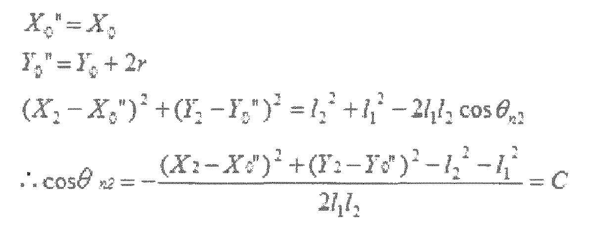
crank arm 38 of thecrank assembly 28 is vertically oriented at the top dead center. Furthermore, (X0", Y0") indicates the position of the LED M3 when thecrank arm 38 of thecrank assembly 28 is vertically oriented at the top dead center, while (X2, Y2) indicates the position of the LED M5. - Thus, the knee angle θn2 is expressed according to the following Equation (20). θ n2 = Cos -1 C (20)
- Furthermore, in regards to an angle γ, the relationships expressed by the following Equations are established.

crank arm 38 of thecrank assembly 28 is vertically oriented at the top dead center. - Thus, the angle γ is expressed according to the following Equation (21).

- In regards to a lower leg angle θ1" and the angle γ, the relationship expressed by the following Equation (22) is established.

crank arm 38 of thecrank assembly 28 is vertically oriented at the top dead center. - Based on Equations (21) and (22), the relationship expressed by the following Equation (23) is established.

- Furthermore, in regards to an upper leg angle θ2" and a back angle θback, the relationships expressed by the following Equations (24) and (25) are established.


crank arm 38 of thecrank assembly 28 is vertically oriented at the top dead center. Furthermore, the back angle θback is defined as an angle at the LED M5 enclosed by the horizontal line extending through the LED M5 and the line from the LED M5 to the LED M6. - Accordingly, the handlebar position (X3, Y3) can be calculated by the following Equations (26) and (27).


- In the illustrated embodiment, the
controller 12 calculates the suitable handlebar position (X3, Y3) based on the above-mentioned Equations (26) and (27). Specifically, thecontroller 12 calculates the lower leg angle θ1 based on Equation (23) using the seat position (X2, Y2), the first length 11, thesecond length 12, the crank arm length r. In the illustrated embodiment, thecontroller 12 calculates the lower leg angle θ1" based on Equation (23) using the measured values of the first length 11 and thesecond length 12 that have been measured as explained above, and the preset value of the crank arm length r. Furthermore, thecontroller 12 calculates the lower leg angle θ1" based on Equation (23) using the seat position (X2, Y2) calculated in step S14. Furthermore, thecontroller 12 calculates the upper leg angle θ2" based on Equation (24) using the calculated lower leg angle θ1", and the knee angle θn2 calculated based on Equation (20). Furthermore, thecontroller 12 calculates the back angle θback based on Equation (25) using the calculated upper leg angle θ2" and the hip angle θh. Specifically, thecontroller 12 calculates the back angle θback based on Equation (25) using the preset target value of the hip angle θh. The preset target value of the hip angle θh is determined based on the parameter range table 62 shown inFigures 5 to 7 according to the hip flexibility level, the bicycle type and the riding type (i.e., the flexibility level of therider body 18 and the category information). - Then, the
controller 12 further calculates the suitable handlebar position (X3, Y3) based on the above-mentioned Equations (26) and (27) using the position (X2, Y2) of theseat 26 calculated instep S 14, the third length 13, thefourth length 14, thefifth length 15, the armpit angle θ4, the elbow angle θ5, and the back angle θback. In the illustrated embodiment, thecontroller 12 calculates the handlebar position (X3, Y3) based on the above-mentioned Equations (26) and (27) using the measured values of the third to fifth lengths 13 to 15 that have been measured as explained above, the calculated value of the back angle θback that has been calculated as mentioned above, and preset values of the armpit angle θ4 and the elbow angle θ5. Specifically, thecontroller 12 sets the preset parameters for the armpit angle θ4, the elbow angle θ5 and the first deviation s using the preset parameter table 64 shown inFigure 8 based on the bicycle type of the category information inputted by the rider or the operator of the bicyclefitting system 10 to thecomputer system 46. In the illustrated embodiment, thecontroller 12 calculates Equations (26) and (27) using the preset values of the armpit angle θ4 and the elbow angle θ5. However, alternatively, thecontroller 12 can calculate Equation (26) and (27) using measured values of the armpit angle θ4 and the elbow angle θ5. Furthermore, in the illustrated embodiment, the position (X0, Y0) of the LED M3 is used as a reference position to calculate the suitable handlebar position (X3, Y3) of thehandlebar 24. Thus, the position (X0, Y0) of the LED M3 can be set as (0, 0). - Next, as shown in
Figure 13 , thecontroller 12 outputs adjustment directions of thehandlebar 24 and adjustment amounts of thehandlebar 24 on thedisplay screen 48 of the computer system 46 (step S23 inFigure 11 ). Specifically, thecontroller 12 is further programmed to determine the adjustment directions of the handlebar 24 (e.g., the bicycle component) and the adjustment amounts of the handlebar 24 (e.g., the bicycle component) based on the suitable handlebar position (X3, Y3) (e.g., the bicycle component position). Specifically, in the illustrated embodiment, thecontroller 12 calculates the deviation between the position (X3, Y3) of thehandlebar 24 calculated in step S21 and the suitable handlebar position (X3, Y3) of thehandlebar 24 calculated in step S22. Specifically, thecontroller 12 subtract the position (X3, Y3) of thehandlebar 24 calculated in step S21 from the suitable handlebar position (X3, Y3) of thehandlebar 24 calculated in step S 22 to obtain the adjustment directions of thehandlebar 24 and the adjustment amounts of thehandlebar 24 in the horizontal direction X and in the vertical direction Y. Then, as shown inFigure 13 , thecontroller 12 displays arrows R indicative of the adjustment directions of thehandlebar 24 together with the adjustment amounts of thehandlebar 24. In other words, thecontroller 12 is further programmed to output the adjustment directions and the adjustment amounts on the display screen 48 (e.g., the output apparatus). In the illustrated embodiment, the indicators M11 and M12, the adjustment directions and the adjustment amounts are displayed in the same display image as shown inFigure 13 . However, alternatively, the indicators M11 and M12, the adjustment directions and the adjustment amounts can be displayed in different display images, respectively. - The rider or the operator of the bicycle
fitting system 10 adjusts thehandlebar 24 with respect to theframe 22 according to the graphic image displayed on thedisplay screen 48. While adjusting thehandlebar 24 with respect to theframe 22, the bicyclefitting equipment 16 can output the adjustment data indicative of the actual handlebar adjustment amounts to thecontroller 12 in the horizontal direction X and in the vertical direction Y as (Δx2, Δy2). Thecontroller 12 further outputs the adjustment directions of thehandlebar 24 and the adjustment amounts of thehandlebar 24 according to the handlebar adjustment amounts (Δx2, Δy2) from the bicyclefitting equipment 16. Specifically, if the handlebar adjustment amounts (Δx2, Δy2) from the bicyclefitting equipment 16 match with the adjustment amounts calculated in step S23, then the arrows R on thedisplay screen 48 disappear to notify that the adjustment of thehandlebar 24 with respect to theframe 22 has been completed. - Next, the
controller 12 measures the set of the rider body parameters of therider body 18 while the rider rotates thecrank assembly 28 ten times in the same manner as step S11 (step S24 inFigure 11 ). - As shown in
Figure 11 , in step S25, thecontroller 12 determines whether the measured knee angle θn measured in step S24 falls within the parameter range for the knee angle θn in the same manner asstep S 12. Furthermore, thecontroller 12 also determines whether the measured hip angle θh measured in step S24 falls within the parameter range for the hip angle θh in the same manner as step S12. Then, thecontroller 12 outputs the bicycle fitting information (i.e., the indicators M11 and M12) on thedisplay screen 48 of thecomputer system 46 shown inFigure 13 in the same manner as step S12. - As shown in
Figure 11 , if thecontroller 12 determines that the measured hip angle θh measured in step S24 falls outside the parameter range for the hip angle θh in the same manner as step S12 ("No" in step S26), then the process returns to step S21. In other words, while the indicator M12 on thedisplay screen 48 is displayed in red, the processes from step S21 to S26 are repeated until the indicator M12 is displayed in green or yellow. In this case, the suitable handlebar position (X3, Y3) of thehandlebar 24 calculated in step S22 will be updated as a temporal bicycle component position while the measured hip angle θh measured in step S 16 or step S24 falls outside the parameter range for the hip angle θh. In other words, thecontroller 12 is further programmed to determine the temporal bicycle component position of the handlebar 24 (e.g., the bicycle component) based on the rider body parameters in response to measured hip angle θh (e.g., the one of the rider body parameters) falling outside the parameter range of the measured hip angle θh (e.g., the one of the rider body parameters). Then, the bicyclefitting equipment 16 is adjusted based on the temporal bicycle component position in step S25. On the other hand, if thecontroller 12 determines that the measured hip angle θh measured in step S24 falls within the parameter range for the hip angle θh in the same manner as step S12 ("Yes" in step S26), then the bicycle fitting process is completed. In other words, when the indicator M12 on thedisplay screen 48 is displayed in green or yellow, the adjustment of thehandlebar 24 is completed. - After determining the suitable seat position (X2, Y2) and the suitable handlebar position (X3, Y3), the
controller 12 output the bicycle fitting information on thedisplay screen 48. In the illustrated embodiment, thecontroller 12 output the bicycle fitting information as shown inFigure 14 in response to the rider or the operator of the bicyclefitting system 10 pressing a finish button provided by the bicycle fitting software. However, thecontroller 12 can automatically output the bicycle fitting information as shown inFigure 14 in response to thecontroller 12 determining that the measured hip angle θh measured in step S24 falls within the parameter range for the hip angle θh in step S26. In the illustrated embodiment, as shown inFigure 14 , thecontroller 12 graphically displays the measured flexibility levels (i.e., the knee flexibility level "knee angle", and the hip flexibility level "hip angle") as the bicycle fitting information. - Furthermore, as shown in
Figure 14 , thecontroller 12 also graphically displays the initial body parameters and the adjusted body parameters as the bicycle fitting information. In particular, thecontroller 12 outputs a graphic image showing the initial value of the knee angle On ("120 degree" inFigure 14 ) and the initial value of the hip angle θh ("30 degree" inFigure 14 ) that are measured in step S11 inFigure 10 . On the other hand, thecontroller 12 also outputs a graphic image showing the adjusted value of the knee angle θn ("140 degree" inFigure 14 ) and the adjusted value of the hip angle θh ("50 degree" inFigure 14 ) that are measured in step S24 inFigure 11 for the last time. - Moreover, as shown in
Figure 14 , thecontroller 12 graphically displays the initial seat position (X2, Y2), the initial handlebar position (X3, Y3), the suitable seat position (X2, Y2), and the suitable handlebar position (X3, Y3) on the orthogonal coordinate system with the axes extending in the horizontal direction X and in the vertical direction Y, respectively, as the bicycle fitting information to reflect the positions to the user's bicycle. The orthogonal coordinate system has the origin at the center axis of thecrank axle 42. One parameter Y indicates the vertical position, while the other parameter X indicates the horizontal portion. In other words, thecontroller 12 is further programmed to output the suitable seat position (X2, Y2) and the suitable handlebar position (X3, Y3) (e.g., the bicycle fitting information) based on the knee angle On and the hip angle On (e.g., the rider body parameters), and the parameter ranges of the knee angle θn and the hip angle θn (e.g., the rider body parameters). In the illustrated embodiment, the suitable seat position (X2, Y2) and the suitable handlebar position (X3, Y3) (e.g., the bicycle fitting information) indicates the bicycle component positions of the bicycle component. Furthermore, thecontroller 12 is further programmed to output the suitable seat position (X2, Y2) and the suitable handlebar position (X3, Y3) (e.g., the bicycle component positions) on the display screen (e.g., the output apparatus). In the illustrated embodiment, thecontroller 12 is further programmed to acquire the initial seat position (X2, Y2) of theseat 26 and the initial handlebar position (X3, Y3) of the handlebar (e.g., the initial bicycle component positions of the bicycle components). Thecontroller 12 is further programmed to output the suitable seat position (X2, Y2) and the suitable handlebar position (X3, Y3) (e.g., the bicycle component positions), and the initial seat position (X2, Y2) and the initial handlebar position (X3, Y3) (e.g., the initial bicycle component positions). In particular, thecontroller 12 outputs a graphic image showing the initial seat position (X2, Y2) that is calculated in step S 13 inFigure 10 for the first time, and the initial handlebar position (X3, Y3) that is calculated in step S21 inFigure 11 for the first time. On the other hand, thecontroller 12 also outputs a graphic image showing the suitable seat position (X2, Y2) that is calculated in step S 14 inFigure 10 for the last time, and the suitable handlebar position (X3, Y3) that is calculated in step S22 inFigure 11 for the last time. In the illustrated embodiment, the initial seat position (X2, Y2), the initial handlebar position (X3, Y3), the suitable seat position (X2, Y2), and the suitable handlebar position (X3, Y3) are output as positions relative to the center axis of thecrank axle 42. Thecontroller 12 saves the calculation results in a CSV file and the like. In the illustrated embodiment, thecontroller 12 outputs the bicycle fitting information shown inFigures 12 to 14 on thedisplay screen 48. However, alternatively or additionally, thecontroller 12 can print the bicycle fitting information shown inFigures 12 to 14 on a sheet through a printer device. - In understanding the scope of the present invention, the term "coupled" or "coupling", as used herein, encompasses configurations in which an element is directly secured to another element by affixing the element directly to the other element; configurations in which the element is indirectly secured to the other element by affixing the element to the intermediate member(s) which in turn are affixed to the other element; and configurations in which one element is integral with another element, i.e. one element is essentially part of the other element. This definition also applies to words of similar meaning, for example, "joined", "connected", "attached", "mounted", "bonded", "fixed" and their derivatives.
- In understanding the scope of the present invention, the term "comprising" and its derivatives, as used herein, are intended to be open ended terms that specify the presence of the stated features, elements, components, groups, integers, and/or steps, but do not exclude the presence of other unstated features, elements, components, groups, integers and/or steps. The foregoing also applies to words having similar meanings such as the terms, "including", "having" and their derivatives.
- Also it will be understood that although the terms "first" and "second" may be used herein to describe various components these components should not be limited by these terms. These terms are only used to distinguish one component from another. Thus, for example, a first component discussed above could be termed a second component and vice-a-versa without departing from the teachings of the present invention. Also, the terms "part," "section," "portion," "member" or "element" when used in the singular can have the dual meaning of a single part or a plurality of parts. Finally, terms of degree such as "substantially", "about" and "approximately" as used herein mean an amount of deviation of the modified term such that the end result is not significantly changed.
- While only a preferred embodiment has been chosen to illustrate the present invention, it will be apparent to those skilled in the art from this disclosure that various changes and modifications can be made herein without departing from the scope of the invention as defined in the appended claims. For example, the size, shape, location or orientation of the various components can be changed as needed and/or desired so long as they do not substantially affect their intended function. Components that are shown directly connected or contacting each other can have intermediate structures disposed between them unless specifically stated otherwise. The functions of one element can be performed by two, and vice versa unless specifically stated otherwise. It is not necessary for all advantages to be present in a particular embodiment at the same time. Every feature which is unique from the prior art, alone or in combination with other features, also should be considered a separate description of further inventions by the applicant, including the structural and/or functional concepts embodied by such feature(s). Thus, the foregoing descriptions of the embodiment according to the present invention are provided for illustration only, and not for the purpose of limiting the invention as defined by the appended claims and their equivalents.
Claims (13)
- A bicycle fitting system comprising:a controller programmed to determine whether a current rider position of a rider is appropriate based on a flexibility level of a rider body of the rider.
- The bicycle fitting system according to claim 1, comprising
a motion capturing apparatus electrically connected to the controller,
the controller being further programmed to determine the flexibility level using the motion capturing apparatus. - The bicycle fitting system according to claim 2, wherein
the controller is programmed to measure a plurality of rider body parameters of the rider body using the motion capturing apparatus while the rider is on a bicycle fitting equipment. - The bicycle fitting system according to claim 3, wherein
the controller is programmed toset a parameter range of one of the rider body parameters based on the flexibility level, andoutput a bicycle fitting information based on both the rider body parameters and the parameter range of the one of the rider body parameters. - The bicycle fitting system according to claim 4, wherein
the bicycle fitting information indicates whether the one of the rider body parameters falls within the parameter range of the one of the rider body parameters. - The bicycle fitting system according to any one of claims 4 to 5, wherein
the controller is programmed toacquire category information indicative of at least one of a bicycle type and a riding type, andset the parameter range of the one of the rider body parameters based on the flexibility level and the category information. - The bicycle fitting system according to any one of claims 4 to 6, wherein
the controller is programmed to determine a temporal bicycle component position of a bicycle component based on the rider body parameters in response to the one of the rider body parameters falling outside the parameter range of the one of the rider body parameters and,
the bicycle fitting equipment is adjusted based on the temporal bicycle component position. - The bicycle fitting system according to any one of claims 4 to 7, wherein
the controller is programmed to display an indicator with a first predetermined status in response to the one of the rider body parameters falling within the parameter range of the one of the rider body parameters on a display screen, and/or
the controller is programmed to display the indicator with a second predetermined status in response to the one of the rider body parameters falling outside the parameter range of the one of the rider body parameters on the display screen, the second predetermined status being different from the first predetermined status. - The bicycle fitting system according to any one of claims 4 to 8, wherein
the bicycle fitting information indicates a bicycle component position of a bicycle component. - The bicycle fitting system according to claim 9, wherein
the controller is programmed to determine a setting position of at least one of a bicycle seat and a bicycle handle as the bicycle component position. - The bicycle fitting system according to any one of claims 9 to 10, wherein
the controller is programmed to output the bicycle component position on an output apparatus. - The bicycle fitting system according to any one of claims 9 to 11, wherein
the controller is programmed to acquire an initial bicycle component position of the bicycle component, and/or
the controller is programmed to output the bicycle component position and the initial bicycle component position. - The bicycle fitting system according to any one of claims 9 to 12, wherein
the controller is programmed to determine an adjustment direction of the bicycle component and an adjustment amount of the bicycle component based on the bicycle component position, and/or
the controller is programmed to output the adjustment direction and the adjustment amount on an output apparatus.
Applications Claiming Priority (1)
| Application Number | Priority Date | Filing Date | Title |
|---|---|---|---|
| US13/968,435 US9381417B2 (en) | 2013-08-16 | 2013-08-16 | Bicycle fitting system |
Publications (2)
| Publication Number | Publication Date |
|---|---|
| EP2837329A1 true EP2837329A1 (en) | 2015-02-18 |
| EP2837329B1 EP2837329B1 (en) | 2019-11-20 |
Family
ID=50473135
Family Applications (1)
| Application Number | Title | Priority Date | Filing Date |
|---|---|---|---|
| EP14164205.8A Active EP2837329B1 (en) | 2013-08-16 | 2014-04-10 | Bicycle fitting system |
Country Status (3)
| Country | Link |
|---|---|
| US (1) | US9381417B2 (en) |
| EP (1) | EP2837329B1 (en) |
| CN (1) | CN104368972B (en) |
Cited By (3)
| Publication number | Priority date | Publication date | Assignee | Title |
|---|---|---|---|---|
| EP2897700A1 (en) * | 2012-09-18 | 2015-07-29 | Dorel Hungary Kft Luxembourg Branch | Dynamic fit unit |
| WO2016108197A1 (en) * | 2014-12-30 | 2016-07-07 | Ergoview S.R.L. | Method and system for biomechanical analysis of the posture of a cyclist and automatic customized manufacture of bicycle parts |
| EP4549298A1 (en) * | 2023-11-01 | 2025-05-07 | Giant Manufacturing Co., Ltd. | System, method, and non-volatile computer-readable storage medium applied for bike fitting |
Families Citing this family (14)
| Publication number | Priority date | Publication date | Assignee | Title |
|---|---|---|---|---|
| US9999818B2 (en) * | 2012-08-27 | 2018-06-19 | Wahoo Fitness Llc | Bicycle trainer |
| TWI535419B (en) * | 2013-10-24 | 2016-06-01 | 歐立達股份有限公司 | A measuring system and method for analyzing the trajectory of knee movement of riding a bicycle |
| TWI643092B (en) * | 2016-08-10 | 2018-12-01 | Giant Manufacturing Co., Ltd. | Dynamic motion detection system |
| JP6686985B2 (en) * | 2017-08-03 | 2020-04-22 | カシオ計算機株式会社 | Trajectory estimation device, trajectory estimation method, and trajectory estimation program |
| US10384111B2 (en) * | 2017-11-08 | 2019-08-20 | Shu-Chiung Liao Lai | Bicycle trainer |
| TWI657354B (en) * | 2017-12-26 | 2019-04-21 | 艾蒙特科技有限公司 | Action analysis method and system |
| DE102018004093A1 (en) * | 2018-05-23 | 2019-11-28 | Jens Hollenbacher | Device for checking and adjusting a bicycle |
| CN111686462A (en) * | 2019-03-12 | 2020-09-22 | 天津大学 | Bicycle seat self-adaptive adjusting system based on electronic control lifting cylinder |
| TWI708628B (en) * | 2019-12-26 | 2020-11-01 | 財團法人工業技術研究院 | Sensing and feedback system for detecting motions of riding a spinning bike and method thereof |
| IT202100009284A1 (en) * | 2021-04-13 | 2022-10-13 | Ivan Bizzoni | POSTURAL DETECTION SYSTEM ON THE BICYCLE AND METHOD |
| TWI803937B (en) * | 2021-08-12 | 2023-06-01 | 財團法人成大研究發展基金會 | Dynamometric device for bicycles |
| EP4141774B1 (en) | 2021-08-28 | 2025-07-02 | SQlab GmbH | Method and system for selecting a bicycle product |
| US12499571B2 (en) * | 2021-12-06 | 2025-12-16 | MyVeloFit Inc. | System and method for selecting a sporting equipment |
| TWI859589B (en) | 2022-09-30 | 2024-10-21 | 財團法人工業技術研究院 | Measurement card, measurement system and measurement method using the same |
Citations (1)
| Publication number | Priority date | Publication date | Assignee | Title |
|---|---|---|---|---|
| US20070142177A1 (en) * | 2005-09-26 | 2007-06-21 | Crucial Innovation, Inc. | Computerized method and system for fitting a bicycle to a cyclist |
Family Cites Families (23)
| Publication number | Priority date | Publication date | Assignee | Title |
|---|---|---|---|---|
| US5077619A (en) | 1989-10-25 | 1991-12-31 | Tacan Corporation | High linearity optical transmitter |
| US5198877A (en) | 1990-10-15 | 1993-03-30 | Pixsys, Inc. | Method and apparatus for three-dimensional non-contact shape sensing |
| US5323286A (en) | 1992-12-31 | 1994-06-21 | Xerox Corporation | Method of determining tape length and tape pack position of a tape cassette |
| DE69431875T2 (en) | 1993-04-22 | 2003-05-28 | Image Guided Technologies, Inc. | ARRANGEMENT FOR DETERMINING THE MUTUAL POSITION OF BODIES |
| US5629115A (en) | 1993-04-30 | 1997-05-13 | Kabushiki Kaisha Toshiba | Exposure mask and method and apparatus for manufacturing the same |
| US5617857A (en) | 1995-06-06 | 1997-04-08 | Image Guided Technologies, Inc. | Imaging system having interactive medical instruments and methods |
| US5907395A (en) | 1997-06-06 | 1999-05-25 | Image Guided Technologies, Inc. | Optical fiber probe for position measurement |
| CA2240776C (en) | 1997-07-18 | 2006-01-10 | Image Guided Technologies, Inc. | Improved optical tracking system |
| JPH1173225A (en) * | 1997-08-29 | 1999-03-16 | Oki Electric Ind Co Ltd | Positioning method |
| US6141104A (en) | 1997-09-09 | 2000-10-31 | Image Guided Technologies, Inc. | System for determination of a location in three dimensional space |
| US6608688B1 (en) | 1998-04-03 | 2003-08-19 | Image Guided Technologies, Inc. | Wireless optical instrument for position measurement and method of use therefor |
| EP1153292B1 (en) | 1998-12-23 | 2011-08-24 | Image Guided Technologies, Inc. | A hybrid 3-d probe tracked by multiple sensors |
| US6497134B1 (en) | 2000-03-15 | 2002-12-24 | Image Guided Technologies, Inc. | Calibration of an instrument |
| US7742804B2 (en) | 2003-03-27 | 2010-06-22 | Ivan Faul | Means of tracking movement of bodies during medical treatment |
| US8950256B2 (en) * | 2006-08-29 | 2015-02-10 | Dorel Hungary Kft Luxembourg Branch | Dynamic fit unit |
| US7256899B1 (en) | 2006-10-04 | 2007-08-14 | Ivan Faul | Wireless methods and systems for three-dimensional non-contact shape sensing |
| US8294082B2 (en) | 2007-11-14 | 2012-10-23 | Boulder Innovation Group, Inc. | Probe with a virtual marker |
| US20100076721A1 (en) | 2008-09-23 | 2010-03-25 | Crucial Innovation, Inc. | Dynamic Sizing Apparatus, System, and Method of Using the Same |
| US20100306160A1 (en) | 2009-05-29 | 2010-12-02 | Crucial Innovation, Inc. | Generating and determining bicycle configurations conforming to constraints |
| US8638450B2 (en) | 2010-08-04 | 2014-01-28 | Boulder Innovation Group Inc. | Methods and systems for realizing reduced complexity in three-dimensional digitizer systems |
| US8687172B2 (en) | 2011-04-13 | 2014-04-01 | Ivan Faul | Optical digitizer with improved distance measurement capability |
| TWI497333B (en) * | 2011-06-14 | 2015-08-21 | Giant Mfg Co Ltd | Bicycle fitting method for producing bicycle, bicycle fitting system and computer program product |
| CN202461954U (en) * | 2011-12-31 | 2012-10-03 | 大连智云自动化装备股份有限公司 | Device for conveying machine body on engine assembly line |
-
2013
- 2013-08-16 US US13/968,435 patent/US9381417B2/en active Active
-
2014
- 2014-01-21 CN CN201410025981.5A patent/CN104368972B/en active Active
- 2014-04-10 EP EP14164205.8A patent/EP2837329B1/en active Active
Patent Citations (1)
| Publication number | Priority date | Publication date | Assignee | Title |
|---|---|---|---|---|
| US20070142177A1 (en) * | 2005-09-26 | 2007-06-21 | Crucial Innovation, Inc. | Computerized method and system for fitting a bicycle to a cyclist |
Non-Patent Citations (3)
| Title |
|---|
| FERRER-ROCA VENTURA ET AL: "Influence of saddle height on lower limb kinematics in well-trained cyclists: static vs. dynamic evaluation in bike fitting.", November 2012, JOURNAL OF STRENGTH AND CONDITIONING RESEARCH / NATIONAL STRENGTH & CONDITIONING ASSOCIATION NOV 2012, VOL. 26, NR. 11, PAGE(S) 3025 - 3029, ISSN: 1533-4287, XP002726990 * |
| SPECIALIZED BICYCLES BG FIT: "An outline of the BG FIT program and how it can benefit cyclistsworldwide, from the pro peloton to the weekend enthusiast.", March 2009 (2009-03-01), XP002726988, Retrieved from the Internet <URL:http://www.specialized.com/OA_MEDIA/pdf/BG%20FIT%20Whitepaper.pdf> [retrieved on 20140710] * |
| VELOFIT REVOLUTION: ERIC BOWEN: "Road Bike Fitting Guidelines: The Essentials for Proper Fit", 14 March 2011 (2011-03-14), XP002726989, Retrieved from the Internet <URL:http://www.velofitter.com/storage/Road_Bike_Fitting_Guidelines.3.14.11.pdf> [retrieved on 20140710] * |
Cited By (4)
| Publication number | Priority date | Publication date | Assignee | Title |
|---|---|---|---|---|
| EP2897700A1 (en) * | 2012-09-18 | 2015-07-29 | Dorel Hungary Kft Luxembourg Branch | Dynamic fit unit |
| WO2016108197A1 (en) * | 2014-12-30 | 2016-07-07 | Ergoview S.R.L. | Method and system for biomechanical analysis of the posture of a cyclist and automatic customized manufacture of bicycle parts |
| US10722166B2 (en) | 2014-12-30 | 2020-07-28 | Ergoview S.R.L. | Method and system for biomechanical analysis of the posture of a cyclist and automatic customized manufacture of bicycle parts |
| EP4549298A1 (en) * | 2023-11-01 | 2025-05-07 | Giant Manufacturing Co., Ltd. | System, method, and non-volatile computer-readable storage medium applied for bike fitting |
Also Published As
| Publication number | Publication date |
|---|---|
| US20150051718A1 (en) | 2015-02-19 |
| US9381417B2 (en) | 2016-07-05 |
| CN104368972A (en) | 2015-02-25 |
| CN104368972B (en) | 2017-11-28 |
| EP2837329B1 (en) | 2019-11-20 |
Similar Documents
| Publication | Publication Date | Title |
|---|---|---|
| EP2837329B1 (en) | Bicycle fitting system | |
| TWI802859B (en) | Method and apparatus for bicycle fitting and non-transitory computer-readable storage medium | |
| TWI721254B (en) | Bicycle electric device and method for determining an angle of a bicycle crank arm | |
| US10000249B2 (en) | Bicycle pedal | |
| TWI628108B (en) | Bicycle pedal | |
| JP6518721B2 (en) | Dynamic motion detection system | |
| WO2007008930A3 (en) | Orientation and motion sensing in athletic training systems, physical rehabilitation and evaluation systems, and hand-held devices | |
| WO2012056558A1 (en) | Pedaling target setting device, pedaling target setting method, pedaling target setting program, and medium that records pedaling target setting program | |
| US9199692B2 (en) | Clipless bicycle pedal with measuring device | |
| US20150306458A1 (en) | Pedaling state detecting apparatus | |
| US11400995B2 (en) | Bicycle computer | |
| US10856793B2 (en) | Wheel frame of driving wheel of a wheel chair including an ergometer including improved stabilization for increasing torque measurement of a user | |
| US20170296896A1 (en) | Measuring device and measuring method for pedal plane angle of bicycle | |
| EP3506154B1 (en) | System and method for motion analysis | |
| US20200107754A1 (en) | Cycling-posture analyzing system and method | |
| CN106289597B (en) | A method of using wearable plantar pressure detection device | |
| EP3164022A1 (en) | Helmet providing position feedback | |
| US9639151B2 (en) | Method and apparatus for presenting an option | |
| US10908632B2 (en) | Device and method for use in cycling | |
| CN111110247B (en) | Method and device for monitoring motion data index | |
| CN115671673B (en) | Posture Assist Adjustment Method and Device for Strength Training Equipment | |
| CN114812542B (en) | Turn indication method and device | |
| US20170189785A1 (en) | Personal excercise measuring safety system | |
| CN119469129A (en) | A method and device for monitoring bicycle riding posture | |
| KR20250135109A (en) | Cycling power and status measurement apparatus of riding device and related cloud-based system |
Legal Events
| Date | Code | Title | Description |
|---|---|---|---|
| 17P | Request for examination filed |
Effective date: 20140410 |
|
| AK | Designated contracting states |
Kind code of ref document: A1 Designated state(s): AL AT BE BG CH CY CZ DE DK EE ES FI FR GB GR HR HU IE IS IT LI LT LU LV MC MK MT NL NO PL PT RO RS SE SI SK SM TR |
|
| AX | Request for extension of the european patent |
Extension state: BA ME |
|
| PUAI | Public reference made under article 153(3) epc to a published international application that has entered the european phase |
Free format text: ORIGINAL CODE: 0009012 |
|
| R17P | Request for examination filed (corrected) |
Effective date: 20150818 |
|
| RBV | Designated contracting states (corrected) |
Designated state(s): AL AT BE BG CH CY CZ DE DK EE ES FI FR GB GR HR HU IE IS IT LI LT LU LV MC MK MT NL NO PL PT RO RS SE SI SK SM TR |
|
| RIN1 | Information on inventor provided before grant (corrected) |
Inventor name: INOUE, AKIRA |
|
| STAA | Information on the status of an ep patent application or granted ep patent |
Free format text: STATUS: EXAMINATION IS IN PROGRESS |
|
| 17Q | First examination report despatched |
Effective date: 20181128 |
|
| GRAP | Despatch of communication of intention to grant a patent |
Free format text: ORIGINAL CODE: EPIDOSNIGR1 |
|
| STAA | Information on the status of an ep patent application or granted ep patent |
Free format text: STATUS: GRANT OF PATENT IS INTENDED |
|
| INTG | Intention to grant announced |
Effective date: 20190605 |
|
| GRAS | Grant fee paid |
Free format text: ORIGINAL CODE: EPIDOSNIGR3 |
|
| GRAA | (expected) grant |
Free format text: ORIGINAL CODE: 0009210 |
|
| STAA | Information on the status of an ep patent application or granted ep patent |
Free format text: STATUS: THE PATENT HAS BEEN GRANTED |
|
| AK | Designated contracting states |
Kind code of ref document: B1 Designated state(s): AL AT BE BG CH CY CZ DE DK EE ES FI FR GB GR HR HU IE IS IT LI LT LU LV MC MK MT NL NO PL PT RO RS SE SI SK SM TR |
|
| REG | Reference to a national code |
Ref country code: GB Ref legal event code: FG4D |
|
| REG | Reference to a national code |
Ref country code: CH Ref legal event code: EP |
|
| REG | Reference to a national code |
Ref country code: DE Ref legal event code: R096 Ref document number: 602014057001 Country of ref document: DE |
|
| REG | Reference to a national code |
Ref country code: IE Ref legal event code: FG4D |
|
| REG | Reference to a national code |
Ref country code: AT Ref legal event code: REF Ref document number: 1203227 Country of ref document: AT Kind code of ref document: T Effective date: 20191215 |
|
| REG | Reference to a national code |
Ref country code: NL Ref legal event code: FP |
|
| REG | Reference to a national code |
Ref country code: LT Ref legal event code: MG4D |
|
| PG25 | Lapsed in a contracting state [announced via postgrant information from national office to epo] |
Ref country code: ES Free format text: LAPSE BECAUSE OF FAILURE TO SUBMIT A TRANSLATION OF THE DESCRIPTION OR TO PAY THE FEE WITHIN THE PRESCRIBED TIME-LIMIT Effective date: 20191120 Ref country code: SE Free format text: LAPSE BECAUSE OF FAILURE TO SUBMIT A TRANSLATION OF THE DESCRIPTION OR TO PAY THE FEE WITHIN THE PRESCRIBED TIME-LIMIT Effective date: 20191120 Ref country code: LV Free format text: LAPSE BECAUSE OF FAILURE TO SUBMIT A TRANSLATION OF THE DESCRIPTION OR TO PAY THE FEE WITHIN THE PRESCRIBED TIME-LIMIT Effective date: 20191120 Ref country code: LT Free format text: LAPSE BECAUSE OF FAILURE TO SUBMIT A TRANSLATION OF THE DESCRIPTION OR TO PAY THE FEE WITHIN THE PRESCRIBED TIME-LIMIT Effective date: 20191120 Ref country code: GR Free format text: LAPSE BECAUSE OF FAILURE TO SUBMIT A TRANSLATION OF THE DESCRIPTION OR TO PAY THE FEE WITHIN THE PRESCRIBED TIME-LIMIT Effective date: 20200221 Ref country code: NO Free format text: LAPSE BECAUSE OF FAILURE TO SUBMIT A TRANSLATION OF THE DESCRIPTION OR TO PAY THE FEE WITHIN THE PRESCRIBED TIME-LIMIT Effective date: 20200220 Ref country code: FI Free format text: LAPSE BECAUSE OF FAILURE TO SUBMIT A TRANSLATION OF THE DESCRIPTION OR TO PAY THE FEE WITHIN THE PRESCRIBED TIME-LIMIT Effective date: 20191120 Ref country code: BG Free format text: LAPSE BECAUSE OF FAILURE TO SUBMIT A TRANSLATION OF THE DESCRIPTION OR TO PAY THE FEE WITHIN THE PRESCRIBED TIME-LIMIT Effective date: 20200220 |
|
| PG25 | Lapsed in a contracting state [announced via postgrant information from national office to epo] |
Ref country code: RS Free format text: LAPSE BECAUSE OF FAILURE TO SUBMIT A TRANSLATION OF THE DESCRIPTION OR TO PAY THE FEE WITHIN THE PRESCRIBED TIME-LIMIT Effective date: 20191120 Ref country code: HR Free format text: LAPSE BECAUSE OF FAILURE TO SUBMIT A TRANSLATION OF THE DESCRIPTION OR TO PAY THE FEE WITHIN THE PRESCRIBED TIME-LIMIT Effective date: 20191120 Ref country code: IS Free format text: LAPSE BECAUSE OF FAILURE TO SUBMIT A TRANSLATION OF THE DESCRIPTION OR TO PAY THE FEE WITHIN THE PRESCRIBED TIME-LIMIT Effective date: 20200320 |
|
| PG25 | Lapsed in a contracting state [announced via postgrant information from national office to epo] |
Ref country code: AL Free format text: LAPSE BECAUSE OF FAILURE TO SUBMIT A TRANSLATION OF THE DESCRIPTION OR TO PAY THE FEE WITHIN THE PRESCRIBED TIME-LIMIT Effective date: 20191120 |
|
| PG25 | Lapsed in a contracting state [announced via postgrant information from national office to epo] |
Ref country code: RO Free format text: LAPSE BECAUSE OF FAILURE TO SUBMIT A TRANSLATION OF THE DESCRIPTION OR TO PAY THE FEE WITHIN THE PRESCRIBED TIME-LIMIT Effective date: 20191120 Ref country code: EE Free format text: LAPSE BECAUSE OF FAILURE TO SUBMIT A TRANSLATION OF THE DESCRIPTION OR TO PAY THE FEE WITHIN THE PRESCRIBED TIME-LIMIT Effective date: 20191120 Ref country code: PT Free format text: LAPSE BECAUSE OF FAILURE TO SUBMIT A TRANSLATION OF THE DESCRIPTION OR TO PAY THE FEE WITHIN THE PRESCRIBED TIME-LIMIT Effective date: 20200412 Ref country code: DK Free format text: LAPSE BECAUSE OF FAILURE TO SUBMIT A TRANSLATION OF THE DESCRIPTION OR TO PAY THE FEE WITHIN THE PRESCRIBED TIME-LIMIT Effective date: 20191120 Ref country code: CZ Free format text: LAPSE BECAUSE OF FAILURE TO SUBMIT A TRANSLATION OF THE DESCRIPTION OR TO PAY THE FEE WITHIN THE PRESCRIBED TIME-LIMIT Effective date: 20191120 |
|
| PGFP | Annual fee paid to national office [announced via postgrant information from national office to epo] |
Ref country code: NL Payment date: 20200420 Year of fee payment: 7 |
|
| REG | Reference to a national code |
Ref country code: AT Ref legal event code: MK05 Ref document number: 1203227 Country of ref document: AT Kind code of ref document: T Effective date: 20191120 |
|
| REG | Reference to a national code |
Ref country code: DE Ref legal event code: R097 Ref document number: 602014057001 Country of ref document: DE |
|
| PG25 | Lapsed in a contracting state [announced via postgrant information from national office to epo] |
Ref country code: SM Free format text: LAPSE BECAUSE OF FAILURE TO SUBMIT A TRANSLATION OF THE DESCRIPTION OR TO PAY THE FEE WITHIN THE PRESCRIBED TIME-LIMIT Effective date: 20191120 Ref country code: SK Free format text: LAPSE BECAUSE OF FAILURE TO SUBMIT A TRANSLATION OF THE DESCRIPTION OR TO PAY THE FEE WITHIN THE PRESCRIBED TIME-LIMIT Effective date: 20191120 |
|
| PLBE | No opposition filed within time limit |
Free format text: ORIGINAL CODE: 0009261 |
|
| STAA | Information on the status of an ep patent application or granted ep patent |
Free format text: STATUS: NO OPPOSITION FILED WITHIN TIME LIMIT |
|
| REG | Reference to a national code |
Ref country code: DE Ref legal event code: R082 Ref document number: 602014057001 Country of ref document: DE Representative=s name: SONNENBERG HARRISON PARTNERSCHAFT MBB, DE Ref country code: DE Ref legal event code: R082 Ref document number: 602014057001 Country of ref document: DE Representative=s name: SONNENBERG HARRISON PARTNERSCHAFT MBB PATENT- , DE |
|
| 26N | No opposition filed |
Effective date: 20200821 |
|
| PG25 | Lapsed in a contracting state [announced via postgrant information from national office to epo] |
Ref country code: SI Free format text: LAPSE BECAUSE OF FAILURE TO SUBMIT A TRANSLATION OF THE DESCRIPTION OR TO PAY THE FEE WITHIN THE PRESCRIBED TIME-LIMIT Effective date: 20191120 Ref country code: MC Free format text: LAPSE BECAUSE OF FAILURE TO SUBMIT A TRANSLATION OF THE DESCRIPTION OR TO PAY THE FEE WITHIN THE PRESCRIBED TIME-LIMIT Effective date: 20191120 Ref country code: PL Free format text: LAPSE BECAUSE OF FAILURE TO SUBMIT A TRANSLATION OF THE DESCRIPTION OR TO PAY THE FEE WITHIN THE PRESCRIBED TIME-LIMIT Effective date: 20191120 Ref country code: AT Free format text: LAPSE BECAUSE OF FAILURE TO SUBMIT A TRANSLATION OF THE DESCRIPTION OR TO PAY THE FEE WITHIN THE PRESCRIBED TIME-LIMIT Effective date: 20191120 |
|
| REG | Reference to a national code |
Ref country code: CH Ref legal event code: PL |
|
| PG25 | Lapsed in a contracting state [announced via postgrant information from national office to epo] |
Ref country code: CH Free format text: LAPSE BECAUSE OF NON-PAYMENT OF DUE FEES Effective date: 20200430 Ref country code: IT Free format text: LAPSE BECAUSE OF FAILURE TO SUBMIT A TRANSLATION OF THE DESCRIPTION OR TO PAY THE FEE WITHIN THE PRESCRIBED TIME-LIMIT Effective date: 20191120 Ref country code: FR Free format text: LAPSE BECAUSE OF NON-PAYMENT OF DUE FEES Effective date: 20200430 Ref country code: LU Free format text: LAPSE BECAUSE OF NON-PAYMENT OF DUE FEES Effective date: 20200410 Ref country code: LI Free format text: LAPSE BECAUSE OF NON-PAYMENT OF DUE FEES Effective date: 20200430 |
|
| REG | Reference to a national code |
Ref country code: BE Ref legal event code: MM Effective date: 20200430 |
|
| PG25 | Lapsed in a contracting state [announced via postgrant information from national office to epo] |
Ref country code: BE Free format text: LAPSE BECAUSE OF NON-PAYMENT OF DUE FEES Effective date: 20200430 |
|
| GBPC | Gb: european patent ceased through non-payment of renewal fee |
Effective date: 20200410 |
|
| PG25 | Lapsed in a contracting state [announced via postgrant information from national office to epo] |
Ref country code: IE Free format text: LAPSE BECAUSE OF NON-PAYMENT OF DUE FEES Effective date: 20200410 Ref country code: GB Free format text: LAPSE BECAUSE OF NON-PAYMENT OF DUE FEES Effective date: 20200410 |
|
| REG | Reference to a national code |
Ref country code: NL Ref legal event code: MM Effective date: 20210501 |
|
| PG25 | Lapsed in a contracting state [announced via postgrant information from national office to epo] |
Ref country code: NL Free format text: LAPSE BECAUSE OF NON-PAYMENT OF DUE FEES Effective date: 20210501 |
|
| PG25 | Lapsed in a contracting state [announced via postgrant information from national office to epo] |
Ref country code: TR Free format text: LAPSE BECAUSE OF FAILURE TO SUBMIT A TRANSLATION OF THE DESCRIPTION OR TO PAY THE FEE WITHIN THE PRESCRIBED TIME-LIMIT Effective date: 20191120 Ref country code: MT Free format text: LAPSE BECAUSE OF FAILURE TO SUBMIT A TRANSLATION OF THE DESCRIPTION OR TO PAY THE FEE WITHIN THE PRESCRIBED TIME-LIMIT Effective date: 20191120 Ref country code: CY Free format text: LAPSE BECAUSE OF FAILURE TO SUBMIT A TRANSLATION OF THE DESCRIPTION OR TO PAY THE FEE WITHIN THE PRESCRIBED TIME-LIMIT Effective date: 20191120 |
|
| PG25 | Lapsed in a contracting state [announced via postgrant information from national office to epo] |
Ref country code: MK Free format text: LAPSE BECAUSE OF FAILURE TO SUBMIT A TRANSLATION OF THE DESCRIPTION OR TO PAY THE FEE WITHIN THE PRESCRIBED TIME-LIMIT Effective date: 20191120 |
|
| P01 | Opt-out of the competence of the unified patent court (upc) registered |
Effective date: 20230424 |
|
| PGFP | Annual fee paid to national office [announced via postgrant information from national office to epo] |
Ref country code: DE Payment date: 20260305 Year of fee payment: 13 |