EP2836147B1 - Delivery system for cartilage repair, preservation and growth by stimulation of bone-chondral interphase - Google Patents
Delivery system for cartilage repair, preservation and growth by stimulation of bone-chondral interphase Download PDFInfo
- Publication number
- EP2836147B1 EP2836147B1 EP13775734.0A EP13775734A EP2836147B1 EP 2836147 B1 EP2836147 B1 EP 2836147B1 EP 13775734 A EP13775734 A EP 13775734A EP 2836147 B1 EP2836147 B1 EP 2836147B1
- Authority
- EP
- European Patent Office
- Prior art keywords
- bone
- exemplary
- impact cap
- hub
- distal portion
- Prior art date
- Legal status (The legal status is an assumption and is not a legal conclusion. Google has not performed a legal analysis and makes no representation as to the accuracy of the status listed.)
- Active
Links
- 210000000845 cartilage Anatomy 0.000 title description 31
- 230000008439 repair process Effects 0.000 title description 16
- 230000016507 interphase Effects 0.000 title description 10
- 238000004321 preservation Methods 0.000 title description 3
- 230000000638 stimulation Effects 0.000 title description 3
- 210000000988 bone and bone Anatomy 0.000 claims description 66
- 239000003814 drug Substances 0.000 claims description 35
- 238000005520 cutting process Methods 0.000 claims description 30
- 210000001519 tissue Anatomy 0.000 claims description 11
- 238000010079 rubber tapping Methods 0.000 claims description 10
- 230000001054 cortical effect Effects 0.000 claims description 8
- 239000007788 liquid Substances 0.000 claims description 4
- 210000004369 blood Anatomy 0.000 claims description 3
- 239000008280 blood Substances 0.000 claims description 3
- NRTOMJZYCJJWKI-UHFFFAOYSA-N Titanium nitride Chemical compound [Ti]#N NRTOMJZYCJJWKI-UHFFFAOYSA-N 0.000 claims description 2
- 239000000126 substance Substances 0.000 claims 3
- 210000003127 knee Anatomy 0.000 description 39
- 238000000034 method Methods 0.000 description 38
- 210000004623 platelet-rich plasma Anatomy 0.000 description 38
- 238000002347 injection Methods 0.000 description 23
- 239000007924 injection Substances 0.000 description 23
- 238000011282 treatment Methods 0.000 description 17
- 210000000629 knee joint Anatomy 0.000 description 14
- 102100039619 Granulocyte colony-stimulating factor Human genes 0.000 description 13
- 101000746367 Homo sapiens Granulocyte colony-stimulating factor Proteins 0.000 description 13
- 230000001225 therapeutic effect Effects 0.000 description 13
- 210000001185 bone marrow Anatomy 0.000 description 12
- 210000004027 cell Anatomy 0.000 description 10
- 210000001503 joint Anatomy 0.000 description 10
- 210000000130 stem cell Anatomy 0.000 description 10
- UXVMQQNJUSDDNG-UHFFFAOYSA-L Calcium chloride Chemical compound [Cl-].[Cl-].[Ca+2] UXVMQQNJUSDDNG-UHFFFAOYSA-L 0.000 description 9
- 229940079593 drug Drugs 0.000 description 9
- 238000005553 drilling Methods 0.000 description 8
- 208000014674 injury Diseases 0.000 description 8
- 229910001220 stainless steel Inorganic materials 0.000 description 7
- 239000010935 stainless steel Substances 0.000 description 7
- 238000002560 therapeutic procedure Methods 0.000 description 7
- 210000003484 anatomy Anatomy 0.000 description 6
- 238000013459 approach Methods 0.000 description 6
- 229910001628 calcium chloride Inorganic materials 0.000 description 6
- 239000001110 calcium chloride Substances 0.000 description 6
- 210000001624 hip Anatomy 0.000 description 6
- 210000004394 hip joint Anatomy 0.000 description 6
- 239000000463 material Substances 0.000 description 6
- 229910052751 metal Inorganic materials 0.000 description 6
- 239000002184 metal Substances 0.000 description 6
- 229940124597 therapeutic agent Drugs 0.000 description 6
- 230000008733 trauma Effects 0.000 description 6
- 208000013201 Stress fracture Diseases 0.000 description 5
- 108090000190 Thrombin Proteins 0.000 description 5
- 230000007547 defect Effects 0.000 description 5
- 238000002594 fluoroscopy Methods 0.000 description 5
- 208000015181 infectious disease Diseases 0.000 description 5
- 230000002980 postoperative effect Effects 0.000 description 5
- 229960004072 thrombin Drugs 0.000 description 5
- 210000000689 upper leg Anatomy 0.000 description 5
- 239000003570 air Substances 0.000 description 4
- 230000008901 benefit Effects 0.000 description 4
- 230000006378 damage Effects 0.000 description 4
- 230000003412 degenerative effect Effects 0.000 description 4
- 208000028867 ischemia Diseases 0.000 description 4
- 230000002093 peripheral effect Effects 0.000 description 4
- 239000007787 solid Substances 0.000 description 4
- KIUKXJAPPMFGSW-DNGZLQJQSA-N (2S,3S,4S,5R,6R)-6-[(2S,3R,4R,5S,6R)-3-Acetamido-2-[(2S,3S,4R,5R,6R)-6-[(2R,3R,4R,5S,6R)-3-acetamido-2,5-dihydroxy-6-(hydroxymethyl)oxan-4-yl]oxy-2-carboxy-4,5-dihydroxyoxan-3-yl]oxy-5-hydroxy-6-(hydroxymethyl)oxan-4-yl]oxy-3,4,5-trihydroxyoxane-2-carboxylic acid Chemical compound CC(=O)N[C@H]1[C@H](O)O[C@H](CO)[C@@H](O)[C@@H]1O[C@H]1[C@H](O)[C@@H](O)[C@H](O[C@H]2[C@@H]([C@@H](O[C@H]3[C@@H]([C@@H](O)[C@H](O)[C@H](O3)C(O)=O)O)[C@H](O)[C@@H](CO)O2)NC(C)=O)[C@@H](C(O)=O)O1 KIUKXJAPPMFGSW-DNGZLQJQSA-N 0.000 description 3
- 102000055008 Matrilin Proteins Human genes 0.000 description 3
- 108010072582 Matrilin Proteins Proteins 0.000 description 3
- 239000012080 ambient air Substances 0.000 description 3
- 210000004271 bone marrow stromal cell Anatomy 0.000 description 3
- 239000011248 coating agent Substances 0.000 description 3
- 238000000576 coating method Methods 0.000 description 3
- 230000007423 decrease Effects 0.000 description 3
- 238000013461 design Methods 0.000 description 3
- 238000005516 engineering process Methods 0.000 description 3
- 239000012530 fluid Substances 0.000 description 3
- 229920002674 hyaluronan Polymers 0.000 description 3
- 229960003160 hyaluronic acid Drugs 0.000 description 3
- 210000002901 mesenchymal stem cell Anatomy 0.000 description 3
- 229940021182 non-steroidal anti-inflammatory drug Drugs 0.000 description 3
- 201000008482 osteoarthritis Diseases 0.000 description 3
- 238000002203 pretreatment Methods 0.000 description 3
- 210000005065 subchondral bone plate Anatomy 0.000 description 3
- 210000002303 tibia Anatomy 0.000 description 3
- 206010053567 Coagulopathies Diseases 0.000 description 2
- 108010071942 Colony-Stimulating Factors Proteins 0.000 description 2
- 102000007644 Colony-Stimulating Factors Human genes 0.000 description 2
- 208000002193 Pain Diseases 0.000 description 2
- ATJFFYVFTNAWJD-UHFFFAOYSA-N Tin Chemical compound [Sn] ATJFFYVFTNAWJD-UHFFFAOYSA-N 0.000 description 2
- 208000027418 Wounds and injury Diseases 0.000 description 2
- 210000000588 acetabulum Anatomy 0.000 description 2
- 210000000577 adipose tissue Anatomy 0.000 description 2
- 230000004075 alteration Effects 0.000 description 2
- 206010003246 arthritis Diseases 0.000 description 2
- 210000001188 articular cartilage Anatomy 0.000 description 2
- 239000002775 capsule Substances 0.000 description 2
- 210000001612 chondrocyte Anatomy 0.000 description 2
- 230000035602 clotting Effects 0.000 description 2
- 229940047120 colony stimulating factors Drugs 0.000 description 2
- 238000004891 communication Methods 0.000 description 2
- 210000001671 embryonic stem cell Anatomy 0.000 description 2
- 210000000968 fibrocartilage Anatomy 0.000 description 2
- 210000003714 granulocyte Anatomy 0.000 description 2
- 210000003035 hyaline cartilage Anatomy 0.000 description 2
- 238000003384 imaging method Methods 0.000 description 2
- 239000007943 implant Substances 0.000 description 2
- 238000003780 insertion Methods 0.000 description 2
- 230000037431 insertion Effects 0.000 description 2
- 238000013150 knee replacement Methods 0.000 description 2
- 230000000670 limiting effect Effects 0.000 description 2
- 238000002483 medication Methods 0.000 description 2
- 210000003205 muscle Anatomy 0.000 description 2
- 230000036961 partial effect Effects 0.000 description 2
- 230000037361 pathway Effects 0.000 description 2
- 238000002360 preparation method Methods 0.000 description 2
- 210000003314 quadriceps muscle Anatomy 0.000 description 2
- 230000009467 reduction Effects 0.000 description 2
- 230000002829 reductive effect Effects 0.000 description 2
- 230000008929 regeneration Effects 0.000 description 2
- 238000011069 regeneration method Methods 0.000 description 2
- 230000002441 reversible effect Effects 0.000 description 2
- 210000004872 soft tissue Anatomy 0.000 description 2
- 238000002604 ultrasonography Methods 0.000 description 2
- 210000000707 wrist Anatomy 0.000 description 2
- 208000006820 Arthralgia Diseases 0.000 description 1
- 208000030016 Avascular necrosis Diseases 0.000 description 1
- 241000196324 Embryophyta Species 0.000 description 1
- 108010029961 Filgrastim Proteins 0.000 description 1
- 206010020772 Hypertension Diseases 0.000 description 1
- 206010061218 Inflammation Diseases 0.000 description 1
- 206010061246 Intervertebral disc degeneration Diseases 0.000 description 1
- 208000003947 Knee Osteoarthritis Diseases 0.000 description 1
- 241001465754 Metazoa Species 0.000 description 1
- 206010030113 Oedema Diseases 0.000 description 1
- 206010031264 Osteonecrosis Diseases 0.000 description 1
- 208000031481 Pathologic Constriction Diseases 0.000 description 1
- 208000008469 Peptic Ulcer Diseases 0.000 description 1
- 208000001647 Renal Insufficiency Diseases 0.000 description 1
- 241000219061 Rheum Species 0.000 description 1
- 229910000831 Steel Inorganic materials 0.000 description 1
- 208000007536 Thrombosis Diseases 0.000 description 1
- RTAQQCXQSZGOHL-UHFFFAOYSA-N Titanium Chemical compound [Ti] RTAQQCXQSZGOHL-UHFFFAOYSA-N 0.000 description 1
- 230000002411 adverse Effects 0.000 description 1
- 229910052782 aluminium Inorganic materials 0.000 description 1
- XAGFODPZIPBFFR-UHFFFAOYSA-N aluminium Chemical compound [Al] XAGFODPZIPBFFR-UHFFFAOYSA-N 0.000 description 1
- 229960000074 biopharmaceutical Drugs 0.000 description 1
- 230000017531 blood circulation Effects 0.000 description 1
- 230000036770 blood supply Effects 0.000 description 1
- 208000015100 cartilage disease Diseases 0.000 description 1
- 229910010293 ceramic material Inorganic materials 0.000 description 1
- 239000003795 chemical substances by application Substances 0.000 description 1
- 238000011443 conventional therapy Methods 0.000 description 1
- 208000029078 coronary artery disease Diseases 0.000 description 1
- 229940111134 coxibs Drugs 0.000 description 1
- 239000003255 cyclooxygenase 2 inhibitor Substances 0.000 description 1
- 230000003247 decreasing effect Effects 0.000 description 1
- 230000007850 degeneration Effects 0.000 description 1
- 208000018180 degenerative disc disease Diseases 0.000 description 1
- 238000009792 diffusion process Methods 0.000 description 1
- 201000010099 disease Diseases 0.000 description 1
- 208000037265 diseases, disorders, signs and symptoms Diseases 0.000 description 1
- 239000013536 elastomeric material Substances 0.000 description 1
- 210000004700 fetal blood Anatomy 0.000 description 1
- 230000010006 flight Effects 0.000 description 1
- 230000006870 function Effects 0.000 description 1
- 210000004907 gland Anatomy 0.000 description 1
- 210000000527 greater trochanter Anatomy 0.000 description 1
- 239000003102 growth factor Substances 0.000 description 1
- 230000035876 healing Effects 0.000 description 1
- 230000036541 health Effects 0.000 description 1
- 210000003090 iliac artery Anatomy 0.000 description 1
- 230000004054 inflammatory process Effects 0.000 description 1
- 208000021600 intervertebral disc degenerative disease Diseases 0.000 description 1
- 201000006370 kidney failure Diseases 0.000 description 1
- 238000003754 machining Methods 0.000 description 1
- 238000004519 manufacturing process Methods 0.000 description 1
- 230000007246 mechanism Effects 0.000 description 1
- 150000002739 metals Chemical class 0.000 description 1
- 239000000203 mixture Substances 0.000 description 1
- 229940029345 neupogen Drugs 0.000 description 1
- 239000000041 non-steroidal anti-inflammatory agent Substances 0.000 description 1
- 231100000252 nontoxic Toxicity 0.000 description 1
- 230000003000 nontoxic effect Effects 0.000 description 1
- 230000003349 osteoarthritic effect Effects 0.000 description 1
- 230000000149 penetrating effect Effects 0.000 description 1
- 230000035515 penetration Effects 0.000 description 1
- 208000011906 peptic ulcer disease Diseases 0.000 description 1
- 210000005259 peripheral blood Anatomy 0.000 description 1
- 239000011886 peripheral blood Substances 0.000 description 1
- 229920001296 polysiloxane Polymers 0.000 description 1
- 230000008569 process Effects 0.000 description 1
- 230000002035 prolonged effect Effects 0.000 description 1
- 238000011160 research Methods 0.000 description 1
- 238000007789 sealing Methods 0.000 description 1
- 239000010959 steel Substances 0.000 description 1
- 230000036262 stenosis Effects 0.000 description 1
- 208000037804 stenosis Diseases 0.000 description 1
- 230000004936 stimulating effect Effects 0.000 description 1
- 239000000758 substrate Substances 0.000 description 1
- 238000001356 surgical procedure Methods 0.000 description 1
- 230000009885 systemic effect Effects 0.000 description 1
- 238000012360 testing method Methods 0.000 description 1
- 239000010936 titanium Substances 0.000 description 1
- 229910052719 titanium Inorganic materials 0.000 description 1
- 238000003466 welding Methods 0.000 description 1
Images


Classifications
-
- A—HUMAN NECESSITIES
- A61—MEDICAL OR VETERINARY SCIENCE; HYGIENE
- A61B—DIAGNOSIS; SURGERY; IDENTIFICATION
- A61B17/00—Surgical instruments, devices or methods
- A61B17/34—Trocars; Puncturing needles
- A61B17/3472—Trocars; Puncturing needles for bones, e.g. intraosseus injections
-
- A—HUMAN NECESSITIES
- A61—MEDICAL OR VETERINARY SCIENCE; HYGIENE
- A61M—DEVICES FOR INTRODUCING MEDIA INTO, OR ONTO, THE BODY; DEVICES FOR TRANSDUCING BODY MEDIA OR FOR TAKING MEDIA FROM THE BODY; DEVICES FOR PRODUCING OR ENDING SLEEP OR STUPOR
- A61M37/00—Other apparatus for introducing media into the body; Percutany, i.e. introducing medicines into the body by diffusion through the skin
-
- A—HUMAN NECESSITIES
- A61—MEDICAL OR VETERINARY SCIENCE; HYGIENE
- A61M—DEVICES FOR INTRODUCING MEDIA INTO, OR ONTO, THE BODY; DEVICES FOR TRANSDUCING BODY MEDIA OR FOR TAKING MEDIA FROM THE BODY; DEVICES FOR PRODUCING OR ENDING SLEEP OR STUPOR
- A61M5/00—Devices for bringing media into the body in a subcutaneous, intra-vascular or intramuscular way; Accessories therefor, e.g. filling or cleaning devices, arm-rests
- A61M5/14—Infusion devices, e.g. infusing by gravity; Blood infusion; Accessories therefor
- A61M5/158—Needles for infusions; Accessories therefor, e.g. for inserting infusion needles, or for holding them on the body
Definitions
- the present invention relates to delivery devices for various novel treatments for degenerative joints and discs, and for improved therapies for the delivery of therapeutic agents to hard to reach anatomical areas with minimal trauma so as to better implement such novel treatments.
- knee degeneration or osteoarthritis As an example, pain in knee OA, defined as loss of articular cartilage in the knee, is thought to be caused by increased pressure on the subchondral bone. Thus, there are changes in subchondral bone marrow that can be seen at the earliest stages of the onset of OA ( Lorieg et al, Rheum 7: 43-49, 2011 ).
- Non-steroidal anti-inflammatory drugs including the newer Cox-2 inhibitors. Although these medications decrease inflammation and pain, their prolonged use (i) is thought to have an adverse impact on cartilage and (ii) comes with complications of increased risk of hypertension, coronary artery disease, renal failure (especially in diabetics) and peptic ulcer disease.
- Hyaluronic acid has been shown to have some positive impact on cartilage. However, it has limited success rates in treating knee OA. Thus, while some studies show good success rates, others show rather poor ones. Furthermore, success rates decrease substantially in those patients with moderate to severe knee OA.
- Microfracture has been used for a very small subset of knee OA patients with small cartilage defects. This technique has seen limited success rates. The technique functions by creating fibrocartilage. However, if done excessively, microfracture can sometimes even accelerate the rate of cartilage loss.
- a drill is used to create a pathway.
- a device with a central cannula is used, which is initially provided with a miniature drill shaft and drill bit within it. The practitioner drills into the bone, and then removes the drill shaft and bit from the central cannula. Then a stylet is inserted, thus isolating the bone tissue from the outside environment. Finally, the stylet is removed and one of various appropriate therapies (e.g., drug, biologic or therapeutic) can be delivered via a syringe or other delivery device.
- therapies e.g., drug, biologic or therapeutic
- US 2005/107800 A1 discloses a bone tap that may be used to deliver fluid into bone to stabilize and/or strengthen the bone.
- the bone tap may include a passage. A distal portion of the bone tap may be threaded. Openings in a distal portion of the bone tap may communicate with the passage.
- the bone tap may be driven into bone, and material may be introduced to the passage. Material introduced to the passage may enter the bone through the openings. Thread flights of the bone tap proximal to the openings may inhibit retrograde backflow of material during introduction of the material into the bone. Material deposited in the bone may strengthen a bone and/or augment fixation of a bone fastener in the bone.
- a cannulated delivery device provided with a cutting tip and threads on its distal exterior can be provided which has considerable advantages over conventional devices. These include, for example, (i) ease of manufacture, (ii) use of the exemplary device being faster than conventional approaches, with both less table time and less steps, (iii) lesser exposure of internal tissues to ambient air, and thus less risk of infection, and (iv) lesser technical complexity leading to lesser complications.
- a delivery device directed to percutaneous intradiscal annular repair, or "PIARES" device can be used to introduce therapeutics intradiscally.
- the device is a two-needle device, with a first cannula/needle, with a finger grip at its proximal end, and a longer inner needle, which can then penetrate through the outer needle into the disc, and can then, for example, be used to introduce therapeutics, for example, via a syringe.
- the PIARES device becomes a completely closed system, and its use minimizes trauma.
- a surgical hand tool can be provided, used for the non-invasive placement and delivery of therapeutics, to a targeted site. This can be done through minimally invasive skin incision, or without any incision, as maybe desired.
- the delivery and placement of the therapeutic can be controlled and does not need a powered drill or guide wire.
- An exemplary device can have a closed pointed end, a threaded portion, and be provided with thread cutting/forming features, such as flute(s), and can have a shaft perforations to the central lumen at a distal end to deliver therapeutics or other preparations.
- means can be provided to attach a syringe in communication with the shaft's central lumen, and there may be a keyed engagement feature for attachment of a hand grip.
- the delivery device can be made of sufficient length to reach bone on either side of a desired or targeted joint, and to easily penetrate soft tissue and cortical bone to reach a targeted site in cancellous bone adjacent to a cartilage defect.
- the device's main shaft or drill portion can be made of hardened stainless steel, or the like, such as, for example, 400 series or 17-40 stainless steel, for example.
- the device can have, for example, an attachable/removable hand grip for ease of placement of the drill bit to a site, with a solid proximal end with which to tap or hammer, and with a grip for torquing the device through cortical bone and to guide a threaded shaft to a targeted site in cancellous bone, for example.
- the grip can have an ergonomic form for ease of use, such as a tri-lobe handle, which mimics the natural turn of a wrist in 120 degree increments.
- the device can have an impact cap to (i) provide impact anvil surface to protect a proximal luer during impaction, as well as to (ii) close the luer opening to a shaft lumen.
- exemplary methods address the BCI where early alterations can accelerate knee OA.
- Methods are provided to stimulate the subchondral bone marrow and expose the mesenchymal stem cells (MSCS) that come out of the bone marrow as a result, to growth factors from platelet-rich plasma (PRP) and very small embryonic like cells (VSELs).
- MSC mesenchymal stem cells
- PRP platelet-rich plasma
- VSELs very small embryonic like cells
- VSELs are known to be released after an injury resulting in enhanced repair in the animal stroke model ( Kucia et al: Cell Tissue Research 331: 125-134, (2008 ). This enhances cartilage repair and possible regeneration.
- MSCSs exposed to PRP differentiate into chondrocytes ( Mishra, et al: Tissue Eng. Methods 15: 431-435 (2009 )).
- Methods disclosed herein have a very low risk of infection, are significantly less expensive than major surgical procedures, and avoid the liability of metal implants or NSAID medications. Furthermore there is very little down time for patients undergoing this procedure inasmuch as it is performed on an outpatient basis with a quick return to work.
- cartilage issues can thus be treated from the "ground up.” Such an approach is analogous to how in agriculture plants are often treated by accessing their roots.
- technologies can be used that target the bone-cartilage interphase (BCI) to treat cartilage issues, as opposed to conventional "top down” approaches such as, for example, the current undesirable practice of microfracture.
- BCI bone-cartilage interphase
- microfracture creates fibrocartilage with very limited success in patients with cartilage defects.
- microfracture can only be used for a very small subset of knee osteoarthritis (“OA") patients - only those having small cartilage defects. If it is done excessively it itself can even lead to accelerated cartilage loss.
- OA knee osteoarthritis
- DJD medial joint knee degenerative disc disease
- GCSFs have not heretofore been used for cartilage repair.
- An exemplary GCSF that may be used can be, for example, Neupogen.
- the PRP can be delivered via one syringe, and either CaCI, thrombin or bone wax, for example, can be delivered via another syringe.
- a skilled, dexterous and quick practitioner may, for example, load both the PRP and CaCI into one syringe, if she can deliver the dose quickly enough so that no clotting occurs.
- the procedure can, and preferably should, be performed under fluoroscopy or ultrasound guidance to insure proper positioning of the delivery devices at the BCI and to further insure that there is no penetration through the cartilage, which would cause damage.
- the delivery device should be left in place for approximately 2 minutes to make sure a clot is formed.
- bone wax or the equivalent can be used, for example, to seal the entry instead of calcium chloride.
- an exemplary kit can contain, for example, two disposable delivery devices, to be used to inject at the BCI in the superior and inferior locations to a joint, as shown, for example, in Figs. 23-48 . Making them disposable minimizes the risk of infection.
- Such an exemplary kit can also be provided with a vial of bone wax and a 2cc vial of 10% calcium chloride solution, for example.
- the CaCI activates platelets and also forms a clot.
- the CaCI can be provided in a 1/10 th ratio to the biologic, thus for 1cc of stem cells and PRP, a 0.1 cc volume of CaCI may be used.
- the delivery device maybe reusable, and sterilizable, such as a version of the exemplary PecaBoo device described below.
- a device can have a disposable hub and drill portion (including impact cap - see Fig. 17 ), and a reusable handle, for example.
- bone marrow may be stimulated by the GCSFs to produce mesenchymal cells (MSC).
- MSC mesenchymal cells
- PRP PRP and VSELs
- MSCs and VSELs Very Small Embryonic Like stem cells
- both PRP and VSELs ma, for example, be delivered to the femoral and tibial compartments, for example, in an exemplary knee procedure. Sometimes just drilling is sufficient to stimulate cartilage growth, or to resolve an ischemia.
- a drill delivery device according to the present invention may be used:
- the bone marrow can be, for example, chemically stimulated with GCSF, while the bone marrow can also be stimulated mechanically by creating microtrauma above the bone marrow ("above" in the sense of a direction towards the knee joint). Such a microtrauma stimulates the bone marrow to produce more MSCS and VSEL cells, and also increases the blood supply to the bone-cartilage interface to allow for better repair.
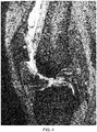
- FIGs. 1 and 2 are respectively axial and sagittal images of a patient's knee from a preoperative scan.
- Fig. 1 depicts an area of decreased blood flow due to an ischemia, as shown by the red arrow, also seen in Fig. 2 pointed to by the red and green arrows.
- Injections similarly performed according to the above described protocol, to the femoral and tibial compartments by drilling and injecting at the bone-cartilage interface, followed by injections into the knee joint.
- Figs. 3 and 4 are corresponding axial and sagittal images form a MRI taken three months following the treatment. As can be seen, significant new cartilage has grown, and the ischemia has been essentially resolved, as shown in Fig. 3 .
- Fig. 5 depicts side by side comparisons of sagittal images of a knee of a third patient.
- the left panel is an image form a preoperative scan
- the right panel a corresponding image from a post operative MRI.
- the post operative MRI showed an increase in cartilage matrix from 1.60 mm to 1.87 mm at the follow-up MRI.
- the therapeutic protocol described above can similarly be used for osteoarthritis and avascular necrosis, as well as for treating meniscal and labral injuries in the joints.
- the step of injecting GCSF for stimulating bone marrow may be skipped.
- the drilling/twisting alone of the delivery device (as described below) will stimulate bone marrow combined with PRP injection or injection of other biologics such as, for example, stem cells as an alternative.
- Joint Arthritis there is an alternative method for treating joint arthritis by using adipose tissue derived stem cells that can be injected intravenously combined with intra-articularly without drilling into the bone-cartilage interface. If that does not work then an alternative method is adipose derived stem cells injected intravenously, intra-articularly and into the bone-cartilage interface. This combination of systemic and local therapy is believed to be the next big step in biologic interventions for joint issues.
- the novel BCI device described below can be used for injecting the vertebral body.
- standard existing spinal needles can be used, or for example, a variation of the novel PIARES delivery device as shown in Figs. 10 and 11 .
- adipose tissue derived stem cells which first can be given intravenously along with caudal epidural injection. If this does not give results, then the adipose stem cells can, for example, be given intravenously along with intradiscal injection and caudal epidural, using, for example, a standard spinal needle, or, for example, a variation of the novel PIARES delivery device as shown in Figs. 10 and 11 .
- the therapeutic methods described above can be delivered in a safe and efficient manner using various delivery devices according to various exemplary embodiments, as next described.
- Figs. 6-9 depict an exemplary delivery device 100 according to exemplary embodiments.
- Fig. 6 depicts an exemplary distal end of an exemplary delivery device 100 according to exemplary embodiments.
- the device is essentially a hollow cannula with threads 130 on the outside of it.
- the threads 130 allow for controlled insertion and removal of the device.
- It has a cutting point 135 at its distal end, and immediately proximal to the cutting tip (i.e., above it) a series of holes 140 are provided to dispense various therapeutics.
- the solid slug at the tip of the device can be laser welded in place, for example, and the various holes in the cannula laser cut, for example.
- Exemplary dimensions are shown in Fig. 6 , but are understood to be merely exemplary, and not limiting.
- a user Given the solid cutting tip, a user first presets the device with hammer taps, and then can screw in the device a desired length. This can be done manually, or via a drill interface provided at the distal end of the device, for example. As described below, one can, for example, tap with a hammer to set the device into place into dense cortical bone, and then subsequently twist (or drill) to advance the delivery device into spongy bone (interior cancellous bone).
- Fig. 7 is an exploded view of an exemplary embodiment of the delivery device 100 (top panel), and a magnified view of an exemplary proximal portion of the exemplary delivery device (bottom panel).
- the top panel of Fig. 7 shows how the device has a cannula/needle portion 101 , a needle hub 105 , and a cap 160 with twist grip 162 and a surface at its end 163 for tapping with a hammer.
- the cap 160 and needle hub 105 can be connected via keys 180, which thus insure that the cap 160 and needle hub 105 do not move relative to one another as a user drills, for example, or manually screws/twists in, for example, the device.
- a needle pierce septum 109 Provided at the top of the needle hub can be a needle pierce septum 109 , which allows a sterile syringe to be introduced into the cannula to inject therapeutics or PRP rich blood, as described above, after removing the cap, once the device is in the proper position.
- a septum 109 the tissue exposed to the distal end of the delivery device need never contact open air, and the delivery system is thus totally closed.
- the septum 109 can be made of an elastomeric material such as silicone, for example, or other appropriate materials.
- Fig. 8 is a further magnified view of the distal portion of the exemplary device of Fig.7 .
- Fig. 9 depicts an alternate exemplary embodiment of an exemplary delivery device of Fig. 7 , where the cap is screwed on to a luer provided at the proximal end of the cannula/needle.
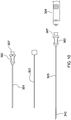
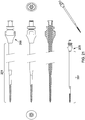
- Figs. 10-12 depict an exemplary delivery device directed to percutaneous intradiscal annular repair according to exemplary embodiments.
- This device is known as a "PIARES" device by the inventors, and is used for introducing therapeutics intradiscally, as described above.
- a device is inserted by hand, in most cases.
- the device is a two-needle device, and can have, for example, a first cannula/needle 301 , with a finger grip 362 and luer hub 307 at its proximal end.
- the cannula 301 can be, for example, 16 gauge (1.636 mm), and be approximately 3.5 inches (8.9 cm) long, for example, but such dimensions are exemplary and not limiting.
- a stylette 302 can fit within the cannula, of, for example, 21 gauge (0.813 mm) (for a 16 gauge (1.636 mm) cannula).
- the stylette 302 can lock onto the proximal end of the luer, at a luer lock hub 307 .
- the stylette 302 can remain in the outer needle 301 as a user inserts the device near a disc (but not all the way to the disc), then be removed so as to allow the insertion of the longer inner needle 303 , which can then penetrate into the disc, and can then, for example, be used to introduce therapeutics, for example, via a syringe 304 .
- Fig. 10 thus also shows, at the bottom of the figure, the second, or inner needle 303 of the device.
- This inner needle 303 fits inside the first needle/cannula 301 , and protrudes from it into the disc.
- the inner needle 303 can be, for example, 5 inches (12.7 cm) in length, where the bottom 20 mm or so have perforations 340 out of which the therapeutic agents can diffuse into the patient.
- Such a device can have, for example, a cannula of 21-25 gauge (0.813 mm to 0.508 mm). It can have a similar luer and finger grip 362 , and can similarly accept a syringe 304 which can lock on its luer lock hub 307 , to deliver the therapeutics, as described above. There is no stylette 302 for this inner needle, obviously.
- Fig. 11 depicts a variant embodiment of the exemplary PIARES delivery device of Fig. 10 , where instead of a luer lock hub at the proximal end of the inner needle 303 , a septum 309 is provided, thus completely isolating the delivery device and the disc into which the inner needle protrudes from exposure to the ambient space.
- a user inserts a needle into the septum 309 , in similar fashion as shown in Fig. 12 for the peripheral joint and spine embodiment of the delivery device.
- a user first inserts the outer needle 301 , with stylette 302 inside. This is done under imaging guidance, such as, for example, fluoroscopy or ultrasound.
- the outer needle 301 is placed near, but not all the way towards, the relevant disc.
- the stylette 302 is then removed, and the inner needle 303 inserted inside the outer needle.
- the outer needle 301 can be 16 gauge (1.636 mm), and the inner needle 303 from 21 to 25 gauge (0.81 mm to 0.508 mm), for example. Because it is longer than the outer needle 301 , for example, 5 inches (12.7 cm) versus 3.5 inches (8.9 cm), as shown in Figs.
- the inner needle 303 protrudes out the end of the outer needle 301 , and can be guided into the disc itself. Now at this point the distal end of the inner needle 303 touches the disc, but if the septum 309 embodiment of Fig. 11 is used on the inner needle 303 , the system is completely closed. Once intradiscal, therapeutic can be introduced via the inner needle 303 .
- the PIARES device has a number of advantages: (i) it provides a fully and completely closed system when the septum 309 is used on the inner needle's 303 proximal end; (ii) therapeutic can be delivered simultaneously to the nucleus and annulus of the disc, thus to deliver therapeutic to where the tear is; and (iii) by using the outer needle 301 for initial positioning, and then granularly positioning the longer inner needle, which is then fully set up to deliver therapeutic agents, trauma to the disc is minimized, as opposed to conventional approaches where needles are moved in and out. Less trauma means quicker healing and better disc repair.
- Fig. 12 depicts detailed views of an exemplary delivery device according to an embodiment directed to delivering therapeutics to bone-cartilage interfaces of peripheral joints and spine. It is a more detailed drawing of the exemplary device shown in exploded view at the top panel of Fig. 7 , with a perspective view. As seen in Fig. 12 , there can be a cutting tip 135 , and proximally from it external screw threads 130 between which are interspersed perforations 140 . Thus the grip 162 is first tapped with a hammer for initially setting it into place into dense cortical bone, and then subsequently twisted by a user to advance the delivery device into spongy bone (interior cancellous bone).
- the cannula 101 can be from 14 to 16 gauge (20.32 mm to 1.636 mm), for example, and at the proximal tip of the device there can be a needle pierceable septum seal 109 , for example, or a luer lock 107 with removable cap 160 such that a syringe can be attached, as shown in various other embodiments and as described above.
- an interface can be provided in the center of the end of the cap, to interface with commonly used drills, for example.
- Figs. 13-15 illustrate exemplary use of the device of Figs. 6-9 in knee procedures.
- Fig. 13 depicts an exemplary delivery device being inserted into the bone above and below an exemplary right knee.
- the device of Fig. 12 would be used. As can be seen in Fig. 13 , the device is generally inserted above and below the affected joint, and is inserted so as to be close to the interior edge of the cortical bone, above and below the cartilage of the affected joint. In the case of the knee joint depicted, one delivery device is inserted above and below the articular cartilage of the knee.
- the therapeutic introduced by the practitioner or user diffuses from the holes in the distal end of the cannula, and the bone marrow is stimulated by a GCSF to produce mesenchymal cells (MSC). As these cells come out of the bone marrow and make their way towards the BCI they get exposed to PRP before reaching the bone-cartilage interphase. The exposure to PRP is believed to thus induce the MSCs to become cartilage.
- MSC mesenchymal cells
- Fig. 14 depicts a magnified view of the knee joint, and adjacent tibia 198 and femur 199 as shown in Fig. 13 , further illustrating the diffusion of therapeutic(s) uniformly away from the cannula.
- Fig. 15 depicts details of the distal portion of the exemplary delivery device of Figs. 13-14 , showing the threads 130 and the holes 140 interspersed between them, at various rotational orientations of the delivery device 101 .
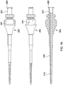
- Figs. 16-21 are detailed design drawings of an alternate improved delivery device tool according to an embodiment of the present invention. Variations of this device may , for example, be used in knee, hip and other joint procedures. This alternate delivery device is next described.
- exemplary prototype of the tool of Figs. 16-20 was fabricated, and tested on various patients with DJD of the knee with excellent results.
- the exemplary tool may be known and/or marketed under the trade name "PecaBoo.”
- Figs. 16-21 illustrate two versions of a delivery device according to embodiments of the present invention.
- Fig. 16(a) this is an overall view of the device.
- the device has three primary parts: a drill portion 201 , an impact cap 260 and an ergonomic tri-lobe handle 270 .
- the tri-lobe handle 270 is shown with its top and bottom views, respectively, in Fig. 16(b) .
- This metal portion 290 can be used once taken off the tool and turned around as a kind of a hammer, mallet or tapping device to push in the drill, when covered by the impact cap 260 , into a patient's bone.
- the impact cap 260 prevents damage to the hub 205 in such a use.
- Fig. 16(c) which is a longitudinal cross section of the tool
- the impact cap 260 which covers the luer 207 at the proximal end of the drill 201 as illustrated in more detail in the following figures. It is noted that in these figures the drill is referred to as "drill 16.”
- the "16" refers to an internal design identifier.
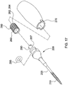
- FIG. 17 there is seen the drill 201 with integral hub 205 at 17(a), an O-ring 295 which slips over the hub 205 at 17(b), the impact cap 260 referred to above, at 17(c) and the tri-lobe handle 270 at 17(d). These fit together as shown, where the O-ring 295 is slipped over the top of the drill 201 with integral hub 205 so that it sits as shown in Fig. 16(c) . This then creates the tight slip fit of the tri-lobe handle 270 on the hub 205 .
- C clip rings can be used instead of an O-ring -- which would need to be replaced after some time - or, for example, other attachment mechanisms as may exist in the art.
- the impact cap 260 shown in Fig. 17(c) covers a female luer lock 207 such that the drill is totally closed and not exposed to the air any more than absolutely necessary.
- the impact cap 260 allows the tri-lobe handle 270 , as shown at 17(d), to be removed from the remainder of the tool and still allow the tool to be a completely closed system.
- a practitioner can, upon removing the tri-lobe handle 270 as noted above, turn it around such that the metal piece 290 built into the top of it can be used to tap on the impact cap 260 shown as Fig. 17(c) without damaging or affecting the rest of the tool, namely the drill with integral hub shown at Fig. 17(a) .
- the drill may be disposable and the handle reusable, or the entire device autoclavable and reusable.
- Fig. 18 illustrates the delivery tool of Figs. 16 and 17 in various longitudinal views and longitudinal cross section.
- the female locking luer 207 is shown at the far right as well as the integral hub 205 upon which, for example, an O-ring (as shown at Fig. 17(b) ) can be placed to provide a tight slip fit.
- Fig. 18(a) shows, for example, a 2.0 pitch helix to the cutting threads 230 and illustrates further that the tip of the drill 201 can be coated with a coating such as, for example, titanium nitride, or TiN.
- TiN is an extremely hard ceramic material which is often used as a coating on titanium allows, steel, carbide and aluminum components to improve the substrate surface properties.
- Fig. 18(b) illustrates the O-ring 295 gland, and an exemplary laser weld if the drill and hub are decided to be made in two pieces. Alternatively, they can be made in one piece and machined.
- Fig. 18(b) also illustrates how the drill 201 can be made of 455 stainless steel cannulated bar stock, for example. Other metals and stainless steel grades are also usable, in various exemplary embodiments.
- Fig. 18(c) also illustrates that the drill with integrated hub can be fabricated as one piece and that the tip of the drill has a straight portion, as well as a tapered portion occupying the most distal portion 210 of the delivery device, to make it more easily insertable into a patient.
- the tip of the drill has a straight portion, as well as a tapered portion occupying the most distal portion 210 of the delivery device, to make it more easily insertable into a patient.
- the tip of the device has a straight portion, as well as a tapered portion occupying the most distal portion 210 of the delivery device, to make it more easily insertable into a patient.
- the tip of the device has a straight portion, as well as a tapered portion occupying the most distal portion 210 of the delivery device, to make it more easily insertable into a patient.
- the tip can be laser welded to the cannulated drill portion, as shown in Fig. 18(c) .
- Fig. 18A is a copy of Fig. 18 somewhat magnified.
- perforations 240 in the distal tip 210 of the delivery device. These perforations are the holes by which the fluid is delivered.
- Fig. 18A there are thread cutting flutes 245 which are shown in a magnified depiction. These are, as described above, used to cut the bone as the drill is turned by a user as it is protruding into the patient's bone. Additionally, one can see the taper of the distal tip 210 as shown in Fig. 19, and Fig. 19 shows the fact that the tip itself can be laser welded all around to make sure that it is well fastened within the cannula. Fig. 18A also depicts an exemplary internal thread diameter --or minor diameter --of the threaded portion of the tool, as well as the external thread diameter -- also known as the major diameter. The tapered thread portion of the distal portion of the tip is illustrated in Fig. 18A .
- FIG. 18A illustrates the handle interface lug 281 by which the hub 205 may be attached to the handle, and further depict the threaded luer lock engagement key 280 by which occurs connects to the slots in the impact cap 260.
- the various portions proceeding from the proximal to the distal end of the drill are shown, from right to left, beginning with the female luer 207, the hub 205, the cannulated shaft 201, the center lumen, the threads 230, and the "spade" type cutting tip 235, 237.
- the attachment of the hub 205 to the cannulated shaft can be by welding all around or in two places, or, for example, the combination of hub and drill, i.e. the cannulated shaft, can be fabricated as one piece and formed by machining.
- Fig. 19 illustrates an overall exemplary dimensional relationship between the drill with integrated hub and the threaded distal portion thereof.
- the threads 230 can occupy approximately 30% of the overall length of the drill 201 with integrated hub 205 in one example.
- these dimensions are purely illustrative and various other dimensions and dimensional relationships can be implemented in various exemplary embodiments of the present invention, all within the scope of the present invention.
- Fig. 19 illustrates the drill 201 with integrated hub 205 without the impact cab cap 260 and without the handle 270.
- a section of the tip is labeled as "D" and that is presented in Fig. 19 in a greatly magnified view.
- This tip contains both the fluid side ports 240 by means of which therapeutics and/or liquids are dispensed into a patient using the delivery device 201, as well as various cutting features.
- There is a spade drill point 235 which has essentially a flat surface on two sides and cutting edges at the tip. This makes for much easier cutting than a fully cylindrical shape. Once the spade point 235 is inserted, when the user turns it creates a cylindrical bore.
- 16-19 is, as noted, capable of being slightly pounded or tapped into the bone of a patient above and below, for example, the knee joint or above and below, for example, a hip joint.
- a simply non-tapered cylinder it is much easier to penetrate the bone and then cut the bone as the device is turned. This easily creates a pathway for the drill to proceed through the bone to a point close the bone chondral interface. Therefore the combination of (i) the spade drill point 235 , (ii) the thread cutting flutes 245 , and (iii) the tapering of the drill tip 237 , all in combination allow for easy cutting of the bone surrounding the tip as a practitioner turns the drill such as, for example, by holding the tri-lobe handle shown in Fig. 17(d) , or, if she has sufficient strength, by simply twisting the integral hub 205 or the impact cap 260 . In alternate exemplary embodiments some or all of these features can be provided, but it need not always be necessary to have all of them.
- Fig. 20 illustrates details of the impact cap 260 .
- it can be made of 455 stainless steel bar stock, it can have a straight plunge cut so as to be able to be fastened on the female locking luer 207 as shown in Fig. 18 as well as in Fig. 17(a) , and it can have exemplary dimensions as shown, for example, or various other dimensions -- the ones shown being completely exemplary and illustrative.
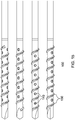
- Fig. 21 illustrates an elongated version of the 201 drill with integral hub 205 as shown in Fig. 18(c) for example.
- the overall length of the exemplary knee drill delivery tool is 104mm, but in the case of the exemplary hip embodiment shown in Fig. 21(d) , the overall length is 205mm, for example.
- Other relative dimensions are well within the scope of the present invention, it being generally understood that for most patients it takes a somewhat longer device to reach the hip than it does to reach the knee joint.
- exemplary dimensions of the hip-type drill shown in Figs. 21 and 22 as the drill, are shown in Figs. 21(a), 21(b), 21(c) and 21(d) .
- the device is essentially the same or similar to the exemplary knee version of Fig. 18 , except for the length of the drill itself, and in particular the length of the portion proceeding the tapers that is not threaded.
- the threaded portion as shown in Fig. 21(d) , can be, for example, the same as the knee delivery tool shown in Figs. 16-20 .
- Fig. 22 is a drawing of the hip delivery device super imposed on a coronal section of a human left hip joint and showing surrounding muscles and tissues.
- the numbers referred to in Fig. 22 are provided in the following Table for background and ease of locating where the drill is to be placed. As can be seen in the drawing, although this would not be done in practice, for ease of illustration, there is one drill shown in the proper position for the superior portion of the joint and one for the inferior portion of the joint, although obviously in practice these would generally be done sequentially and not at the same time.
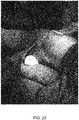
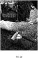
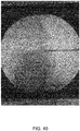
- Figs. 23-48 are photographs of exemplary actual procedures on human knees performed using the exemplary PecaBoo device described above. Procedures were done under fluoroscopic guidance, as noted above, and therefore both photographs of the patient's knees as well as some of the images from the fluoroscopy will be provided.
- Fig. 23 shows a practitioner initially inserting the PecaBoo device into a patient's knee close to the BCI, as described above.
- Fig. 24 shows the same patient where the practitioner has pushed the device significantly into the patient and is obviously inserting into the bone.
- Fig. 25 shows an even further protrusion of the device into the bone and that is its stopping place as shown in Fig. 26 .
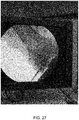
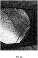
- Fig. 27 shows that the exemplary PecaBoo device has been screwed into the bone near the BCI below the knee joint itself.
- Fig. 28 is a close up of the image shown in Fig. 27 showing the same thing.
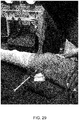
- Fig. 29 is the red ring of the exemplary O-ring remaining on the hub as shown in the expanded view of Fig. 17 , except here in Fig. 29 the O-ring is placed securely onto the hub which allows the tight fit of the yellow tri-lobe handle seen in Figs. 23 and 26 .
- Fig. 30 shows a close up of the view of Fig. 29 .
- Fig. 31 now shows the syringe, which had been attached in the views of Figs. 29 and 30 , being removed.
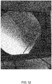
- a practitioner injects the medication into the patient in the set-up of Figs. 29 and 30 , he or she will often back out the exemplary PecaBoo delivery device so that the medication can be injected into the cavity left behind. This backing up and injecting may, for example, be repeated numerous times. Therefore, at the end of an injection, the exemplary delivery device will protrude less into the bone than it did at the beginning of the injection.
- Fig. 32 which shows the position of the protrusion of the device as shown in Fig. 31 into the bone which is less of a protrusion than that shown in Figs. 27 and 29 , after the initial screwing in of the delivery tool, as can readily be seen by comparison.
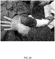
- Fig. 33 shows a view from the other end of the patient, i.e., looking upwards from the area of the patient's foot. This is a different patient than shown in the previous figures.
- the practitioner has just begun inserting an exemplary delivery device near the patient's knee joint in similar fashion as shown above. In this case, however, the exemplary delivery device is being inserted superior to the patient's knee on the femoral side.
- Fig. 34 shows a little bit of advance of the device and Fig. 35 shows it having been pushed in all the way such that the therapeutics can now be delivered after removal of the tri-lobe handle and the impact cap. This situation is seen in Fig. 36 , where syringes are being attached to the female luer of the device.
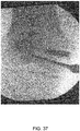
- Fig. 37 shows the protrusion of the exemplary device into the affected area on the femoral side of the joint. It is also noted in Fig. 37 that the patient has already had bone screw and other hardware inserted from prior procedures.
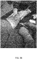
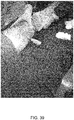
- Fig. 38 shows once again the device being inserted into the knee of a patient as described before, and Fig. 39 shows it having been protruded quite some distance into the patient's body which was necessary given the patient's tissue width.
- Fig. 40 shows the device under fluoroscopy into the bone superior to the knee joint corresponding with the view of Fig. 39 .
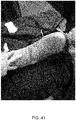
- Fig. 41 shows the same patient now being made ready for the injection, and
- Fig. 42 shows the injection using a syringe inserted into the female lure of the exemplary device.
- Fig. 43 is another image obtained from the fluoroscopic guidance as the practitioner was performing the injection.
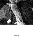
- Fig. 44 depicts another view of similar to that of Fig. 42 but from a different angle showing the device with the hub shown.
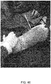
- Fig. 45 illustrates an injection into that same patient as does Fig. 46 when the injection has essentially been completed.
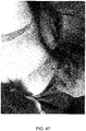
- Fig. 47 shows the beginning of an exemplary procedure where the device is first inserted into a patient
- Fig. 48 shows the fluoroscopic guidance where the distal tip of the drill is just penetrating the position inferior to the knee joint on the top of the tibia.
- Figs. 23-48 are merely exemplary and illustrate one example of the use of an delivery device according to the present invention with regard to patients with degenerated cartilage, or for example, edema resulting from an ischemia, in the knee joint.
- PIARES for joints, such as, the knee, for example, there may be female luer locks to minimize air exposure.
- the intradiscal system the same system may be used.
- a knee device such as PecaBoo
- PecaBoo may have female and male luer locks
- PIARES for intradiscal use may have a septum and be a fully closed system.
- all of PIARES, PecaBoo and other systems may be totally closed and use septums or the like.
- Kits may be provided with each type, or with one type, either closed system or male and female luer locks, or a given kit may mix and match. Exemplary delivery devices may also be sold separately.
- the drill and hub may be preferably fabricated in one piece without seams, but may also be provided in two pieces, as shown, with two pieces with a continuous 360 degree welded seam fully sealing around where the drill passes through the hub.
- One piece is often preferred for reasons of cost as well. It is noted that even when fabricated in one piece, in some embodiments the hardened tip may still need to be made separately and welded onto the distal end drill, as noted above.
- a surgical hand tool can be provided, used for the non-invasive placement and delivery of therapeutics, to a targeted site. This can be done through minimally invasive skin incision, or without any incision, as maybe desired.
- the delivery and placement of the therapeutic can be controlled and does not need a powered drill or guide wire.
- An exemplary device can have a closed pointed end, a threaded portion, and be provided with thread cutting/forming features, such as flute(s), and can have a shaft perforations to the central lumen at a distal end to deliver therapeutics or other preparations.
- means can be provided to attach a syringe in communication with the shaft's central lumen, and there may be a keyed engagement feature for attachment of a hand grip.
- the delivery device can be made of sufficient length to reach bone on either side of a desired or targeted joint, and to easily penetrate soft tissue and cortical bone to reach a targeted site in cancellous bone adjacent to a cartilage defect.
- the device's main shaft or drill portion can be made of hardened stainless steel, or the like, such as, for example, 400 series or 17-40 stainless steel, for example.
- the device can have, for example, an attachable/removable hand grip for ease of placement of the drill bit to a site, with a solid proximal end with which to tap or hammer, and with a grip for torquing the device through cortical bone and to guide a threaded shaft to a targeted site in cancellous bone, for example.
- the grip can have an ergonomic form for ease of use, such as a tri-lobe handle, which mimics the natural turn of a wrist in 120 degree increments.
- the device can have an impact cap to (i) provide impact anvil surface to protect a proximal luer during impaction, as well as to (ii) close the luer opening to a shaft lumen.
Landscapes
- Health & Medical Sciences (AREA)
- Life Sciences & Earth Sciences (AREA)
- Surgery (AREA)
- Engineering & Computer Science (AREA)
- Veterinary Medicine (AREA)
- Heart & Thoracic Surgery (AREA)
- Animal Behavior & Ethology (AREA)
- General Health & Medical Sciences (AREA)
- Public Health (AREA)
- Biomedical Technology (AREA)
- Medical Informatics (AREA)
- Molecular Biology (AREA)
- Orthopedic Medicine & Surgery (AREA)
- Pathology (AREA)
- Nuclear Medicine, Radiotherapy & Molecular Imaging (AREA)
- Hematology (AREA)
- Anesthesiology (AREA)
- Vascular Medicine (AREA)
- Dermatology (AREA)
- Surgical Instruments (AREA)
- Prostheses (AREA)
- Medicines That Contain Protein Lipid Enzymes And Other Medicines (AREA)
- Media Introduction/Drainage Providing Device (AREA)
- Infusion, Injection, And Reservoir Apparatuses (AREA)
Applications Claiming Priority (3)
| Application Number | Priority Date | Filing Date | Title |
|---|---|---|---|
| US201261686835P | 2012-04-11 | 2012-04-11 | |
| US201361800574P | 2013-03-15 | 2013-03-15 | |
| PCT/US2013/036259 WO2013155359A1 (en) | 2012-04-11 | 2013-04-11 | Cartilage repair, preservation and growth by stimulation of bone-chondral interphase and delivery system and related methods therefor |
Publications (3)
| Publication Number | Publication Date |
|---|---|
| EP2836147A1 EP2836147A1 (en) | 2015-02-18 |
| EP2836147A4 EP2836147A4 (en) | 2016-04-27 |
| EP2836147B1 true EP2836147B1 (en) | 2019-12-25 |
Family
ID=49328178
Family Applications (1)
| Application Number | Title | Priority Date | Filing Date |
|---|---|---|---|
| EP13775734.0A Active EP2836147B1 (en) | 2012-04-11 | 2013-04-11 | Delivery system for cartilage repair, preservation and growth by stimulation of bone-chondral interphase |
Country Status (15)
| Country | Link |
|---|---|
| US (5) | US9827010B2 (he) |
| EP (1) | EP2836147B1 (he) |
| JP (2) | JP2015519100A (he) |
| KR (1) | KR20150037738A (he) |
| CN (1) | CN104661606B (he) |
| AU (1) | AU2013245830A1 (he) |
| CA (1) | CA2870203A1 (he) |
| ES (1) | ES2772031T3 (he) |
| HK (1) | HK1207552A1 (he) |
| IL (1) | IL235156A0 (he) |
| IN (1) | IN2014DN09449A (he) |
| MX (1) | MX2014012205A (he) |
| NZ (1) | NZ701804A (he) |
| RU (1) | RU2014145346A (he) |
| WO (1) | WO2013155359A1 (he) |
Families Citing this family (6)
| Publication number | Priority date | Publication date | Assignee | Title |
|---|---|---|---|---|
| NZ701804A (en) * | 2012-04-11 | 2018-01-26 | Vad Scient Llc | Delivery device and system for cartilage repair, preservation and growth by stimulation of bone-chondral interface |
| CA3031434A1 (en) * | 2016-07-19 | 2018-01-25 | Avitus Orthopaedics, Inc. | Device for creating pilot hole to access cancellous bone |
| US10765453B2 (en) | 2017-04-18 | 2020-09-08 | Texas Scottish Rite Hospital For Children | Device and method for treating osteonecrosis |
| US10758253B2 (en) | 2017-04-18 | 2020-09-01 | Texas Scottish Rite Hospital For Children | Device and method for treating osteonecrosis |
| WO2019155434A1 (en) | 2018-02-09 | 2019-08-15 | Stemmatters, Biotecnologia e Medicina Regenerativa, S.A. | Medical device for the delivery of therapeutic formulations and methods of use thereof |
| JP7510481B2 (ja) | 2022-11-28 | 2024-07-03 | 財團法人金屬工業研究發展中心 | 手術器具 |
Family Cites Families (41)
| Publication number | Priority date | Publication date | Assignee | Title |
|---|---|---|---|---|
| US5601559A (en) * | 1988-10-24 | 1997-02-11 | Cook Incorporated | Intraosseous needle |
| US5484442A (en) | 1988-10-24 | 1996-01-16 | Cook Incorporated | Intraosseous needle |
| US4969870A (en) | 1989-06-07 | 1990-11-13 | The Regents Of The University Of California | Method and apparatus for intraosseous infusions |
| DE69116533T2 (de) * | 1990-12-13 | 1996-09-05 | Cook Inc., Bloomington, Ind. | Intraossale Nadel |
| DE4311715C2 (de) * | 1993-04-08 | 1996-02-01 | Fresenius Ag | Portkanüle |
| US6241734B1 (en) * | 1998-08-14 | 2001-06-05 | Kyphon, Inc. | Systems and methods for placing materials into bone |
| US6592588B1 (en) * | 1995-02-16 | 2003-07-15 | Arthrex, Inc. | Apparatus for osteochondral autograft transplantation |
| US5919196A (en) * | 1995-02-16 | 1999-07-06 | Arthrex, Inc. | Method and apparatus for osteochondral autograft transplantation |
| WO1998017190A2 (en) | 1996-10-23 | 1998-04-30 | Oratec Interventions, Inc. | Method and apparatus for treating intervertebral discs |
| US6468279B1 (en) | 1998-01-27 | 2002-10-22 | Kyphon Inc. | Slip-fit handle for hand-held instruments that access interior body regions |
| WO2000033909A1 (en) | 1998-12-09 | 2000-06-15 | Cook Incorporated | Hollow, curved, superelastic medical needle |
| US6210376B1 (en) * | 1999-04-08 | 2001-04-03 | New York University | Cannulated delivery pin |
| US7081122B1 (en) * | 1999-10-19 | 2006-07-25 | Kyphon Inc. | Hand-held instruments that access interior body regions |
| US6575919B1 (en) | 1999-10-19 | 2003-06-10 | Kyphon Inc. | Hand-held instruments that access interior body regions |
| EP1272131B1 (en) * | 2000-04-05 | 2006-03-01 | Kyphon Inc. | Devices for treating fractured and/or diseased bone |
| JP4058614B2 (ja) | 2001-08-09 | 2008-03-12 | 株式会社Jimro | 骨髄針 |
| CN2527232Y (zh) * | 2002-01-04 | 2002-12-25 | 中国人民解放军第一七四医院 | 颅内血肿粉碎穿刺针 |
| CN2540161Y (zh) * | 2002-03-13 | 2003-03-19 | 徐利浩 | 体腔穿刺针及留置导管 |
| US8808284B2 (en) * | 2008-09-26 | 2014-08-19 | Relievant Medsystems, Inc. | Systems for navigating an instrument through bone |
| US7699852B2 (en) * | 2003-11-19 | 2010-04-20 | Zimmer Spine, Inc. | Fenestrated bone tap and method |
| US7634823B2 (en) | 2004-03-26 | 2009-12-22 | Masco Corporation | Interface structure for a shower surround |
| US8657881B2 (en) | 2004-04-20 | 2014-02-25 | Depuy Mitek, Llc | Meniscal repair scaffold |
| WO2006076729A2 (en) * | 2005-01-14 | 2006-07-20 | Xtremi-T, Llc | Method and system for intraoperatively measuring and trimming the length of fracture fixation devices |
| CN101262825B (zh) * | 2005-07-07 | 2011-06-08 | 十字桅杆药品公司 | 骨间隙填充材料导入装置 |
| JP2007222472A (ja) | 2006-02-24 | 2007-09-06 | Nipro Corp | 薬剤微量投与具セット |
| CN201088612Y (zh) * | 2007-11-01 | 2008-07-23 | 杨子伟 | 多功能微创穿刺针 |
| WO2009086024A1 (en) * | 2007-12-19 | 2009-07-09 | Bassem Georgy | Device and method for orthopedic fracture fixation |
| EP2140823B1 (en) * | 2008-06-23 | 2015-08-26 | National Cancer Center | Pin assembly for operation |
| US8114112B2 (en) * | 2008-12-30 | 2012-02-14 | Cook Medical Technologies Llc | Stylet locking mechanism for medical delivery devices |
| US20120059380A1 (en) * | 2009-03-13 | 2012-03-08 | Wyeth Llc | Bone Cement Delivery Systems and Related Kits and Methods |
| EP2421453A2 (en) * | 2009-04-20 | 2012-02-29 | Osteo Innovations Llc | System and method for self filling bone screws |
| CN201426765Y (zh) | 2009-07-07 | 2010-03-24 | 张远成 | 骨端穿刺器 |
| US8574273B2 (en) | 2009-09-09 | 2013-11-05 | Innovision, Inc. | Bone screws and methods of use thereof |
| US20110112436A1 (en) * | 2009-11-06 | 2011-05-12 | SpineSmith Partners, LP | Distraction pins for fluid aspiration |
| WO2011063240A1 (en) * | 2009-11-20 | 2011-05-26 | Knee Creations, Llc | Implantable devices for subchondral treatment of joint pain |
| EP2544625B1 (en) * | 2010-03-10 | 2020-09-23 | Smith & Nephew, Inc. | Composite interference screws and drivers |
| US8758402B2 (en) * | 2010-12-17 | 2014-06-24 | Boston Scientific Scimed, Inc. | Tissue puncture closure device |
| US20120171179A1 (en) * | 2010-12-31 | 2012-07-05 | Jaewoo Pak | Apparatus, system, and method for compositions and methods for treating, preventing, or alleviating bone or cartilage diseases |
| EP2717808A2 (en) * | 2011-06-09 | 2014-04-16 | Zimmer GmbH | Instruments and devices for subchondral joint repair |
| AU2012323963B2 (en) * | 2011-10-13 | 2017-10-12 | Solventum Intellectual Properties Company | Stimulation of cartilage repair using reduced pressure treatment |
| NZ701804A (en) | 2012-04-11 | 2018-01-26 | Vad Scient Llc | Delivery device and system for cartilage repair, preservation and growth by stimulation of bone-chondral interface |
-
2013
- 2013-04-11 NZ NZ701804A patent/NZ701804A/en not_active IP Right Cessation
- 2013-04-11 CN CN201380030697.0A patent/CN104661606B/zh not_active Expired - Fee Related
- 2013-04-11 MX MX2014012205A patent/MX2014012205A/es unknown
- 2013-04-11 KR KR1020147031691A patent/KR20150037738A/ko not_active Application Discontinuation
- 2013-04-11 US US13/861,360 patent/US9827010B2/en active Active - Reinstated
- 2013-04-11 JP JP2015505925A patent/JP2015519100A/ja active Pending
- 2013-04-11 AU AU2013245830A patent/AU2013245830A1/en not_active Abandoned
- 2013-04-11 ES ES13775734T patent/ES2772031T3/es active Active
- 2013-04-11 EP EP13775734.0A patent/EP2836147B1/en active Active
- 2013-04-11 WO PCT/US2013/036259 patent/WO2013155359A1/en active Application Filing
- 2013-04-11 CA CA2870203A patent/CA2870203A1/en not_active Abandoned
- 2013-04-11 RU RU2014145346A patent/RU2014145346A/ru not_active Application Discontinuation
-
2014
- 2014-10-19 IL IL235156A patent/IL235156A0/he unknown
- 2014-11-11 IN IN9449DEN2014 patent/IN2014DN09449A/en unknown
-
2015
- 2015-08-27 HK HK15108338.7A patent/HK1207552A1/xx unknown
-
2017
- 2017-09-27 JP JP2017186176A patent/JP2018020153A/ja active Pending
- 2017-11-21 US US15/819,751 patent/US20180317962A1/en not_active Abandoned
-
2020
- 2020-04-29 US US16/862,448 patent/US11389196B2/en active Active
-
2022
- 2022-02-26 US US17/681,768 patent/US11759236B2/en active Active
-
2023
- 2023-09-18 US US18/369,325 patent/US20240000482A1/en active Pending
Non-Patent Citations (1)
| Title |
|---|
| None * |
Also Published As
| Publication number | Publication date |
|---|---|
| CN104661606A (zh) | 2015-05-27 |
| ES2772031T3 (es) | 2020-07-07 |
| US9827010B2 (en) | 2017-11-28 |
| RU2014145346A (ru) | 2016-06-10 |
| KR20150037738A (ko) | 2015-04-08 |
| WO2013155359A1 (en) | 2013-10-17 |
| US11759236B2 (en) | 2023-09-19 |
| EP2836147A4 (en) | 2016-04-27 |
| US20200253637A1 (en) | 2020-08-13 |
| US20180317962A1 (en) | 2018-11-08 |
| JP2018020153A (ja) | 2018-02-08 |
| EP2836147A1 (en) | 2015-02-18 |
| US20140088551A1 (en) | 2014-03-27 |
| US20220280191A1 (en) | 2022-09-08 |
| US20240000482A1 (en) | 2024-01-04 |
| HK1207552A1 (en) | 2016-02-05 |
| IL235156A0 (he) | 2014-12-31 |
| JP2015519100A (ja) | 2015-07-09 |
| CN104661606B (zh) | 2018-04-06 |
| MX2014012205A (es) | 2015-07-17 |
| NZ701804A (en) | 2018-01-26 |
| IN2014DN09449A (he) | 2015-07-17 |
| CA2870203A1 (en) | 2013-11-17 |
| AU2013245830A1 (en) | 2014-11-27 |
| US11389196B2 (en) | 2022-07-19 |
Similar Documents
| Publication | Publication Date | Title |
|---|---|---|
| US11759236B2 (en) | Cartilage repair, preservation and growth by stimulation of bone-chondral interface and delivery system and methods therefor | |
| US10271883B2 (en) | Method for treating joint pain and associated instruments | |
| AU775688B2 (en) | Apparatus and method for fixation of osteoporotic bone | |
| US10188440B2 (en) | Method and device for delivering medicine to bone | |
| EP2501342B1 (en) | Subchondral treatment of joint pain | |
| US9339294B2 (en) | Instruments for controlled delivery of injectable materials into bone | |
| US20110125157A1 (en) | Subchondral treatment of joint pain | |
| US10478199B2 (en) | Methods, systems, and devices for diagnosing and treating intervertebral disc degeneration | |
| US20120059380A1 (en) | Bone Cement Delivery Systems and Related Kits and Methods | |
| JP2015519100A5 (he) | ||
| US20150018754A1 (en) | Devices, compositions and methods for treating acute and chronic tissue damage |
Legal Events
| Date | Code | Title | Description |
|---|---|---|---|
| PUAI | Public reference made under article 153(3) epc to a published international application that has entered the european phase |
Free format text: ORIGINAL CODE: 0009012 |
|
| 17P | Request for examination filed |
Effective date: 20141110 |
|
| AK | Designated contracting states |
Kind code of ref document: A1 Designated state(s): AL AT BE BG CH CY CZ DE DK EE ES FI FR GB GR HR HU IE IS IT LI LT LU LV MC MK MT NL NO PL PT RO RS SE SI SK SM TR |
|
| AX | Request for extension of the european patent |
Extension state: BA ME |
|
| DAX | Request for extension of the european patent (deleted) | ||
| RIC1 | Information provided on ipc code assigned before grant |
Ipc: A61B 17/34 20060101AFI20151201BHEP Ipc: A61B 17/00 20060101ALN20151201BHEP Ipc: A61M 5/158 20060101ALN20151201BHEP |
|
| RA4 | Supplementary search report drawn up and despatched (corrected) |
Effective date: 20160324 |
|
| RIC1 | Information provided on ipc code assigned before grant |
Ipc: A61B 17/00 20060101ALN20160318BHEP Ipc: A61B 17/34 20060101AFI20160318BHEP Ipc: A61M 5/158 20060101ALN20160318BHEP |
|
| STAA | Information on the status of an ep patent application or granted ep patent |
Free format text: STATUS: REQUEST FOR EXAMINATION WAS MADE |
|
| STAA | Information on the status of an ep patent application or granted ep patent |
Free format text: STATUS: EXAMINATION IS IN PROGRESS |
|
| 17Q | First examination report despatched |
Effective date: 20171010 |
|
| REG | Reference to a national code |
Ref country code: DE Ref legal event code: R079 Ref document number: 602013064374 Country of ref document: DE Free format text: PREVIOUS MAIN CLASS: A61B0017560000 Ipc: A61B0017340000 |
|
| GRAP | Despatch of communication of intention to grant a patent |
Free format text: ORIGINAL CODE: EPIDOSNIGR1 |
|
| STAA | Information on the status of an ep patent application or granted ep patent |
Free format text: STATUS: GRANT OF PATENT IS INTENDED |
|
| RIC1 | Information provided on ipc code assigned before grant |
Ipc: A61B 17/34 20060101AFI20190603BHEP Ipc: A61M 5/158 20060101ALN20190603BHEP |
|
| RIC1 | Information provided on ipc code assigned before grant |
Ipc: A61B 17/34 20060101AFI20190617BHEP Ipc: A61M 5/158 20060101ALN20190617BHEP |
|
| INTG | Intention to grant announced |
Effective date: 20190705 |
|
| GRAS | Grant fee paid |
Free format text: ORIGINAL CODE: EPIDOSNIGR3 |
|
| GRAA | (expected) grant |
Free format text: ORIGINAL CODE: 0009210 |
|
| STAA | Information on the status of an ep patent application or granted ep patent |
Free format text: STATUS: THE PATENT HAS BEEN GRANTED |
|
| AK | Designated contracting states |
Kind code of ref document: B1 Designated state(s): AL AT BE BG CH CY CZ DE DK EE ES FI FR GB GR HR HU IE IS IT LI LT LU LV MC MK MT NL NO PL PT RO RS SE SI SK SM TR |
|
| REG | Reference to a national code |
Ref country code: GB Ref legal event code: FG4D |
|
| REG | Reference to a national code |
Ref country code: CH Ref legal event code: EP |
|
| REG | Reference to a national code |
Ref country code: AT Ref legal event code: REF Ref document number: 1216263 Country of ref document: AT Kind code of ref document: T Effective date: 20200115 |
|
| REG | Reference to a national code |
Ref country code: DE Ref legal event code: R096 Ref document number: 602013064374 Country of ref document: DE |
|
| REG | Reference to a national code |
Ref country code: IE Ref legal event code: FG4D |
|
| REG | Reference to a national code |
Ref country code: SE Ref legal event code: TRGR |
|
| REG | Reference to a national code |
Ref country code: CH Ref legal event code: NV Representative=s name: VALIPAT S.A. C/O BOVARD SA NEUCHATEL, CH |
|
| REG | Reference to a national code |
Ref country code: NL Ref legal event code: MP Effective date: 20191225 |
|
| PG25 | Lapsed in a contracting state [announced via postgrant information from national office to epo] |
Ref country code: LT Free format text: LAPSE BECAUSE OF FAILURE TO SUBMIT A TRANSLATION OF THE DESCRIPTION OR TO PAY THE FEE WITHIN THE PRESCRIBED TIME-LIMIT Effective date: 20191225 Ref country code: GR Free format text: LAPSE BECAUSE OF FAILURE TO SUBMIT A TRANSLATION OF THE DESCRIPTION OR TO PAY THE FEE WITHIN THE PRESCRIBED TIME-LIMIT Effective date: 20200326 Ref country code: FI Free format text: LAPSE BECAUSE OF FAILURE TO SUBMIT A TRANSLATION OF THE DESCRIPTION OR TO PAY THE FEE WITHIN THE PRESCRIBED TIME-LIMIT Effective date: 20191225 Ref country code: BG Free format text: LAPSE BECAUSE OF FAILURE TO SUBMIT A TRANSLATION OF THE DESCRIPTION OR TO PAY THE FEE WITHIN THE PRESCRIBED TIME-LIMIT Effective date: 20200325 Ref country code: NO Free format text: LAPSE BECAUSE OF FAILURE TO SUBMIT A TRANSLATION OF THE DESCRIPTION OR TO PAY THE FEE WITHIN THE PRESCRIBED TIME-LIMIT Effective date: 20200325 Ref country code: LV Free format text: LAPSE BECAUSE OF FAILURE TO SUBMIT A TRANSLATION OF THE DESCRIPTION OR TO PAY THE FEE WITHIN THE PRESCRIBED TIME-LIMIT Effective date: 20191225 |
|
| REG | Reference to a national code |
Ref country code: LT Ref legal event code: MG4D |
|
| PG25 | Lapsed in a contracting state [announced via postgrant information from national office to epo] |
Ref country code: HR Free format text: LAPSE BECAUSE OF FAILURE TO SUBMIT A TRANSLATION OF THE DESCRIPTION OR TO PAY THE FEE WITHIN THE PRESCRIBED TIME-LIMIT Effective date: 20191225 Ref country code: RS Free format text: LAPSE BECAUSE OF FAILURE TO SUBMIT A TRANSLATION OF THE DESCRIPTION OR TO PAY THE FEE WITHIN THE PRESCRIBED TIME-LIMIT Effective date: 20191225 |
|
| PG25 | Lapsed in a contracting state [announced via postgrant information from national office to epo] |
Ref country code: AL Free format text: LAPSE BECAUSE OF FAILURE TO SUBMIT A TRANSLATION OF THE DESCRIPTION OR TO PAY THE FEE WITHIN THE PRESCRIBED TIME-LIMIT Effective date: 20191225 |
|
| REG | Reference to a national code |
Ref country code: ES Ref legal event code: FG2A Ref document number: 2772031 Country of ref document: ES Kind code of ref document: T3 Effective date: 20200707 |
|
| PG25 | Lapsed in a contracting state [announced via postgrant information from national office to epo] |
Ref country code: PT Free format text: LAPSE BECAUSE OF FAILURE TO SUBMIT A TRANSLATION OF THE DESCRIPTION OR TO PAY THE FEE WITHIN THE PRESCRIBED TIME-LIMIT Effective date: 20200520 Ref country code: CZ Free format text: LAPSE BECAUSE OF FAILURE TO SUBMIT A TRANSLATION OF THE DESCRIPTION OR TO PAY THE FEE WITHIN THE PRESCRIBED TIME-LIMIT Effective date: 20191225 Ref country code: RO Free format text: LAPSE BECAUSE OF FAILURE TO SUBMIT A TRANSLATION OF THE DESCRIPTION OR TO PAY THE FEE WITHIN THE PRESCRIBED TIME-LIMIT Effective date: 20191225 Ref country code: EE Free format text: LAPSE BECAUSE OF FAILURE TO SUBMIT A TRANSLATION OF THE DESCRIPTION OR TO PAY THE FEE WITHIN THE PRESCRIBED TIME-LIMIT Effective date: 20191225 Ref country code: NL Free format text: LAPSE BECAUSE OF FAILURE TO SUBMIT A TRANSLATION OF THE DESCRIPTION OR TO PAY THE FEE WITHIN THE PRESCRIBED TIME-LIMIT Effective date: 20191225 |
|
| PG25 | Lapsed in a contracting state [announced via postgrant information from national office to epo] |
Ref country code: SM Free format text: LAPSE BECAUSE OF FAILURE TO SUBMIT A TRANSLATION OF THE DESCRIPTION OR TO PAY THE FEE WITHIN THE PRESCRIBED TIME-LIMIT Effective date: 20191225 Ref country code: SK Free format text: LAPSE BECAUSE OF FAILURE TO SUBMIT A TRANSLATION OF THE DESCRIPTION OR TO PAY THE FEE WITHIN THE PRESCRIBED TIME-LIMIT Effective date: 20191225 Ref country code: IS Free format text: LAPSE BECAUSE OF FAILURE TO SUBMIT A TRANSLATION OF THE DESCRIPTION OR TO PAY THE FEE WITHIN THE PRESCRIBED TIME-LIMIT Effective date: 20200425 |
|
| REG | Reference to a national code |
Ref country code: DE Ref legal event code: R097 Ref document number: 602013064374 Country of ref document: DE |
|
| PG25 | Lapsed in a contracting state [announced via postgrant information from national office to epo] |
Ref country code: DK Free format text: LAPSE BECAUSE OF FAILURE TO SUBMIT A TRANSLATION OF THE DESCRIPTION OR TO PAY THE FEE WITHIN THE PRESCRIBED TIME-LIMIT Effective date: 20191225 |
|
| PLBE | No opposition filed within time limit |
Free format text: ORIGINAL CODE: 0009261 |
|
| STAA | Information on the status of an ep patent application or granted ep patent |
Free format text: STATUS: NO OPPOSITION FILED WITHIN TIME LIMIT |
|
| PG25 | Lapsed in a contracting state [announced via postgrant information from national office to epo] |
Ref country code: MC Free format text: LAPSE BECAUSE OF FAILURE TO SUBMIT A TRANSLATION OF THE DESCRIPTION OR TO PAY THE FEE WITHIN THE PRESCRIBED TIME-LIMIT Effective date: 20191225 Ref country code: SI Free format text: LAPSE BECAUSE OF FAILURE TO SUBMIT A TRANSLATION OF THE DESCRIPTION OR TO PAY THE FEE WITHIN THE PRESCRIBED TIME-LIMIT Effective date: 20191225 |
|
| REG | Reference to a national code |
Ref country code: CH Ref legal event code: PL |
|
| 26N | No opposition filed |
Effective date: 20200928 |
|
| PG25 | Lapsed in a contracting state [announced via postgrant information from national office to epo] |
Ref country code: CH Free format text: LAPSE BECAUSE OF NON-PAYMENT OF DUE FEES Effective date: 20200430 Ref country code: LU Free format text: LAPSE BECAUSE OF NON-PAYMENT OF DUE FEES Effective date: 20200411 Ref country code: LI Free format text: LAPSE BECAUSE OF NON-PAYMENT OF DUE FEES Effective date: 20200430 Ref country code: SE Free format text: LAPSE BECAUSE OF NON-PAYMENT OF DUE FEES Effective date: 20200412 |
|
| REG | Reference to a national code |
Ref country code: BE Ref legal event code: MM Effective date: 20200430 |
|
| PG25 | Lapsed in a contracting state [announced via postgrant information from national office to epo] |
Ref country code: PL Free format text: LAPSE BECAUSE OF FAILURE TO SUBMIT A TRANSLATION OF THE DESCRIPTION OR TO PAY THE FEE WITHIN THE PRESCRIBED TIME-LIMIT Effective date: 20191225 Ref country code: BE Free format text: LAPSE BECAUSE OF NON-PAYMENT OF DUE FEES Effective date: 20200430 |
|
| PG25 | Lapsed in a contracting state [announced via postgrant information from national office to epo] |
Ref country code: IE Free format text: LAPSE BECAUSE OF NON-PAYMENT OF DUE FEES Effective date: 20200411 |
|
| REG | Reference to a national code |
Ref country code: AT Ref legal event code: MM01 Ref document number: 1216263 Country of ref document: AT Kind code of ref document: T Effective date: 20200411 |
|
| PG25 | Lapsed in a contracting state [announced via postgrant information from national office to epo] |
Ref country code: AT Free format text: LAPSE BECAUSE OF NON-PAYMENT OF DUE FEES Effective date: 20200411 |
|
| REG | Reference to a national code |
Ref country code: ES Ref legal event code: FD2A Effective date: 20210831 |
|
| PG25 | Lapsed in a contracting state [announced via postgrant information from national office to epo] |
Ref country code: IT Free format text: LAPSE BECAUSE OF NON-PAYMENT OF DUE FEES Effective date: 20200411 |
|
| PG25 | Lapsed in a contracting state [announced via postgrant information from national office to epo] |
Ref country code: ES Free format text: LAPSE BECAUSE OF NON-PAYMENT OF DUE FEES Effective date: 20200412 |
|
| REG | Reference to a national code |
Ref country code: AT Ref legal event code: UEP Ref document number: 1216263 Country of ref document: AT Kind code of ref document: T Effective date: 20191225 |
|
| PG25 | Lapsed in a contracting state [announced via postgrant information from national office to epo] |
Ref country code: MT Free format text: LAPSE BECAUSE OF FAILURE TO SUBMIT A TRANSLATION OF THE DESCRIPTION OR TO PAY THE FEE WITHIN THE PRESCRIBED TIME-LIMIT Effective date: 20191225 Ref country code: CY Free format text: LAPSE BECAUSE OF FAILURE TO SUBMIT A TRANSLATION OF THE DESCRIPTION OR TO PAY THE FEE WITHIN THE PRESCRIBED TIME-LIMIT Effective date: 20191225 |
|
| PG25 | Lapsed in a contracting state [announced via postgrant information from national office to epo] |
Ref country code: MK Free format text: LAPSE BECAUSE OF FAILURE TO SUBMIT A TRANSLATION OF THE DESCRIPTION OR TO PAY THE FEE WITHIN THE PRESCRIBED TIME-LIMIT Effective date: 20191225 |
|
| PGFP | Annual fee paid to national office [announced via postgrant information from national office to epo] |
Ref country code: FR Payment date: 20220408 Year of fee payment: 10 |
|
| PG25 | Lapsed in a contracting state [announced via postgrant information from national office to epo] |
Ref country code: FR Free format text: LAPSE BECAUSE OF NON-PAYMENT OF DUE FEES Effective date: 20230430 |
|
| PGFP | Annual fee paid to national office [announced via postgrant information from national office to epo] |
Ref country code: GB Payment date: 20240221 Year of fee payment: 12 |
|
| PGFP | Annual fee paid to national office [announced via postgrant information from national office to epo] |
Ref country code: TR Payment date: 20240325 Year of fee payment: 12 |
|
| PGFP | Annual fee paid to national office [announced via postgrant information from national office to epo] |
Ref country code: DE Payment date: 20240418 Year of fee payment: 12 |