EP2835708A2 - Method and system for remotely controlling a vehicle - Google Patents
Method and system for remotely controlling a vehicle Download PDFInfo
- Publication number
- EP2835708A2 EP2835708A2 EP20140180084 EP14180084A EP2835708A2 EP 2835708 A2 EP2835708 A2 EP 2835708A2 EP 20140180084 EP20140180084 EP 20140180084 EP 14180084 A EP14180084 A EP 14180084A EP 2835708 A2 EP2835708 A2 EP 2835708A2
- Authority
- EP
- European Patent Office
- Prior art keywords
- location
- vehicle
- set forth
- vector
- onboard
- Prior art date
- Legal status (The legal status is an assumption and is not a legal conclusion. Google has not performed a legal analysis and makes no representation as to the accuracy of the status listed.)
- Ceased
Links
- 238000000034 method Methods 0.000 title claims abstract description 44
- 238000005259 measurement Methods 0.000 claims abstract description 22
- 230000005670 electromagnetic radiation Effects 0.000 claims abstract description 17
- 230000003595 spectral effect Effects 0.000 claims description 15
- 230000001419 dependent effect Effects 0.000 claims 1
- 238000012790 confirmation Methods 0.000 abstract description 2
- 230000001010 compromised effect Effects 0.000 description 2
- 230000006870 function Effects 0.000 description 2
- 238000010586 diagram Methods 0.000 description 1
- 230000003287 optical effect Effects 0.000 description 1
- 230000000007 visual effect Effects 0.000 description 1
Images


Classifications
-
- G—PHYSICS
- G01—MEASURING; TESTING
- G01S—RADIO DIRECTION-FINDING; RADIO NAVIGATION; DETERMINING DISTANCE OR VELOCITY BY USE OF RADIO WAVES; LOCATING OR PRESENCE-DETECTING BY USE OF THE REFLECTION OR RERADIATION OF RADIO WAVES; ANALOGOUS ARRANGEMENTS USING OTHER WAVES
- G01S19/00—Satellite radio beacon positioning systems; Determining position, velocity or attitude using signals transmitted by such systems
- G01S19/01—Satellite radio beacon positioning systems transmitting time-stamped messages, e.g. GPS [Global Positioning System], GLONASS [Global Orbiting Navigation Satellite System] or GALILEO
- G01S19/13—Receivers
- G01S19/21—Interference related issues ; Issues related to cross-correlation, spoofing or other methods of denial of service
- G01S19/215—Interference related issues ; Issues related to cross-correlation, spoofing or other methods of denial of service issues related to spoofing
-
- G—PHYSICS
- G05—CONTROLLING; REGULATING
- G05D—SYSTEMS FOR CONTROLLING OR REGULATING NON-ELECTRIC VARIABLES
- G05D1/00—Control of position, course, altitude or attitude of land, water, air or space vehicles, e.g. using automatic pilots
- G05D1/0011—Control of position, course, altitude or attitude of land, water, air or space vehicles, e.g. using automatic pilots associated with a remote control arrangement
-
- G—PHYSICS
- G01—MEASURING; TESTING
- G01C—MEASURING DISTANCES, LEVELS OR BEARINGS; SURVEYING; NAVIGATION; GYROSCOPIC INSTRUMENTS; PHOTOGRAMMETRY OR VIDEOGRAMMETRY
- G01C21/00—Navigation; Navigational instruments not provided for in groups G01C1/00 - G01C19/00
- G01C21/10—Navigation; Navigational instruments not provided for in groups G01C1/00 - G01C19/00 by using measurements of speed or acceleration
- G01C21/12—Navigation; Navigational instruments not provided for in groups G01C1/00 - G01C19/00 by using measurements of speed or acceleration executed aboard the object being navigated; Dead reckoning
- G01C21/16—Navigation; Navigational instruments not provided for in groups G01C1/00 - G01C19/00 by using measurements of speed or acceleration executed aboard the object being navigated; Dead reckoning by integrating acceleration or speed, i.e. inertial navigation
- G01C21/165—Navigation; Navigational instruments not provided for in groups G01C1/00 - G01C19/00 by using measurements of speed or acceleration executed aboard the object being navigated; Dead reckoning by integrating acceleration or speed, i.e. inertial navigation combined with non-inertial navigation instruments
- G01C21/1656—Navigation; Navigational instruments not provided for in groups G01C1/00 - G01C19/00 by using measurements of speed or acceleration executed aboard the object being navigated; Dead reckoning by integrating acceleration or speed, i.e. inertial navigation combined with non-inertial navigation instruments with passive imaging devices, e.g. cameras
-
- G—PHYSICS
- G01—MEASURING; TESTING
- G01C—MEASURING DISTANCES, LEVELS OR BEARINGS; SURVEYING; NAVIGATION; GYROSCOPIC INSTRUMENTS; PHOTOGRAMMETRY OR VIDEOGRAMMETRY
- G01C21/00—Navigation; Navigational instruments not provided for in groups G01C1/00 - G01C19/00
- G01C21/10—Navigation; Navigational instruments not provided for in groups G01C1/00 - G01C19/00 by using measurements of speed or acceleration
- G01C21/12—Navigation; Navigational instruments not provided for in groups G01C1/00 - G01C19/00 by using measurements of speed or acceleration executed aboard the object being navigated; Dead reckoning
- G01C21/16—Navigation; Navigational instruments not provided for in groups G01C1/00 - G01C19/00 by using measurements of speed or acceleration executed aboard the object being navigated; Dead reckoning by integrating acceleration or speed, i.e. inertial navigation
- G01C21/183—Compensation of inertial measurements, e.g. for temperature effects
- G01C21/188—Compensation of inertial measurements, e.g. for temperature effects for accumulated errors, e.g. by coupling inertial systems with absolute positioning systems
-
- G—PHYSICS
- G01—MEASURING; TESTING
- G01S—RADIO DIRECTION-FINDING; RADIO NAVIGATION; DETERMINING DISTANCE OR VELOCITY BY USE OF RADIO WAVES; LOCATING OR PRESENCE-DETECTING BY USE OF THE REFLECTION OR RERADIATION OF RADIO WAVES; ANALOGOUS ARRANGEMENTS USING OTHER WAVES
- G01S19/00—Satellite radio beacon positioning systems; Determining position, velocity or attitude using signals transmitted by such systems
- G01S19/01—Satellite radio beacon positioning systems transmitting time-stamped messages, e.g. GPS [Global Positioning System], GLONASS [Global Orbiting Navigation Satellite System] or GALILEO
- G01S19/13—Receivers
- G01S19/21—Interference related issues ; Issues related to cross-correlation, spoofing or other methods of denial of service
-
- G—PHYSICS
- G05—CONTROLLING; REGULATING
- G05D—SYSTEMS FOR CONTROLLING OR REGULATING NON-ELECTRIC VARIABLES
- G05D1/00—Control of position, course, altitude or attitude of land, water, air or space vehicles, e.g. using automatic pilots
- G05D1/0055—Control of position, course, altitude or attitude of land, water, air or space vehicles, e.g. using automatic pilots with safety arrangements
- G05D1/0077—Control of position, course, altitude or attitude of land, water, air or space vehicles, e.g. using automatic pilots with safety arrangements using redundant signals or controls
-
- G—PHYSICS
- G01—MEASURING; TESTING
- G01S—RADIO DIRECTION-FINDING; RADIO NAVIGATION; DETERMINING DISTANCE OR VELOCITY BY USE OF RADIO WAVES; LOCATING OR PRESENCE-DETECTING BY USE OF THE REFLECTION OR RERADIATION OF RADIO WAVES; ANALOGOUS ARRANGEMENTS USING OTHER WAVES
- G01S19/00—Satellite radio beacon positioning systems; Determining position, velocity or attitude using signals transmitted by such systems
- G01S19/01—Satellite radio beacon positioning systems transmitting time-stamped messages, e.g. GPS [Global Positioning System], GLONASS [Global Orbiting Navigation Satellite System] or GALILEO
- G01S19/13—Receivers
-
- G—PHYSICS
- G05—CONTROLLING; REGULATING
- G05D—SYSTEMS FOR CONTROLLING OR REGULATING NON-ELECTRIC VARIABLES
- G05D1/00—Control of position, course, altitude or attitude of land, water, air or space vehicles, e.g. using automatic pilots
-
- G—PHYSICS
- G05—CONTROLLING; REGULATING
- G05D—SYSTEMS FOR CONTROLLING OR REGULATING NON-ELECTRIC VARIABLES
- G05D1/00—Control of position, course, altitude or attitude of land, water, air or space vehicles, e.g. using automatic pilots
- G05D1/0055—Control of position, course, altitude or attitude of land, water, air or space vehicles, e.g. using automatic pilots with safety arrangements
Definitions
- the invention relates to controlling a vehicle remotely. More particularly, the invention relates to a method and system for ensuring proper control of a vehicle while the vehicle is being operated in environments where standard positioning technology of the vehicle is unavailable and/or unreliable. The system will then remain in control until after it is confirmed that the normal positioning technology operation of the vehicle has been restored.
- UAVs Unmanned Air Vehicles
- the UAVs are guided by telemetry and, as the name purports, they are unmanned. UAVs are often referred to as drones.
- UAVs One problem associated with UAVs is the situation in which the control system for the UAV is inappropriately accessed and manipulated in order to control the system and/or operate in a manner that prevents it from completing its mission as planned. In some instances, the UAV will be instructed to land in hostile territory. In other situations, the UAV may identify a target that is not the designated target for the mission in which the UAV is operating. Generally, such "spoofing" occurs when counterfeit GPS signals are sent to the UAV causing it to steer off course or have it operate in a manner other than what was previously designated in its mission.
- a method for determining the physical location of a vehicle being guided with an onboard navigational positioning system capable of detecting and generating a positioning location vector for the vehicle includes the steps of detecting and receiving a plurality of electromagnetic radiation signals. A plurality of ambient parameter measurements is also received. A confirming location position is calculated from the plurality of electromagnetic radiation signals and the plurality of ambient parameter measurements. The confirming location position is compared to the positioning location vector generated by the onboard system to create a differential vector. If the confirmation location position and the positioning location vector are greater than a predetermined value, the positioning location vector generated by the onboard navigational positioning system is prevented from being used in directing the movement of the vehicle until the position differential is below a predetermined error value.
- a method for determining a physical location of a vehicle being guided with an onboard navigational positioning system capable of generating a location vector for a vehicle comprising the steps of: receiving a plurality of electrical signals; calculating a confirming location position from the plurality of electrical signals; comparing the confirming location position to the location vector to create a position differential; and preventing use of the location vector in directing movement of the vehicle until the position differential is below a predetermined error value.
- the plurality of electrical signals includes a plurality of electromagnetic radiation signals.
- the plurality of electrical signals further includes a plurality of ambient parameter measurements.
- each signal of the plurality of electromagnetic radiation signals is from a plurality of spectral ranges.
- the spectral ranges are broadband and encompass multiple spectral ranges.
- the method further includes the step of determining the location and direction of the vehicle by matching the confirming location vector to ephemeris data.
- the step of comparing includes combinatorial hashing of the ambient parameter measurements.
- the step of comparing includes the use of ephemeris data.
- the method includes the use of an onboard digital compass.
- the method includes the use of an onboard three - axis gyroscope.
- the method includes the use of an onboard accelerometer.
- the method includes the use of an onboard ambient light sensor.
- the method includes the step of repeating the step of comparing the confirming location position to the GPS location position throughout a time period the vehicle is moving.
- a method for determining a physical location of a vehicle being guided with an onboard navigational positioning system capable of generating a location vector for a vehicle comprising the steps of: receiving a plurality of electromagnetic radiation signals; receiving a plurality of ambient parameter measurements; measuring the time at which each of the plurality of ambient parameter measurements are made; calculating a confirming location position from the time measurement, the plurality of electromagnetic radiation signals and the plurality of ambient parameter measurements; comparing the confirming location position to the location vector to create a differential vector; and preventing use of the onboard navigational positioning system in directing movement of the vehicle until the differential vector is below a predetermined error value.
- each signal of the plurality of electromagnetic radiation signals is from a plurality of spectral ranges.
- the spectral ranges are broadband and encompass multiple spectral ranges.
- the method includes the step of determining the location and direction of the vehicle by matching the confirming location vector to ephemeris data.
- the step of comparing includes combinatorial hashing of the ambient parameter measurements.
- step of comparing includes the use of ephemeris data.
- the method includes the use of an onboard digital compass.
- Unmanned vehicles, aircraft and watercraft require accurate navigational systems in order for them to operate as designed. If the navigational systems fail, or if the navigational systems are interfered with and compromised, the host vehicle quickly becomes a liability because it will either be a participant in an accident or it will be retrieved by someone other than the owner.
- UAV unmanned air vehicle
- the UAV 10 identifies its position with respect to the earth 12 using an onboard navigational positioning system, such as the global positioning system GPS, graphically represented by satellites 14.
- GPS global positioning system
- the UAV 10 also receives commands from a ground command base 16.
- a ground command base 16 As one skilled in the art will appreciate, the UAV 10 is vulnerable should the GPS 14 provide inaccurate data or no data and when another ground base similar to the command ground base 16 transmits signals to the UAV 10 to effectively change the mission or direction of the UAV 10. In such situations, the UAV 10 may be directed to land in a hostile territory or it may deploy its payload at a "spoofed" target other than the designated target for the mission of the UAV 10.
- a redundant system passively checks the location of the UAV 10 and compares it to the data being received by the GPS 14.
- the UAV 10 receives data in the form of electrical signals from an onboard compass 18, a three-axis gyroscope 20, and ground based radio transmitters 22.
- Sources of electrical signals may also include the ground based radio transmitters 22, which may provide a plurality of electromagnetic radiation signals from a plurality of spectral ranges.
- the spectral ranges are broadband and encompass multiple spectral ranges.
- ground based radio transmitters 22 include, but are not limited to, television broadcast signals, radio broadcast signals, cell tower transmitters, and the like.
- FIG 3 the compass 18, three-axis gyroscope 20, and ground based radio transmitters 22 are graphically represented.
- a microwave transmitting tower 24 is also shown to provide an input, although this may also be categorized with the generally ground based radio transmitter 22.
- An additional input of visual data is illustrated in Figure 3 graphically by a camera 26. All of the data provided by each of these input devices 18, 20, 22, 24, 26 help define a target zone 28. Using the data located within the target zone 28, an anchor point 30 may be identified as the position of the UAV 10.
- the system may use combinatorial hashing using the inputs collected by the input devices 18, 20, 22, 24, 26 to identify the anchor point 30, which is the location of the UAV 10. This is done independently of the primary navigational system, the GPS 14.
- one embodiment may include the use of at least two cameras, presumably one at either end of a wing tip of the UAV 10.
- Euclidean geometry one could calculate the distance between the UAV 10 and an object which is at the focal point of both cameras 26.
- Use of the cameras 26 and an antennae system 32 onboard the UAV 10 is also used to identify the direction and location of the UAV 10 by collecting the combinatorial hash in a manner that allows the vector hash to be compared to positional data stored in an ephemerid location data base 34 on board the UAV 10.
- a calculation may be made using the ephemerides to determine a particular location and direction in which the UAV 10 currently is operating.
- the ephemerid information will be automatically reviewed quickly and accurately to identify the location and direction of the UAV 10.
- the combinatorial hashing will occur in parallel calculations due to the different types of ephemerides available for the calculation.
- data from a camera system 26 could be used to identify a general location of a UAV 10 independently of that information which is received by the antennae system 32, which receives broadcast information from ground based radio transmitters 22 and microwave transmitting towers 24. Once all of the data is collected and the computation hashing is completed, a location and direction of the UAV 10 is available.
- the inventive method is generally indicated at 100.
- the method starts at 102.
- Electromagnetic signals from ground based radio transmitters 22 and microwave transmitting towers 24 are received at 104. Ideally, three of these electromagnetic signals are received.
- Ambient parameters are received and/or measured at 106. Ambient parameters are received and/or measured at 106. Ambient parameters include the data collected by the cameras 26.
- data received from the compass 18, three-axis gyroscope 20 may be collected and used at this time period. Additionally, a very important piece of information is the time of day which would be collected independently of any navigational system and further refine the combinatorial hash function.
- a confirming location position is calculated at 108.
- the calculation is made by comparing the data collected with positional information stored in the data base 34.
- the use of combinatorial hashing 36 is employed.
- the confirming location position is compared against the GPS location at 110.
- a differential factor is created at 112. The differential factor compares the location and direction of the confirming location position against the location and direction as indentified by the GPS location position.
- the antennae system 32 transmits the differential vector to the ground command base 16. If the differential vector is greater than a predetermined air value, a calculation done at 114 in Figure 4 , it is determined how to continue operation of UAV 10. If the differential vector is not greater than the predetermined air value, the UAV 10 continues to be operated using the GPS location position signal it traditionally receives from the GPS 14.
- signals from the ground command base 16 back to the UAV 10 prevent the UAV 10 from being controlled through the use of signals received by the GPS 14.
- the ground command base will instruct the UAV 10 to operate its directional functions based on the confirming location position at 120.
- the method then loops back and collects the information again and will operate the UAV 10 using the confirming location position 120 until the differential vector is less than a predetermined air value.
- the UAV 10 may be manually controlled independently of its primary navigational system, the GPS 14, which will allow the UAV 10 to operate without being interfered with by sources external the designed operational sources.
Landscapes
- Engineering & Computer Science (AREA)
- Radar, Positioning & Navigation (AREA)
- Remote Sensing (AREA)
- Physics & Mathematics (AREA)
- General Physics & Mathematics (AREA)
- Automation & Control Theory (AREA)
- Computer Networks & Wireless Communication (AREA)
- Aviation & Aerospace Engineering (AREA)
- Position Fixing By Use Of Radio Waves (AREA)
- Navigation (AREA)
- Control Of Position, Course, Altitude, Or Attitude Of Moving Bodies (AREA)
Abstract
Description
- The invention relates to controlling a vehicle remotely. More particularly, the invention relates to a method and system for ensuring proper control of a vehicle while the vehicle is being operated in environments where standard positioning technology of the vehicle is unavailable and/or unreliable. The system will then remain in control until after it is confirmed that the normal positioning technology operation of the vehicle has been restored.
- Controls for vehicles are becoming more sophisticated and all encompassing as technology progresses. This circumstance is true regardless of whether the vehicle is a land vehicle, a watercraft or an aircraft. The ultimate in controls for a vehicle can be found the Unmanned Air Vehicles (UAVs). The UAVs are guided by telemetry and, as the name purports, they are unmanned. UAVs are often referred to as drones.
- One problem associated with UAVs is the situation in which the control system for the UAV is inappropriately accessed and manipulated in order to control the system and/or operate in a manner that prevents it from completing its mission as planned. In some instances, the UAV will be instructed to land in hostile territory. In other situations, the UAV may identify a target that is not the designated target for the mission in which the UAV is operating. Generally, such "spoofing" occurs when counterfeit GPS signals are sent to the UAV causing it to steer off course or have it operate in a manner other than what was previously designated in its mission.
- Therefore, there is a need in the art for a UAV, or other such vehicle, that is controlled remotely through telemetry to have a passive system that is capable of determining the true position of the vehicle and whether a portion of the control system has been compromised due to the receipt of counterfeit information, with the ability to collect that information prior to any action being taken on the host vehicle.
- A method for determining the physical location of a vehicle being guided with an onboard navigational positioning system capable of detecting and generating a positioning location vector for the vehicle. The method includes the steps of detecting and receiving a plurality of electromagnetic radiation signals. A plurality of ambient parameter measurements is also received. A confirming location position is calculated from the plurality of electromagnetic radiation signals and the plurality of ambient parameter measurements. The confirming location position is compared to the positioning location vector generated by the onboard system to create a differential vector. If the confirmation location position and the positioning location vector are greater than a predetermined value, the positioning location vector generated by the onboard navigational positioning system is prevented from being used in directing the movement of the vehicle until the position differential is below a predetermined error value.
- According to one aspect of the invention, there is provided a method for determining a physical location of a vehicle being guided with an onboard navigational positioning system capable of generating a location vector for a vehicle, the method comprising the steps of: receiving a plurality of electrical signals; calculating a confirming location position from the plurality of electrical signals; comparing the confirming location position to the location vector to create a position differential; and preventing use of the location vector in directing movement of the vehicle until the position differential is below a predetermined error value.
- Optionally, the plurality of electrical signals includes a plurality of electromagnetic radiation signals.
- Optionally, the plurality of electrical signals further includes a plurality of ambient parameter measurements.
- Optionally, each signal of the plurality of electromagnetic radiation signals is from a plurality of spectral ranges.
- Optionally, the spectral ranges are broadband and encompass multiple spectral ranges.
- Optionally, the method further includes the step of determining the location and direction of the vehicle by matching the confirming location vector to ephemeris data.
- Optionally, the step of comparing includes combinatorial hashing of the ambient parameter measurements.
- Optionally, the step of comparing includes the use of ephemeris data.
- Optionally, the method includes the use of an onboard digital compass.
- Optionally, the method includes the use of an onboard three - axis gyroscope.
- Optionally, the method includes the use of an onboard accelerometer.
- Optionally, the method includes the use of an onboard ambient light sensor.
- Optionally, the method includes the step of repeating the step of comparing the confirming location position to the GPS location position throughout a time period the vehicle is moving.
- According to another aspect of the invention, there is provided a method for determining a physical location of a vehicle being guided with an onboard navigational positioning system capable of generating a location vector for a vehicle, the method comprising the steps of: receiving a plurality of electromagnetic radiation signals; receiving a plurality of ambient parameter measurements; measuring the time at which each of the plurality of ambient parameter measurements are made; calculating a confirming location position from the time measurement, the plurality of electromagnetic radiation signals and the plurality of ambient parameter measurements; comparing the confirming location position to the location vector to create a differential vector; and preventing use of the onboard navigational positioning system in directing movement of the vehicle until the differential vector is below a predetermined error value.
- Optionally, each signal of the plurality of electromagnetic radiation signals is from a plurality of spectral ranges.
- Optionally, the spectral ranges are broadband and encompass multiple spectral ranges.
- Optionally, the method includes the step of determining the location and direction of the vehicle by matching the confirming location vector to ephemeris data.
- Optionally, the step of comparing includes combinatorial hashing of the ambient parameter measurements.
- Optionally, step of comparing includes the use of ephemeris data.
- Optionally, the method includes the use of an onboard digital compass.
- These and other features and advantages will become apparent to those skilled in the art in connection with the following detailed description and drawings of one or more embodiments of the invention, in which:
-
Figure 1 is a perspective view of an Unmanned Air Vehicle being controlled by GPS; -
Figure 2 is a block diagram of the operation of a method for determining a physical location of a vehicle; -
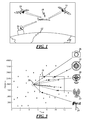
Figure 3 is a constellation map of data used by the method; and -
Figure 4 is a flow or logic chart of one embodiment of the method. - Unmanned vehicles, aircraft and watercraft require accurate navigational systems in order for them to operate as designed. If the navigational systems fail, or if the navigational systems are interfered with and compromised, the host vehicle quickly becomes a liability because it will either be a participant in an accident or it will be retrieved by someone other than the owner.
- A common example of an unmanned vehicle is an unmanned air vehicle (UAV), which is generally indicated at 10 in the Figures. The UAV 10 identifies its position with respect to the
earth 12 using an onboard navigational positioning system, such as the global positioning system GPS, graphically represented bysatellites 14. It should be appreciated by those skilled in the art that navigational positioning systems other than GPS may be used. And for purposes of simplicity, the navigational positioning system will be referred to hereinafter as the GPS. - The UAV 10 also receives commands from a
ground command base 16. As one skilled in the art will appreciate, theUAV 10 is vulnerable should theGPS 14 provide inaccurate data or no data and when another ground base similar to thecommand ground base 16 transmits signals to theUAV 10 to effectively change the mission or direction of theUAV 10. In such situations, the UAV 10 may be directed to land in a hostile territory or it may deploy its payload at a "spoofed" target other than the designated target for the mission of the UAV 10. - Referring to
Figure 2 , a redundant system passively checks the location of theUAV 10 and compares it to the data being received by theGPS 14. As is graphically represented inFigure 2 , theUAV 10 receives data in the form of electrical signals from anonboard compass 18, a three-axis gyroscope 20, and ground basedradio transmitters 22. Sources of electrical signals may also include the ground basedradio transmitters 22, which may provide a plurality of electromagnetic radiation signals from a plurality of spectral ranges. The spectral ranges are broadband and encompass multiple spectral ranges. - This list is not exhaustive and one skilled in the art may include other or additional inputs into the system utilizing the inventive method. In addition, ground based
radio transmitters 22 include, but are not limited to, television broadcast signals, radio broadcast signals, cell tower transmitters, and the like. - In
Figure 3 , thecompass 18, three-axis gyroscope 20, and ground basedradio transmitters 22 are graphically represented. In addition, amicrowave transmitting tower 24 is also shown to provide an input, although this may also be categorized with the generally ground basedradio transmitter 22. An additional input of visual data is illustrated inFigure 3 graphically by acamera 26. All of the data provided by each of theseinput devices target zone 28. Using the data located within thetarget zone 28, ananchor point 30 may be identified as the position of theUAV 10. In other words, by using the inventive method, the system may use combinatorial hashing using the inputs collected by theinput devices anchor point 30, which is the location of theUAV 10. This is done independently of the primary navigational system, theGPS 14. - In the instance of using optical data from the
camera 26, one embodiment may include the use of at least two cameras, presumably one at either end of a wing tip of theUAV 10. Using Euclidean geometry, one could calculate the distance between theUAV 10 and an object which is at the focal point of bothcameras 26. Use of thecameras 26 and anantennae system 32 onboard theUAV 10 is also used to identify the direction and location of theUAV 10 by collecting the combinatorial hash in a manner that allows the vector hash to be compared to positional data stored in an ephemeridlocation data base 34 on board theUAV 10. Through the use of combinatorial hashing, graphically represented bylogic circuit 36, a calculation may be made using the ephemerides to determine a particular location and direction in which theUAV 10 currently is operating. By use of combinatorial hashing 36, the ephemerid information will be automatically reviewed quickly and accurately to identify the location and direction of theUAV 10. In many or most instances, the combinatorial hashing will occur in parallel calculations due to the different types of ephemerides available for the calculation. By way of example only, data from acamera system 26 could be used to identify a general location of aUAV 10 independently of that information which is received by theantennae system 32, which receives broadcast information from ground basedradio transmitters 22 and microwave transmitting towers 24. Once all of the data is collected and the computation hashing is completed, a location and direction of theUAV 10 is available. - Referring to
Figure 4 , the inventive method is generally indicated at 100. The method starts at 102. Electromagnetic signals from ground basedradio transmitters 22 and microwave transmitting towers 24 are received at 104. Ideally, three of these electromagnetic signals are received. Ambient parameters are received and/or measured at 106. Ambient parameters are received and/or measured at 106. Ambient parameters include the data collected by thecameras 26. In addition, data received from thecompass 18, three-axis gyroscope 20 may be collected and used at this time period. Additionally, a very important piece of information is the time of day which would be collected independently of any navigational system and further refine the combinatorial hash function. - From the collected data and signals, a confirming location position is calculated at 108. The calculation is made by comparing the data collected with positional information stored in the
data base 34. As stated above, to ensure the accurate and quick calculation, the use of combinatorial hashing 36 is employed. - Once the confirming location position is calculated, the confirming location position is compared against the GPS location at 110. A differential factor is created at 112. The differential factor compares the location and direction of the confirming location position against the location and direction as indentified by the GPS location position. The
antennae system 32 transmits the differential vector to theground command base 16. If the differential vector is greater than a predetermined air value, a calculation done at 114 inFigure 4 , it is determined how to continue operation ofUAV 10. If the differential vector is not greater than the predetermined air value, theUAV 10 continues to be operated using the GPS location position signal it traditionally receives from theGPS 14. If, however, the differential vector is greater than a predetermined value, signals from theground command base 16 back to theUAV 10 prevent theUAV 10 from being controlled through the use of signals received by theGPS 14. The ground command base will instruct theUAV 10 to operate its directional functions based on the confirming location position at 120. The method then loops back and collects the information again and will operate theUAV 10 using the confirminglocation position 120 until the differential vector is less than a predetermined air value. - By use of the
method 100, theUAV 10 may be manually controlled independently of its primary navigational system, theGPS 14, which will allow theUAV 10 to operate without being interfered with by sources external the designed operational sources. - This description, rather than describing limitations of an invention, only illustrates an embodiment of the invention recited in the claims. The language of this description is therefore exclusively descriptive and is non-limiting. Obviously, it's possible to modify this invention from what the description teaches. Within the scope of the claims, one may practice the invention other than as described above.
Claims (15)
- A method for determining a physical location of a vehicle being guided with an onboard navigational positioning system capable of generating a location vector for a vehicle, the method comprising the steps of:receiving a plurality of electrical signals;calculating a confirming location position from the plurality of electrical signals;comparing the confirming location position to the location vector to create a position differential; andpreventing use of the location vector in directing movement of the vehicle until the position differential is below a predetermined error value.
- A method as set forth in claim 1 wherein the plurality of electrical signals includes a plurality of electromagnetic radiation signals.
- A method as set forth in claim 1 or claim 2, wherein the plurality of electrical signals further includes a plurality of ambient parameter measurements.
- A method as set forth in any one of claims 1 to 3, wherein each signal of the plurality of electromagnetic radiation signals is from a plurality of spectral ranges, and optionally wherein the spectral ranges are broadband and encompass multiple spectral ranges.
- A method as set forth in any one of the preceding claims, including the step of determining the location and direction of the vehicle by matching the confirming location vector to ephemeris data.
- A method as set forth in claim 3, or claim 4 or 5 when dependent from claim 3, wherein the step of comparing includes combinatorial hashing of the ambient parameter measurements.
- A method as set forth in any one of the preceding claims, wherein the step of comparing includes the use of ephemeris data.
- A method as set forth in any one of the preceding claims, including the use of an onboard digital compass, and/or including the use of an onboard three - axis gyroscope, and/or including the use of an onboard accelerometer, and/or including the use of an onboard ambient light sensor.
- A method as set forth in any one of the preceding claims including the step of repeating the step of comparing the confirming location position to the GPS location position throughout a time period the vehicle is moving.
- A method as set forth in any one of the preceding claims, further comprising the steps of:receiving a plurality of ambient parameter measurements;measuring the time at which each of the plurality of ambient parameter measurements are made;and wherein:the step of receiving a plurality of electrical signals comprises receiving a plurality of electromagnetic radiation signals,the step of calculating comprises calculating a confirming location position from the time measurement, the plurality of electromagnetic radiation signals and the plurality of ambient parameter measurements;the step of comparing comprises comparing the confirming location position to the location vector to create a differential vector; andthe step of preventing comprises preventing use of the onboard navigational positioning system in directing movement of the vehicle until the differential vector is below a predetermined error value.
- A method for determining a physical location of a vehicle being guided with an onboard navigational positioning system capable of generating a location vector for a vehicle, the method comprising the steps of:receiving a plurality of electromagnetic radiation signals;receiving a plurality of ambient parameter measurements;measuring the time at which each of the plurality of ambient parameter measurements are made;calculating a confirming location position from the time measurement, the plurality of electromagnetic radiation signals and the plurality of ambient parameter measurements;comparing the confirming location position to the location vector to create a differential vector; andpreventing use of the onboard navigational positioning system in directing movement of the vehicle until the differential vector is below a predetermined error value.
- A method as set forth in claim 10 or 11, wherein each signal of the plurality of electromagnetic radiation signals is from a plurality of spectral ranges, and/or wherein the spectral ranges are broadband and encompass multiple spectral ranges.
- A method as set forth in any one of claims 10 to 12, including the step of determining the location and direction of the vehicle by matching the confirming location vector to ephemeris data.
- A method as set forth in any one of claims 10 to 13, wherein the step of comparing includes combinatorial hashing of the ambient parameter measurements and/or wherein step of comparing includes the use of ephemeris data.
- A method as set forth in any one of claims 10 to 14, including the use of an onboard digital compass.
Applications Claiming Priority (1)
| Application Number | Priority Date | Filing Date | Title |
|---|---|---|---|
| US13/959,796 US9188979B2 (en) | 2013-08-06 | 2013-08-06 | Method and system for remotely controlling a vehicle |
Publications (2)
| Publication Number | Publication Date |
|---|---|
| EP2835708A2 true EP2835708A2 (en) | 2015-02-11 |
| EP2835708A3 EP2835708A3 (en) | 2015-04-29 |
Family
ID=51265629
Family Applications (1)
| Application Number | Title | Priority Date | Filing Date |
|---|---|---|---|
| EP20140180084 Ceased EP2835708A3 (en) | 2013-08-06 | 2014-08-06 | Method and system for remotely controlling a vehicle |
Country Status (4)
| Country | Link |
|---|---|
| US (1) | US9188979B2 (en) |
| EP (1) | EP2835708A3 (en) |
| JP (1) | JP6360744B2 (en) |
| AU (3) | AU2014208314A1 (en) |
Cited By (5)
| Publication number | Priority date | Publication date | Assignee | Title |
|---|---|---|---|---|
| CN105843245A (en) * | 2015-11-27 | 2016-08-10 | 深圳市星图智控科技有限公司 | Unmanned aerial vehicle control system and unmanned aerial vehicle control method |
| CN105912008A (en) * | 2016-06-13 | 2016-08-31 | 合肥赛为智能有限公司 | Electric power iron tower inspection unmanned plane flight control system and flight control method thereof |
| CN110015418A (en) * | 2015-03-31 | 2019-07-16 | 深圳市大疆创新科技有限公司 | For generating the Verification System and method of air traffic control |
| US11094202B2 (en) | 2015-03-31 | 2021-08-17 | SZ DJI Technology Co., Ltd. | Systems and methods for geo-fencing device communications |
| US11120456B2 (en) | 2015-03-31 | 2021-09-14 | SZ DJI Technology Co., Ltd. | Authentication systems and methods for generating flight regulations |
Families Citing this family (12)
| Publication number | Priority date | Publication date | Assignee | Title |
|---|---|---|---|---|
| DE102013217869A1 (en) * | 2013-09-06 | 2015-03-12 | Continental Teves Ag & Co. Ohg | Method and communication device for validating a data content of a wirelessly received communication signal and use of the communication device |
| US9862488B2 (en) | 2015-08-28 | 2018-01-09 | Mcafee, Llc | Location verification and secure no-fly logic for unmanned aerial vehicles |
| US10466700B1 (en) | 2015-09-25 | 2019-11-05 | Amazon Technologies, Inc. | Detecting of navigation data spoofing based on signal strength variance |
| US9847033B1 (en) | 2015-09-25 | 2017-12-19 | Amazon Technologies, Inc. | Communication of navigation data spoofing between unmanned vehicles |
| US9689686B1 (en) | 2015-09-25 | 2017-06-27 | Amazon Technologies, Inc. | Detecting of navigation data spoofing based on image data |
| US9725171B1 (en) * | 2015-09-25 | 2017-08-08 | Amazon Technologies, Inc. | Analyzing navigation data to detect navigation data spoofing |
| US9849978B1 (en) | 2015-09-25 | 2017-12-26 | Amazon Technologies, Inc. | Detecting of navigation data spoofing based on sensor data |
| CN108700667A (en) * | 2016-09-13 | 2018-10-23 | 雷古拉斯赛博有限公司 | The system and method for identifying the Global Navigation Satellite System spoofing attack to unmanned plane |
| JP6581629B2 (en) | 2017-08-17 | 2019-09-25 | 株式会社Subaru | Own machine position measuring device, own machine position measuring method, and own machine position measuring program |
| JP7178862B2 (en) * | 2018-10-17 | 2022-11-28 | 株式会社Subaru | AIRCRAFT POSITION MEASUREMENT SYSTEM, AIRCRAFT POSITION MEASUREMENT METHOD AND AIRCRAFT |
| CN113031018A (en) * | 2021-03-30 | 2021-06-25 | 北京航空航天大学东营研究院 | Beidou satellite navigation system performance testing device based on unmanned aerial vehicle |
| US12509243B2 (en) * | 2023-06-14 | 2025-12-30 | Pathfinder Systems, Inc. | Automated towed glider control system |
Family Cites Families (20)
| Publication number | Priority date | Publication date | Assignee | Title |
|---|---|---|---|---|
| US5983161A (en) * | 1993-08-11 | 1999-11-09 | Lemelson; Jerome H. | GPS vehicle collision avoidance warning and control system and method |
| US5757916A (en) * | 1995-10-06 | 1998-05-26 | International Series Research, Inc. | Method and apparatus for authenticating the location of remote users of networked computing systems |
| FR2776438B1 (en) | 1996-04-30 | 2000-05-05 | Dassault Electronique | MOBILE DETECTION SYSTEM USING DIGITAL TELEVISION BROADCASTING OF A NETWORK OF TERRESTRIAL TRANSMITTERS |
| US8203486B1 (en) | 1999-03-05 | 2012-06-19 | Omnipol A.S. | Transmitter independent techniques to extend the performance of passive coherent location |
| US7532895B2 (en) * | 2002-05-20 | 2009-05-12 | Air Defense, Inc. | Systems and methods for adaptive location tracking |
| JP2005080085A (en) * | 2003-09-02 | 2005-03-24 | Seiko Epson Corp | POSITION CHECKING DEVICE, POSITION CHECKING METHOD, POSITION CHECKING DEVICE CONTROL PROGRAM, AND COMPUTER-READABLE INFORMATION RECORDING MEDIUM CONTAINING THE POSITION CHECKING DEVICE CONTROL PROGRAM |
| US20060074558A1 (en) * | 2003-11-26 | 2006-04-06 | Williamson Walton R | Fault-tolerant system, apparatus and method |
| US7409290B2 (en) * | 2004-04-17 | 2008-08-05 | American Gnc Corporation | Positioning and navigation method and system thereof |
| KR101168100B1 (en) * | 2004-06-02 | 2012-07-24 | 록웰 콜린스 컨트롤 테크놀로지스, 인코포레이티드 | Systems and methods for estimating position, attitude and/or heading of a vehicle |
| JP2007245797A (en) * | 2006-03-14 | 2007-09-27 | Mitsubishi Electric Corp | Flight control device and flying object equipped with flight control device |
| US8296051B2 (en) * | 2006-05-18 | 2012-10-23 | The Boeing Company | Generalized high performance navigation system |
| US7554481B2 (en) * | 2006-05-18 | 2009-06-30 | The Boeing Company | Localized jamming of navigation signals |
| US8068984B2 (en) | 2006-10-17 | 2011-11-29 | Ut-Battelle, Llc | Triply redundant integrated navigation and asset visibility system |
| US8260567B1 (en) * | 2008-09-19 | 2012-09-04 | The United States Of America, As Represented By The Secretary Of The Navy | System and method for angles-only position and velocity determination using closed-form triangulation |
| DE102009016336A1 (en) | 2009-04-06 | 2010-10-07 | Continental Automotive Gmbh | Method for detecting global positioning system signals produced in unauthorized manner, involves receiving global positioning system signals for determining routing by global positioning system receiving unit |
| US20110109506A1 (en) | 2009-09-24 | 2011-05-12 | Coherent Navigation, Inc. | Simulating Phase-Coherent GNSS Signals |
| US8350758B1 (en) | 2009-10-01 | 2013-01-08 | Lighthouse Signal Systems LLC | Systems and methods for indoor geolocation based on yield of RF signals |
| JP5796896B2 (en) | 2011-03-10 | 2015-10-21 | 富士フイルム株式会社 | Tomographic image generating apparatus and method |
| FR2973518A1 (en) * | 2011-03-31 | 2012-10-05 | Thales Sa | POSITIONING SYSTEM WITH FRAUD DETECTION MECHANISM FOR CRITICAL APPLICATION |
| US9651666B2 (en) | 2011-04-19 | 2017-05-16 | The Boeing Company | Global positioning system signal reception with increased resistance to interference |
-
2013
- 2013-08-06 US US13/959,796 patent/US9188979B2/en active Active
-
2014
- 2014-08-05 AU AU2014208314A patent/AU2014208314A1/en not_active Abandoned
- 2014-08-06 EP EP20140180084 patent/EP2835708A3/en not_active Ceased
- 2014-08-06 JP JP2014160420A patent/JP6360744B2/en active Active
-
2019
- 2019-02-20 AU AU2019201191A patent/AU2019201191A1/en not_active Abandoned
-
2020
- 2020-09-28 AU AU2020244378A patent/AU2020244378A1/en not_active Abandoned
Non-Patent Citations (2)
| Title |
|---|
| "Assisted GPS", 28 July 2013 (2013-07-28), Retrieved from the Internet <URL:https://en.wikipedia.org/w/index.php?title=Assisted_GPS&oldid=566197710> [retrieved on 20180316] * |
| "GPS signals", 24 July 2013 (2013-07-24), Retrieved from the Internet <URL:https://en.wikipedia.org/w/index.php?title=GPS_signals&oldid=565675800> [retrieved on 20160511] * |
Cited By (8)
| Publication number | Priority date | Publication date | Assignee | Title |
|---|---|---|---|---|
| CN110015418A (en) * | 2015-03-31 | 2019-07-16 | 深圳市大疆创新科技有限公司 | For generating the Verification System and method of air traffic control |
| US11094202B2 (en) | 2015-03-31 | 2021-08-17 | SZ DJI Technology Co., Ltd. | Systems and methods for geo-fencing device communications |
| US11120456B2 (en) | 2015-03-31 | 2021-09-14 | SZ DJI Technology Co., Ltd. | Authentication systems and methods for generating flight regulations |
| US11367081B2 (en) | 2015-03-31 | 2022-06-21 | SZ DJI Technology Co., Ltd. | Authentication systems and methods for generating flight regulations |
| US11961093B2 (en) | 2015-03-31 | 2024-04-16 | SZ DJI Technology Co., Ltd. | Authentication systems and methods for generating flight regulations |
| US12067885B2 (en) | 2015-03-31 | 2024-08-20 | SZ DJI Technology Co., Ltd. | Systems and methods for geo-fencing device communications |
| CN105843245A (en) * | 2015-11-27 | 2016-08-10 | 深圳市星图智控科技有限公司 | Unmanned aerial vehicle control system and unmanned aerial vehicle control method |
| CN105912008A (en) * | 2016-06-13 | 2016-08-31 | 合肥赛为智能有限公司 | Electric power iron tower inspection unmanned plane flight control system and flight control method thereof |
Also Published As
| Publication number | Publication date |
|---|---|
| AU2014208314A1 (en) | 2015-02-26 |
| AU2020244378A1 (en) | 2020-10-29 |
| JP2015031699A (en) | 2015-02-16 |
| JP6360744B2 (en) | 2018-07-18 |
| US20150046017A1 (en) | 2015-02-12 |
| AU2019201191A1 (en) | 2019-03-14 |
| EP2835708A3 (en) | 2015-04-29 |
| US9188979B2 (en) | 2015-11-17 |
Similar Documents
| Publication | Publication Date | Title |
|---|---|---|
| US9188979B2 (en) | Method and system for remotely controlling a vehicle | |
| KR102463176B1 (en) | Device and method to estimate position | |
| US11150357B2 (en) | Multi-source distributed navigation system architecture | |
| US10175699B2 (en) | Method for automatically assisting with the landing of an aircraft | |
| US9728094B2 (en) | Redundant determination of positional data for an automatic landing system | |
| US10386202B2 (en) | Systems and methods for determining quality and integrity of source information to determine navigation information of an object | |
| US9483842B2 (en) | Navigation based on at least one sensor and a three dimensional map | |
| KR101798996B1 (en) | Method for calculating relative position of the vertical take-off and landing UAV and landing guide system for the UAV using the method | |
| CN107407937B (en) | Automatic assistance method for aircraft landing | |
| KR101908534B1 (en) | Apparatus and method for determining position and attitude of a vehicle | |
| EP2933603B1 (en) | Navigation based on at least one sensor and a 3d map | |
| EP3761062A1 (en) | Position determination of mobile objects | |
| US11043132B1 (en) | Systems and methods for determining quality and integrity of source information to determine navigation information of an object | |
| EP3120166B1 (en) | Precise positioning method | |
| US20190146093A1 (en) | Position measurement system for movable body | |
| KR101911353B1 (en) | Autonomic flight method when gnss signal loss and unmanned aerial vehicle for the same | |
| US20250172702A1 (en) | Multi-source distributed navigation system architecture | |
| US20180319511A1 (en) | Systems for and methods of providing indicators useful for piloting an aircraft | |
| KR101926237B1 (en) | Apparatus and method for measuring position | |
| US10234874B2 (en) | Autonomous vehicle control system | |
| KR20200064236A (en) | Structure inspection system and method using dron | |
| US20260085911A1 (en) | Method and system for target designation and autonomous launch control using a secure electronic network | |
| AU2018311656A1 (en) | In-flight azimuth determination |
Legal Events
| Date | Code | Title | Description |
|---|---|---|---|
| PUAI | Public reference made under article 153(3) epc to a published international application that has entered the european phase |
Free format text: ORIGINAL CODE: 0009012 |
|
| 17P | Request for examination filed |
Effective date: 20140806 |
|
| AK | Designated contracting states |
Kind code of ref document: A2 Designated state(s): AL AT BE BG CH CY CZ DE DK EE ES FI FR GB GR HR HU IE IS IT LI LT LU LV MC MK MT NL NO PL PT RO RS SE SI SK SM TR |
|
| AX | Request for extension of the european patent |
Extension state: BA ME |
|
| PUAL | Search report despatched |
Free format text: ORIGINAL CODE: 0009013 |
|
| AK | Designated contracting states |
Kind code of ref document: A3 Designated state(s): AL AT BE BG CH CY CZ DE DK EE ES FI FR GB GR HR HU IE IS IT LI LT LU LV MC MK MT NL NO PL PT RO RS SE SI SK SM TR |
|
| AX | Request for extension of the european patent |
Extension state: BA ME |
|
| RIC1 | Information provided on ipc code assigned before grant |
Ipc: G05D 1/00 20060101AFI20150326BHEP Ipc: G01S 19/21 20100101ALI20150326BHEP |
|
| R17P | Request for examination filed (corrected) |
Effective date: 20151029 |
|
| RBV | Designated contracting states (corrected) |
Designated state(s): AL AT BE BG CH CY CZ DE DK EE ES FI FR GB GR HR HU IE IS IT LI LT LU LV MC MK MT NL NO PL PT RO RS SE SI SK SM TR |
|
| 17Q | First examination report despatched |
Effective date: 20160602 |
|
| STAA | Information on the status of an ep patent application or granted ep patent |
Free format text: STATUS: THE APPLICATION HAS BEEN REFUSED |
|
| 18R | Application refused |
Effective date: 20181109 |