EP2835517B1 - An anti-ice system for preventing ice crystal accretion in gas turbine engines - Google Patents
An anti-ice system for preventing ice crystal accretion in gas turbine engines Download PDFInfo
- Publication number
- EP2835517B1 EP2835517B1 EP14179020.4A EP14179020A EP2835517B1 EP 2835517 B1 EP2835517 B1 EP 2835517B1 EP 14179020 A EP14179020 A EP 14179020A EP 2835517 B1 EP2835517 B1 EP 2835517B1
- Authority
- EP
- European Patent Office
- Prior art keywords
- engine
- ice
- gas turbine
- air
- components
- Prior art date
- Legal status (The legal status is an assumption and is not a legal conclusion. Google has not performed a legal analysis and makes no representation as to the accuracy of the status listed.)
- Active
Links
Images


Classifications
-
- F—MECHANICAL ENGINEERING; LIGHTING; HEATING; WEAPONS; BLASTING
- F02—COMBUSTION ENGINES; HOT-GAS OR COMBUSTION-PRODUCT ENGINE PLANTS
- F02C—GAS-TURBINE PLANTS; AIR INTAKES FOR JET-PROPULSION PLANTS; CONTROLLING FUEL SUPPLY IN AIR-BREATHING JET-PROPULSION PLANTS
- F02C7/00—Features, components parts, details or accessories, not provided for in, or of interest apart form groups F02C1/00 - F02C6/00; Air intakes for jet-propulsion plants
-
- F—MECHANICAL ENGINEERING; LIGHTING; HEATING; WEAPONS; BLASTING
- F02—COMBUSTION ENGINES; HOT-GAS OR COMBUSTION-PRODUCT ENGINE PLANTS
- F02C—GAS-TURBINE PLANTS; AIR INTAKES FOR JET-PROPULSION PLANTS; CONTROLLING FUEL SUPPLY IN AIR-BREATHING JET-PROPULSION PLANTS
- F02C7/00—Features, components parts, details or accessories, not provided for in, or of interest apart form groups F02C1/00 - F02C6/00; Air intakes for jet-propulsion plants
- F02C7/04—Air intakes for gas-turbine plants or jet-propulsion plants
- F02C7/047—Heating to prevent icing
-
- F—MECHANICAL ENGINEERING; LIGHTING; HEATING; WEAPONS; BLASTING
- F05—INDEXING SCHEMES RELATING TO ENGINES OR PUMPS IN VARIOUS SUBCLASSES OF CLASSES F01-F04
- F05D—INDEXING SCHEME FOR ASPECTS RELATING TO NON-POSITIVE-DISPLACEMENT MACHINES OR ENGINES, GAS-TURBINES OR JET-PROPULSION PLANTS
- F05D2260/00—Function
- F05D2260/20—Heat transfer, e.g. cooling
- F05D2260/231—Preventing heat transfer
-
- F—MECHANICAL ENGINEERING; LIGHTING; HEATING; WEAPONS; BLASTING
- F05—INDEXING SCHEMES RELATING TO ENGINES OR PUMPS IN VARIOUS SUBCLASSES OF CLASSES F01-F04
- F05D—INDEXING SCHEME FOR ASPECTS RELATING TO NON-POSITIVE-DISPLACEMENT MACHINES OR ENGINES, GAS-TURBINES OR JET-PROPULSION PLANTS
- F05D2270/00—Control
- F05D2270/30—Control parameters, e.g. input parameters
- F05D2270/311—Air humidity
-
- F—MECHANICAL ENGINEERING; LIGHTING; HEATING; WEAPONS; BLASTING
- F05—INDEXING SCHEMES RELATING TO ENGINES OR PUMPS IN VARIOUS SUBCLASSES OF CLASSES F01-F04
- F05D—INDEXING SCHEME FOR ASPECTS RELATING TO NON-POSITIVE-DISPLACEMENT MACHINES OR ENGINES, GAS-TURBINES OR JET-PROPULSION PLANTS
- F05D2270/00—Control
- F05D2270/30—Control parameters, e.g. input parameters
- F05D2270/312—Air pressure
-
- F—MECHANICAL ENGINEERING; LIGHTING; HEATING; WEAPONS; BLASTING
- F05—INDEXING SCHEMES RELATING TO ENGINES OR PUMPS IN VARIOUS SUBCLASSES OF CLASSES F01-F04
- F05D—INDEXING SCHEME FOR ASPECTS RELATING TO NON-POSITIVE-DISPLACEMENT MACHINES OR ENGINES, GAS-TURBINES OR JET-PROPULSION PLANTS
- F05D2270/00—Control
- F05D2270/30—Control parameters, e.g. input parameters
- F05D2270/313—Air temperature
-
- Y—GENERAL TAGGING OF NEW TECHNOLOGICAL DEVELOPMENTS; GENERAL TAGGING OF CROSS-SECTIONAL TECHNOLOGIES SPANNING OVER SEVERAL SECTIONS OF THE IPC; TECHNICAL SUBJECTS COVERED BY FORMER USPC CROSS-REFERENCE ART COLLECTIONS [XRACs] AND DIGESTS
- Y02—TECHNOLOGIES OR APPLICATIONS FOR MITIGATION OR ADAPTATION AGAINST CLIMATE CHANGE
- Y02T—CLIMATE CHANGE MITIGATION TECHNOLOGIES RELATED TO TRANSPORTATION
- Y02T50/00—Aeronautics or air transport
- Y02T50/60—Efficient propulsion technologies, e.g. for aircraft
Definitions
- the present invention generally relates to gas turbine engines, and more particularly relates to systems and methods for preventing ice crystal accretion in gas turbine engines.
- a gas turbine engine is used to power various types of vehicles and systems.
- a particular type of gas turbine engine that may be used to power aircraft is a turbofan gas turbine engine.
- a turbofan gas turbine engine typically includes five major sections: a fan section, a compressor section, a combustor section, a turbine section and an exhaust section.
- the fan section is positioned at the inlet section of the engine and includes a fan that induces air from the surrounding environment into the engine and accelerates a fraction of this air toward the compressor section.
- the compressor section raises the pressure of the air it receives from the fan section and directs a majority of the high pressure air into the combustor section.
- the high pressure air is mixed with fuel and combusted.
- the high-temperature combusted air is then directed into the turbine section where it expands through and rotates each turbine to drive various components within the engine or aircraft.
- the air is then exhausted through a propulsion nozzle disposed in the exhaust section.
- An aircraft turbofan gas turbine engine such as the one described above, may be exposed to numerous and varied environmental conditions.
- the engine may be exposed to various environmental conditions that may result in ice accretion at various locations on or within the engine.
- ice accretion can adversely affect engine performance and/or have various other deleterious effects on engine components.
- many aircraft include anti-ice systems to prevent ice accretion on various locations on or within the engine.
- FAA Federal Aviation Administration
- US4783026A discloses an anti-icing management system for a gas turbine engine according to which, at all times, only the required amount of heat is applied to inlet surfaces of the engine to prevent the formation of ice.
- the amount of flow of the heated air is adjusted by an electronic control responsive to the temperature of the anti-iced engine inlet surfaces directly in the path of incoming air.
- the electronic control may be effective when a separate ice detector determines the presence of ice and so informs the control.
- US2013008174A1 discloses a method of aircraft engine control involving detecting a difference between a temperature detected by a first temperature sensor and a temperature detected by a second temperature sensor. Anti-icing activity is initiated in response to the difference.
- the present invention provides an engine anti-ice system according to claim 1 of the appended claims.
- an engine anti-ice system includes one or more heat sources, one or more sensor data sources, and a controller.
- the one or more heat sources are configured to selectively heat one or more components on or within a gas turbine engine.
- the one or more sensor data sources are configured to supply data representative of one or more parameters related to ice crystal accretion.
- the controller is coupled to receive the data from the one or more sensors and is configured, in response to the data, to selectively at least inhibit at least selected ones of the one or more heat sources from supplying heat to at least selected ones of the one or more components on or within the gas turbine engine.
- an engine anti-ice system for an aircraft includes one or more heat sources, a temperature sensor, an altitude sensor, and a controller.
- the one or more heat sources are configured to selectively heat one or more components on or within a gas turbine engine.
- the temperature sensor is configured to sense ambient temperature outside of the aircraft and supply temperature data representative thereof.
- the altitude sensor is configured to sense aircraft altitude and supply altitude data representative thereof.
- the controller is coupled to receive the temperature data and the altitude data and is configured, in response to the temperature and altitude data, to selectively at least inhibit at least selected ones of the one or more heat sources from supplying heat to at least selected ones of the one or more components on or within the gas turbine engine.
- FIG. 1 a simplified cross section view of a turbofan gas turbine propulsion engine 100 is depicted.
- the depicted engine 100 includes an intake section 102, a compressor section 104, a combustion section 106, a turbine section 108, and an exhaust section 112.
- the intake section 102, compressor section 104, combustion section 106, turbine section 108, and exhaust section 112 are all mounted within a nacelle 114.
- the compressor section 104, combustion section 106, and turbine section 108 are all mounted within an engine case 116.
- the intake section 102 includes a fan 118, which draws air into the engine 100 and accelerates it.
- a spinner 120 is coupled to, and thus rotates with, the fan 118.
- the spinner 120 is configured to facilitate the correct flow of air into the fan 118.
- a fraction of the accelerated fan air that is exhausted from the fan 118 is directed through a fan air bypass duct 122 that is defined by an outer fan duct 124 that is spaced apart from and surrounds an inner fan duct 126. Most of the fan air that flows through the fan air bypass duct 122 is discharged from the bypass duct 122 to generate a forward thrust.
- the fraction of fan air that does not flow into the fan air bypass duct 122 is directed into the compressor section 104.
- the compressor section 104 can include one or more compressors.
- the engine 100 depicted in FIG. 1 includes two compressors - an intermediate pressure compressor 132 and a high pressure compressor 134. No matter the number of compressors it includes, the air that is directed into the compressor section 104 is pressurized to a relatively high pressure.
- the relatively high pressure air is then directed into the combustion section 106, which includes a combustor 136 to receive not only the relatively high pressure air, but atomized fuel.
- the relatively high pressure air and atomized fuel are mixed within the combustor 136 and the mixture is ignited to generate combusted air.
- the combusted air is then directed into the turbine section 108.
- the depicted turbine section 108 includes three turbines - a high pressure turbine 138, an intermediate pressure turbine 142, and a low pressure turbine 144 - though it should be appreciated that any number of turbines may be included.
- the combusted air directed into the turbine section 108 expands through each of turbines 138, 142, 144, causing each to rotate.
- the air is then exhausted through a propulsion nozzle 146 disposed in the exhaust section 112 to provide additional forward thrust.
- each drives equipment in the gas turbine engine 100 via concentrically disposed shafts or spools as best seen in FIG. 1 .
- the engine 100 may be exposed to various environmental conditions that may result in ice crystal accretion at various locations on or within the engine 100.
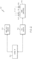
- an engine anti-ice system 150 an embodiment of which is depicted in more detail in FIG. 2 .
- the engine anti-ice system 150 may be variously configured and implemented, but in the depicted embodiment it includes one or more heat sources 152, one or more sensor data sources 154, and a controller 156.
- the one or more heat sources 152 and the one sensor data sources 154 are each depicted in FIG. 1 using a single functional block. It will be appreciated, however, that either or both of these functional blocks may represent single sources or multiple sources.
- the one or more heat sources 152 are configured to selectively heat one or more engine components 158 that are disposed on or within the engine 100.
- the one or more heat sources 152 may be one or more pneumatic, hydraulic, electric, or ultrasonic heat sources, just to name a few.
- the one or more heat sources 152 may be, but not limited to, relatively high-temperature bleed air from the engine 100 (or other source of relatively high-temperature air), and/or relatively high-temperature oil from, for example, a bearing sump, and/or electrical resistance heaters, and/or ultrasonic heaters.
- the one or more engine components 158 that the one or more heat sources 152 selectively heat may also vary.
- the engine components 158 include the spinner 120, one or more inlet guide vanes 121, and may additionally include one or more additional components disposed downstream of the inlet guide vanes 121. These one or more additional components may include guide vanes and/or other structure associated with the intermediate pressure compressor 132 and/or the high pressure compressor 134. It will be appreciated, however, that the engine components 158 may additionally or instead include various other components disposed on or within the engine 100 that are upstream of or within the compressor section 104.
- the one or more sensor data sources 154 are configured to supply data to the controller 156 that are representative of one or more parameters related to ice crystal accretion.
- the one or more parameters may vary and may include, for example, altitude and temperature and/or weather data and/or ice crystal presence.
- the one or more sensors 154 may include, for example, one or more altitude pressure sensors and one or more temperature sensors.
- the one or more parameters include weather data
- the one or more sensors 154 may include, for example, a weather radar system.
- the one or more parameters include ice crystal presence
- the one or more data sources 154 may include, for example, a Coherent Rayleigh Lidar system.
- the controller 156 is coupled to receive the data supplied thereby.
- the controller 156 is additionally configured, in response to the data, to selectively prevent (or at least inhibit) the one or more heat sources 152 from supplying heat to at least selected ones of the one or more engine components 158. More specifically, the controller 156 is configured, in response to the data, to determine if one or more criteria are met and, if so, to prevent (or inhibit) at least selected ones of the one or more heat sources 152 from supplying heat to at least selected ones of the one or more components 158. It will be appreciated that the one or more criteria may vary. For example, in one embodiment the criterion is that the aircraft is at or above a predetermined altitude and/or temperature.
- the criterion is that the weather conditions indicate a high likelihood that ice crystals are present in the air. In yet another embodiment, the criterion is that the presence of ice crystals has been detected.
- the controller 156 is additionally configured, upon determining that the one or more criteria are met, to supply appropriate commands to a controlled component 162 that is associated with a different one of the one or more engine components 158 to prevent (or inhibit) at least selected ones of the one or more heat sources 152 from supplying heat to at least selected ones of one or more engine components 158 on or within the engine 100.
- the type of commands that the controller 156 supplies may vary and may depend, for example, upon how the one or more controlled components 162 are implemented, which may in turn depend upon how the one or more heat sources 152 are implemented.
- relatively high-temperature lubricant is supplied to the spinner 120 and relatively high-temperature bleed air is supplied to the inlet guide vane(s) 121.
- the one or more controlled components 162 include an insulative shield and a valve.
- the insulative shield is disposed adjacent the spinner 120, and the valve is disposed on an air supply conduit between the inlet guide vane(s) 121 and the relatively high-temperature bleed air source.
- the controller 156 is configured, in response to determining that one or more criteria are met, to supply commands that control the positions of these controlled components 162.
- the controller 156 is configured to supply commands that will move the insulative shield between the spinner 121 and the relatively high-temperature lubricant source, and that will move the valve to a closed position to prevent bleed air from flowing to the inlet guide vane(s) 121.
- the controller 156 may also (or instead) be configured to de-energize one or more electrical heaters and/or ultrasonic heaters.
- the anti-ice system 150 is configured to selectively prevent (or at least inhibit) all of the heat sources 152 from supplying heat to all of the engine components 158 when one or more criteria are met. In other embodiments, the anti-ice system 150 is configured to selectively prevent (or at least inhibit) selected ones of the heat sources 152 from supplying heat to only selected ones of the engine components 158 when one or more criteria are met. For example, and with reference now to FIG.
- the anti-ice system 150 is configured such that all of the heat sources 152 supply heat to all of the engine components 158 whenever the aircraft is operating at altitudes and temperatures in temperature-altitude region I, and to selectively prevent (or at least inhibit) heating of all of the engine components 158 whenever the aircraft is operating at altitudes and temperatures in temperature-altitude regions II and III.
- the anti-ice system 150 is configured such that all of the heat sources 152 supply heat to all of the engine components 158 whenever the aircraft is operating at altitudes and temperatures in temperature-altitude region I, and to selectively prevent (or at least inhibit) heating of only selected ones of the engine components 158 whenever the aircraft is operating at altitudes and temperatures in temperature-altitude region II and at altitudes in temperature-altitude region III. It will be appreciated that the altitude-temperature regions depicted in FIG. 3 are merely exemplary, and that the anti-ice system 150 could be configured to selectively prevent (or at least inhibit) heating of selected ones of the engine components 158 in various other predefined altitude-temperature regions, if needed or desired.
- the anti-ice system 150 described herein actively controls the heating of one or more engine components 158 to prevent, or at least mitigate, ice crystal accretion by shutting down the source of liquid water when ice crystal conditions exist or are likely to exist. Specifically, by preventing (or at least inhibiting) at least selected ones of the one or more heat sources 152 from supplying heat to at least selected ones of the one or more engine components 158, the temperatures of the one or more engine components 158 will decrease, becoming relatively cold. Thus, these one or more engine components 158 will not melt ice crystals. Instead, the ice crystals will be deflected and sent back into the engine 100 with no liquid water. The ice crystals will then be unable to stick to the areas that accrete ice when the one or more heats sources 152 supply heat.
Landscapes
- Engineering & Computer Science (AREA)
- Chemical & Material Sciences (AREA)
- Combustion & Propulsion (AREA)
- Mechanical Engineering (AREA)
- General Engineering & Computer Science (AREA)
- Structures Of Non-Positive Displacement Pumps (AREA)
- Control Of Turbines (AREA)
Description
- The present invention generally relates to gas turbine engines, and more particularly relates to systems and methods for preventing ice crystal accretion in gas turbine engines.
- A gas turbine engine is used to power various types of vehicles and systems. A particular type of gas turbine engine that may be used to power aircraft is a turbofan gas turbine engine. A turbofan gas turbine engine typically includes five major sections: a fan section, a compressor section, a combustor section, a turbine section and an exhaust section. The fan section is positioned at the inlet section of the engine and includes a fan that induces air from the surrounding environment into the engine and accelerates a fraction of this air toward the compressor section. The compressor section raises the pressure of the air it receives from the fan section and directs a majority of the high pressure air into the combustor section. In the combustor section, the high pressure air is mixed with fuel and combusted. The high-temperature combusted air is then directed into the turbine section where it expands through and rotates each turbine to drive various components within the engine or aircraft. The air is then exhausted through a propulsion nozzle disposed in the exhaust section.
- An aircraft turbofan gas turbine engine, such as the one described above, may be exposed to numerous and varied environmental conditions. For example, the engine may be exposed to various environmental conditions that may result in ice accretion at various locations on or within the engine. Not surprisingly, such accretion can adversely affect engine performance and/or have various other deleterious effects on engine components. Thus, many aircraft include anti-ice systems to prevent ice accretion on various locations on or within the engine.
- Some governmental agencies, such as the Federal Aviation Administration (FAA), require many aircraft anti-ice systems be designed to prevent ice accretion, and more specifically supercooled droplet icing, on or within the engine up to a predefined certification altitudes and temperatures (e.g., 30,000 feet, -40 degrees Centigrade). Unfortunately, it has been discovered that these anti-ice systems are ineffective, and may even contribute to ice accretion through the addition of water droplets from melting ice crystals, at least during certain atmospheric conditions, at preventing ice crystal accretion at altitudes and temperatures above the predefined certification altitudes and temperatures.
- Hence, there is a need for an aircraft anti-ice system that will prevent ice crystal accretion on various locations one or within an engine even at altitudes and temperatures above the predefined certification altitudes and temperatures. The present invention addresses at least this need.
-
US4783026A discloses an anti-icing management system for a gas turbine engine according to which, at all times, only the required amount of heat is applied to inlet surfaces of the engine to prevent the formation of ice. The amount of flow of the heated air is adjusted by an electronic control responsive to the temperature of the anti-iced engine inlet surfaces directly in the path of incoming air. The electronic control may be effective when a separate ice detector determines the presence of ice and so informs the control. -
US2013008174A1 discloses a method of aircraft engine control involving detecting a difference between a temperature detected by a first temperature sensor and a temperature detected by a second temperature sensor. Anti-icing activity is initiated in response to the difference. - The present invention provides an engine anti-ice system according to claim 1 of the appended claims.
- In one embodiment, an engine anti-ice system includes one or more heat sources, one or more sensor data sources, and a controller. The one or more heat sources are configured to selectively heat one or more components on or within a gas turbine engine. The one or more sensor data sources are configured to supply data representative of one or more parameters related to ice crystal accretion. The controller is coupled to receive the data from the one or more sensors and is configured, in response to the data, to selectively at least inhibit at least selected ones of the one or more heat sources from supplying heat to at least selected ones of the one or more components on or within the gas turbine engine.
- In another embodiment, an engine anti-ice system for an aircraft includes one or more heat sources, a temperature sensor, an altitude sensor, and a controller. The one or more heat sources are configured to selectively heat one or more components on or within a gas turbine engine. The temperature sensor is configured to sense ambient temperature outside of the aircraft and supply temperature data representative thereof. The altitude sensor is configured to sense aircraft altitude and supply altitude data representative thereof. The controller is coupled to receive the temperature data and the altitude data and is configured, in response to the temperature and altitude data, to selectively at least inhibit at least selected ones of the one or more heat sources from supplying heat to at least selected ones of the one or more components on or within the gas turbine engine.
- Furthermore, other desirable features and characteristics of the engine anti-ice system and method will become apparent from the subsequent detailed description and the appended claims, taken in conjunction with the accompanying drawings and the preceding background.
- The present invention will hereinafter be described in conjunction with the following drawing figures, wherein like numerals denote like elements, and wherein:
-
FIG. 1 depicts a partial, simplified cross-sectional view of one embodiment of a turbofan gas turbine engine and associated anti-ice system; -
FIG. 2 depicts a functional block diagram of the anti-ice system depicted inFIG. 1 ; and -
FIG. 3 depicts a graph of altitude and temperature regions of differing anti-icing requirements. - The following detailed description is merely exemplary in nature and is not intended to limit the invention or the application and uses of the invention. As used herein, the word "exemplary" means "serving as an example, instance, or illustration." Thus, any embodiment described herein as "exemplary" is not necessarily to be construed as preferred or advantageous over other embodiments. All of the embodiments described herein are exemplary embodiments provided to enable persons skilled in the art to make or use the invention and not to limit the scope of the invention which is defined by the claims.
- Referring now to
FIG. 1 , a simplified cross section view of a turbofan gasturbine propulsion engine 100 is depicted. The depictedengine 100 includes anintake section 102, acompressor section 104, acombustion section 106, aturbine section 108, and anexhaust section 112. Theintake section 102,compressor section 104,combustion section 106,turbine section 108, andexhaust section 112 are all mounted within anacelle 114. Thecompressor section 104,combustion section 106, andturbine section 108 are all mounted within anengine case 116. - The
intake section 102 includes afan 118, which draws air into theengine 100 and accelerates it. Aspinner 120 is coupled to, and thus rotates with, thefan 118. Thespinner 120 is configured to facilitate the correct flow of air into thefan 118. A fraction of the accelerated fan air that is exhausted from thefan 118 is directed through a fanair bypass duct 122 that is defined by anouter fan duct 124 that is spaced apart from and surrounds aninner fan duct 126. Most of the fan air that flows through the fanair bypass duct 122 is discharged from thebypass duct 122 to generate a forward thrust. The fraction of fan air that does not flow into the fanair bypass duct 122 is directed into thecompressor section 104. - The
compressor section 104 can include one or more compressors. Theengine 100 depicted inFIG. 1 includes two compressors - anintermediate pressure compressor 132 and ahigh pressure compressor 134. No matter the number of compressors it includes, the air that is directed into thecompressor section 104 is pressurized to a relatively high pressure. The relatively high pressure air is then directed into thecombustion section 106, which includes acombustor 136 to receive not only the relatively high pressure air, but atomized fuel. The relatively high pressure air and atomized fuel are mixed within thecombustor 136 and the mixture is ignited to generate combusted air. The combusted air is then directed into theturbine section 108. - The depicted
turbine section 108 includes three turbines - ahigh pressure turbine 138, anintermediate pressure turbine 142, and a low pressure turbine 144 - though it should be appreciated that any number of turbines may be included. The combusted air directed into theturbine section 108 expands through each ofturbines propulsion nozzle 146 disposed in theexhaust section 112 to provide additional forward thrust. As theturbines gas turbine engine 100 via concentrically disposed shafts or spools as best seen inFIG. 1 . - The
engine 100 may be exposed to various environmental conditions that may result in ice crystal accretion at various locations on or within theengine 100. Thus, when theengine 100 is installed on an aircraft, it is interfaced with anengine anti-ice system 150, an embodiment of which is depicted in more detail inFIG. 2 . Theengine anti-ice system 150 may be variously configured and implemented, but in the depicted embodiment it includes one ormore heat sources 152, one or moresensor data sources 154, and acontroller 156. For convenience of illustration, the one ormore heat sources 152 and the onesensor data sources 154 are each depicted inFIG. 1 using a single functional block. It will be appreciated, however, that either or both of these functional blocks may represent single sources or multiple sources. - The one or
more heat sources 152 are configured to selectively heat one ormore engine components 158 that are disposed on or within theengine 100. The one ormore heat sources 152 may be one or more pneumatic, hydraulic, electric, or ultrasonic heat sources, just to name a few. For example, the one ormore heat sources 152 may be, but not limited to, relatively high-temperature bleed air from the engine 100 (or other source of relatively high-temperature air), and/or relatively high-temperature oil from, for example, a bearing sump, and/or electrical resistance heaters, and/or ultrasonic heaters. - The one or
more engine components 158 that the one ormore heat sources 152 selectively heat may also vary. In the depicted embodiment, theengine components 158 include thespinner 120, one or more inlet guidevanes 121, and may additionally include one or more additional components disposed downstream of the inlet guide vanes 121. These one or more additional components may include guide vanes and/or other structure associated with theintermediate pressure compressor 132 and/or thehigh pressure compressor 134. It will be appreciated, however, that theengine components 158 may additionally or instead include various other components disposed on or within theengine 100 that are upstream of or within thecompressor section 104. - The one or more
sensor data sources 154 are configured to supply data to thecontroller 156 that are representative of one or more parameters related to ice crystal accretion. The one or more parameters may vary and may include, for example, altitude and temperature and/or weather data and/or ice crystal presence. When the one or more parameters include altitude and temperature, the one ormore sensors 154 may include, for example, one or more altitude pressure sensors and one or more temperature sensors. When the one or more parameters include weather data, the one ormore sensors 154 may include, for example, a weather radar system. When the one or more parameters include ice crystal presence, the one ormore data sources 154 may include, for example, a Coherent Rayleigh Lidar system. - Regardless of how the one or
more data sources 154 are implemented, thecontroller 156 is coupled to receive the data supplied thereby. Thecontroller 156 is additionally configured, in response to the data, to selectively prevent (or at least inhibit) the one ormore heat sources 152 from supplying heat to at least selected ones of the one ormore engine components 158. More specifically, thecontroller 156 is configured, in response to the data, to determine if one or more criteria are met and, if so, to prevent (or inhibit) at least selected ones of the one ormore heat sources 152 from supplying heat to at least selected ones of the one ormore components 158. It will be appreciated that the one or more criteria may vary. For example, in one embodiment the criterion is that the aircraft is at or above a predetermined altitude and/or temperature. In another embodiment, the criterion is that the weather conditions indicate a high likelihood that ice crystals are present in the air. In yet another embodiment, the criterion is that the presence of ice crystals has been detected. Before proceeding further, the reason for this functionality will now be described. - It was previously noted that most
aircraft anti-ice systems 150 are designed to prevent supercooled droplet icing up to a predefined certification altitude and at a predefined certification temperature (e.g., 30,000 feet, -40 degrees Centigrade). Above these certification altitudes and temperatures supercooled droplets are typically not present. However, ice crystals may be present, and some turbofangas turbine engines 100 are susceptible to ice crystal accretion. Ice crystal accretion in a turbofangas turbine engine 100, and most typically in thecompressor section 104 of anengine 100, can initiate when ice crystals hit aheated component 158. The ice crystals melt and send water droplets back into thecompressor section 104. These water droplets may then combine with unmelted ice crystals and stick to compressor vanes. This can potentially result in several undesirable effects. For example, this can potentially cause flow blockage, ice shedding, surge, stall, or combustor flame out. - Returning now to the description, the
controller 156 is additionally configured, upon determining that the one or more criteria are met, to supply appropriate commands to a controlledcomponent 162 that is associated with a different one of the one ormore engine components 158 to prevent (or inhibit) at least selected ones of the one ormore heat sources 152 from supplying heat to at least selected ones of one ormore engine components 158 on or within theengine 100. The type of commands that thecontroller 156 supplies may vary and may depend, for example, upon how the one or more controlledcomponents 162 are implemented, which may in turn depend upon how the one ormore heat sources 152 are implemented. For example, in one particular embodiment, relatively high-temperature lubricant is supplied to thespinner 120 and relatively high-temperature bleed air is supplied to the inlet guide vane(s) 121. In this particular embodiment, the one or more controlledcomponents 162 include an insulative shield and a valve. The insulative shield is disposed adjacent thespinner 120, and the valve is disposed on an air supply conduit between the inlet guide vane(s) 121 and the relatively high-temperature bleed air source. Thecontroller 156 is configured, in response to determining that one or more criteria are met, to supply commands that control the positions of these controlledcomponents 162. Specifically, thecontroller 156 is configured to supply commands that will move the insulative shield between thespinner 121 and the relatively high-temperature lubricant source, and that will move the valve to a closed position to prevent bleed air from flowing to the inlet guide vane(s) 121. In other embodiments, thecontroller 156 may also (or instead) be configured to de-energize one or more electrical heaters and/or ultrasonic heaters. - It should be noted that with some embodiments, the
anti-ice system 150 is configured to selectively prevent (or at least inhibit) all of theheat sources 152 from supplying heat to all of theengine components 158 when one or more criteria are met. In other embodiments, theanti-ice system 150 is configured to selectively prevent (or at least inhibit) selected ones of theheat sources 152 from supplying heat to only selected ones of theengine components 158 when one or more criteria are met. For example, and with reference now toFIG. 3 , in some embodiments theanti-ice system 150 is configured such that all of theheat sources 152 supply heat to all of theengine components 158 whenever the aircraft is operating at altitudes and temperatures in temperature-altitude region I, and to selectively prevent (or at least inhibit) heating of all of theengine components 158 whenever the aircraft is operating at altitudes and temperatures in temperature-altitude regions II and III. In other embodiments, however, theanti-ice system 150 is configured such that all of theheat sources 152 supply heat to all of theengine components 158 whenever the aircraft is operating at altitudes and temperatures in temperature-altitude region I, and to selectively prevent (or at least inhibit) heating of only selected ones of theengine components 158 whenever the aircraft is operating at altitudes and temperatures in temperature-altitude region II and at altitudes in temperature-altitude region III. It will be appreciated that the altitude-temperature regions depicted inFIG. 3 are merely exemplary, and that theanti-ice system 150 could be configured to selectively prevent (or at least inhibit) heating of selected ones of theengine components 158 in various other predefined altitude-temperature regions, if needed or desired. - The
anti-ice system 150 described herein actively controls the heating of one ormore engine components 158 to prevent, or at least mitigate, ice crystal accretion by shutting down the source of liquid water when ice crystal conditions exist or are likely to exist. Specifically, by preventing (or at least inhibiting) at least selected ones of the one ormore heat sources 152 from supplying heat to at least selected ones of the one ormore engine components 158, the temperatures of the one ormore engine components 158 will decrease, becoming relatively cold. Thus, these one ormore engine components 158 will not melt ice crystals. Instead, the ice crystals will be deflected and sent back into theengine 100 with no liquid water. The ice crystals will then be unable to stick to the areas that accrete ice when the one ormore heats sources 152 supply heat. - In this document, relational terms such as first and second, and the like may be used solely to distinguish one entity or action from another entity or action without necessarily requiring or implying any actual such relationship or order between such entities or actions. Numerical ordinals such as "first," "second," "third," etc. simply denote different singles of a plurality and do not imply any order or sequence unless specifically defined by the claim language. The sequence of the text in any of the claims does not imply that process steps must be performed in a temporal or logical order according to such sequence unless it is specifically defined by the language of the claim. The process steps may be interchanged in any order without departing from the scope of the invention as long as such an interchange does not contradict the claim language and is not logically nonsensical.
- While at least one exemplary embodiment has been presented in the foregoing detailed description of the invention, it should be appreciated that a vast number of variations exist. It should also be appreciated that the exemplary embodiment or exemplary embodiments are only examples, and are not intended to limit the scope, applicability, or configuration of the invention in any way. Rather, the foregoing detailed description will provide those skilled in the art with a convenient road map for implementing an exemplary embodiment of the invention. It being understood that various changes may be made in the function and arrangement of elements described in an exemplary embodiment without departing from the scope of the invention as set forth in the appended claims.
Claims (7)
- An engine anti-ice system (150), comprising:one or more heat sources (152) configured to selectively heat one or more components (158) on or within a gas turbine engine (100);one or more sensor data sources (154) configured to supply data representative of one or more parameters related to ice crystal accretion; anda controller (156) coupled to receive the data from the one or more sensors (154) ;characterised in that the controller is
configured, in response to the data, to (i) determine if one or more criteria are met, and (ii) when the one or more criteria are met, selectively at least inhibit at least selected ones of the one or more heat sources from supplying heat to at least selected ones of the one or more components on or within the gas turbine engine,
wherein the one or more criteria comprise one or more of aircraft altitude being at or above a predetermined altitude, a likelihood of ice crystal presence in the air, and ice crystal presence in the air has been detected. - The system of claim 1, wherein the one or more criteria further comprises ambient temperature outside the aircraft is less than or equal to a predetermined temperature.
- The system of claim 1, wherein the one or more heat sources (152) comprise engine bleed air.
- The system of claim 1, wherein the one or more heat sources (152) comprise one or more of a lubricant, one or more electrical heaters, and one or more ultrasonic heaters.
- The system of claim 1, wherein the one or more components (158) comprise one or more of a spinner (120), or one or more guide vanes.
- The system of claim 1, wherein the one or more sensor data sources (154) comprise:one or more altitude sensors; andone or more temperature sensors.
- The system of claim 1, wherein the one or more sensor data sources (154) comprise one or more of a weather radar system or a Coherent Rayleigh Lidar System.
Applications Claiming Priority (2)
| Application Number | Priority Date | Filing Date | Title |
|---|---|---|---|
| US201361864309P | 2013-08-09 | 2013-08-09 | |
| US14/014,560 US9683489B2 (en) | 2013-08-09 | 2013-08-30 | System and method for preventing ice crystal accretion in gas turbine engines |
Publications (2)
| Publication Number | Publication Date |
|---|---|
| EP2835517A1 EP2835517A1 (en) | 2015-02-11 |
| EP2835517B1 true EP2835517B1 (en) | 2018-06-20 |
Family
ID=51265504
Family Applications (1)
| Application Number | Title | Priority Date | Filing Date |
|---|---|---|---|
| EP14179020.4A Active EP2835517B1 (en) | 2013-08-09 | 2014-07-29 | An anti-ice system for preventing ice crystal accretion in gas turbine engines |
Country Status (2)
| Country | Link |
|---|---|
| US (1) | US9683489B2 (en) |
| EP (1) | EP2835517B1 (en) |
Families Citing this family (7)
| Publication number | Priority date | Publication date | Assignee | Title |
|---|---|---|---|---|
| WO2016145325A1 (en) * | 2015-03-12 | 2016-09-15 | Sikorsky Aircraft Corporation | Conditional engine igniters |
| US10184405B1 (en) * | 2016-04-15 | 2019-01-22 | The United States Of America As Represented By The Administrator Of National Aeronautics And Space Administration | Aircraft engine icing event avoidance and mitigation through real-time simulation and controls |
| CN105836139A (en) * | 2016-05-18 | 2016-08-10 | 中国航空工业集团公司西安飞机设计研究所 | Automatic airbag deicing system |
| DE102016111902B4 (en) * | 2016-06-29 | 2024-08-01 | Deutsches Zentrum für Luft- und Raumfahrt e.V. | Procedure and assistance system for detecting flight performance degradation |
| US10392117B2 (en) * | 2016-09-23 | 2019-08-27 | General Electric Company | Icing condition detection using instantaneous humidity sensing |
| US11428119B2 (en) * | 2019-12-18 | 2022-08-30 | Pratt & Whitney Canada Corp. | Method and system to promote ice shedding from rotor blades of an aircraft engine |
| US12577910B1 (en) * | 2025-03-31 | 2026-03-17 | Rtx Corporation | Gas turbine engine with compartment anti-icing system |
Family Cites Families (21)
| Publication number | Priority date | Publication date | Assignee | Title |
|---|---|---|---|---|
| GB621464A (en) | 1943-08-11 | 1949-04-11 | Bendix Aviat Corp | Control system for de-icer equipment |
| US3834157A (en) | 1973-02-05 | 1974-09-10 | Avco Corp | Spinner de-icing for gas turbine engines |
| GB1547985A (en) | 1976-06-04 | 1979-07-04 | Lucas Industries Ltd | Apparatus for indicating rate of ice accretion |
| US4783026A (en) | 1987-05-22 | 1988-11-08 | Avco Corporation | Anti-icing management system |
| US4831819A (en) | 1987-07-02 | 1989-05-23 | Avco Corporation | Anti-icing valve |
| GB2241536A (en) | 1988-03-23 | 1991-09-04 | Rolls Royce Plc | Intakes of aerospace propulsors |
| GB2241537B (en) * | 1988-03-23 | 1992-08-12 | Rolls Royce Plc | The prevention of icing in the intakes of aerospace propulsors. |
| US5216477A (en) * | 1991-05-20 | 1993-06-01 | Korb Charles L | Edge technique for measurement of laser frequency shifts including the doppler shift |
| US5488375A (en) * | 1994-09-28 | 1996-01-30 | Alliedsignal Inc. | Airborne weather radar system with icing detection capabiliy |
| US6725645B1 (en) | 2002-10-03 | 2004-04-27 | General Electric Company | Turbofan engine internal anti-ice device |
| US7175136B2 (en) | 2003-04-16 | 2007-02-13 | The Boeing Company | Method and apparatus for detecting conditions conducive to ice formation |
| DE60329634D1 (en) * | 2003-08-20 | 2009-11-19 | Boeing Co | METHOD AND SYSTEMS FOR DETERMINING TEMPERING CONDITIONS |
| IL187246A0 (en) | 2007-11-08 | 2009-05-04 | Rafael Advanced Defense Sys | Method of preventing the ice formation on surfaces |
| US8265805B2 (en) | 2007-11-11 | 2012-09-11 | The Boeing Company | Method and apparatus for detecting icing conditions for an aircraft |
| US9656757B2 (en) | 2008-09-16 | 2017-05-23 | Hamilton Sundstrand Corporation | Propeller deicing system |
| GB0917319D0 (en) * | 2009-10-05 | 2009-11-18 | Rolls Royce Plc | An apparatus and method of operating a gas turbine engine |
| JP2012145531A (en) * | 2011-01-14 | 2012-08-02 | Japan Aerospace Exploration Agency | Atmosphere suspended substance detection lidar for aircraft |
| US9133773B2 (en) | 2011-07-08 | 2015-09-15 | United Technologies Corporation | Method and controller for detecting ice |
| GB201112577D0 (en) * | 2011-07-22 | 2011-08-31 | Rolls Royce Plc | Method of inhibiting ice accretion within a turbine engine and control system therefor |
| US9327839B2 (en) | 2011-08-05 | 2016-05-03 | General Atomics | Method and apparatus for inhibiting formation of and/or removing ice from aircraft components |
| US8452516B1 (en) | 2012-01-31 | 2013-05-28 | United Technologies Corporation | Variable vane scheduling based on flight conditions for inclement weather |
-
2013
- 2013-08-30 US US14/014,560 patent/US9683489B2/en active Active
-
2014
- 2014-07-29 EP EP14179020.4A patent/EP2835517B1/en active Active
Non-Patent Citations (1)
| Title |
|---|
| None * |
Also Published As
| Publication number | Publication date |
|---|---|
| US20150040577A1 (en) | 2015-02-12 |
| EP2835517A1 (en) | 2015-02-11 |
| US9683489B2 (en) | 2017-06-20 |
Similar Documents
| Publication | Publication Date | Title |
|---|---|---|
| US9683489B2 (en) | System and method for preventing ice crystal accretion in gas turbine engines | |
| US9260974B2 (en) | System and method for active clearance control | |
| EP2543597B1 (en) | Method and controller for detecting ice | |
| US20120240594A1 (en) | Method and apparatus for protecting aircraft engines against icing | |
| CN115108030A (en) | Hydrogen fuel leakage detection system | |
| US20110004388A1 (en) | Turbofan temperature control with variable area nozzle | |
| US20140033731A1 (en) | Method for fuel temperature control of a gas turbine | |
| US6725645B1 (en) | Turbofan engine internal anti-ice device | |
| US11780597B2 (en) | Aircraft propulsion | |
| US20230294833A1 (en) | Ice protection systems for aircraft | |
| US20160311546A1 (en) | Method, system, and apparatus for reducing a turbine clearance | |
| EP3828078B1 (en) | Gas turbine engine, nacelle thereof, and associated method of operating a gas turbine engine | |
| EP3693557B1 (en) | Duct rupture detection system | |
| Veres et al. | Modeling of commercial turbofan engine with ice crystal ingestion; follow-on | |
| US20090241509A1 (en) | Turbine engine inlet strut deicing | |
| EP3106649B1 (en) | Aircraft gas turbine propulsion engine control without aircraft total air temperature sensors | |
| US10961907B2 (en) | Aircraft incorporating a low-temperature bleed system | |
| Bin et al. | Icing certification of civil aircraft engines | |
| Mahmood et al. | Thrust reverser for a mixed exhaust high bypass ratio turbofan engine and its effect on aircraft and engine performance | |
| Markowski et al. | Evaluation of turbine microjet engine operating parameters in conditions conducive to inlet freezing | |
| GB2552048A (en) | Method, system, and apparatus for reducing a turbine clearance | |
| EP4407168B1 (en) | Icing condition identification for gas turbine engine | |
| RU2814576C1 (en) | Device for combating crystal icing of turbofan engines (tdce) | |
| US11970971B2 (en) | Heat transfer system for gas turbine engine | |
| Xiaogang | Flight Test Investigation to the Start Performance of Military Aircraft APU Considered with Airworthiness |
Legal Events
| Date | Code | Title | Description |
|---|---|---|---|
| PUAI | Public reference made under article 153(3) epc to a published international application that has entered the european phase |
Free format text: ORIGINAL CODE: 0009012 |
|
| 17P | Request for examination filed |
Effective date: 20140729 |
|
| AK | Designated contracting states |
Kind code of ref document: A1 Designated state(s): AL AT BE BG CH CY CZ DE DK EE ES FI FR GB GR HR HU IE IS IT LI LT LU LV MC MK MT NL NO PL PT RO RS SE SI SK SM TR |
|
| AX | Request for extension of the european patent |
Extension state: BA ME |
|
| RAP1 | Party data changed (applicant data changed or rights of an application transferred) |
Owner name: HONEYWELL INTERNATIONAL INC. |
|
| GRAP | Despatch of communication of intention to grant a patent |
Free format text: ORIGINAL CODE: EPIDOSNIGR1 |
|
| INTG | Intention to grant announced |
Effective date: 20180102 |
|
| GRAJ | Information related to disapproval of communication of intention to grant by the applicant or resumption of examination proceedings by the epo deleted |
Free format text: ORIGINAL CODE: EPIDOSDIGR1 |
|
| GRAS | Grant fee paid |
Free format text: ORIGINAL CODE: EPIDOSNIGR3 |
|
| GRAP | Despatch of communication of intention to grant a patent |
Free format text: ORIGINAL CODE: EPIDOSNIGR1 |
|
| INTC | Intention to grant announced (deleted) | ||
| GRAA | (expected) grant |
Free format text: ORIGINAL CODE: 0009210 |
|
| INTG | Intention to grant announced |
Effective date: 20180430 |
|
| AK | Designated contracting states |
Kind code of ref document: B1 Designated state(s): AL AT BE BG CH CY CZ DE DK EE ES FI FR GB GR HR HU IE IS IT LI LT LU LV MC MK MT NL NO PL PT RO RS SE SI SK SM TR |
|
| REG | Reference to a national code |
Ref country code: GB Ref legal event code: FG4D |
|
| REG | Reference to a national code |
Ref country code: IE Ref legal event code: FG4D |
|
| REG | Reference to a national code |
Ref country code: AT Ref legal event code: REF Ref document number: 1010759 Country of ref document: AT Kind code of ref document: T Effective date: 20180715 |
|
| REG | Reference to a national code |
Ref country code: DE Ref legal event code: R096 Ref document number: 602014027231 Country of ref document: DE |
|
| REG | Reference to a national code |
Ref country code: NL Ref legal event code: MP Effective date: 20180620 |
|
| PG25 | Lapsed in a contracting state [announced via postgrant information from national office to epo] |
Ref country code: NO Free format text: LAPSE BECAUSE OF FAILURE TO SUBMIT A TRANSLATION OF THE DESCRIPTION OR TO PAY THE FEE WITHIN THE PRESCRIBED TIME-LIMIT Effective date: 20180920 Ref country code: SE Free format text: LAPSE BECAUSE OF FAILURE TO SUBMIT A TRANSLATION OF THE DESCRIPTION OR TO PAY THE FEE WITHIN THE PRESCRIBED TIME-LIMIT Effective date: 20180620 Ref country code: LT Free format text: LAPSE BECAUSE OF FAILURE TO SUBMIT A TRANSLATION OF THE DESCRIPTION OR TO PAY THE FEE WITHIN THE PRESCRIBED TIME-LIMIT Effective date: 20180620 Ref country code: FI Free format text: LAPSE BECAUSE OF FAILURE TO SUBMIT A TRANSLATION OF THE DESCRIPTION OR TO PAY THE FEE WITHIN THE PRESCRIBED TIME-LIMIT Effective date: 20180620 Ref country code: BG Free format text: LAPSE BECAUSE OF FAILURE TO SUBMIT A TRANSLATION OF THE DESCRIPTION OR TO PAY THE FEE WITHIN THE PRESCRIBED TIME-LIMIT Effective date: 20180920 |
|
| REG | Reference to a national code |
Ref country code: LT Ref legal event code: MG4D |
|
| PG25 | Lapsed in a contracting state [announced via postgrant information from national office to epo] |
Ref country code: HR Free format text: LAPSE BECAUSE OF FAILURE TO SUBMIT A TRANSLATION OF THE DESCRIPTION OR TO PAY THE FEE WITHIN THE PRESCRIBED TIME-LIMIT Effective date: 20180620 Ref country code: RS Free format text: LAPSE BECAUSE OF FAILURE TO SUBMIT A TRANSLATION OF THE DESCRIPTION OR TO PAY THE FEE WITHIN THE PRESCRIBED TIME-LIMIT Effective date: 20180620 Ref country code: LV Free format text: LAPSE BECAUSE OF FAILURE TO SUBMIT A TRANSLATION OF THE DESCRIPTION OR TO PAY THE FEE WITHIN THE PRESCRIBED TIME-LIMIT Effective date: 20180620 Ref country code: GR Free format text: LAPSE BECAUSE OF FAILURE TO SUBMIT A TRANSLATION OF THE DESCRIPTION OR TO PAY THE FEE WITHIN THE PRESCRIBED TIME-LIMIT Effective date: 20180921 |
|
| REG | Reference to a national code |
Ref country code: AT Ref legal event code: MK05 Ref document number: 1010759 Country of ref document: AT Kind code of ref document: T Effective date: 20180620 |
|
| PG25 | Lapsed in a contracting state [announced via postgrant information from national office to epo] |
Ref country code: NL Free format text: LAPSE BECAUSE OF FAILURE TO SUBMIT A TRANSLATION OF THE DESCRIPTION OR TO PAY THE FEE WITHIN THE PRESCRIBED TIME-LIMIT Effective date: 20180620 |
|
| PG25 | Lapsed in a contracting state [announced via postgrant information from national office to epo] |
Ref country code: SK Free format text: LAPSE BECAUSE OF FAILURE TO SUBMIT A TRANSLATION OF THE DESCRIPTION OR TO PAY THE FEE WITHIN THE PRESCRIBED TIME-LIMIT Effective date: 20180620 Ref country code: EE Free format text: LAPSE BECAUSE OF FAILURE TO SUBMIT A TRANSLATION OF THE DESCRIPTION OR TO PAY THE FEE WITHIN THE PRESCRIBED TIME-LIMIT Effective date: 20180620 Ref country code: IS Free format text: LAPSE BECAUSE OF FAILURE TO SUBMIT A TRANSLATION OF THE DESCRIPTION OR TO PAY THE FEE WITHIN THE PRESCRIBED TIME-LIMIT Effective date: 20181020 Ref country code: AT Free format text: LAPSE BECAUSE OF FAILURE TO SUBMIT A TRANSLATION OF THE DESCRIPTION OR TO PAY THE FEE WITHIN THE PRESCRIBED TIME-LIMIT Effective date: 20180620 Ref country code: CZ Free format text: LAPSE BECAUSE OF FAILURE TO SUBMIT A TRANSLATION OF THE DESCRIPTION OR TO PAY THE FEE WITHIN THE PRESCRIBED TIME-LIMIT Effective date: 20180620 Ref country code: PL Free format text: LAPSE BECAUSE OF FAILURE TO SUBMIT A TRANSLATION OF THE DESCRIPTION OR TO PAY THE FEE WITHIN THE PRESCRIBED TIME-LIMIT Effective date: 20180620 Ref country code: RO Free format text: LAPSE BECAUSE OF FAILURE TO SUBMIT A TRANSLATION OF THE DESCRIPTION OR TO PAY THE FEE WITHIN THE PRESCRIBED TIME-LIMIT Effective date: 20180620 |
|
| PG25 | Lapsed in a contracting state [announced via postgrant information from national office to epo] |
Ref country code: SM Free format text: LAPSE BECAUSE OF FAILURE TO SUBMIT A TRANSLATION OF THE DESCRIPTION OR TO PAY THE FEE WITHIN THE PRESCRIBED TIME-LIMIT Effective date: 20180620 Ref country code: ES Free format text: LAPSE BECAUSE OF FAILURE TO SUBMIT A TRANSLATION OF THE DESCRIPTION OR TO PAY THE FEE WITHIN THE PRESCRIBED TIME-LIMIT Effective date: 20180620 Ref country code: IT Free format text: LAPSE BECAUSE OF FAILURE TO SUBMIT A TRANSLATION OF THE DESCRIPTION OR TO PAY THE FEE WITHIN THE PRESCRIBED TIME-LIMIT Effective date: 20180620 |
|
| REG | Reference to a national code |
Ref country code: CH Ref legal event code: PL |
|
| REG | Reference to a national code |
Ref country code: DE Ref legal event code: R097 Ref document number: 602014027231 Country of ref document: DE |
|
| PG25 | Lapsed in a contracting state [announced via postgrant information from national office to epo] |
Ref country code: LU Free format text: LAPSE BECAUSE OF NON-PAYMENT OF DUE FEES Effective date: 20180729 Ref country code: MC Free format text: LAPSE BECAUSE OF FAILURE TO SUBMIT A TRANSLATION OF THE DESCRIPTION OR TO PAY THE FEE WITHIN THE PRESCRIBED TIME-LIMIT Effective date: 20180620 |
|
| REG | Reference to a national code |
Ref country code: BE Ref legal event code: MM Effective date: 20180731 |
|
| PLBE | No opposition filed within time limit |
Free format text: ORIGINAL CODE: 0009261 |
|
| STAA | Information on the status of an ep patent application or granted ep patent |
Free format text: STATUS: NO OPPOSITION FILED WITHIN TIME LIMIT |
|
| PG25 | Lapsed in a contracting state [announced via postgrant information from national office to epo] |
Ref country code: CH Free format text: LAPSE BECAUSE OF NON-PAYMENT OF DUE FEES Effective date: 20180731 Ref country code: LI Free format text: LAPSE BECAUSE OF NON-PAYMENT OF DUE FEES Effective date: 20180731 |
|
| REG | Reference to a national code |
Ref country code: IE Ref legal event code: MM4A |
|
| GBPC | Gb: european patent ceased through non-payment of renewal fee |
Effective date: 20180920 |
|
| 26N | No opposition filed |
Effective date: 20190321 |
|
| PG25 | Lapsed in a contracting state [announced via postgrant information from national office to epo] |
Ref country code: DK Free format text: LAPSE BECAUSE OF FAILURE TO SUBMIT A TRANSLATION OF THE DESCRIPTION OR TO PAY THE FEE WITHIN THE PRESCRIBED TIME-LIMIT Effective date: 20180620 Ref country code: BE Free format text: LAPSE BECAUSE OF NON-PAYMENT OF DUE FEES Effective date: 20180731 |
|
| PG25 | Lapsed in a contracting state [announced via postgrant information from national office to epo] |
Ref country code: IE Free format text: LAPSE BECAUSE OF NON-PAYMENT OF DUE FEES Effective date: 20180729 |
|
| PG25 | Lapsed in a contracting state [announced via postgrant information from national office to epo] |
Ref country code: SI Free format text: LAPSE BECAUSE OF FAILURE TO SUBMIT A TRANSLATION OF THE DESCRIPTION OR TO PAY THE FEE WITHIN THE PRESCRIBED TIME-LIMIT Effective date: 20180620 Ref country code: FR Free format text: LAPSE BECAUSE OF NON-PAYMENT OF DUE FEES Effective date: 20180820 |
|
| PG25 | Lapsed in a contracting state [announced via postgrant information from national office to epo] |
Ref country code: GB Free format text: LAPSE BECAUSE OF NON-PAYMENT OF DUE FEES Effective date: 20180920 |
|
| PG25 | Lapsed in a contracting state [announced via postgrant information from national office to epo] |
Ref country code: AL Free format text: LAPSE BECAUSE OF FAILURE TO SUBMIT A TRANSLATION OF THE DESCRIPTION OR TO PAY THE FEE WITHIN THE PRESCRIBED TIME-LIMIT Effective date: 20180620 |
|
| PG25 | Lapsed in a contracting state [announced via postgrant information from national office to epo] |
Ref country code: MT Free format text: LAPSE BECAUSE OF NON-PAYMENT OF DUE FEES Effective date: 20180729 |
|
| PG25 | Lapsed in a contracting state [announced via postgrant information from national office to epo] |
Ref country code: TR Free format text: LAPSE BECAUSE OF FAILURE TO SUBMIT A TRANSLATION OF THE DESCRIPTION OR TO PAY THE FEE WITHIN THE PRESCRIBED TIME-LIMIT Effective date: 20180620 |
|
| PG25 | Lapsed in a contracting state [announced via postgrant information from national office to epo] |
Ref country code: PT Free format text: LAPSE BECAUSE OF FAILURE TO SUBMIT A TRANSLATION OF THE DESCRIPTION OR TO PAY THE FEE WITHIN THE PRESCRIBED TIME-LIMIT Effective date: 20180620 Ref country code: HU Free format text: LAPSE BECAUSE OF FAILURE TO SUBMIT A TRANSLATION OF THE DESCRIPTION OR TO PAY THE FEE WITHIN THE PRESCRIBED TIME-LIMIT; INVALID AB INITIO Effective date: 20140729 |
|
| PG25 | Lapsed in a contracting state [announced via postgrant information from national office to epo] |
Ref country code: CY Free format text: LAPSE BECAUSE OF FAILURE TO SUBMIT A TRANSLATION OF THE DESCRIPTION OR TO PAY THE FEE WITHIN THE PRESCRIBED TIME-LIMIT Effective date: 20180620 Ref country code: MK Free format text: LAPSE BECAUSE OF NON-PAYMENT OF DUE FEES Effective date: 20180620 |
|
| P01 | Opt-out of the competence of the unified patent court (upc) registered |
Effective date: 20230525 |
|
| PGFP | Annual fee paid to national office [announced via postgrant information from national office to epo] |
Ref country code: DE Payment date: 20250728 Year of fee payment: 12 |