EP2835312A1 - Cold corner flow baffle - Google Patents
Cold corner flow baffle Download PDFInfo
- Publication number
- EP2835312A1 EP2835312A1 EP14171605.0A EP14171605A EP2835312A1 EP 2835312 A1 EP2835312 A1 EP 2835312A1 EP 14171605 A EP14171605 A EP 14171605A EP 2835312 A1 EP2835312 A1 EP 2835312A1
- Authority
- EP
- European Patent Office
- Prior art keywords
- cavity
- heat exchanger
- cold
- hot fluid
- fluid
- Prior art date
- Legal status (The legal status is an assumption and is not a legal conclusion. Google has not performed a legal analysis and makes no representation as to the accuracy of the status listed.)
- Granted
Links
Images



Classifications
-
- F—MECHANICAL ENGINEERING; LIGHTING; HEATING; WEAPONS; BLASTING
- F28—HEAT EXCHANGE IN GENERAL
- F28D—HEAT-EXCHANGE APPARATUS, NOT PROVIDED FOR IN ANOTHER SUBCLASS, IN WHICH THE HEAT-EXCHANGE MEDIA DO NOT COME INTO DIRECT CONTACT
- F28D1/00—Heat-exchange apparatus having stationary conduit assemblies for one heat-exchange medium only, the media being in contact with different sides of the conduit wall, in which the other heat-exchange medium is a large body of fluid, e.g. domestic or motor car radiators
- F28D1/06—Heat-exchange apparatus having stationary conduit assemblies for one heat-exchange medium only, the media being in contact with different sides of the conduit wall, in which the other heat-exchange medium is a large body of fluid, e.g. domestic or motor car radiators with the heat-exchange conduits forming part of, or being attached to, the tank containing the body of fluid
-
- B—PERFORMING OPERATIONS; TRANSPORTING
- B64—AIRCRAFT; AVIATION; COSMONAUTICS
- B64D—EQUIPMENT FOR FITTING IN OR TO AIRCRAFT; FLIGHT SUITS; PARACHUTES; ARRANGEMENT OR MOUNTING OF POWER PLANTS OR PROPULSION TRANSMISSIONS IN AIRCRAFT
- B64D13/00—Arrangements or adaptations of air-treatment apparatus for aircraft crew or passengers, or freight space
- B64D13/06—Arrangements or adaptations of air-treatment apparatus for aircraft crew or passengers, or freight space the air being conditioned
-
- F—MECHANICAL ENGINEERING; LIGHTING; HEATING; WEAPONS; BLASTING
- F28—HEAT EXCHANGE IN GENERAL
- F28D—HEAT-EXCHANGE APPARATUS, NOT PROVIDED FOR IN ANOTHER SUBCLASS, IN WHICH THE HEAT-EXCHANGE MEDIA DO NOT COME INTO DIRECT CONTACT
- F28D9/00—Heat-exchange apparatus having stationary plate-like or laminated conduit assemblies for both heat-exchange media, the media being in contact with different sides of a conduit wall
- F28D9/0062—Heat-exchange apparatus having stationary plate-like or laminated conduit assemblies for both heat-exchange media, the media being in contact with different sides of a conduit wall the conduits for one heat-exchange medium being formed by spaced plates with inserted elements
- F28D9/0068—Heat-exchange apparatus having stationary plate-like or laminated conduit assemblies for both heat-exchange media, the media being in contact with different sides of a conduit wall the conduits for one heat-exchange medium being formed by spaced plates with inserted elements with means for changing flow direction of one heat exchange medium, e.g. using deflecting zones
-
- F—MECHANICAL ENGINEERING; LIGHTING; HEATING; WEAPONS; BLASTING
- F28—HEAT EXCHANGE IN GENERAL
- F28F—DETAILS OF HEAT-EXCHANGE AND HEAT-TRANSFER APPARATUS, OF GENERAL APPLICATION
- F28F9/00—Casings; Header boxes; Auxiliary supports for elements; Auxiliary members within casings
- F28F9/02—Header boxes; End plates
- F28F9/0202—Header boxes having their inner space divided by partitions
- F28F9/0204—Header boxes having their inner space divided by partitions for elongated header box, e.g. with transversal and longitudinal partitions
- F28F9/0214—Header boxes having their inner space divided by partitions for elongated header box, e.g. with transversal and longitudinal partitions having only longitudinal partitions
-
- F—MECHANICAL ENGINEERING; LIGHTING; HEATING; WEAPONS; BLASTING
- F28—HEAT EXCHANGE IN GENERAL
- F28F—DETAILS OF HEAT-EXCHANGE AND HEAT-TRANSFER APPARATUS, OF GENERAL APPLICATION
- F28F2265/00—Safety or protection arrangements; Arrangements for preventing malfunction
Definitions
- Inerting systems are used on board aircraft to reduce the volatility of fuel tanks.
- One type of inerting system is used in aircraft to provide a gas with higher nitrogen levels and lower oxygen levels than ambient air to the head space of fuel tanks.
- OBIGGS and other inerting systems often require air input within a specific temperature range.
- Heat exchangers may be used to transfer heat between fluids.
- Various types of heat exchangers are known, including cross-flow, counter-flow, plate-and-pin, plate-shell, and others.
- cross-flow heat exchanger the fluids travel roughly perpendicular to one another through the exchanger.
- a heat exchange system includes a cold fluid circuit and a hot fluid circuit.
- the cold fluid circuit is configured to route a cold fluid sequentially though a ram air inlet, a cold fluid inlet of a heat exchanger, and a cold fluid outlet of the heat exchanger.
- the hot fluid circuit is configured to route a hot fluid sequentially through a bleed air valve, a hot fluid inlet of the heat exchanger, a hot fluid outlet of the heat exchanger, and a header having a first cavity and a second cavity defined within a housing and separated by a baffle.
- the header described in the following figures is split into two cavities by a baffle.
- the baffle is arranged at the hot fluid outlet of a heat exchanger such that a temperature differential exists between the two cavities.
- An On-Board Inert Gas Generation System (OBIGGS) is connected to the cooler of the two cavities, and a primary outlet is connected to the warmer cavity.
- OBIGGS On-Board Inert Gas Generation System
- a slot in the baffle allows fluid flow from the cooler cavity in the event that the OBIGGS system is shut off, or when the heat exchanger is passing more air to the cooler cavity than is required by the OBIGGS.
- Fig. 1 is a perspective view of dual heat exchange component 10.
- Dual heat exchange component 10 includes primary heat exchanger 12, secondary heat exchanger 14, ram inlet flange 16, ram exhaust outlet 18, and air cycle machine fan outlet 20.
- Primary heat exchanger 12 includes primary bleed inlet 22 and header 24.
- Header 24 includes housing 26, OBIGGS outlet 28, and primary heat exchanger outlet 30.
- Dual heat exchange component 10 is a part of an air handling system used in conjunction with a gas turbine engine (not shown).
- Primary heat exchanger 12 and secondary heat exchanger 14 are used to transfer heat from working fluids in the gas turbine engine to relatively cooler ram air.
- Ram inlet flange 16 is used to attach primary heat exchanger 12 and secondary heat exchanger 14 to an inlet particle separator (not shown), which receives ram air from outside the gas turbine engine, for example at a ram air scoop. The ram air received in this way is used as the cooling air flow in primary heat exchanger 12 and secondary heat exchanger 14.
- Ram exhaust outlet 18 and air cycle machine fan outlet 20 are parts of heat exchange systems related to primary heat exchanger 12 and secondary heat exchanger 14.
- the availability of ram air is typically related to the air velocity of an aircraft, for example by way of a ram air scoop.
- Ram exhaust outlet 18 is coupled with a ram air fan (not shown), and is used to provide fluid flow across primary heat exchanger 12 and secondary heat exchanger 14.
- a ram air fan may be used to draw air through primary heat exchanger 12 when ram air is not available, for example when the aircraft is on the ground.
- Air cycle machine fan outlet 20 is coupled with the fan section of an air cycle machine (not shown).
- An air cycle machine may be used to condition air for use in the environmental control system of an aircraft associated with the gas turbine engine. Air passing through air cycle machine fan outlet 20 may be cooled in secondary heat exchanger 14 before being routed to the cabin of the aircraft.
- Primary bleed inlet 22 is positioned to route bleed air from the bleed valve of the associated gas turbine engine to primary heat exchanger 12. Bleed air of an operating gas turbine engine is much hotter than ram air due to compression and shear heating upstream of the bleed valve. For example, bleed air may be between 250°C or higher, whereas ram air is substantially the same temperature as ambient conditions, often between -55 and 50°C. Primary heat exchanger 12 is used to transfer heat from air supplied via primary bleed inlet 22 to ram air.
- Bleed air that has been cooled is routed out of primary heat exchanger 12 to header 24.
- Header 24 is positioned at hot fluid outlet 48 ( Fig. 2 ) and receives the cooled bleed air.
- Housing 26 is attached to primary heat exchanger 12, and OBIGGS outlet 28 is defined in housing 26 to provide cooled bleed air to the OBIGGS.
- Primary heat exchange outlet 30 is also defined in housing 26, and provides cooled bleed air to other components of the gas turbine engine.
- OBIGGS outlet 28 and primary heat exchange outlet 30 route cooled bleed air to different destinations, the desired temperature of cooled bleed air routed to OBIGGS outlet 28 may be different from the desired temperature of cooled bleed air routed to primary heat exchange outlet 30.
- OBIGGS outlet 28 is configured to deliver fluid at 99°C or lower to an attached OBIGGS system (not shown).
- Fig. 2 is a schematic view of the fluid flowpaths of cold air flow C and hot air flow H through primary heat exchanger 12 of Fig. 1 .
- Fig. 2 illustrates the flowpaths of these two separate fluid circuits through many of the components previously listed with reference to Fig. 1 .
- cold fluid such as ram air
- Hot fluid (such as fluid from a bleed valve of a gas turbine engine) is routed sequentially through hot fluid inlet 46, heat exchange region 42, and hot fluid outlet 48.
- Baffle 50 diverts cooled hot fluid within header 24 to OBIGGS outlet 28 or primary heat exchanger outlet 30. Alternate flowpath 52 allows some fluid flow from OBIGGS outlet 28 to primary heat exchange outlet 30, as indicated by the arrow.
- Heat exchanger region 42 facilitates heat transfer from the hot fluid to the cold fluid without intermixing the two fluids.
- Heat exchange region 42 is a cross-flow arrangement, in which hot fluid and cold fluid are routed between adjacent, parallel plates (not shown). As hot fluid crosses heat exchange region 42 from hot fluid inlet 46 to hot fluid outlet 48 it is cooled by conductive heat transfer through the plates. Likewise, as cold fluid crosses heat exchange region 42 from cold fluid inlet 40 to cold fluid outlet 44 it is warmed. Thus, the hottest corner of heat exchange region 42 is found at the corner adjacent to hot fluid inlet 46 and cold fluid outlet 44. This corner is known as hot-hot corner 54. Likewise, the coldest corner of heat exchanger region 42 is found at the corner adjacent to hot fluid outlet 48 and cold fluid inlet 40. This corner is known as cold-cold corner 56. The corner adjacent to hot fluid inlet 46 and cold fluid inlet 40 is hot-cold corner 58, and the corner adjacent to hot fluid outlet 48 and cold fluid outlet 44 is cold-hot corner 60.
- Baffle 50 separates cooled hot fluid flow H at hot fluid outlet 48 such that the portion of hot fluid flow H closest to cold-cold corner 56 is routed to OBIGGS outlet 28, and the remainder of cooled hot fluid flow H at hot fluid outlet 48 is routed to primary heat exchanger outlet 30. Because of the cross-fluid flow and temperature gradient from cold-cold corner 56 to cold-hot corner 60, hot fluid flow H routed to OBIGGS outlet 28 by baffle 50 is relatively colder than cooled hot fluid flow H routed to primary heat exchanger outlet 30.
- Alternate flowpath 52 is positioned to allow fluid communication from OBIGGS outlet 28 to primary heat exchanger outlet 30. This may be desirable in situations where the OBIGGS does not require as much fluid as is provided to OBIGGS outlet 28, such as when the OBIGGS is shut off. As indicated by the arrow, fluid flow through alternate flowpath 52 is unidirectional.
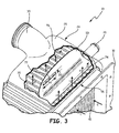
- Fig. 3 shows dual heat exchanger 10, including primary heat exchanger 12, ram inlet flange 16, and header 24.
- cold air flow C entering cold fluid inlet 40 is visible, as is hot fluid flow H exiting hot fluid outlet 48 of primary heat exchanger 12.
- the corner at which cold fluid inlet 40 and hot fluid outlet 48 intersect is cold-cold corner 56, as described previously with respect to Fig. 2 .
- Fig. 3 also shows header 24, including housing 26, OBIGGS outlet 28, and primary heat exchange outlet 30.
- housing 26 is partially cut away to show baffle 50 and closure bars 70 of the cold fluid circuit, which block cold fluid flow C from entering first cavity 74 and second cavity 76.
- Baffle 50 defines an aperture, slot 72.
- Baffle 50 is shaped to split hot fluid flow H exiting hot fluid outlet 48.
- the portion of hot fluid flow H exiting hot fluid outlet 48 closest to cold-cold corner 56 is diverted to first cavity 74.
- the remainder of hot fluid flow H exiting hot fluid outlet 48 is routed to second cavity 76.
- Slot 72 allows fluid flow from first cavity 74 to second cavity 76.
- OBIGGS outlet 28 is positioned to receive fluid from first cavity 74, whereas primary heat exchange outlet 30 is positioned to receive fluid from second cavity 76.
- Baffle 50 includes slot 72, which is an aperture positioned within baffle 50 to allow fluid flow from first cavity 74 to second cavity 76.
- Slot 72 is configured to be small enough to maintain a level of thermal separation between first cavity 74 and second cavity 76. If slot 72 is too large, heat may be convectively transferred from second cavity 76 to first cavity 74, warming the fluid within first cavity 74 and exceeding a desired temperature therein. Conversely, slot 72 is configured to be large enough to permit flow from first cavity 74 to second cavity 76 when fluid ingress to first cavity 74 from hot fluid flow H exceeds fluid egress to OBIGGS outlet 28.
- Slot 72 is defined by slot width D1 and slot height D2. In the embodiment shown in Fig.3 , slot 72 is a rectangular aperture with rounded corners. In particular, in the embodiment shown in Fig. 3 , slot width D1 is between 6.9and 7.0 cm, and slot height D2 is between 1.2 and 1.3 cm.
- slot 72 may be irregularly shaped or positioned elsewhere on baffle 50. Alternate geometries, sizes, and positions are possible that permit sufficient flow from first cavity 74 to second cavity 76 while maintaining a desired level of thermal separation therebetween.
- first cavity 74 is positioned to receive hot fluid flow H from the portion of heat exchanger 12 closest to cold-cold corner 56, the portion of hot fluid flow H routed to first cavity 74 by baffle 50 is cooler than the portion of hot fluid flow H routed to second cavity 76 by baffle 50. Additionally, because OBIGGS outlet 28 is positioned to receive fluid from first cavity 74 and primary heat exchange outlet 30 is positioned to receive fluid from second cavity 76, the fluid transferred to OBIGGS outlet 28 is cooler than the fluid transferred to primary heat exchange outlet 30.
- Baffle 50 may route more of cooled hot fluid flow H to first cavity 74 than is routed through OBIGGS outlet 28. Thus, some air may be routed through slot 72 from first cavity 74 to second cavity 76.
- Fig. 4 is a cross-sectional view of header 24 along line 4-4 of Fig. 1 .
- Hot fluid flow H is shown entering first cavity 74 and second cavity 76 between heat exchanger 12 and housing 26.
- Baffle 50 separates first cavity 74 from second cavity 76.
- the hot fluid flow H closest to cold-cold corner 56 is routed to first cavity 74 by baffle 50.
- Fig. 4 further illustrates various dimensions of baffle 50, including slot height D2, slot clearance D3, offset length D4, offset height D5, and aperture width D6.
- First cavity 74 feeds OBIGGS outlet 28, second cavity 76 feeds primary heat exchange outlet 30, and slot 72 allows for fluid flow along alternate flowpath 52 through baffle 50.
- Slot 72 defines slot height D2, as previously described with respect to Fig. 3 .
- Slot clearance D3 is the distance between the lowest edge of baffle 50 defined by dimension D5 and the lower boundary of slot 72. The lowest edge of baffle 50 is typically spaced from hot fluid outlet 48 by a small offset. In the embodiment shown in Fig. 4 , this offset is less than 0.64 cm.
- Slot clearance D3 is configured to position slot 72 to maintain a desired air flow pattern during operation.
- slot clearance D3 is between 5.2 and 5.3 cm.
- Offset length D4 is the length of a jog in baffle 50. Offset length D4 is configured to define the relative sizes of first cavity 74 and second cavity 76. Offset length D4 positions baffle 50 in proximity to cold-cold corner 56 while also positioning OBIGGS outlet 28 to be fed by first cavity 74. In the embodiment shown in Fig. 4 , offset length D4 is between 4.0 and 4.2 cm.
- Offset height D5 is the distance along baffle 50 from its closest point to hot fluid outlet 48 to the beginning of the jog defined by offset length D4. Offset height D5 is also configured to define the relative sizes of first cavity 74 and second cavity 76. Offset height D5 positions baffle 50 such that OBIGGS outlet 28 is fed by first cavity 74. In the embodiment shown in Fig. 4 , offset height D5 is between 0.8and 0.9 cm.
- Baffle 50 is separated from cold-cold corner 56 by an aperture width D6.
- Aperture width D6 defines the quantity of hot fluid flow H that is routed to first cavity 74. If aperture width D6 were to be enlarged, the portion of hot fluid flow H routed to first cavity 74 would become warmer. If aperture width D6 is sufficiently enlarged, the temperature of the portion of hot fluid flow H routed to first cavity 74 may exceed a desired threshold for fluid routed to OBIGGS outlet 28, which is fed by first cavity 74.
- aperture width D6 is between 1.5 and 1.6 cm.
- first cavity 74 and second cavity 76 The characteristics of fluid flow between first cavity 74 and second cavity 76 via alternate flowpath 52 are set by the relative sizes of slot width D1 ( Fig. 3 ) and slot height D2.
- the relative size and positions of first cavity 74 and second cavity 76 are defined by slot clearance D3, offset length D4, offset height D5, and aperture width D6.
- a heat exchanger includes a hot fluid inlet, a hot fluid outlet, a cold fluid inlet, and a cold fluid outlet.
- the heat exchanger also has a header connected to the hot fluid outlet.
- the header includes a housing and a baffle separating a first cavity from a second cavity within the housing.
- An On-Board Inert Gas Generation System (OBIGGS) outlet is defined by the housing adjacent to the first cavity.
- a primary outlet is defined by the housing adjacent to the second cavity.
- OBIGGS On-Board Inert Gas Generation System
- the heat exchanger of the preceding paragraph can optionally include, additionally and/or alternatively, any one or more of the following features, configurations and/or additional components:
- the baffle may define a slot such that the first fluid positioned in the first cavity is in fluid communication with a second fluid positioned in the second cavity via an alternate flowpath.
- the heat exchanger may be a cross-flow heat exchanger.
- the first cavity may be arranged adjacent to a cold-cold corner.
- An aperture width between the baffle and the cold-corner may be between 1.5 and 1.6 cm.
- the OBIGGS outlet may be positioned to receive a fluid from the first cavity that has a temperature of less than 99°C.
- the heat exchanger may be a primary heat exchanger of a dual heat exchange system.
- a heat exchange system in another embodiment, includes a cold fluid circuit for routing a cold fluid sequentially through a ram air inlet, a cold fluid inlet of a heat exchanger, and a cold fluid outlet of the heat exchanger.
- a hot fluid circuit for routing a hot fluid includes a bleed air valve, a hot fluid inlet of the heat exchanger, a hot fluid outlet of the heat exchanger, and a header.
- the header includes a first cavity and a second cavity defined within a housing and separated by a baffle.
- the heat exchange system of the preceding paragraph can optionally include, additionally and/or alternatively, any one or more of the following features, configurations and/or additional components:
- a method in another embodiment, includes routing a hot fluid from a bleed valve to a hot fluid inlet of a heat exchanger. Hot fluid is routed from the heat exchanger to a hot fluid outlet to cool the hot fluid. The hot fluid is separated at the hot fluid outlet into a first cavity and a second cavity. The hot fluid is routed from the first cavity to an OBIGGS system, and from the second cavity to a compressor.
- the method of the preceding paragraph can optionally include, additionally and/or alternatively, any one or more of the following steps, features, configurations and/or additional components:
Landscapes
- Engineering & Computer Science (AREA)
- Physics & Mathematics (AREA)
- Thermal Sciences (AREA)
- Mechanical Engineering (AREA)
- General Engineering & Computer Science (AREA)
- Health & Medical Sciences (AREA)
- General Health & Medical Sciences (AREA)
- Pulmonology (AREA)
- Aviation & Aerospace Engineering (AREA)
- Heat-Exchange Devices With Radiators And Conduit Assemblies (AREA)
Abstract
Description
- This invention was made with government support under Contract No. N00019-06-C-0081 awarded by the United States Navy. The government has certain rights in the invention.
- Inerting systems are used on board aircraft to reduce the volatility of fuel tanks. One type of inerting system, the On-Board Gas Generation System (OBIGGS), is used in aircraft to provide a gas with higher nitrogen levels and lower oxygen levels than ambient air to the head space of fuel tanks. OBIGGS and other inerting systems often require air input within a specific temperature range.
- Heat exchangers may be used to transfer heat between fluids. Various types of heat exchangers are known, including cross-flow, counter-flow, plate-and-pin, plate-shell, and others. In a cross-flow heat exchanger, the fluids travel roughly perpendicular to one another through the exchanger.
- A heat exchange system includes a cold fluid circuit and a hot fluid circuit. The cold fluid circuit is configured to route a cold fluid sequentially though a ram air inlet, a cold fluid inlet of a heat exchanger, and a cold fluid outlet of the heat exchanger. The hot fluid circuit is configured to route a hot fluid sequentially through a bleed air valve, a hot fluid inlet of the heat exchanger, a hot fluid outlet of the heat exchanger, and a header having a first cavity and a second cavity defined within a housing and separated by a baffle.
-
-
Fig. 1 is a perspective view of a dual heat exchanger with a header. -
Fig. 2 is a schematic view of a cross-flow heat exchanger having a baffle. -
Fig. 3 is a perspective view of the header ofFig. 1 , with a portion broken away to show a baffle. -
Fig. 4 is a cross-sectional view of the header ofFig. 1 along line 4-4. - The header described in the following figures is split into two cavities by a baffle. The baffle is arranged at the hot fluid outlet of a heat exchanger such that a temperature differential exists between the two cavities. An On-Board Inert Gas Generation System (OBIGGS) is connected to the cooler of the two cavities, and a primary outlet is connected to the warmer cavity. A slot in the baffle allows fluid flow from the cooler cavity in the event that the OBIGGS system is shut off, or when the heat exchanger is passing more air to the cooler cavity than is required by the OBIGGS.
-
Fig. 1 is a perspective view of dualheat exchange component 10. Dualheat exchange component 10 includesprimary heat exchanger 12,secondary heat exchanger 14,ram inlet flange 16,ram exhaust outlet 18, and air cyclemachine fan outlet 20.Primary heat exchanger 12 includes primarybleed inlet 22 andheader 24.Header 24 includeshousing 26, OBIGGSoutlet 28, and primaryheat exchanger outlet 30. - Dual
heat exchange component 10 is a part of an air handling system used in conjunction with a gas turbine engine (not shown).Primary heat exchanger 12 andsecondary heat exchanger 14 are used to transfer heat from working fluids in the gas turbine engine to relatively cooler ram air. Raminlet flange 16 is used to attachprimary heat exchanger 12 andsecondary heat exchanger 14 to an inlet particle separator (not shown), which receives ram air from outside the gas turbine engine, for example at a ram air scoop. The ram air received in this way is used as the cooling air flow inprimary heat exchanger 12 andsecondary heat exchanger 14. - Ram
exhaust outlet 18 and air cyclemachine fan outlet 20 are parts of heat exchange systems related toprimary heat exchanger 12 andsecondary heat exchanger 14. The availability of ram air is typically related to the air velocity of an aircraft, for example by way of a ram air scoop. Ramexhaust outlet 18 is coupled with a ram air fan (not shown), and is used to provide fluid flow acrossprimary heat exchanger 12 andsecondary heat exchanger 14. A ram air fan may be used to draw air throughprimary heat exchanger 12 when ram air is not available, for example when the aircraft is on the ground. - Air cycle
machine fan outlet 20 is coupled with the fan section of an air cycle machine (not shown). An air cycle machine may be used to condition air for use in the environmental control system of an aircraft associated with the gas turbine engine. Air passing through air cyclemachine fan outlet 20 may be cooled insecondary heat exchanger 14 before being routed to the cabin of the aircraft. - Primary bleed
inlet 22 is positioned to route bleed air from the bleed valve of the associated gas turbine engine toprimary heat exchanger 12. Bleed air of an operating gas turbine engine is much hotter than ram air due to compression and shear heating upstream of the bleed valve. For example, bleed air may be between 250°C or higher, whereas ram air is substantially the same temperature as ambient conditions, often between -55 and 50°C.Primary heat exchanger 12 is used to transfer heat from air supplied via primary bleedinlet 22 to ram air. - Bleed air that has been cooled is routed out of
primary heat exchanger 12 toheader 24.Header 24 is positioned at hot fluid outlet 48 (Fig. 2 ) and receives the cooled bleed air.Housing 26 is attached toprimary heat exchanger 12, and OBIGGSoutlet 28 is defined inhousing 26 to provide cooled bleed air to the OBIGGS. Primaryheat exchange outlet 30 is also defined inhousing 26, and provides cooled bleed air to other components of the gas turbine engine. - Because OBIGGS
outlet 28 and primaryheat exchange outlet 30 route cooled bleed air to different destinations, the desired temperature of cooled bleed air routed to OBIGGSoutlet 28 may be different from the desired temperature of cooled bleed air routed to primaryheat exchange outlet 30. In the embodiment shown inFig. 1 , OBIGGSoutlet 28 is configured to deliver fluid at 99°C or lower to an attached OBIGGS system (not shown). -
Fig. 2 is a schematic view of the fluid flowpaths of cold air flow C and hot air flow H throughprimary heat exchanger 12 ofFig. 1 .Fig. 2 illustrates the flowpaths of these two separate fluid circuits through many of the components previously listed with reference toFig. 1 . - As shown in
Fig. 2 , cold fluid (such as ram air) is routed sequentially throughcold fluid inlet 40,heat exchange region 42, andcold fluid outlet 44. Hot fluid (such as fluid from a bleed valve of a gas turbine engine) is routed sequentially throughhot fluid inlet 46,heat exchange region 42, andhot fluid outlet 48. Baffle 50 diverts cooled hot fluid withinheader 24 to OBIGGSoutlet 28 or primaryheat exchanger outlet 30.Alternate flowpath 52 allows some fluid flow from OBIGGSoutlet 28 to primaryheat exchange outlet 30, as indicated by the arrow. -
Heat exchanger region 42 facilitates heat transfer from the hot fluid to the cold fluid without intermixing the two fluids.Heat exchange region 42 is a cross-flow arrangement, in which hot fluid and cold fluid are routed between adjacent, parallel plates (not shown). As hot fluid crossesheat exchange region 42 fromhot fluid inlet 46 tohot fluid outlet 48 it is cooled by conductive heat transfer through the plates. Likewise, as cold fluid crossesheat exchange region 42 from cold fluid inlet 40 tocold fluid outlet 44 it is warmed. Thus, the hottest corner ofheat exchange region 42 is found at the corner adjacent tohot fluid inlet 46 andcold fluid outlet 44. This corner is known as hot-hot corner 54. Likewise, the coldest corner ofheat exchanger region 42 is found at the corner adjacent tohot fluid outlet 48 andcold fluid inlet 40. This corner is known as cold-cold corner 56. The corner adjacent tohot fluid inlet 46 andcold fluid inlet 40 is hot-cold corner 58, and the corner adjacent tohot fluid outlet 48 andcold fluid outlet 44 is cold-hot corner 60. - Baffle 50 separates cooled hot fluid flow H at
hot fluid outlet 48 such that the portion of hot fluid flow H closest to cold-cold corner 56 is routed to OBIGGSoutlet 28, and the remainder of cooled hot fluid flow H athot fluid outlet 48 is routed to primaryheat exchanger outlet 30. Because of the cross-fluid flow and temperature gradient from cold-cold corner 56 to cold-hot corner 60, hot fluid flow H routed toOBIGGS outlet 28 bybaffle 50 is relatively colder than cooled hot fluid flow H routed to primaryheat exchanger outlet 30. -
Alternate flowpath 52 is positioned to allow fluid communication fromOBIGGS outlet 28 to primaryheat exchanger outlet 30. This may be desirable in situations where the OBIGGS does not require as much fluid as is provided toOBIGGS outlet 28, such as when the OBIGGS is shut off. As indicated by the arrow, fluid flow throughalternate flowpath 52 is unidirectional. -
Fig. 3 showsdual heat exchanger 10, includingprimary heat exchanger 12,ram inlet flange 16, andheader 24. As seen inFig. 3 , cold air flow C entering coldfluid inlet 40 is visible, as is hot fluid flow H exitinghot fluid outlet 48 ofprimary heat exchanger 12. The corner at whichcold fluid inlet 40 and hotfluid outlet 48 intersect is cold-cold corner 56, as described previously with respect toFig. 2 .Fig. 3 also showsheader 24, includinghousing 26,OBIGGS outlet 28, and primaryheat exchange outlet 30. As shown inFig. 3 ,housing 26 is partially cut away to showbaffle 50 and closure bars 70 of the cold fluid circuit, which block cold fluid flow C from enteringfirst cavity 74 andsecond cavity 76.Baffle 50 defines an aperture,slot 72. -
Baffle 50 is shaped to split hot fluid flow H exitinghot fluid outlet 48. The portion of hot fluid flow H exitinghot fluid outlet 48 closest to cold-cold corner 56 is diverted tofirst cavity 74. The remainder of hot fluid flow H exitinghot fluid outlet 48 is routed tosecond cavity 76.Slot 72 allows fluid flow fromfirst cavity 74 tosecond cavity 76.OBIGGS outlet 28 is positioned to receive fluid fromfirst cavity 74, whereas primaryheat exchange outlet 30 is positioned to receive fluid fromsecond cavity 76. -
Baffle 50 includesslot 72, which is an aperture positioned withinbaffle 50 to allow fluid flow fromfirst cavity 74 tosecond cavity 76.Slot 72 is configured to be small enough to maintain a level of thermal separation betweenfirst cavity 74 andsecond cavity 76. Ifslot 72 is too large, heat may be convectively transferred fromsecond cavity 76 tofirst cavity 74, warming the fluid withinfirst cavity 74 and exceeding a desired temperature therein. Conversely,slot 72 is configured to be large enough to permit flow fromfirst cavity 74 tosecond cavity 76 when fluid ingress tofirst cavity 74 from hot fluid flow H exceeds fluid egress toOBIGGS outlet 28.Slot 72 is defined by slot width D1 and slot height D2. In the embodiment shown inFig.3 ,slot 72 is a rectangular aperture with rounded corners. In particular, in the embodiment shown inFig. 3 , slot width D1 is between 6.9and 7.0 cm, and slot height D2 is between 1.2 and 1.3 cm. - In alternative embodiments,
slot 72 may be irregularly shaped or positioned elsewhere onbaffle 50. Alternate geometries, sizes, and positions are possible that permit sufficient flow fromfirst cavity 74 tosecond cavity 76 while maintaining a desired level of thermal separation therebetween. - Because
first cavity 74 is positioned to receive hot fluid flow H from the portion ofheat exchanger 12 closest to cold-cold corner 56, the portion of hot fluid flow H routed tofirst cavity 74 bybaffle 50 is cooler than the portion of hot fluid flow H routed tosecond cavity 76 bybaffle 50. Additionally, becauseOBIGGS outlet 28 is positioned to receive fluid fromfirst cavity 74 and primaryheat exchange outlet 30 is positioned to receive fluid fromsecond cavity 76, the fluid transferred toOBIGGS outlet 28 is cooler than the fluid transferred to primaryheat exchange outlet 30. -
Baffle 50 may route more of cooled hot fluid flow H tofirst cavity 74 than is routed throughOBIGGS outlet 28. Thus, some air may be routed throughslot 72 fromfirst cavity 74 tosecond cavity 76. -
Fig. 4 is a cross-sectional view ofheader 24 along line 4-4 ofFig. 1 . Hot fluid flow H is shown enteringfirst cavity 74 andsecond cavity 76 betweenheat exchanger 12 andhousing 26.Baffle 50 separatesfirst cavity 74 fromsecond cavity 76. The hot fluid flow H closest to cold-cold corner 56 is routed tofirst cavity 74 bybaffle 50.Fig. 4 further illustrates various dimensions ofbaffle 50, including slot height D2, slot clearance D3, offset length D4, offset height D5, and aperture width D6. -
First cavity 74 feedsOBIGGS outlet 28,second cavity 76 feeds primaryheat exchange outlet 30, andslot 72 allows for fluid flow alongalternate flowpath 52 throughbaffle 50.Slot 72 defines slot height D2, as previously described with respect toFig. 3 . Slot clearance D3 is the distance between the lowest edge ofbaffle 50 defined by dimension D5 and the lower boundary ofslot 72. The lowest edge ofbaffle 50 is typically spaced from hotfluid outlet 48 by a small offset. In the embodiment shown inFig. 4 , this offset is less than 0.64 cm. Slot clearance D3 is configured to positionslot 72 to maintain a desired air flow pattern during operation. By positioningslot 72 further from cold-cold corner 56 thanOBIGGS outlet 28, the temperature of hot air flow H that is routed toOBIGGS outlet 28 in normal operating conditions is reduced. In the embodiment shown inFig. 4 , slot clearance D3 is between 5.2 and 5.3 cm. - Offset length D4 is the length of a jog in
baffle 50. Offset length D4 is configured to define the relative sizes offirst cavity 74 andsecond cavity 76. Offset length D4 positions baffle 50 in proximity to cold-cold corner 56 while also positioningOBIGGS outlet 28 to be fed byfirst cavity 74. In the embodiment shown inFig. 4 , offset length D4 is between 4.0 and 4.2 cm. - Offset height D5 is the distance along
baffle 50 from its closest point to hotfluid outlet 48 to the beginning of the jog defined by offset length D4. Offset height D5 is also configured to define the relative sizes offirst cavity 74 andsecond cavity 76. Offset height D5 positions baffle 50 such thatOBIGGS outlet 28 is fed byfirst cavity 74. In the embodiment shown inFig. 4 , offset height D5 is between 0.8and 0.9 cm. -
Baffle 50 is separated from cold-cold corner 56 by an aperture width D6. Aperture width D6 defines the quantity of hot fluid flow H that is routed tofirst cavity 74. If aperture width D6 were to be enlarged, the portion of hot fluid flow H routed tofirst cavity 74 would become warmer. If aperture width D6 is sufficiently enlarged, the temperature of the portion of hot fluid flow H routed tofirst cavity 74 may exceed a desired threshold for fluid routed toOBIGGS outlet 28, which is fed byfirst cavity 74. - Conversely, if aperture width D6 were to be narrowed, the portion of hot fluid flow H routed to
first cavity 74 would become cooler. However, with sufficiently narrow aperture width D6, fluid ingress tofirst cavity 74 may become too low to supplyOBIGGS outlet 28. In that case, fluid flow direction across slot 72 (Fig. 3 ) may become reversed, and fluid would travel fromsecond cavity 76 tofirst cavity 74, in the opposite direction ofalternate flowpath 52. Because the portion of hot fluid flow H directed tosecond cavity 76 has been routed through a portion of hotfluid outlet 48 that is distant from cold-cold corner 56, the result of narrowing aperture width D6 may also be increasing the temperature of fluid positioned infirst cavity 74 above a predetermined threshold for fluid routed toOBIGGS outlet 28. In the embodiment shown inFig. 4 , aperture width D6 is between 1.5 and 1.6 cm. - The characteristics of fluid flow between
first cavity 74 andsecond cavity 76 viaalternate flowpath 52 are set by the relative sizes of slot width D1 (Fig. 3 ) and slot height D2. The relative size and positions offirst cavity 74 andsecond cavity 76 are defined by slot clearance D3, offset length D4, offset height D5, and aperture width D6. - The following are non-exclusive descriptions of possible embodiments of the present invention.
- A heat exchanger includes a hot fluid inlet, a hot fluid outlet, a cold fluid inlet, and a cold fluid outlet. The heat exchanger also has a header connected to the hot fluid outlet. The header includes a housing and a baffle separating a first cavity from a second cavity within the housing. An On-Board Inert Gas Generation System (OBIGGS) outlet is defined by the housing adjacent to the first cavity. A primary outlet is defined by the housing adjacent to the second cavity.
- The heat exchanger of the preceding paragraph can optionally include, additionally and/or alternatively, any one or more of the following features, configurations and/or additional components:
- The baffle may define a slot such that the first fluid positioned in the first cavity is in fluid communication with a second fluid positioned in the second cavity via an alternate flowpath. The heat exchanger may be a cross-flow heat exchanger. The first cavity may be arranged adjacent to a cold-cold corner. An aperture width between the baffle and the cold-corner may be between 1.5 and 1.6 cm. The OBIGGS outlet may be positioned to receive a fluid from the first cavity that has a temperature of less than 99°C. The heat exchanger may be a primary heat exchanger of a dual heat exchange system.
- In another embodiment, a heat exchange system includes a cold fluid circuit for routing a cold fluid sequentially through a ram air inlet, a cold fluid inlet of a heat exchanger, and a cold fluid outlet of the heat exchanger. A hot fluid circuit for routing a hot fluid includes a bleed air valve, a hot fluid inlet of the heat exchanger, a hot fluid outlet of the heat exchanger, and a header. The header includes a first cavity and a second cavity defined within a housing and separated by a baffle.
- The heat exchange system of the preceding paragraph can optionally include, additionally and/or alternatively, any one or more of the following features, configurations and/or additional components:
- The heat exchanger may be configured to transfer heat from the hot fluid to the cold fluid. The heat exchanger may be a cross-flow heat exchanger. The first cavity may be configured to receive the hot fluid routed between the baffle and the cold-cold corner. The aperture width between the baffle and the cold-cold corner may be between 1.5 and 1.6 cm. The baffle may include a slot. The heat exchange system may also include an alternate flowpath from the first cavity to the second cavity via the slot.
- In another embodiment, a method includes routing a hot fluid from a bleed valve to a hot fluid inlet of a heat exchanger. Hot fluid is routed from the heat exchanger to a hot fluid outlet to cool the hot fluid. The hot fluid is separated at the hot fluid outlet into a first cavity and a second cavity. The hot fluid is routed from the first cavity to an OBIGGS system, and from the second cavity to a compressor.
- The method of the preceding paragraph can optionally include, additionally and/or alternatively, any one or more of the following steps, features, configurations and/or additional components:
- The heat exchanger may be a cross-flow heat exchanger. The first cavity and the second cavity may be separated by a baffle. The baffle may be arranged between 1.5 cm and 1.6 cm from the cold-cold corner. The method may also include diverting the hot fluid from the hot fluid outlet within an aperture width of the cold-cold corner to the first cavity, and diverting the hot fluid from the hot fluid outlet that is not within an aperture width of the cold-cold corner of the second cavity. The method may also include comprising routing the hot fluid from the first cavity to the second cavity via an alternate flowpath.
- While the invention has been described with reference to an exemplary embodiment(s), it will be understood by those skilled in the art that various changes may be made and equivalents may be substituted for elements thereof without departing from the scope of the invention. In addition, many modifications may be made to adapt a particular situation or material to the teachings of the invention without departing from the essential scope thereof. Therefore, it is intended that the invention not be limited to the particular embodiment(s) disclosed, but that the invention will include all embodiments falling within the scope of the appended claims.
Claims (15)
- A heat exchanger (12) comprising:a hot fluid inlet (46);a hot fluid outlet (48);a cold fluid inlet (40);a cold fluid outlet (44); anda header (24) connected to the hot fluid outlet (48), the header (24) comprising:a housing (26);a baffle (50) separating a first cavity (74) from a second cavity (76) within the housing (26);an On-Board Inert Gas Generation System (OBIGGS) outlet (28) adjacent to the first cavity (74); anda primary outlet (30) adjacent to the second cavity (76).
- The heat exchanger of claim 1, wherein the baffle (50) defines a slot (72) such that a first fluid positioned in the first cavity (74) is in fluid communication with a second fluid positioned in the second cavity (76) via an alternate flowpath (52).
- The heat exchanger of claim 1 or 2, wherein the heat exchanger (12) is a cross-flow heat exchanger.
- The heat exchanger of any preceding claim, wherein the first cavity (74) is arranged adjacent to a cold-cold corner (56).
- The heat exchanger of claim 4, wherein an aperture width (D6) between the baffle (50) and the cold-cold corner (56) is between 1.5 cm and 1.6 cm.
- The heat exchanger of any preceding claim, wherein the OBIGGS outlet (28) is positioned to receive a fluid from the first cavity (74) that has a temperature of less than 99°C.
- The heat exchanger of any preceding claim, wherein the heat exchanger (12) is a primary heat exchanger of a dual heat exchange system (10).
- A heat exchange system employing the heat exchanger of any preceding claim comprising:a cold fluid circuit for routing the cold fluid sequentially though:a ram air inlet;the cold fluid inlet (40) of the heat exchanger (12); andthe cold fluid outlet (44) of the heat exchanger (12); anda hot fluid circuit for routing the hot fluid sequentially through:a bleed air valve;the hot fluid inlet (46) of the heat exchanger (12);the hot fluid outlet (48) of the heat exchanger (12); andthe header (24).
- The heat exchange system of claim 8, wherein the heat exchanger (12) is configured to transfer heat from the hot fluid to the cold fluid.
- A method comprising:routing a hot fluid from a bleed valve to a hot fluid inlet (46) of a heat exchanger (12);routing the hot fluid through the heat exchanger (12) to a hot fluid outlet (48) to cool the hot fluid;separating the hot fluid at the hot fluid outlet (48) into a first cavity (74) and a second cavity (76);routing the hot fluid from the first cavity (74) to an OBIGGS system; androuting the hot fluid from the second cavity (76) to a compressor.
- The method of claim 10, wherein the heat exchanger (12) is a cross-flow heat exchanger.
- The method of claim 10 or 11, wherein the first cavity (74) and the second cavity (76) are separated by a baffle (50).
- The method of claim 12, wherein the baffle (50) is arranged between 1.5 cm and 1.6 cm from a cold-cold corner (56).
- The method of claim 13, and further comprising:diverting the hot fluid from the hot fluid outlet (48) within an aperture width of the cold-cold corner (56) to the first cavity (74); anddiverting the hot fluid from the hot fluid outlet (48) that is not within an aperture width of the cold-cold corner (50) to the second cavity (76).
- The method of any of claims 10 to 14, and further comprising routing the hot fluid from the first cavity (74) to the second cavity (76) via an alternate flowpath (52).
Applications Claiming Priority (1)
| Application Number | Priority Date | Filing Date | Title |
|---|---|---|---|
| US201361864255P | 2013-08-09 | 2013-08-09 |
Publications (2)
| Publication Number | Publication Date |
|---|---|
| EP2835312A1 true EP2835312A1 (en) | 2015-02-11 |
| EP2835312B1 EP2835312B1 (en) | 2018-01-17 |
Family
ID=50972459
Family Applications (1)
| Application Number | Title | Priority Date | Filing Date |
|---|---|---|---|
| EP14171605.0A Active EP2835312B1 (en) | 2013-08-09 | 2014-06-06 | Cold corner flow baffle |
Country Status (2)
| Country | Link |
|---|---|
| US (1) | US10107554B2 (en) |
| EP (1) | EP2835312B1 (en) |
Cited By (2)
| Publication number | Priority date | Publication date | Assignee | Title |
|---|---|---|---|---|
| EP3447431A1 (en) * | 2017-08-23 | 2019-02-27 | Hamilton Sundstrand Corporation | Heat exchanger assembly |
| CN110398164A (en) * | 2019-06-27 | 2019-11-01 | 中国船舶重工集团公司第七一九研究所 | A kind of heat exchanger |
Families Citing this family (9)
| Publication number | Priority date | Publication date | Assignee | Title |
|---|---|---|---|---|
| US10124452B2 (en) | 2013-08-09 | 2018-11-13 | Hamilton Sundstrand Corporation | Cold corner flow baffle |
| DE102014008411A1 (en) * | 2014-06-13 | 2015-12-17 | Airbus Defence and Space GmbH | Device for pre-cooling and cleaning engine bleed air |
| EP3193128B1 (en) * | 2016-01-15 | 2020-04-22 | Hamilton Sundstrand Corporation | Heat exchanger with cold corner flow baffle |
| US11396378B2 (en) * | 2018-01-24 | 2022-07-26 | Hamilton Sundstrand Corporation | ECS dual entry ram inlet plenum |
| CN108645250B (en) * | 2018-04-17 | 2024-10-18 | 陕西东明化工装备工程有限公司 | Combined efficient heat exchanger |
| US11130581B2 (en) | 2018-06-21 | 2021-09-28 | Hamilton Sundstrand Corporation | Air nozzle arrangement |
| US10730631B2 (en) | 2018-06-21 | 2020-08-04 | Hamilton Sunstrand Corporation | Air nozzle arrangement |
| US11867472B2 (en) | 2021-04-30 | 2024-01-09 | Hamilton Sundstrand Corporation | Heated header for subfreezing heat exchanger |
| CN115615221A (en) * | 2021-07-16 | 2023-01-17 | 浙江三花汽车零部件有限公司 | a heat exchanger |
Citations (3)
| Publication number | Priority date | Publication date | Assignee | Title |
|---|---|---|---|---|
| DE2753496A1 (en) * | 1977-12-01 | 1979-06-07 | Linde Ag | Heat exchanger for several fluids - with partitioned antechamber and nests of tubes in main shell |
| DE19636018A1 (en) * | 1996-09-05 | 1998-03-12 | Markus Dipl Ing Fohr | Multi-chamber heat-exchanger |
| WO2010107881A1 (en) * | 2009-03-17 | 2010-09-23 | Dow Global Technologies, Inc. | Tube-side sequentially pulsable-flow shell-and-tube heat exchanger apparatus, system, and method |
Family Cites Families (22)
| Publication number | Priority date | Publication date | Assignee | Title |
|---|---|---|---|---|
| US3994335A (en) * | 1975-03-06 | 1976-11-30 | Robertshaw Controls Company | Multizone air conditioning system |
| US4312381A (en) * | 1980-03-27 | 1982-01-26 | Aladdin Heating Corporation | Air flow damping system |
| EP0212878A1 (en) | 1985-08-08 | 1987-03-04 | Heatric Pty. Limited | Plate-type cross-flow heat exchanger |
| US5101883A (en) * | 1991-06-27 | 1992-04-07 | General Motors Corporation | Method of assembly of single and multi-zone vehicle heating and a/c systems |
| US5816315A (en) | 1995-09-13 | 1998-10-06 | Nautica Dehumidifiers, Inc. | Plate-type crossflow air-to-air heat exchanger having dual pass cooling |
| JPH09280773A (en) * | 1996-04-17 | 1997-10-31 | Sanden Corp | Liquid receiving part built-in type condenser |
| KR100565818B1 (en) * | 1996-08-12 | 2007-04-04 | 칼소닉 칸세이 가부시끼가이샤 | Integral heat exchanger |
| AU5121598A (en) | 1997-05-12 | 1998-12-08 | Norsk Hydro Asa | Heat exchanger |
| US6021042A (en) * | 1997-08-06 | 2000-02-01 | Intel Corporation | Cooling duct for a computer cooling system with redundant air moving units |
| US6161614A (en) * | 1998-03-27 | 2000-12-19 | Karmazin Products Corporation | Aluminum header construction |
| JP2004537028A (en) * | 2001-08-06 | 2004-12-09 | ノルスク・ヒドロ・アーエスアー | High pressure manifold |
| DE50213792D1 (en) * | 2001-11-08 | 2009-10-08 | Behr Gmbh & Co Kg | heat exchangers |
| US6926490B2 (en) * | 2003-01-21 | 2005-08-09 | Hamilton Sundstrand | Self-actuated bearing cooling flow shut-off valve |
| SE0303307L (en) | 2003-12-10 | 2004-10-19 | Swep Int Ab | Plate heat exchanger |
| EP1979603B1 (en) * | 2006-01-19 | 2014-03-26 | Behr GmbH & Co. KG | Device for cooling waste gas |
| US20070220900A1 (en) * | 2006-03-27 | 2007-09-27 | General Electric Company | Auxiliary gas turbine engine assembly, aircraft component and controller |
| US7905259B2 (en) * | 2006-11-15 | 2011-03-15 | Honeywell International Inc. | Advanced carbon dioxide fuel tank inerting system |
| GB2447090B (en) | 2007-03-02 | 2012-03-21 | Statoil Asa | Heat exchanger manifolds |
| DE102009053884A1 (en) * | 2009-11-20 | 2011-06-01 | Behr Gmbh & Co. Kg | Suction tube for an internal combustion engine |
| US9151539B2 (en) | 2011-04-07 | 2015-10-06 | Hamilton Sundstrand Corporation | Heat exchanger having a core angled between two headers |
| GB2499576A (en) * | 2011-11-29 | 2013-08-28 | Eaton Aerospace Ltd | Aircraft on board inert gas generation system |
| US9302778B2 (en) * | 2013-08-07 | 2016-04-05 | Hamilton Sundstrand Corporation | Dual heat exchanger fuel tank inerting system |
-
2014
- 2014-06-06 EP EP14171605.0A patent/EP2835312B1/en active Active
- 2014-06-09 US US14/299,703 patent/US10107554B2/en active Active
Patent Citations (3)
| Publication number | Priority date | Publication date | Assignee | Title |
|---|---|---|---|---|
| DE2753496A1 (en) * | 1977-12-01 | 1979-06-07 | Linde Ag | Heat exchanger for several fluids - with partitioned antechamber and nests of tubes in main shell |
| DE19636018A1 (en) * | 1996-09-05 | 1998-03-12 | Markus Dipl Ing Fohr | Multi-chamber heat-exchanger |
| WO2010107881A1 (en) * | 2009-03-17 | 2010-09-23 | Dow Global Technologies, Inc. | Tube-side sequentially pulsable-flow shell-and-tube heat exchanger apparatus, system, and method |
Cited By (4)
| Publication number | Priority date | Publication date | Assignee | Title |
|---|---|---|---|---|
| EP3447431A1 (en) * | 2017-08-23 | 2019-02-27 | Hamilton Sundstrand Corporation | Heat exchanger assembly |
| US10502503B2 (en) | 2017-08-23 | 2019-12-10 | Hamilton Sundstrand Corporation | Heat exchanger assembly |
| CN110398164A (en) * | 2019-06-27 | 2019-11-01 | 中国船舶重工集团公司第七一九研究所 | A kind of heat exchanger |
| CN110398164B (en) * | 2019-06-27 | 2024-05-24 | 中国船舶重工集团公司第七一九研究所 | Heat exchanger |
Also Published As
| Publication number | Publication date |
|---|---|
| EP2835312B1 (en) | 2018-01-17 |
| US10107554B2 (en) | 2018-10-23 |
| US20150041108A1 (en) | 2015-02-12 |
Similar Documents
| Publication | Publication Date | Title |
|---|---|---|
| US10107554B2 (en) | Cold corner flow baffle | |
| US10907546B2 (en) | Cross-stream heat exchanger | |
| EP2795083B1 (en) | Bleed air and hot section component cooling air system of a gas turbine and method | |
| US10124452B2 (en) | Cold corner flow baffle | |
| EP2710313B1 (en) | Method and apparatus for aircraft galley cooling | |
| US20100084118A1 (en) | Cooling system for aircraft electric or electronic devices | |
| KR101893807B1 (en) | Heat exchanger for vehicle | |
| CN106882390B (en) | Aircraft air-entraining precooling regenerative system | |
| EP2757343B1 (en) | Sub freezing load heat exchanger bypass | |
| EP2192286B1 (en) | Method and system for extra cooling of the coolant in a vehicle´s cooling system | |
| EP3284929B1 (en) | Heat exchanger arrangement for a gas turbine | |
| EP3549866A1 (en) | Liquid reheater heat exchanger in an air cycle system | |
| CN110014820B (en) | Cooling module | |
| EP3587268A1 (en) | Simultaneous dual engine bleed thermal management system | |
| US11199364B2 (en) | Heat exchanger | |
| US20110297352A1 (en) | Preheating device for a fluid/fluid heat exchanger of an aircraft | |
| US10488117B1 (en) | Aircraft heat exchanger defrost system | |
| EP3193128B1 (en) | Heat exchanger with cold corner flow baffle | |
| EP3760544B1 (en) | Adaptive plate-fin heat exchanger | |
| EP4008985A1 (en) | Subfreezing heat exchanger with separate melt fluid | |
| EP3054127B1 (en) | Thermal management system for gas turbine engines | |
| US20070034351A1 (en) | Heat exchanger, propulsion unit, and aircraft comprising such a propulsion unit | |
| US20140231059A1 (en) | Heat exchanger | |
| US9372019B2 (en) | Dual circuit refrigerant condenser | |
| EP3069997A1 (en) | Aircraft comprising a heat exchanger |
Legal Events
| Date | Code | Title | Description |
|---|---|---|---|
| PUAI | Public reference made under article 153(3) epc to a published international application that has entered the european phase |
Free format text: ORIGINAL CODE: 0009012 |
|
| 17P | Request for examination filed |
Effective date: 20140606 |
|
| AK | Designated contracting states |
Kind code of ref document: A1 Designated state(s): AL AT BE BG CH CY CZ DE DK EE ES FI FR GB GR HR HU IE IS IT LI LT LU LV MC MK MT NL NO PL PT RO RS SE SI SK SM TR |
|
| AX | Request for extension of the european patent |
Extension state: BA ME |
|
| R17P | Request for examination filed (corrected) |
Effective date: 20150811 |
|
| RBV | Designated contracting states (corrected) |
Designated state(s): AL AT BE BG CH CY CZ DE DK EE ES FI FR GB GR HR HU IE IS IT LI LT LU LV MC MK MT NL NO PL PT RO RS SE SI SK SM TR |
|
| GRAP | Despatch of communication of intention to grant a patent |
Free format text: ORIGINAL CODE: EPIDOSNIGR1 |
|
| STAA | Information on the status of an ep patent application or granted ep patent |
Free format text: STATUS: GRANT OF PATENT IS INTENDED |
|
| INTG | Intention to grant announced |
Effective date: 20170214 |
|
| GRAJ | Information related to disapproval of communication of intention to grant by the applicant or resumption of examination proceedings by the epo deleted |
Free format text: ORIGINAL CODE: EPIDOSDIGR1 |
|
| STAA | Information on the status of an ep patent application or granted ep patent |
Free format text: STATUS: REQUEST FOR EXAMINATION WAS MADE |
|
| INTC | Intention to grant announced (deleted) | ||
| GRAP | Despatch of communication of intention to grant a patent |
Free format text: ORIGINAL CODE: EPIDOSNIGR1 |
|
| STAA | Information on the status of an ep patent application or granted ep patent |
Free format text: STATUS: GRANT OF PATENT IS INTENDED |
|
| INTG | Intention to grant announced |
Effective date: 20170825 |
|
| GRAS | Grant fee paid |
Free format text: ORIGINAL CODE: EPIDOSNIGR3 |
|
| GRAA | (expected) grant |
Free format text: ORIGINAL CODE: 0009210 |
|
| STAA | Information on the status of an ep patent application or granted ep patent |
Free format text: STATUS: THE PATENT HAS BEEN GRANTED |
|
| AK | Designated contracting states |
Kind code of ref document: B1 Designated state(s): AL AT BE BG CH CY CZ DE DK EE ES FI FR GB GR HR HU IE IS IT LI LT LU LV MC MK MT NL NO PL PT RO RS SE SI SK SM TR |
|
| REG | Reference to a national code |
Ref country code: GB Ref legal event code: FG4D |
|
| REG | Reference to a national code |
Ref country code: CH Ref legal event code: EP |
|
| REG | Reference to a national code |
Ref country code: IE Ref legal event code: FG4D |
|
| REG | Reference to a national code |
Ref country code: AT Ref legal event code: REF Ref document number: 964221 Country of ref document: AT Kind code of ref document: T Effective date: 20180215 |
|
| REG | Reference to a national code |
Ref country code: DE Ref legal event code: R096 Ref document number: 602014019984 Country of ref document: DE |
|
| REG | Reference to a national code |
Ref country code: NL Ref legal event code: MP Effective date: 20180117 |
|
| REG | Reference to a national code |
Ref country code: FR Ref legal event code: PLFP Year of fee payment: 5 |
|
| REG | Reference to a national code |
Ref country code: LT Ref legal event code: MG4D |
|
| REG | Reference to a national code |
Ref country code: AT Ref legal event code: MK05 Ref document number: 964221 Country of ref document: AT Kind code of ref document: T Effective date: 20180117 |
|
| PG25 | Lapsed in a contracting state [announced via postgrant information from national office to epo] |
Ref country code: NL Free format text: LAPSE BECAUSE OF FAILURE TO SUBMIT A TRANSLATION OF THE DESCRIPTION OR TO PAY THE FEE WITHIN THE PRESCRIBED TIME-LIMIT Effective date: 20180117 |
|
| PG25 | Lapsed in a contracting state [announced via postgrant information from national office to epo] |
Ref country code: CY Free format text: LAPSE BECAUSE OF FAILURE TO SUBMIT A TRANSLATION OF THE DESCRIPTION OR TO PAY THE FEE WITHIN THE PRESCRIBED TIME-LIMIT Effective date: 20180117 Ref country code: LT Free format text: LAPSE BECAUSE OF FAILURE TO SUBMIT A TRANSLATION OF THE DESCRIPTION OR TO PAY THE FEE WITHIN THE PRESCRIBED TIME-LIMIT Effective date: 20180117 Ref country code: FI Free format text: LAPSE BECAUSE OF FAILURE TO SUBMIT A TRANSLATION OF THE DESCRIPTION OR TO PAY THE FEE WITHIN THE PRESCRIBED TIME-LIMIT Effective date: 20180117 Ref country code: HR Free format text: LAPSE BECAUSE OF FAILURE TO SUBMIT A TRANSLATION OF THE DESCRIPTION OR TO PAY THE FEE WITHIN THE PRESCRIBED TIME-LIMIT Effective date: 20180117 Ref country code: ES Free format text: LAPSE BECAUSE OF FAILURE TO SUBMIT A TRANSLATION OF THE DESCRIPTION OR TO PAY THE FEE WITHIN THE PRESCRIBED TIME-LIMIT Effective date: 20180117 Ref country code: NO Free format text: LAPSE BECAUSE OF FAILURE TO SUBMIT A TRANSLATION OF THE DESCRIPTION OR TO PAY THE FEE WITHIN THE PRESCRIBED TIME-LIMIT Effective date: 20180417 |
|
| PG25 | Lapsed in a contracting state [announced via postgrant information from national office to epo] |
Ref country code: PL Free format text: LAPSE BECAUSE OF FAILURE TO SUBMIT A TRANSLATION OF THE DESCRIPTION OR TO PAY THE FEE WITHIN THE PRESCRIBED TIME-LIMIT Effective date: 20180117 Ref country code: RS Free format text: LAPSE BECAUSE OF FAILURE TO SUBMIT A TRANSLATION OF THE DESCRIPTION OR TO PAY THE FEE WITHIN THE PRESCRIBED TIME-LIMIT Effective date: 20180117 Ref country code: AT Free format text: LAPSE BECAUSE OF FAILURE TO SUBMIT A TRANSLATION OF THE DESCRIPTION OR TO PAY THE FEE WITHIN THE PRESCRIBED TIME-LIMIT Effective date: 20180117 Ref country code: BG Free format text: LAPSE BECAUSE OF FAILURE TO SUBMIT A TRANSLATION OF THE DESCRIPTION OR TO PAY THE FEE WITHIN THE PRESCRIBED TIME-LIMIT Effective date: 20180417 Ref country code: GR Free format text: LAPSE BECAUSE OF FAILURE TO SUBMIT A TRANSLATION OF THE DESCRIPTION OR TO PAY THE FEE WITHIN THE PRESCRIBED TIME-LIMIT Effective date: 20180418 Ref country code: LV Free format text: LAPSE BECAUSE OF FAILURE TO SUBMIT A TRANSLATION OF THE DESCRIPTION OR TO PAY THE FEE WITHIN THE PRESCRIBED TIME-LIMIT Effective date: 20180117 Ref country code: IS Free format text: LAPSE BECAUSE OF FAILURE TO SUBMIT A TRANSLATION OF THE DESCRIPTION OR TO PAY THE FEE WITHIN THE PRESCRIBED TIME-LIMIT Effective date: 20180517 Ref country code: SE Free format text: LAPSE BECAUSE OF FAILURE TO SUBMIT A TRANSLATION OF THE DESCRIPTION OR TO PAY THE FEE WITHIN THE PRESCRIBED TIME-LIMIT Effective date: 20180117 |
|
| REG | Reference to a national code |
Ref country code: DE Ref legal event code: R097 Ref document number: 602014019984 Country of ref document: DE |
|
| PG25 | Lapsed in a contracting state [announced via postgrant information from national office to epo] |
Ref country code: AL Free format text: LAPSE BECAUSE OF FAILURE TO SUBMIT A TRANSLATION OF THE DESCRIPTION OR TO PAY THE FEE WITHIN THE PRESCRIBED TIME-LIMIT Effective date: 20180117 Ref country code: RO Free format text: LAPSE BECAUSE OF FAILURE TO SUBMIT A TRANSLATION OF THE DESCRIPTION OR TO PAY THE FEE WITHIN THE PRESCRIBED TIME-LIMIT Effective date: 20180117 Ref country code: EE Free format text: LAPSE BECAUSE OF FAILURE TO SUBMIT A TRANSLATION OF THE DESCRIPTION OR TO PAY THE FEE WITHIN THE PRESCRIBED TIME-LIMIT Effective date: 20180117 Ref country code: IT Free format text: LAPSE BECAUSE OF FAILURE TO SUBMIT A TRANSLATION OF THE DESCRIPTION OR TO PAY THE FEE WITHIN THE PRESCRIBED TIME-LIMIT Effective date: 20180117 |
|
| PLBE | No opposition filed within time limit |
Free format text: ORIGINAL CODE: 0009261 |
|
| STAA | Information on the status of an ep patent application or granted ep patent |
Free format text: STATUS: NO OPPOSITION FILED WITHIN TIME LIMIT |
|
| PG25 | Lapsed in a contracting state [announced via postgrant information from national office to epo] |
Ref country code: SK Free format text: LAPSE BECAUSE OF FAILURE TO SUBMIT A TRANSLATION OF THE DESCRIPTION OR TO PAY THE FEE WITHIN THE PRESCRIBED TIME-LIMIT Effective date: 20180117 Ref country code: CZ Free format text: LAPSE BECAUSE OF FAILURE TO SUBMIT A TRANSLATION OF THE DESCRIPTION OR TO PAY THE FEE WITHIN THE PRESCRIBED TIME-LIMIT Effective date: 20180117 Ref country code: SM Free format text: LAPSE BECAUSE OF FAILURE TO SUBMIT A TRANSLATION OF THE DESCRIPTION OR TO PAY THE FEE WITHIN THE PRESCRIBED TIME-LIMIT Effective date: 20180117 Ref country code: DK Free format text: LAPSE BECAUSE OF FAILURE TO SUBMIT A TRANSLATION OF THE DESCRIPTION OR TO PAY THE FEE WITHIN THE PRESCRIBED TIME-LIMIT Effective date: 20180117 |
|
| 26N | No opposition filed |
Effective date: 20181018 |
|
| REG | Reference to a national code |
Ref country code: DE Ref legal event code: R119 Ref document number: 602014019984 Country of ref document: DE |
|
| REG | Reference to a national code |
Ref country code: CH Ref legal event code: PL |
|
| PG25 | Lapsed in a contracting state [announced via postgrant information from national office to epo] |
Ref country code: SI Free format text: LAPSE BECAUSE OF FAILURE TO SUBMIT A TRANSLATION OF THE DESCRIPTION OR TO PAY THE FEE WITHIN THE PRESCRIBED TIME-LIMIT Effective date: 20180117 |
|
| REG | Reference to a national code |
Ref country code: BE Ref legal event code: MM Effective date: 20180630 |
|
| REG | Reference to a national code |
Ref country code: IE Ref legal event code: MM4A |
|
| PG25 | Lapsed in a contracting state [announced via postgrant information from national office to epo] |
Ref country code: MC Free format text: LAPSE BECAUSE OF FAILURE TO SUBMIT A TRANSLATION OF THE DESCRIPTION OR TO PAY THE FEE WITHIN THE PRESCRIBED TIME-LIMIT Effective date: 20180117 Ref country code: LU Free format text: LAPSE BECAUSE OF NON-PAYMENT OF DUE FEES Effective date: 20180606 |
|
| PG25 | Lapsed in a contracting state [announced via postgrant information from national office to epo] |
Ref country code: CH Free format text: LAPSE BECAUSE OF NON-PAYMENT OF DUE FEES Effective date: 20180630 Ref country code: IE Free format text: LAPSE BECAUSE OF NON-PAYMENT OF DUE FEES Effective date: 20180606 Ref country code: LI Free format text: LAPSE BECAUSE OF NON-PAYMENT OF DUE FEES Effective date: 20180630 Ref country code: DE Free format text: LAPSE BECAUSE OF NON-PAYMENT OF DUE FEES Effective date: 20190101 |
|
| PG25 | Lapsed in a contracting state [announced via postgrant information from national office to epo] |
Ref country code: BE Free format text: LAPSE BECAUSE OF NON-PAYMENT OF DUE FEES Effective date: 20180630 |
|
| PG25 | Lapsed in a contracting state [announced via postgrant information from national office to epo] |
Ref country code: MT Free format text: LAPSE BECAUSE OF NON-PAYMENT OF DUE FEES Effective date: 20180606 |
|
| PG25 | Lapsed in a contracting state [announced via postgrant information from national office to epo] |
Ref country code: TR Free format text: LAPSE BECAUSE OF FAILURE TO SUBMIT A TRANSLATION OF THE DESCRIPTION OR TO PAY THE FEE WITHIN THE PRESCRIBED TIME-LIMIT Effective date: 20180117 |
|
| PG25 | Lapsed in a contracting state [announced via postgrant information from national office to epo] |
Ref country code: HU Free format text: LAPSE BECAUSE OF FAILURE TO SUBMIT A TRANSLATION OF THE DESCRIPTION OR TO PAY THE FEE WITHIN THE PRESCRIBED TIME-LIMIT; INVALID AB INITIO Effective date: 20140606 Ref country code: PT Free format text: LAPSE BECAUSE OF FAILURE TO SUBMIT A TRANSLATION OF THE DESCRIPTION OR TO PAY THE FEE WITHIN THE PRESCRIBED TIME-LIMIT Effective date: 20180117 |
|
| PG25 | Lapsed in a contracting state [announced via postgrant information from national office to epo] |
Ref country code: MK Free format text: LAPSE BECAUSE OF NON-PAYMENT OF DUE FEES Effective date: 20180117 |
|
| P01 | Opt-out of the competence of the unified patent court (upc) registered |
Effective date: 20230522 |
|
| PGFP | Annual fee paid to national office [announced via postgrant information from national office to epo] |
Ref country code: GB Payment date: 20250520 Year of fee payment: 12 |
|
| PGFP | Annual fee paid to national office [announced via postgrant information from national office to epo] |
Ref country code: FR Payment date: 20250520 Year of fee payment: 12 |