EP2835311A1 - Bogie beam angle sensor - Google Patents
Bogie beam angle sensor Download PDFInfo
- Publication number
- EP2835311A1 EP2835311A1 EP14172833.7A EP14172833A EP2835311A1 EP 2835311 A1 EP2835311 A1 EP 2835311A1 EP 14172833 A EP14172833 A EP 14172833A EP 2835311 A1 EP2835311 A1 EP 2835311A1
- Authority
- EP
- European Patent Office
- Prior art keywords
- target
- sensor
- bogie beam
- nose
- coupled
- Prior art date
- Legal status (The legal status is an assumption and is not a legal conclusion. Google has not performed a legal analysis and makes no representation as to the accuracy of the status listed.)
- Granted
Links
Images



Classifications
-
- B—PERFORMING OPERATIONS; TRANSPORTING
- B64—AIRCRAFT; AVIATION; COSMONAUTICS
- B64C—AEROPLANES; HELICOPTERS
- B64C25/00—Alighting gear
- B64C25/001—Devices not provided for in the groups B64C25/02 - B64C25/68
-
- B—PERFORMING OPERATIONS; TRANSPORTING
- B64—AIRCRAFT; AVIATION; COSMONAUTICS
- B64C—AEROPLANES; HELICOPTERS
- B64C25/00—Alighting gear
- B64C25/02—Undercarriages
- B64C25/08—Undercarriages non-fixed, e.g. jettisonable
- B64C25/10—Undercarriages non-fixed, e.g. jettisonable retractable, foldable, or the like
- B64C25/18—Operating mechanisms
- B64C25/26—Control or locking systems therefor
- B64C25/28—Control or locking systems therefor with indicating or warning devices
-
- B—PERFORMING OPERATIONS; TRANSPORTING
- B64—AIRCRAFT; AVIATION; COSMONAUTICS
- B64C—AEROPLANES; HELICOPTERS
- B64C25/00—Alighting gear
- B64C25/32—Alighting gear characterised by elements which contact the ground or similar surface
- B64C25/34—Alighting gear characterised by elements which contact the ground or similar surface wheeled type, e.g. multi-wheeled bogies
-
- B—PERFORMING OPERATIONS; TRANSPORTING
- B64—AIRCRAFT; AVIATION; COSMONAUTICS
- B64C—AEROPLANES; HELICOPTERS
- B64C25/00—Alighting gear
- B64C25/32—Alighting gear characterised by elements which contact the ground or similar surface
- B64C25/58—Arrangements or adaptations of shock-absorbers or springs
-
- B—PERFORMING OPERATIONS; TRANSPORTING
- B64—AIRCRAFT; AVIATION; COSMONAUTICS
- B64D—EQUIPMENT FOR FITTING IN OR TO AIRCRAFT; FLIGHT SUITS; PARACHUTES; ARRANGEMENT OR MOUNTING OF POWER PLANTS OR PROPULSION TRANSMISSIONS IN AIRCRAFT
- B64D45/00—Aircraft indicators or protectors not otherwise provided for
- B64D45/0005—Devices specially adapted to indicate the position of a movable element of the aircraft, e.g. landing gear
-
- G—PHYSICS
- G01—MEASURING; TESTING
- G01P—MEASURING LINEAR OR ANGULAR SPEED, ACCELERATION, DECELERATION, OR SHOCK; INDICATING PRESENCE, ABSENCE, OR DIRECTION, OF MOVEMENT
- G01P1/00—Details of instruments
- G01P1/04—Special adaptations of driving means
Definitions
- the present disclosure relates to landing gear, and more particularly, to systems for detecting landing gear positions.
- Bogie type landing gear may include a bogie beam which supports one or more pairs of wheels.
- the bogie beam may pivot relative to the landing gear. This may allow certain wheel pairs to touch ground prior to other wheel pairs during landing, and may allow all or a portion of all the wheels to remain on the ground as an aircraft body's center line changes angles with respect to the ground, for example, during takeoff or landing.
- the bogie beam may be configured to assume a specified position in order for retraction of the landing gear to occur after takeoff.
- Some landing gear includes a proximity sensor attached to the bogie beam and a target attached to a piston on the landing gear to detect bogie beam position.
- deflection of the bogie beam or piston e.g., bending under a load
- a bogie beam sensor may comprise a bracket coupled to a bogie beam.
- a proximity sensor may be coupled to the bracket.
- a target arm may be pivotably coupled to the bracket, and a target may be coupled to the target arm.
- a drive link may be coupled to the target arm and a piston.
- the bogie beam sensor may be configured to detect a change in bogie beam position relative to the piston.
- an aircraft landing gear may comprise a piston and a bogie beam coupled to the piston.
- the bogie beam may be configured to pivot relative to the piston.
- a target arm may be coupled to the bogie beam.
- a sensor may be coupled to the bogie beam.
- a drive link may be coupled to the piston and the target arm. The drive link may be configured to pivot the target arm with respect to the bogie beam in response to the bogie beam pivoting relative to the piston.
- the aircraft landing gear may further comprise a target coupled to the target arm.
- an angular motion detection system may comprise a first object pivotably coupled to the second object.
- the first object may comprise a bogie beam, and the second object may comprise a piston.
- a target and a sensor may be coupled to the first object.
- a drive link may be coupled to the second object.
- the drive link may be configured to move the target relative to the sensor in response to the first object rotating with respect to the second object.
- the target may be coupled to a target arm, and the drive link may be coupled to the target arm.
- the first object may be a bogie beam.
- the angular motion detection system may further comprise a bracket coupled to the first object, and the sensor be coupled to the first object via the bracket, and the target be coupled to the first object via a target arm coupled to the bracket.
- the bracket may be coupled to the first object via at least two lugs.
- a bogie-type landing gear may comprise a bogie beam. Two or more pairs of wheels may be mounted on the bogie beam.
- the bogie beam may be pivotably coupled to a piston of the landing gear. It may be desirable to detect small changes in the angular position of the bogie beam.
- a bogie beam sensor may be coupled to the bogie beam in order to detect changes in angular position of the bogie beam.
- the bogie beam sensor may comprise a bracket coupled to the bogie beam.
- a sensor may be coupled to the bracket, and a target may be coupled to a target arm which is pivotably coupled to the bracket.
- a drive link coupled to the piston may cause the target arm to pivot in response to the bogie beam pivoting with respect to the piston.
- Landing gear 100 may comprise cylinder 110, upper links 120, piston 130, bogie beam 140, pivot 150, and bogie beam sensor 200.
- Bogie beam sensor 200 may be coupled to piston 130 via piston lug 134, and bogie beam sensor 200 may be coupled to bogie beam 140 via a bogie beam lug 142.
- bogie beam sensor 200 is located aft of piston 130.
- bogie beam sensor 200 may be located forward of piston 130. Forward, or fore, and aft describe spatial relationships between components, with forward referring to locations relatively closer to the front of an aircraft, and aft referring to locations relatively closer to the rear of an aircraft.
- Bogie beam 140 may rotate relative to piston 130 at pivot 150.
- Bogie beam sensor 200 may detect relative motion between piston 130 and bogie beam 140 and may measure an angle of rotation of bogie beam 140 relative to piston 130. Although described primarily with reference to landing gear, in various embodiments bogie beam sensor 200 may be capable of measuring rotational movement between any type of objects.
- Bogie beam sensor 200 may comprise sensor stroke target bracket 210, drive link 220, target arm 230, nose up target 240, nose down target 242, nose up sensor 250, nose down sensor 252, and shims 260.
- Sensor stroke target bracket 210 may comprise sensor bracket 212, bracket arm 214, and bracket elbow 216.
- sensor bracket 212, bracket arm 214, and bracket elbow 216 may comprise a single, continuous component.
- sensor bracket 212, bracket arm 214, and bracket elbow 216 may comprise separate components coupled together.
- Sensor stroke target bracket 210 may couple bogie beam sensor 200 to bogie beam 140 via forward bogie lug 270 and aft bogie lug 271.
- at least two bogie lugs 270, 271 may couple bogie beam sensor 200 to bogie beam 140. Multiple bogie lugs may prevent sensor stroke target bracket 210 from moving relative to bogie beam 140.
- sensor stroke target bracket 210 may comprise aluminum.
- sensor stroke target bracket 210 may comprise any other material, such as steel or a carbon composite or any other suitable material.
- Drive link 220 may be coupled to piston lug 272 and target arm 230. In response to bogie beam 140 moving relative to piston 130, drive link 220 may cause target arm 230 to pivot in the y-direction about bracket elbow 216 relative to bogie 140.
- X, y, and z axes are shown for ease of illustration.
- drive link 220 may comprise stainless steel. However, in various embodiments, drive link 220 may comprise aluminum, a carbon composite, or any other suitable material.
- Target arm 230 may be coupled to bracket elbow 216.
- Target arm 230 may also be coupled to target bracket 280.
- Drive link 220 may be configured to cause target arm 230 to pivot at bracket elbow 216.
- target bracket 280 may move in the y-direction relative to sensor bracket 212.
- target arm 230 may comprise stainless steel.
- target arm 230 may comprise aluminum, a carbon composite, or any other suitable material.
- Target bracket 280 may be coupled to target arm 230, nose up target 240, and nose down target 242. Shims 260 may be located between nose up target 240, nose down target 242, and target bracket 280. Adjustments to the location of nose up target 240 and nose down target 242 may be made by adding or removing one or more shims 260, or by changing the size of shims 260. In various embodiments, nose up target 240 and nose down target 242 may be located .08 inches (.20 cm) from nose up sensor 250 and nose down sensor 252 respectively.
- nose up target 240 and nose down target 242 may be located between .07 -.09 inches (.18 - .23 cm) or .04 - .16 inches (.10 - .40 cm) from nose up sensor 250 and nose down sensor 252, respectively.
- Nose up sensor 250 and nose down sensor 252 may be coupled to sensor bracket 212.
- nose up sensor 250 and nose down sensor 252 may comprise proximity sensors.
- Nose up sensor 250 and nose down sensor 252 may transmit a signal to nose up target 240 and/or nose down target 242. The signals may be reflected off nose up target 240 and nose down target 242.
- Nose up sensor 250 and nose down sensor 252 may receive the reflected signals and detect a position of nose up target 240 and nose down target 242. Based on the reflected signals, a position of bogie beam 140 may be determined.
- proximity sensors such as nose up sensor 250 and nose down sensor 252 may use a variable inductance mode of operation where a change of inductance is measured.
- the proximity sensors may comprise an inductor which produces an electromagnetic field. As a ferromagnetic target approaches the sensor, the inductance may increase and may be detected by a versatile sensor interface module.
- a distance between forward bogie lug 270 and aft bogie lug 271 may change slightly due to deflection from bogie beam 140 or piston 130. Deflection may be a bending of bogie beam 140 due to a strain, such as weight from an aircraft on landing gear 100.
- sensor bracket 212 may be coupled to bogie beam 140 via a sliding joint 290.
- Sliding joint 290 may comprise an elongated opening, or an opening with a larger radius than sensor bracket bolt 320, which may allow sensor stroke target bracket 210 to move forward and aft in the x-direction with respect to sensor bracket bolt 320. Movement of sensor bracket bolt 320 within sliding joint 290 may prevent strain on sensor stroke target bracket 210 due to deflection of bogie beam 140.
- Bragie beam sensor 200 may couple sensor stroke target bracket 210 to bogie beam 140.
- Sensor stroke target bracket 210 further comprises bearings 330.
- bearings 330 in drive link 220 may comprise spherical bearings. Spherical bearings may allow for slight horizontal rotation of components in the z-direction.
- bogie beam 140 may turn in the z-direction relative to piston 130. Spherical bearings may prevent strain between drive link 220 and target arm 230, and between target arm 230 and bracket elbow 216.
- Bogie beam sensor 200 may further comprise lubrication ports 340. Lubrication ports 340 may allow lubrication, such as oil or grease, to be added to the moving components of bogie beam sensor 200 to prevent wear on the moving components.
- nose up target 240 and nose down target 242 may be non-parallel. Nose up target 240 and nose down target 242 may each be perpendicular to bracket elbow 216. However, due to the different location of nose up target 240 and nose down target 242 on target bracket 280, nose up target 240 and nose down target 242 may be non-parallel to each other. This may allow for greater sensitivity between the targets and sensors.
- target arm 230 is illustrated in a neutral position.
- the neutral position may be when an aircraft is stationary on the ground. However, in various embodiments, the neutral position may be when the aircraft is in air and landing gear 100 is hanging in the air. In various embodiments, the neutral position may be a position in which landing gear 100 may be retracted into an aircraft.
- nose up target 240 may be aligned with nose up sensor 250
- nose down target 242 may be aligned with nose down sensor 252, such that nose up sensor 250 and nose down sensor 252 each receive a signal from nose up target 240 and nose down target 242 respectively.
- nose up target 240 and nose down target 242 may be biased with respect to nose up sensor 250 and nose down sensor 252.
- nose up target 240 may be slightly offset in the y-direction with respect to nose up sensor 250.
- nose up target 240 is located above a center point 410 of nose up sensor 250.
- the change in signal detected by nose up sensor 250 may be greater with increasing distance from center point 410.
- both nose up target 240 and nose down target 242 may move upward by the same distance relative to nose up sensor 250 and nose down sensor 252.
- nose up sensor 250 may detect a greater signal change than nose down sensor 252, because nose up target 240 moves away from center point 410 and nose down target 242 moves toward center point 412 of nose down sensor 252.
- the bias may allow for more accurate measurements of small changes in a position of bogie beam 140.
- target arm 230 is illustrated in a nose up position.
- nose up target 240 and nose down target 242 may be out of range of nose up sensor 250 and nose down sensor 252.
- the sensors may determine that an angular position of bogie beam 140 is greater than a maximum range of bogie beam sensor 200.
- target arm 230 is illustrated in a nose down position.
- target arm 230 may be at a maximum range of nose up sensor 250 and nose down sensor 252.
- nose up sensor 250 and/or nose down sensor 252 may not receive a position reading from nose up target 240 and/or nose down target 242.
- the maximum range may equate to a change in position of bogie beam 140 of less than or equal to +/- 1.1 degrees with respect to piston 130.
- the maximum range may be between +/- .5 degrees and +/- 2 degrees, or between +/- .2 degrees and +/- 5 degrees.
- a +/- 1.1 degree rotation of bogie beam 140 may translate to .875 inches (2.2 cm) of relative movement between nose up target 240 and nose up sensor 250.
- bogie beam sensor 200 is illustrated in a maximum nose up position.
- bogie beam 140 may be angled at a maximum nose up angle relative to piston 130.
- Nose up target 240 and nose down target 242 may be out of range of nose up sensor 250 and nose down sensor 252.
- references to "various embodiments”, “one embodiment”, “an embodiment”, “an example embodiment”, etc. indicate that the embodiment described may include a particular feature, structure, or characteristic, but every embodiment may not necessarily include the particular feature, structure, or characteristic. Moreover, such phrases are not necessarily referring to the same embodiment. Further, when a particular feature, structure, or characteristic is described in connection with an embodiment, it is submitted that it is within the knowledge of one skilled in the art to affect such feature, structure, or characteristic in connection with other embodiments whether or not explicitly described. After reading the description, it will be apparent to one skilled in the relevant art(s) how to implement the disclosure in alternative embodiments.
Landscapes
- Engineering & Computer Science (AREA)
- Aviation & Aerospace Engineering (AREA)
- Mechanical Engineering (AREA)
- Physics & Mathematics (AREA)
- General Physics & Mathematics (AREA)
- Actuator (AREA)
- A Measuring Device Byusing Mechanical Method (AREA)
- Length-Measuring Devices Using Wave Or Particle Radiation (AREA)
Abstract
Description
- The present disclosure relates to landing gear, and more particularly, to systems for detecting landing gear positions.
- Landing gear supports an aircraft while on the ground. Bogie type landing gear may include a bogie beam which supports one or more pairs of wheels. The bogie beam may pivot relative to the landing gear. This may allow certain wheel pairs to touch ground prior to other wheel pairs during landing, and may allow all or a portion of all the wheels to remain on the ground as an aircraft body's center line changes angles with respect to the ground, for example, during takeoff or landing.
- It may be desirable to detect the angle of the bogie beam with respect to the landing gear. For example, the bogie beam may be configured to assume a specified position in order for retraction of the landing gear to occur after takeoff. Some landing gear includes a proximity sensor attached to the bogie beam and a target attached to a piston on the landing gear to detect bogie beam position. However, deflection of the bogie beam or piston (e.g., bending under a load) may cause contact between the target and the sensor, and may cause inaccurate readings of bogie beam position.
- As disclosed herein, a bogie beam sensor may comprise a bracket coupled to a bogie beam. A proximity sensor may be coupled to the bracket. A target arm may be pivotably coupled to the bracket, and a target may be coupled to the target arm. A drive link may be coupled to the target arm and a piston. The bogie beam sensor may be configured to detect a change in bogie beam position relative to the piston.
- In various embodiments, an aircraft landing gear may comprise a piston and a bogie beam coupled to the piston. The bogie beam may be configured to pivot relative to the piston. A target arm may be coupled to the bogie beam. A sensor may be coupled to the bogie beam. A drive link may be coupled to the piston and the target arm. The drive link may be configured to pivot the target arm with respect to the bogie beam in response to the bogie beam pivoting relative to the piston. The aircraft landing gear may further comprise a target coupled to the target arm.
- In various embodiments, an angular motion detection system is disclosed. The angular motion detection system may comprise a first object pivotably coupled to the second object. The first object may comprise a bogie beam, and the second object may comprise a piston. A target and a sensor may be coupled to the first object. A drive link may be coupled to the second object. The drive link may be configured to move the target relative to the sensor in response to the first object rotating with respect to the second object. The target may be coupled to a target arm, and the drive link may be coupled to the target arm. The first object may be a bogie beam. The angular motion detection system may further comprise a bracket coupled to the first object, and the sensor be coupled to the first object via the bracket, and the target be coupled to the first object via a target arm coupled to the bracket. The bracket may be coupled to the first object via at least two lugs.
- The subject matter of the present disclosure is particularly pointed out and distinctly claimed in the concluding portion of the specification. A more complete understanding of the present disclosure, however, may best be obtained by referring to the detailed description and claims when considered in connection with the drawing figures, wherein like numerals denote like elements.
-
FIG. 1 illustrates, in accordance with various embodiments, a portion of a bogie-type landing gear; -
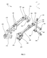
FIG. 2 illustrates, in accordance with various embodiments, a perspective view of a bogie beam sensor; -
FIG. 3 illustrates, in accordance with various embodiments, an exploded view of a bogie beam sensor; -
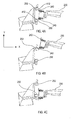
FIG. 4A illustrates, in accordance with various embodiments, a target arm in a neutral position; -
FIG. 4B illustrates, in accordance with various embodiments, a target arm in a nose up position; -
FIG. 4C illustrates, in accordance with various embodiments, a target arm in a nose down position; and -
FIG. 5 illustrates, in accordance with various embodiments, a bogie beam sensor in a maximum nose up position. - The detailed description of exemplary embodiments herein makes reference to the accompanying drawings, which show exemplary embodiments by way of illustration and their best mode. While these exemplary embodiments are described in sufficient detail to enable those skilled in the art to practice the inventions, it should be understood that other embodiments may be realized and that logical, chemical and mechanical changes may be made without departing from the scope of the inventions. Thus, the detailed description herein is presented for purposes of illustration only and not of limitation. For example, the steps recited in any of the method or process descriptions may be executed in any order and are not necessarily limited to the order presented. Furthermore, any reference to singular includes plural embodiments, and any reference to more than one component or step may include a singular embodiment or step. Also, any reference to attached, fixed, connected or the like may include permanent, removable, temporary, partial, full and/or any other possible attachment option. Additionally, any reference to without contact (or similar phrases) may also include reduced contact or minimal contact.
- Systems for detecting an angular position of a bogie beam are disclosed. A bogie-type landing gear may comprise a bogie beam. Two or more pairs of wheels may be mounted on the bogie beam. The bogie beam may be pivotably coupled to a piston of the landing gear. It may be desirable to detect small changes in the angular position of the bogie beam. A bogie beam sensor may be coupled to the bogie beam in order to detect changes in angular position of the bogie beam. The bogie beam sensor may comprise a bracket coupled to the bogie beam. A sensor may be coupled to the bracket, and a target may be coupled to a target arm which is pivotably coupled to the bracket. A drive link coupled to the piston may cause the target arm to pivot in response to the bogie beam pivoting with respect to the piston. As both the sensor and target are coupled to the bogie beam, deflections in the bogie beam or piston may not affect the relative positions of the sensor and target.
- Referring to
FIG. 1 , a portion of alanding gear 100 is illustrated according to various embodiments.Landing gear 100 may comprisecylinder 110,upper links 120,piston 130,bogie beam 140,pivot 150, andbogie beam sensor 200.Bogie beam sensor 200 may be coupled topiston 130 viapiston lug 134, andbogie beam sensor 200 may be coupled tobogie beam 140 via abogie beam lug 142. As illustrated,bogie beam sensor 200 is located aft ofpiston 130. However, in various embodimentsbogie beam sensor 200 may be located forward ofpiston 130. Forward, or fore, and aft describe spatial relationships between components, with forward referring to locations relatively closer to the front of an aircraft, and aft referring to locations relatively closer to the rear of an aircraft. -
Bogie beam 140 may rotate relative topiston 130 atpivot 150.Bogie beam sensor 200 may detect relative motion betweenpiston 130 andbogie beam 140 and may measure an angle of rotation ofbogie beam 140 relative topiston 130. Although described primarily with reference to landing gear, in various embodimentsbogie beam sensor 200 may be capable of measuring rotational movement between any type of objects. - Referring to
FIG. 2 ,bogie beam sensor 200 is illustrated according to various embodiments.Bogie beam sensor 200 may comprise sensorstroke target bracket 210,drive link 220,target arm 230, nose uptarget 240, nose downtarget 242, nose upsensor 250, nose downsensor 252, and shims 260. - Sensor
stroke target bracket 210 may comprisesensor bracket 212,bracket arm 214, andbracket elbow 216. In various embodiments,sensor bracket 212,bracket arm 214, andbracket elbow 216 may comprise a single, continuous component. However, in various embodiments,sensor bracket 212,bracket arm 214, andbracket elbow 216 may comprise separate components coupled together. Sensorstroke target bracket 210 may couplebogie beam sensor 200 tobogie beam 140 viaforward bogie lug 270 andaft bogie lug 271. In various embodiments, at least two bogie lugs 270, 271 may couplebogie beam sensor 200 tobogie beam 140. Multiple bogie lugs may prevent sensorstroke target bracket 210 from moving relative tobogie beam 140. In various embodiments, sensorstroke target bracket 210 may comprise aluminum. However, in various embodiments, sensorstroke target bracket 210 may comprise any other material, such as steel or a carbon composite or any other suitable material. -
Drive link 220 may be coupled topiston lug 272 andtarget arm 230. In response tobogie beam 140 moving relative topiston 130,drive link 220 may causetarget arm 230 to pivot in the y-direction aboutbracket elbow 216 relative tobogie 140. X, y, and z axes are shown for ease of illustration. In various embodiments,drive link 220 may comprise stainless steel. However, in various embodiments,drive link 220 may comprise aluminum, a carbon composite, or any other suitable material. -
Target arm 230 may be coupled tobracket elbow 216.Target arm 230 may also be coupled totarget bracket 280.Drive link 220 may be configured to causetarget arm 230 to pivot atbracket elbow 216. In response to targetarm 230 pivoting atbracket elbow 216,target bracket 280 may move in the y-direction relative tosensor bracket 212. In various embodiments,target arm 230 may comprise stainless steel. However, in various embodiments,target arm 230 may comprise aluminum, a carbon composite, or any other suitable material. -
Target bracket 280 may be coupled to targetarm 230, nose uptarget 240, and nose downtarget 242.Shims 260 may be located between nose uptarget 240, nose downtarget 242, andtarget bracket 280. Adjustments to the location of nose uptarget 240 and nose downtarget 242 may be made by adding or removing one ormore shims 260, or by changing the size ofshims 260. In various embodiments, nose uptarget 240 and nose downtarget 242 may be located .08 inches (.20 cm) from nose upsensor 250 and nose downsensor 252 respectively. However, in various embodiments, nose uptarget 240 and nose downtarget 242 may be located between .07 -.09 inches (.18 - .23 cm) or .04 - .16 inches (.10 - .40 cm) from nose upsensor 250 and nose downsensor 252, respectively. - Nose up
sensor 250 and nose downsensor 252 may be coupled tosensor bracket 212. In various embodiments, nose upsensor 250 and nose downsensor 252 may comprise proximity sensors. Nose upsensor 250 and nose downsensor 252 may transmit a signal to nose uptarget 240 and/or nose downtarget 242. The signals may be reflected off nose uptarget 240 and nose downtarget 242. Nose upsensor 250 and nose downsensor 252 may receive the reflected signals and detect a position of nose uptarget 240 and nose downtarget 242. Based on the reflected signals, a position ofbogie beam 140 may be determined. In various embodiments, proximity sensors such as nose upsensor 250 and nose downsensor 252 may use a variable inductance mode of operation where a change of inductance is measured. The proximity sensors may comprise an inductor which produces an electromagnetic field. As a ferromagnetic target approaches the sensor, the inductance may increase and may be detected by a versatile sensor interface module. - In various embodiments, and with momentary reference to
FIGs. 2 and3 , a distance betweenforward bogie lug 270 andaft bogie lug 271 may change slightly due to deflection frombogie beam 140 orpiston 130. Deflection may be a bending ofbogie beam 140 due to a strain, such as weight from an aircraft onlanding gear 100. In variousembodiments sensor bracket 212 may be coupled tobogie beam 140 via a sliding joint 290. Sliding joint 290 may comprise an elongated opening, or an opening with a larger radius thansensor bracket bolt 320, which may allow sensorstroke target bracket 210 to move forward and aft in the x-direction with respect tosensor bracket bolt 320. Movement ofsensor bracket bolt 320 within sliding joint 290 may prevent strain on sensorstroke target bracket 210 due to deflection ofbogie beam 140. - Referring to
FIG. 3 , a partially exploded view ofbogie beam sensor 200 is illustrated according to various embodiments. In various embodiments,bracket arm bolts 310 andsensor bracket bolt 320 may couple sensorstroke target bracket 210 tobogie beam 140. Sensorstroke target bracket 210 further comprisesbearings 330. In various embodiments,bearings 330 indrive link 220 may comprise spherical bearings. Spherical bearings may allow for slight horizontal rotation of components in the z-direction. In various embodiments,bogie beam 140 may turn in the z-direction relative topiston 130. Spherical bearings may prevent strain betweendrive link 220 andtarget arm 230, and betweentarget arm 230 andbracket elbow 216.Bogie beam sensor 200 may further compriselubrication ports 340.Lubrication ports 340 may allow lubrication, such as oil or grease, to be added to the moving components ofbogie beam sensor 200 to prevent wear on the moving components. - In various embodiments, nose up
target 240 and nose downtarget 242 may be non-parallel. Nose uptarget 240 and nose downtarget 242 may each be perpendicular tobracket elbow 216. However, due to the different location of nose uptarget 240 and nose downtarget 242 ontarget bracket 280, nose uptarget 240 and nose downtarget 242 may be non-parallel to each other. This may allow for greater sensitivity between the targets and sensors. - Referring to
FIGs. 4A-4C , various positions oftarget arm 230 are illustrated according to various embodiments. InFIG. 4A ,target arm 230 is illustrated in a neutral position. In various embodiments, the neutral position may be when an aircraft is stationary on the ground. However, in various embodiments, the neutral position may be when the aircraft is in air andlanding gear 100 is hanging in the air. In various embodiments, the neutral position may be a position in whichlanding gear 100 may be retracted into an aircraft. In the neutral position, nose uptarget 240 may be aligned with nose upsensor 250, and nose downtarget 242 may be aligned with nose downsensor 252, such that nose upsensor 250 and nose downsensor 252 each receive a signal from nose uptarget 240 and nose downtarget 242 respectively. - In various embodiments, nose up
target 240 and nose downtarget 242 may be biased with respect to nose upsensor 250 and nose downsensor 252. For example, nose uptarget 240 may be slightly offset in the y-direction with respect to nose upsensor 250. As illustrated in the neutral position inFIG. 4A , nose uptarget 240 is located above acenter point 410 of nose upsensor 250. In response to small changes in position of nose uptarget 240, the change in signal detected by nose upsensor 250 may be greater with increasing distance fromcenter point 410. Thus, in response tobogie beam 140 tilting slightly toward the nose up position, both nose uptarget 240 and nose downtarget 242 may move upward by the same distance relative to nose upsensor 250 and nose downsensor 252. However, due to the bias, nose upsensor 250 may detect a greater signal change than nose downsensor 252, because nose uptarget 240 moves away fromcenter point 410 and nose downtarget 242 moves towardcenter point 412 of nose downsensor 252. Thus, the bias may allow for more accurate measurements of small changes in a position ofbogie beam 140. - Referring to
FIG. 4B ,target arm 230 is illustrated in a nose up position. In the illustrated position, nose uptarget 240 and nose downtarget 242 may be out of range of nose upsensor 250 and nose downsensor 252. In response to the targets being out of range of the sensors, the sensors may determine that an angular position ofbogie beam 140 is greater than a maximum range ofbogie beam sensor 200. - Referring to
FIG. 4C ,target arm 230 is illustrated in a nose down position. Depending on the specifications of the targets and sensors,target arm 230 may be at a maximum range of nose upsensor 250 and nose downsensor 252. In response to targetarm 230 moving beyond the maximum range in the y-direction, nose upsensor 250 and/or nose downsensor 252 may not receive a position reading from nose uptarget 240 and/or nose downtarget 242. In various embodiments, the maximum range may equate to a change in position ofbogie beam 140 of less than or equal to +/- 1.1 degrees with respect topiston 130. However, in various embodiments, the maximum range may be between +/- .5 degrees and +/- 2 degrees, or between +/- .2 degrees and +/- 5 degrees. In various embodiments, a +/- 1.1 degree rotation ofbogie beam 140 may translate to .875 inches (2.2 cm) of relative movement between nose uptarget 240 and nose upsensor 250. - Referring to
FIG. 5 ,bogie beam sensor 200 is illustrated in a maximum nose up position. In the maximum nose up position,bogie beam 140 may be angled at a maximum nose up angle relative topiston 130. Nose uptarget 240 and nose downtarget 242 may be out of range of nose upsensor 250 and nose downsensor 252. - Benefits, other advantages, and solutions to problems have been described herein with regard to specific embodiments. Furthermore, the connecting lines shown in the various figures contained herein are intended to represent exemplary functional relationships and/or physical couplings between the various elements. It should be noted that many alternative or additional functional relationships or physical connections may be present in a practical system. However, the benefits, advantages, solutions to problems, and any elements that may cause any benefit, advantage, or solution to occur or become more pronounced are not to be construed as critical, required, or essential features or elements of the inventions. The scope of the inventions is accordingly to be limited by nothing other than the appended claims, in which reference to an element in the singular is not intended to mean "one and only one" unless explicitly so stated, but rather "one or more." Moreover, where a phrase similar to "at least one of A, B, or C" is used in the claims, it is intended that the phrase be interpreted to mean that A alone may be present in an embodiment, B alone may be present in an embodiment, C alone may be present in an embodiment, or that any combination of the elements A, B and C may be present in a single embodiment; for example, A and B, A and C, B and C, or A and B and C.
- Systems, methods and apparatus are provided herein. In the detailed description herein, references to "various embodiments", "one embodiment", "an embodiment", "an example embodiment", etc., indicate that the embodiment described may include a particular feature, structure, or characteristic, but every embodiment may not necessarily include the particular feature, structure, or characteristic. Moreover, such phrases are not necessarily referring to the same embodiment. Further, when a particular feature, structure, or characteristic is described in connection with an embodiment, it is submitted that it is within the knowledge of one skilled in the art to affect such feature, structure, or characteristic in connection with other embodiments whether or not explicitly described. After reading the description, it will be apparent to one skilled in the relevant art(s) how to implement the disclosure in alternative embodiments.
- Furthermore, no element, component, or method step in the present disclosure is intended to be dedicated to the public regardless of whether the element, component, or method step is explicitly recited in the claims. No claim element herein is to be construed under the provisions of 35 U.S.C. 112, sixth paragraph, unless the element is expressly recited using the phrase "means for." As used herein, the terms "comprises", "comprising", or any other variation thereof, are intended to cover a non-exclusive inclusion, such that a process, method, article, or apparatus that comprises a list of elements does not include only those elements but may include other elements not expressly listed or inherent to such process, method, article, or apparatus.
Claims (15)
- A bogie beam sensor (200) comprising:a bracket (210) coupled to a bogie beam (140);a sensor (250,252) coupled to the bracket (210);a target arm (230) coupled to the bracket (210);a target (240,242) coupled to the target arm (230); anda drive link (220) coupled to the target arm (230) and a piston (130).
- The bogie beam sensor of claim 1, wherein the target arm (230) is configured to pivot relative to the bracket (210).
- The bogie beam sensor of claim 1 or 2, wherein the sensor (250,252) comprises a proximity sensor.
- The bogie beam sensor of claim 1, 2 or 3, wherein the bracket (210) is coupled to the bogie beam (140) via a forward lug (270) and an aft lug (271).
- The bogie beam sensor of claim 4, wherein the aft lug (271) comprises a sliding joint.
- The bogie beam sensor of any preceding claim, wherein the drive link (220) comprises a spherical bearing (330).
- The bogie beam sensor of any preceding claim, wherein the target (240,242) comprises a nose up target (240) and a nose down target (242).
- The bogie beam sensor of claim 7, wherein the nose up target (240) and the nose down target (242) are non-parallel.
- The bogie beam sensor of any preceding claim, wherein the target (240,242) is offset relative to the sensor (250,252) in a neutral position.
- The bogie beam sensor of any preceding claim, wherein the bogie beam sensor (200) is configured to detect a change in a bogie beam position of less than or equal to +/- 1.1 degrees.
- An aircraft landing gear (100) comprising:a piston (130);a bogie beam (140) coupled to the piston (130), wherein the bogie beam (140) is configured to pivot relative to the piston (130);a target arm (230) coupled to the bogie beam (140);a sensor (250,252) coupled to the bogie beam (140); anda drive link (220) coupled to the piston (130) and the target arm (230).
- The aircraft landing gear of claim 11, wherein the drive link (220) is configured to pivot the target arm (230) with respect to the bogie beam (140) in response to the bogie beam (140) pivoting relative to the piston (130).
- The aircraft landing gear of claim 11 or 12, further comprising a target (240,242) coupled to the target arm (230).
- The aircraft landing gear of claim 11, 12 or 13, wherein the sensor (250,252) is configured to detect a rotation of the bogie beam (140) of less than or equal to 1.1 degrees.
- The aircraft landing gear of any of claims 11 to 14, wherein the drive link (220) is coupled to the target arm (230) via a spherical bearing (330).
Applications Claiming Priority (1)
| Application Number | Priority Date | Filing Date | Title |
|---|---|---|---|
| US13/963,663 US9193446B2 (en) | 2013-08-09 | 2013-08-09 | Bogie beam angle sensor |
Publications (2)
| Publication Number | Publication Date |
|---|---|
| EP2835311A1 true EP2835311A1 (en) | 2015-02-11 |
| EP2835311B1 EP2835311B1 (en) | 2016-08-03 |
Family
ID=50972533
Family Applications (1)
| Application Number | Title | Priority Date | Filing Date |
|---|---|---|---|
| EP14172833.7A Active EP2835311B1 (en) | 2013-08-09 | 2014-06-17 | Bogie beam angle sensor |
Country Status (2)
| Country | Link |
|---|---|
| US (1) | US9193446B2 (en) |
| EP (1) | EP2835311B1 (en) |
Cited By (3)
| Publication number | Priority date | Publication date | Assignee | Title |
|---|---|---|---|---|
| GB2563945A (en) * | 2017-06-30 | 2019-01-02 | Airbus Operations Ltd | Aircraft landing gear assembly |
| US11235887B2 (en) | 2017-06-30 | 2022-02-01 | Airbus Operations Limited | Aircraft landing gear assembly |
| WO2022170420A1 (en) * | 2021-02-09 | 2022-08-18 | Safran Landing Systems Canada Inc. | Hybrid main landing gear fitting with detachable drag arm |
Families Citing this family (6)
| Publication number | Priority date | Publication date | Assignee | Title |
|---|---|---|---|---|
| EP3336485B1 (en) | 2016-12-15 | 2020-09-23 | Safran Landing Systems UK Limited | Aircraft assembly including deflection sensor |
| US10577128B2 (en) * | 2018-03-30 | 2020-03-03 | The Boeing Company | Health monitoring of aircraft landing gear mechanical structures |
| GB2581825A (en) * | 2019-02-28 | 2020-09-02 | Airbus Operations Ltd | Landing gear retraction |
| GB2605160B (en) * | 2021-03-24 | 2023-05-31 | Safran Landing Systems Uk Ltd | Aircraft landing gear torque link assembly |
| CN113562167B (en) * | 2021-08-07 | 2024-06-18 | 中国航空工业集团公司沈阳飞机设计研究所 | Multi-position monitoring device for retraction of undercarriage |
| CN115056973A (en) * | 2022-05-27 | 2022-09-16 | 中国航空工业集团公司沈阳飞机设计研究所 | Undercarriage compression switch special mechanism adaptive to proximity switch |
Citations (3)
| Publication number | Priority date | Publication date | Assignee | Title |
|---|---|---|---|---|
| US20070023012A1 (en) * | 2005-07-26 | 2007-02-01 | Toyota Jidosha Kabushiki Kaisha | Controller for direct-injection internal combustion engine and method of controlling the direct-injection internal combustion engine |
| EP2489591A1 (en) * | 2011-02-21 | 2012-08-22 | The Boeing Company | Air-ground detection system for semi-levered landing gear |
| GB2489058A (en) * | 2011-08-22 | 2012-09-19 | Messier Dowty Ltd | Aircraft landing gear |
Family Cites Families (7)
| Publication number | Priority date | Publication date | Assignee | Title |
|---|---|---|---|---|
| US2851231A (en) * | 1956-08-23 | 1958-09-09 | Cleveland Pneumatic Ind Inc | Landing gear assembly |
| DE4112674A1 (en) * | 1990-09-13 | 1992-03-19 | Vdo Schindling | ARRANGEMENT OF SENSORS ON THE UNDERCARRIAGE OF AN AIRCRAFT FOR MEASURING THE WEIGHT AND FOCUS OF THE AIRCRAFT |
| US7274309B2 (en) * | 2005-03-29 | 2007-09-25 | Nance C Kirk | Aircraft landing gear initial touch-down velocity monitor |
| GB0517351D0 (en) * | 2005-08-24 | 2005-10-05 | Airbus Uk Ltd | Landing load monitor for aircraft landing gear |
| US8079548B2 (en) * | 2009-04-02 | 2011-12-20 | Goodrich Corporation | Ground sensing system |
| GB2480623A (en) * | 2010-05-25 | 2011-11-30 | Messier Dowty Ltd | Steerable landing gear with locking mechanism |
| US8933713B2 (en) * | 2010-07-19 | 2015-01-13 | Goodrich Corporation | Capacitive sensors for monitoring loads |
-
2013
- 2013-08-09 US US13/963,663 patent/US9193446B2/en active Active
-
2014
- 2014-06-17 EP EP14172833.7A patent/EP2835311B1/en active Active
Patent Citations (3)
| Publication number | Priority date | Publication date | Assignee | Title |
|---|---|---|---|---|
| US20070023012A1 (en) * | 2005-07-26 | 2007-02-01 | Toyota Jidosha Kabushiki Kaisha | Controller for direct-injection internal combustion engine and method of controlling the direct-injection internal combustion engine |
| EP2489591A1 (en) * | 2011-02-21 | 2012-08-22 | The Boeing Company | Air-ground detection system for semi-levered landing gear |
| GB2489058A (en) * | 2011-08-22 | 2012-09-19 | Messier Dowty Ltd | Aircraft landing gear |
Cited By (4)
| Publication number | Priority date | Publication date | Assignee | Title |
|---|---|---|---|---|
| GB2563945A (en) * | 2017-06-30 | 2019-01-02 | Airbus Operations Ltd | Aircraft landing gear assembly |
| US11235887B2 (en) | 2017-06-30 | 2022-02-01 | Airbus Operations Limited | Aircraft landing gear assembly |
| WO2022170420A1 (en) * | 2021-02-09 | 2022-08-18 | Safran Landing Systems Canada Inc. | Hybrid main landing gear fitting with detachable drag arm |
| US11708150B2 (en) | 2021-02-09 | 2023-07-25 | Safran Landing Systems Canada Inc. | Hybrid main landing gear fitting with detachable drag arm |
Also Published As
| Publication number | Publication date |
|---|---|
| US20150041585A1 (en) | 2015-02-12 |
| US9193446B2 (en) | 2015-11-24 |
| EP2835311B1 (en) | 2016-08-03 |
Similar Documents
| Publication | Publication Date | Title |
|---|---|---|
| EP2835311B1 (en) | Bogie beam angle sensor | |
| CN103577697B (en) | FOD detection method based on road surface point cloud data | |
| US7774949B2 (en) | Coordinate measurement machine | |
| CN109794964B (en) | Static compliance performance testing device applied to industrial robot | |
| US8966998B2 (en) | Support unit | |
| US7743524B2 (en) | Coordinate measurement machine with improved joint | |
| US7864342B2 (en) | Apparatus and method for measuring displacement of a curved surface using dual laser beams | |
| CN112665879B (en) | A target surface deviation measurement and adjustment method and device for a wheel posture measurement system | |
| CN109466795B (en) | Automatic test platform of unmanned helicopter | |
| EP2738133B1 (en) | Lifter for handling a rotor blade of a wind turbine and method of operating the same | |
| EP2530019A1 (en) | Resolver type skew sensor with gimbal attachment | |
| CN108951386A (en) | A kind of surface evenness detection device | |
| CN111811428A (en) | Measuring systems for rail vehicle limits | |
| CN102829825B (en) | Flight parameter measurement system for small-size bypass aircraft | |
| US9910058B2 (en) | Method and device for measuring the angle of attack and the sideslip of an aircraft | |
| US11235887B2 (en) | Aircraft landing gear assembly | |
| CN109100066B (en) | Intelligent assembly collision detection device | |
| CN102249153B (en) | Device for detecting rotating angle, control method thereof and crane comprising same | |
| CN108820250B (en) | Undercarriage open ground state detection device | |
| CN112173997B (en) | Intelligent folding arm crane safety early warning and control method based on cloud side end data fusion | |
| CN217739465U (en) | Ground penetrating radar detection device | |
| CN109387176A (en) | A kind of aircraft rudder surface angle displacement measuring device | |
| KR100946639B1 (en) | A flap/lag angle measurement system and measurement method for helicopter rotor blade | |
| KR20190051905A (en) | Angle measuring apparatus having multi-link | |
| JP5118667B2 (en) | Wheel position measuring device |
Legal Events
| Date | Code | Title | Description |
|---|---|---|---|
| PUAI | Public reference made under article 153(3) epc to a published international application that has entered the european phase |
Free format text: ORIGINAL CODE: 0009012 |
|
| 17P | Request for examination filed |
Effective date: 20140617 |
|
| AK | Designated contracting states |
Kind code of ref document: A1 Designated state(s): AL AT BE BG CH CY CZ DE DK EE ES FI FR GB GR HR HU IE IS IT LI LT LU LV MC MK MT NL NO PL PT RO RS SE SI SK SM TR |
|
| AX | Request for extension of the european patent |
Extension state: BA ME |
|
| R17P | Request for examination filed (corrected) |
Effective date: 20150810 |
|
| RBV | Designated contracting states (corrected) |
Designated state(s): AL AT BE BG CH CY CZ DE DK EE ES FI FR GB GR HR HU IE IS IT LI LT LU LV MC MK MT NL NO PL PT RO RS SE SI SK SM TR |
|
| GRAP | Despatch of communication of intention to grant a patent |
Free format text: ORIGINAL CODE: EPIDOSNIGR1 |
|
| INTG | Intention to grant announced |
Effective date: 20160205 |
|
| GRAS | Grant fee paid |
Free format text: ORIGINAL CODE: EPIDOSNIGR3 |
|
| GRAA | (expected) grant |
Free format text: ORIGINAL CODE: 0009210 |
|
| AK | Designated contracting states |
Kind code of ref document: B1 Designated state(s): AL AT BE BG CH CY CZ DE DK EE ES FI FR GB GR HR HU IE IS IT LI LT LU LV MC MK MT NL NO PL PT RO RS SE SI SK SM TR |
|
| REG | Reference to a national code |
Ref country code: GB Ref legal event code: FG4D |
|
| REG | Reference to a national code |
Ref country code: CH Ref legal event code: EP Ref country code: AT Ref legal event code: REF Ref document number: 817148 Country of ref document: AT Kind code of ref document: T Effective date: 20160815 |
|
| REG | Reference to a national code |
Ref country code: IE Ref legal event code: FG4D |
|
| REG | Reference to a national code |
Ref country code: DE Ref legal event code: R096 Ref document number: 602014002955 Country of ref document: DE |
|
| REG | Reference to a national code |
Ref country code: NL Ref legal event code: MP Effective date: 20160803 |
|
| REG | Reference to a national code |
Ref country code: LT Ref legal event code: MG4D |
|
| REG | Reference to a national code |
Ref country code: AT Ref legal event code: MK05 Ref document number: 817148 Country of ref document: AT Kind code of ref document: T Effective date: 20160803 |
|
| PG25 | Lapsed in a contracting state [announced via postgrant information from national office to epo] |
Ref country code: FI Free format text: LAPSE BECAUSE OF FAILURE TO SUBMIT A TRANSLATION OF THE DESCRIPTION OR TO PAY THE FEE WITHIN THE PRESCRIBED TIME-LIMIT Effective date: 20160803 Ref country code: HR Free format text: LAPSE BECAUSE OF FAILURE TO SUBMIT A TRANSLATION OF THE DESCRIPTION OR TO PAY THE FEE WITHIN THE PRESCRIBED TIME-LIMIT Effective date: 20160803 Ref country code: NO Free format text: LAPSE BECAUSE OF FAILURE TO SUBMIT A TRANSLATION OF THE DESCRIPTION OR TO PAY THE FEE WITHIN THE PRESCRIBED TIME-LIMIT Effective date: 20161103 Ref country code: LT Free format text: LAPSE BECAUSE OF FAILURE TO SUBMIT A TRANSLATION OF THE DESCRIPTION OR TO PAY THE FEE WITHIN THE PRESCRIBED TIME-LIMIT Effective date: 20160803 Ref country code: IT Free format text: LAPSE BECAUSE OF FAILURE TO SUBMIT A TRANSLATION OF THE DESCRIPTION OR TO PAY THE FEE WITHIN THE PRESCRIBED TIME-LIMIT Effective date: 20160803 Ref country code: NL Free format text: LAPSE BECAUSE OF FAILURE TO SUBMIT A TRANSLATION OF THE DESCRIPTION OR TO PAY THE FEE WITHIN THE PRESCRIBED TIME-LIMIT Effective date: 20160803 Ref country code: RS Free format text: LAPSE BECAUSE OF FAILURE TO SUBMIT A TRANSLATION OF THE DESCRIPTION OR TO PAY THE FEE WITHIN THE PRESCRIBED TIME-LIMIT Effective date: 20160803 Ref country code: IS Free format text: LAPSE BECAUSE OF FAILURE TO SUBMIT A TRANSLATION OF THE DESCRIPTION OR TO PAY THE FEE WITHIN THE PRESCRIBED TIME-LIMIT Effective date: 20161203 |
|
| PG25 | Lapsed in a contracting state [announced via postgrant information from national office to epo] |
Ref country code: AT Free format text: LAPSE BECAUSE OF FAILURE TO SUBMIT A TRANSLATION OF THE DESCRIPTION OR TO PAY THE FEE WITHIN THE PRESCRIBED TIME-LIMIT Effective date: 20160803 Ref country code: SE Free format text: LAPSE BECAUSE OF FAILURE TO SUBMIT A TRANSLATION OF THE DESCRIPTION OR TO PAY THE FEE WITHIN THE PRESCRIBED TIME-LIMIT Effective date: 20160803 Ref country code: PT Free format text: LAPSE BECAUSE OF FAILURE TO SUBMIT A TRANSLATION OF THE DESCRIPTION OR TO PAY THE FEE WITHIN THE PRESCRIBED TIME-LIMIT Effective date: 20161205 Ref country code: GR Free format text: LAPSE BECAUSE OF FAILURE TO SUBMIT A TRANSLATION OF THE DESCRIPTION OR TO PAY THE FEE WITHIN THE PRESCRIBED TIME-LIMIT Effective date: 20161104 Ref country code: PL Free format text: LAPSE BECAUSE OF FAILURE TO SUBMIT A TRANSLATION OF THE DESCRIPTION OR TO PAY THE FEE WITHIN THE PRESCRIBED TIME-LIMIT Effective date: 20160803 Ref country code: LV Free format text: LAPSE BECAUSE OF FAILURE TO SUBMIT A TRANSLATION OF THE DESCRIPTION OR TO PAY THE FEE WITHIN THE PRESCRIBED TIME-LIMIT Effective date: 20160803 Ref country code: ES Free format text: LAPSE BECAUSE OF FAILURE TO SUBMIT A TRANSLATION OF THE DESCRIPTION OR TO PAY THE FEE WITHIN THE PRESCRIBED TIME-LIMIT Effective date: 20160803 |
|
| PG25 | Lapsed in a contracting state [announced via postgrant information from national office to epo] |
Ref country code: RO Free format text: LAPSE BECAUSE OF FAILURE TO SUBMIT A TRANSLATION OF THE DESCRIPTION OR TO PAY THE FEE WITHIN THE PRESCRIBED TIME-LIMIT Effective date: 20160803 Ref country code: EE Free format text: LAPSE BECAUSE OF FAILURE TO SUBMIT A TRANSLATION OF THE DESCRIPTION OR TO PAY THE FEE WITHIN THE PRESCRIBED TIME-LIMIT Effective date: 20160803 |
|
| REG | Reference to a national code |
Ref country code: DE Ref legal event code: R097 Ref document number: 602014002955 Country of ref document: DE |
|
| REG | Reference to a national code |
Ref country code: FR Ref legal event code: PLFP Year of fee payment: 4 |
|
| PG25 | Lapsed in a contracting state [announced via postgrant information from national office to epo] |
Ref country code: SM Free format text: LAPSE BECAUSE OF FAILURE TO SUBMIT A TRANSLATION OF THE DESCRIPTION OR TO PAY THE FEE WITHIN THE PRESCRIBED TIME-LIMIT Effective date: 20160803 Ref country code: SK Free format text: LAPSE BECAUSE OF FAILURE TO SUBMIT A TRANSLATION OF THE DESCRIPTION OR TO PAY THE FEE WITHIN THE PRESCRIBED TIME-LIMIT Effective date: 20160803 Ref country code: BG Free format text: LAPSE BECAUSE OF FAILURE TO SUBMIT A TRANSLATION OF THE DESCRIPTION OR TO PAY THE FEE WITHIN THE PRESCRIBED TIME-LIMIT Effective date: 20161103 Ref country code: BE Free format text: LAPSE BECAUSE OF FAILURE TO SUBMIT A TRANSLATION OF THE DESCRIPTION OR TO PAY THE FEE WITHIN THE PRESCRIBED TIME-LIMIT Effective date: 20160803 Ref country code: DK Free format text: LAPSE BECAUSE OF FAILURE TO SUBMIT A TRANSLATION OF THE DESCRIPTION OR TO PAY THE FEE WITHIN THE PRESCRIBED TIME-LIMIT Effective date: 20160803 Ref country code: CZ Free format text: LAPSE BECAUSE OF FAILURE TO SUBMIT A TRANSLATION OF THE DESCRIPTION OR TO PAY THE FEE WITHIN THE PRESCRIBED TIME-LIMIT Effective date: 20160803 |
|
| PLBE | No opposition filed within time limit |
Free format text: ORIGINAL CODE: 0009261 |
|
| STAA | Information on the status of an ep patent application or granted ep patent |
Free format text: STATUS: NO OPPOSITION FILED WITHIN TIME LIMIT |
|
| 26N | No opposition filed |
Effective date: 20170504 |
|
| PG25 | Lapsed in a contracting state [announced via postgrant information from national office to epo] |
Ref country code: SI Free format text: LAPSE BECAUSE OF FAILURE TO SUBMIT A TRANSLATION OF THE DESCRIPTION OR TO PAY THE FEE WITHIN THE PRESCRIBED TIME-LIMIT Effective date: 20160803 |
|
| PG25 | Lapsed in a contracting state [announced via postgrant information from national office to epo] |
Ref country code: MC Free format text: LAPSE BECAUSE OF FAILURE TO SUBMIT A TRANSLATION OF THE DESCRIPTION OR TO PAY THE FEE WITHIN THE PRESCRIBED TIME-LIMIT Effective date: 20160803 |
|
| REG | Reference to a national code |
Ref country code: CH Ref legal event code: PL |
|
| REG | Reference to a national code |
Ref country code: IE Ref legal event code: MM4A |
|
| PG25 | Lapsed in a contracting state [announced via postgrant information from national office to epo] |
Ref country code: LU Free format text: LAPSE BECAUSE OF NON-PAYMENT OF DUE FEES Effective date: 20170617 Ref country code: IE Free format text: LAPSE BECAUSE OF NON-PAYMENT OF DUE FEES Effective date: 20170617 Ref country code: CH Free format text: LAPSE BECAUSE OF NON-PAYMENT OF DUE FEES Effective date: 20170630 Ref country code: LI Free format text: LAPSE BECAUSE OF NON-PAYMENT OF DUE FEES Effective date: 20170630 |
|
| REG | Reference to a national code |
Ref country code: FR Ref legal event code: PLFP Year of fee payment: 5 |
|
| PG25 | Lapsed in a contracting state [announced via postgrant information from national office to epo] |
Ref country code: MT Free format text: LAPSE BECAUSE OF NON-PAYMENT OF DUE FEES Effective date: 20170617 |
|
| PG25 | Lapsed in a contracting state [announced via postgrant information from national office to epo] |
Ref country code: AL Free format text: LAPSE BECAUSE OF FAILURE TO SUBMIT A TRANSLATION OF THE DESCRIPTION OR TO PAY THE FEE WITHIN THE PRESCRIBED TIME-LIMIT Effective date: 20160803 |
|
| GBPC | Gb: european patent ceased through non-payment of renewal fee |
Effective date: 20180617 |
|
| PG25 | Lapsed in a contracting state [announced via postgrant information from national office to epo] |
Ref country code: GB Free format text: LAPSE BECAUSE OF NON-PAYMENT OF DUE FEES Effective date: 20180617 |
|
| PG25 | Lapsed in a contracting state [announced via postgrant information from national office to epo] |
Ref country code: HU Free format text: LAPSE BECAUSE OF FAILURE TO SUBMIT A TRANSLATION OF THE DESCRIPTION OR TO PAY THE FEE WITHIN THE PRESCRIBED TIME-LIMIT; INVALID AB INITIO Effective date: 20140617 |
|
| PG25 | Lapsed in a contracting state [announced via postgrant information from national office to epo] |
Ref country code: CY Free format text: LAPSE BECAUSE OF FAILURE TO SUBMIT A TRANSLATION OF THE DESCRIPTION OR TO PAY THE FEE WITHIN THE PRESCRIBED TIME-LIMIT Effective date: 20160803 |
|
| PG25 | Lapsed in a contracting state [announced via postgrant information from national office to epo] |
Ref country code: MK Free format text: LAPSE BECAUSE OF FAILURE TO SUBMIT A TRANSLATION OF THE DESCRIPTION OR TO PAY THE FEE WITHIN THE PRESCRIBED TIME-LIMIT Effective date: 20160803 |
|
| PG25 | Lapsed in a contracting state [announced via postgrant information from national office to epo] |
Ref country code: TR Free format text: LAPSE BECAUSE OF FAILURE TO SUBMIT A TRANSLATION OF THE DESCRIPTION OR TO PAY THE FEE WITHIN THE PRESCRIBED TIME-LIMIT Effective date: 20160803 |
|
| REG | Reference to a national code |
Ref country code: DE Ref legal event code: R082 Ref document number: 602014002955 Country of ref document: DE |
|
| P01 | Opt-out of the competence of the unified patent court (upc) registered |
Effective date: 20230522 |
|
| PGFP | Annual fee paid to national office [announced via postgrant information from national office to epo] |
Ref country code: DE Payment date: 20250520 Year of fee payment: 12 |
|
| PGFP | Annual fee paid to national office [announced via postgrant information from national office to epo] |
Ref country code: FR Payment date: 20250520 Year of fee payment: 12 |