EP2835104B1 - Applicator for surgical clips - Google Patents
Applicator for surgical clips Download PDFInfo
- Publication number
- EP2835104B1 EP2835104B1 EP14189734.8A EP14189734A EP2835104B1 EP 2835104 B1 EP2835104 B1 EP 2835104B1 EP 14189734 A EP14189734 A EP 14189734A EP 2835104 B1 EP2835104 B1 EP 2835104B1
- Authority
- EP
- European Patent Office
- Prior art keywords
- crimping
- pusher
- applicator
- barrel
- lever
- Prior art date
- Legal status (The legal status is an assumption and is not a legal conclusion. Google has not performed a legal analysis and makes no representation as to the accuracy of the status listed.)
- Active
Links
Images



Classifications
-
- A—HUMAN NECESSITIES
- A61—MEDICAL OR VETERINARY SCIENCE; HYGIENE
- A61B—DIAGNOSIS; SURGERY; IDENTIFICATION
- A61B17/00—Surgical instruments, devices or methods
- A61B17/12—Surgical instruments, devices or methods for ligaturing or otherwise compressing tubular parts of the body, e.g. blood vessels or umbilical cord
- A61B17/128—Surgical instruments, devices or methods for ligaturing or otherwise compressing tubular parts of the body, e.g. blood vessels or umbilical cord for applying or removing clamps or clips
- A61B17/1285—Surgical instruments, devices or methods for ligaturing or otherwise compressing tubular parts of the body, e.g. blood vessels or umbilical cord for applying or removing clamps or clips for minimally invasive surgery
-
- A—HUMAN NECESSITIES
- A61—MEDICAL OR VETERINARY SCIENCE; HYGIENE
- A61B—DIAGNOSIS; SURGERY; IDENTIFICATION
- A61B17/00—Surgical instruments, devices or methods
- A61B17/00234—Surgical instruments, devices or methods for minimally invasive surgery
-
- A—HUMAN NECESSITIES
- A61—MEDICAL OR VETERINARY SCIENCE; HYGIENE
- A61B—DIAGNOSIS; SURGERY; IDENTIFICATION
- A61B17/00—Surgical instruments, devices or methods
- A61B17/068—Surgical staplers, e.g. containing multiple staples or clamps
-
- A—HUMAN NECESSITIES
- A61—MEDICAL OR VETERINARY SCIENCE; HYGIENE
- A61B—DIAGNOSIS; SURGERY; IDENTIFICATION
- A61B17/00—Surgical instruments, devices or methods
- A61B17/10—Surgical instruments, devices or methods for applying or removing wound clamps, e.g. containing only one clamp or staple; Wound clamp magazines
-
- A—HUMAN NECESSITIES
- A61—MEDICAL OR VETERINARY SCIENCE; HYGIENE
- A61B—DIAGNOSIS; SURGERY; IDENTIFICATION
- A61B17/00—Surgical instruments, devices or methods
- A61B17/12—Surgical instruments, devices or methods for ligaturing or otherwise compressing tubular parts of the body, e.g. blood vessels or umbilical cord
- A61B17/128—Surgical instruments, devices or methods for ligaturing or otherwise compressing tubular parts of the body, e.g. blood vessels or umbilical cord for applying or removing clamps or clips
-
- A—HUMAN NECESSITIES
- A61—MEDICAL OR VETERINARY SCIENCE; HYGIENE
- A61B—DIAGNOSIS; SURGERY; IDENTIFICATION
- A61B17/00—Surgical instruments, devices or methods
- A61B2017/0042—Surgical instruments, devices or methods with special provisions for gripping
- A61B2017/00424—Surgical instruments, devices or methods with special provisions for gripping ergonomic, e.g. fitting in fist
-
- A—HUMAN NECESSITIES
- A61—MEDICAL OR VETERINARY SCIENCE; HYGIENE
- A61B—DIAGNOSIS; SURGERY; IDENTIFICATION
- A61B17/00—Surgical instruments, devices or methods
- A61B2017/0042—Surgical instruments, devices or methods with special provisions for gripping
- A61B2017/00438—Surgical instruments, devices or methods with special provisions for gripping connectable to a finger
-
- A—HUMAN NECESSITIES
- A61—MEDICAL OR VETERINARY SCIENCE; HYGIENE
- A61B—DIAGNOSIS; SURGERY; IDENTIFICATION
- A61B17/00—Surgical instruments, devices or methods
- A61B17/0057—Implements for plugging an opening in the wall of a hollow or tubular organ, e.g. for sealing a vessel puncture or closing a cardiac septal defect
- A61B2017/00575—Implements for plugging an opening in the wall of a hollow or tubular organ, e.g. for sealing a vessel puncture or closing a cardiac septal defect for closure at remote site, e.g. closing atrial septum defects
- A61B2017/00584—Clips
-
- A—HUMAN NECESSITIES
- A61—MEDICAL OR VETERINARY SCIENCE; HYGIENE
- A61B—DIAGNOSIS; SURGERY; IDENTIFICATION
- A61B17/00—Surgical instruments, devices or methods
- A61B2017/00681—Aspects not otherwise provided for
- A61B2017/00725—Calibration or performance testing
-
- A—HUMAN NECESSITIES
- A61—MEDICAL OR VETERINARY SCIENCE; HYGIENE
- A61B—DIAGNOSIS; SURGERY; IDENTIFICATION
- A61B17/00—Surgical instruments, devices or methods
- A61B17/04—Surgical instruments, devices or methods for suturing wounds; Holders or packages for needles or suture materials
- A61B17/0487—Suture clamps, clips or locks, e.g. for replacing suture knots; Instruments for applying or removing suture clamps, clips or locks
- A61B2017/0488—Instruments for applying suture clamps, clips or locks
-
- A—HUMAN NECESSITIES
- A61—MEDICAL OR VETERINARY SCIENCE; HYGIENE
- A61B—DIAGNOSIS; SURGERY; IDENTIFICATION
- A61B17/00—Surgical instruments, devices or methods
- A61B17/28—Surgical forceps
- A61B17/29—Forceps for use in minimally invasive surgery
- A61B17/2909—Handles
- A61B2017/2912—Handles transmission of forces to actuating rod or piston
- A61B2017/2919—Handles transmission of forces to actuating rod or piston details of linkages or pivot points
-
- A—HUMAN NECESSITIES
- A61—MEDICAL OR VETERINARY SCIENCE; HYGIENE
- A61B—DIAGNOSIS; SURGERY; IDENTIFICATION
- A61B17/00—Surgical instruments, devices or methods
- A61B17/28—Surgical forceps
- A61B17/29—Forceps for use in minimally invasive surgery
- A61B17/2909—Handles
- A61B2017/2925—Pistol grips
-
- A—HUMAN NECESSITIES
- A61—MEDICAL OR VETERINARY SCIENCE; HYGIENE
- A61B—DIAGNOSIS; SURGERY; IDENTIFICATION
- A61B17/00—Surgical instruments, devices or methods
- A61B17/28—Surgical forceps
- A61B17/29—Forceps for use in minimally invasive surgery
- A61B2017/2926—Details of heads or jaws
- A61B2017/2932—Transmission of forces to jaw members
- A61B2017/2933—Transmission of forces to jaw members camming or guiding means
- A61B2017/2936—Pins in guiding slots
-
- A—HUMAN NECESSITIES
- A61—MEDICAL OR VETERINARY SCIENCE; HYGIENE
- A61B—DIAGNOSIS; SURGERY; IDENTIFICATION
- A61B90/00—Instruments, implements or accessories specially adapted for surgery or diagnosis and not covered by any of the groups A61B1/00 - A61B50/00, e.g. for luxation treatment or for protecting wound edges
- A61B90/08—Accessories or related features not otherwise provided for
- A61B2090/0807—Indication means
- A61B2090/0811—Indication means for the position of a particular part of an instrument with respect to the rest of the instrument, e.g. position of the anvil of a stapling instrument
-
- A—HUMAN NECESSITIES
- A61—MEDICAL OR VETERINARY SCIENCE; HYGIENE
- A61B—DIAGNOSIS; SURGERY; IDENTIFICATION
- A61B90/00—Instruments, implements or accessories specially adapted for surgery or diagnosis and not covered by any of the groups A61B1/00 - A61B50/00, e.g. for luxation treatment or for protecting wound edges
- A61B90/08—Accessories or related features not otherwise provided for
- A61B2090/0814—Preventing re-use
Definitions
- This application relates to applicators for surgical clips, and more particularly to applicators for the insertion and closure of surgical clips.
- Such applicators are intended for single handed operation by an operating surgeon. Examples of such applicators are described in international patent application publication numbers WO 2005/039422 and WO-A-01/12079 .
- Such clips may be used for sterilisation or other medical, orthopaedic or surgical purposes.
- An example is the "Filshie” clip which is disclosed in GB patent number 2177748 .
- Certain known applicators for such clips use a pushrod and associated linkage mechanism to cause rotation of an articulated jaw to produce compression forces on a clip and to thereby compress the clip causing it to close, preferably with a latching action.
- the compression forces on the relatively slender pushrod cause radial reaction forces and consequent friction at the interface between the pushrod and the outer tube. This can result in the applicator mechanism sticking in the closed position thus causing problems for the operating surgeon in disengaging the applicator from the closed clip.
- Such an applicator has a rod which consists of upper and lower rods wherein the upper rod is slidable relative to the lower rod so as to close opposing jaws at one end of the rod.
- a further example of a known applicator is described in US 3954108A .
- a problem with known applicators is the need to adjust the travel of the mechanism in order to achieve correct closure of the clip to an accurate position; such adjustment can be costly to achieve. It is important that the surgical clip is closed to an accurate position. If the clip is closed too tightly, the tubular anatomy may be severed, requiring the surgeon to apply further clips to severed ends of the tubular anatomy. Conversely, if applied clips are not closed sufficiently tightly, the tubular anatomy may not be properly occluded.
- a further problem with known applicators is the requirement that the applicator must be made from expensive components in order to ensure that the surgical clips can be closed accurately, and to be able to perform many clip closure operations.
- mechanical forces e.g. the force of the surgeon pulling the trigger, which is converted to a closing force on the clip
- tolerances are carefully monitored and, if need be, adjusted in the manufacturing environment. This can be expensive, and increases the manufacturing cost of the applicator.
- Another object of the invention is to provide an applicator which can precisely close and secure surgical clips to an accurate position.
- a further object of the invention is to provide an applicator which may be more precisely manipulated than known applicators, whilst also being operable to close and secure accurately a surgical clip.
- a still further object of the invention is to provide an applicator for surgical clips which is of a simpler and more robust design to such known applicators.
- Yet another object of the invention is to provide an applicator for surgical clips which is easier and cheaper to manufacture than existing applicators
- Such an applicator may be partially or completely disposable.
- a hand-operable surgical clip applicator comprising a barrel having a first end and a second end, the second end formed as a first crimping surface and being able to accommodate a surgical clip; a crimping lever, the crimping lever pivotally connected to the barrel, the crimping lever having a second crimping surface and an opening peg integrally formed therewith, the second crimping surface being in opposition to the first crimping surface, the first crimping surface and the second crimping surface being biased away from one another; and a pushrod, which may abut, and in use does abut, the crimping lever and constrains the opening peg, the pushrod being slidably located within the barrel; wherein the hand-operable surgical clip applicator is configured such that movement of the pushrod towards the second end of the barrel causes the pushrod to push the crimping lever, further causing the second crimping surface to close onto the first crimping surface and being able to accommodate
- linear movement of the pushrod towards the second end of the barrel results in the second end of the pushrod pushing against the crimping lever.
- This causes a rotational movement of the crimping lever.
- the second end of the pushrod acts to pull on the opening peg of the crimping lever to thereby cause the crimping lever to move such that the crimping surfaces are in an open position.
- the pusher experiences no bending forces which may cause it to bind in the barrel.
- the pushrod includes a hollow portion, with a return spring being accommodated within the hollow portion.
- Locating the return spring within the pushrod ensures that the surgical clip will be released from the applicator in the event that any part of the handle, trigger or actuating means should fail in use, thereby improving reliability of the applicator.
- the barrel is formed from a single piece of material.
- Forming the barrel from a single piece of material reduces the number of component parts in the applicator, making it easier to assemble and lowering the manufacturing costs.
- the pusher is formed with sliding surface at each of the first and second ends, the sliding surfaces configured to slide within the internal surface of the barrel, the portion of the pusher between the first and second ends having a smaller diameter than each of the first and second ends.
- Such a pusher has a waisted profile which facilitates insertion of the pusher into the barrel during assembly of the applicator.
- the waisted feature also reduces the friction between the pusher and the barrel during operation of the applicator.
- the stroke of the pushrod is limited by the stop face of the pusher abutting the crimping lever.
- the stop face of the pusher abutting the crimping lever provides a first end stop to the travel of the trigger and the consequent rotation of the crimping lever. This prevents the crimping lever from closing the surgical clip past the nominal closed position. Such "over-closing" can result in the clip being closed too tightly.
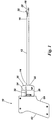
- Figure 1 shows a hand-operable surgical clip applicator according to the invention.
- the applicator 10 comprises a barrel 12, a trigger 28 and a handle 62.
- the barrel 12 has a first end 14 and a second end 16.
- the second end of the barrel 16 is formed as a first crimping surface 18 and accommodates a surgical clip.
- the barrel 12 is formed from a single piece of stainless steel tubing.
- a crimping lever 20 is pivotally mounted at the second end of the barrel 16.
- the crimping lever 20 has a second crimping surface 22 and an opening peg 24 formed integrally.
- the second crimping surface 22 of the crimping lever 20 and the first crimping surface 18 at the second end of the barrel 16 act as a co-operative pair of jaws to crimp the surgical clip and to urge the clip from an open position to a closed position.
- a pushrod assembly 42 is slidably located within the barrel 12 and comprises a transfer rod 44 and a pusher 50.
- the transfer rod 44 has a first end 46 and a second end 48.
- the pusher 50 has a first end 52 and a second end 54.
- the second end 54 of the pusher 50 is formed with a slot 53 which constrains the opening peg 24 of the crimping lever 20 and a stop face 55.
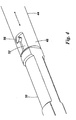
- the first end 52 of the pusher 50 is operatively coupled to the second end 48 of the transfer rod 44 by a bayonet coupling 56, as shown in Figure 4 .
- the pusher 50 is waisted and is formed with sliding surfaces at each of the first and second ends 52, 54 which slide along the internal surface of the barrel 12.
- This waisted feature facilitates assembly of the pusher 50 into the barrel; the waisted feature also reduces the friction between the pusher 50 and the barrel 12, compared to if the whole of the pusher 50 had a consistent radius along its length.
- the trigger 28 is co-located with the barrel 12 and includes a pressing surface 30 on each of two opposing sides of the barrel 12.
- Each of the pressing surfaces 30 is sized to be operable by the first and second fingers of the surgeon's hand respectively.
- the trigger is preferably moulded from a thermoplastic material.
- the trigger 28 includes a visual indicator 32 in each side of the trigger 28.
- the visual indicator 32 takes the form of a slot in each side of the trigger 28 with a reference mark 34 moulded into the side surface of the trigger 28.
- the visual indicator 32 provides a visual indication of an intermediate or "half closed” trigger position.
- the trigger 28 is depressed such that the reference mark 34 is aligned with a locating plate 110, the trigger 28 is "half closed”. This can be important as it allows the surgeon to operate the applicator 10 to hold and partially close the surgical clip without latching the clip, thus enabling the applicator and the clip to be inserted through the cannula prior to being positioned, closed and secured.
- the trigger 28 further includes an actuating slot 36 on each side of the trigger which is part of a lever mechanism.
- the handle 62 is formed in two parts.
- the handle 62 is preferably moulded from a thermoplastic material.
- the handle 62 includes a first lever 72 and a second lever 88.
- the first lever 72 has a first end 74 and a second end 76.
- the second lever 88 has a first end 90, a second end 92 and a centre region 94.
- the first end 74 of the first lever 72 is pivotally connected to the handle 62 by a first pivot 80.
- the second end 76 of the first lever 72 is slidably connected to the trigger 28.
- Two actuating pegs 82 formed on opposing sides of the second end 76 of the first lever 72 engage with the actuating slot 36 of the trigger 28.
- the first lever 72 is formed with a U-shaped cross-section.
- the first lever 72 is preferably moulded from a thermoplastic material.
- the centre region 94 of the second lever 88 is pivotally connected to the handle 62 by a second pivot pin 96.
- the first end 90 of the second lever 88 is arranged to slide along the length of the first lever 72 with the first end 90 of the second lever 88 located within the U-shaped profile of the first lever 72.
- the second end 92 of the second lever 88 presses against the first end of the transfer rod 46.
- the second lever 88 is preferably formed from stainless steel.
- the first lever 72 and the second lever 88 are configured to provide a mechanical advantage between the trigger 28 and the transfer rod 46.
- Figure 5 shows a detail view of the first end 14 of barrel 12.
- a barrel pin 122 secures the first end 14 of the barrel 12 to the handle 62.
- the locating plate 110 is secured to the first end 14 of the barrel 12 by the retaining pin 114.
- the retaining pin 114 may be a nut and bolt or an alternative type of fastener.
- the retaining pin 114 passes through a hole in the first end 14 of the barrel 12 and through a slot 128 in the transfer rod 44.
- the slot 128 in the transfer rod 44 allows for the linear movement of the transfer rod 44.
- the locating plate 110 is secured to the handle by two locating plate screws 112.
- the locating plate screws 112 pass through a slot in the locating plate 110.
- the slot in the locating plate allows movement of the locating plate 110 relative to the handle 62 for calibration purposes. This calibration is described in more detail below.
- An end cap 104 is located in the first end 46 of the transfer rod 44.
- the second end 92 of the second lever 88 presses against the end cap 104.
- a return spring 130 is located within the first end 46 of the transfer rod 44 between the end cap 104 and the retaining pin 114.
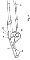
- the closure of the surgical clips to the correct position is set by a first end stop formed by the stop face 55 of the pusher 50 abutting the crimping lever 20.
- the position of this first end stop is not adjustable, being governed by the dimensions of the pusher 50 and the crimping lever 20.
- the locating plate 110 provides a second end stop feature by limiting movement of the trigger 28.
- the position of this second end stop must be adjusted to match the first end stop position, during the assembly of the applicator.
- the second end stop feature provides the surgeon with clear, tactile feedback that the trigger has been depressed sufficiently to fully close and secure the surgical clip.
- An additional benefit of the second end stop is that it limits the force which the surgeon can apply via the trigger to the compound lever mechanism, which might otherwise damage the handle or other parts of the applicator.
- the adjustment of the position of the second end stop is made by moving the locating plate 110 within the handle 62 until the second end stop position matches the first end stop position.
- the locating plate 110 is then secured to the handle 62 with the locating plate screws 112.
- the applicator 10 is intended to be used single-handedly.
- the trigger 28 is intended to be operated by the first and second fingers with the handle 62 accommodating the remaining fingers.
- the trigger 28 When the trigger 28 is depressed it slides into the handle 62. There is minimal clearance between the trigger 28 and the handle 62. When the applicator is being used, the surgeon will be wearing surgical gloves. Any substantial gap between the trigger 28 and the handle 62 may result in the surgical glove becoming trapped and torn, which could create hygiene problems.
- Movement of the trigger 28 results in the actuating pegs 82 on the second end 76 of the first lever 72 being moved by the actuating slot 36 in the trigger 28.
- the first end 90 of the second lever 88 slides along the length of the actuating surface 78 of the first lever 72, thereby rotating the second lever 88 about the second pivot pin 96.
- Rotational movement of the second lever 88 causes the second end 92 of the second lever 88 to press against the end cap 104 of the transfer rod 44 causing linear movement of the transfer rod 44.
- a first end stop limits further movement of the crimping level 20.
- the first end stop is formed by the stop face 55 of the pusher 50 abutting the crimping lever 20. The first end stop ensures that the surgical clip is precisely closed to the correct position and is not "over-closed”.
- the second end stop is formed by the trigger directly contacting the locating plate, thus further limiting the stroke of the mechanism.
- the return spring 130 urges the transfer rod 44 and pusher 50 away from the second end 16 of the barrel 12.
- Linear movement of the transfer rod 44 and pusher 50 away from the second end 16 of the barrel 12 causes the slot 53 at the second end 54 of the pusher 50 to pull against the opening peg 24 of the crimping lever 20 causing rotational movement about the pivot point of the crimping lever 20.
- This movement of the crimping lever 20 results in the second crimping surface 22 of the crimping lever 20 opening away from the first crimping surface 18 at the second end 16 of the barrel 12.
Landscapes
- Health & Medical Sciences (AREA)
- Surgery (AREA)
- Life Sciences & Earth Sciences (AREA)
- Heart & Thoracic Surgery (AREA)
- Nuclear Medicine, Radiotherapy & Molecular Imaging (AREA)
- Vascular Medicine (AREA)
- Engineering & Computer Science (AREA)
- Biomedical Technology (AREA)
- Reproductive Health (AREA)
- Medical Informatics (AREA)
- Molecular Biology (AREA)
- Animal Behavior & Ethology (AREA)
- General Health & Medical Sciences (AREA)
- Public Health (AREA)
- Veterinary Medicine (AREA)
- Surgical Instruments (AREA)
Description
- This application relates to applicators for surgical clips, and more particularly to applicators for the insertion and closure of surgical clips.
- Such applicators are intended for single handed operation by an operating surgeon. Examples of such applicators are described in
international patent application publication numbers WO 2005/039422 andWO-A-01/12079 - Such clips may be used for sterilisation or other medical, orthopaedic or surgical purposes. An example is the "Filshie" clip which is disclosed in
GB patent number 2177748 - Certain known applicators for such clips, as disclosed for example in
WO 2005/039422 , use a pushrod and associated linkage mechanism to cause rotation of an articulated jaw to produce compression forces on a clip and to thereby compress the clip causing it to close, preferably with a latching action. The compression forces on the relatively slender pushrod cause radial reaction forces and consequent friction at the interface between the pushrod and the outer tube. This can result in the applicator mechanism sticking in the closed position thus causing problems for the operating surgeon in disengaging the applicator from the closed clip. - Another example of a known applicator is described in
DE 90 15 046US 3954108A . - A problem with known applicators is the need to adjust the travel of the mechanism in order to achieve correct closure of the clip to an accurate position; such adjustment can be costly to achieve. It is important that the surgical clip is closed to an accurate position. If the clip is closed too tightly, the tubular anatomy may be severed, requiring the surgeon to apply further clips to severed ends of the tubular anatomy. Conversely, if applied clips are not closed sufficiently tightly, the tubular anatomy may not be properly occluded.
- A further problem with known applicators is the requirement that the applicator must be made from expensive components in order to ensure that the surgical clips can be closed accurately, and to be able to perform many clip closure operations. In particular, in such an important piece of medical equipment, and especially one in which mechanical forces are transmitted (e.g. the force of the surgeon pulling the trigger, which is converted to a closing force on the clip), it is important that tolerances are carefully monitored and, if need be, adjusted in the manufacturing environment. This can be expensive, and increases the manufacturing cost of the applicator.
- Appropriate design of applicator and its constituent components can mitigate some of the issues associated with this.
- Other designs of applicators can require the surgeon to apply significant force to the trigger mechanism of the applicator in order to correctly close and latch the surgical clip, which can make the applicator difficult to manipulate and operate.
- It is often necessary for the applicator to be inserted into a cannula during "keyhole" surgery. Existing clip applicators have a "pistol" handgrip which can make them difficult to manipulate into the correct position whilst at the same time operating the applicator (in particular providing adequate manual closure force) to close the clip.
- It is an object of the invention to provide an applicator for surgical clips which requires less force to operate and to correctly close and secure a surgical clip than known applicators.
- Another object of the invention is to provide an applicator which can precisely close and secure surgical clips to an accurate position.
- A further object of the invention is to provide an applicator which may be more precisely manipulated than known applicators, whilst also being operable to close and secure accurately a surgical clip.
- A still further object of the invention is to provide an applicator for surgical clips which is of a simpler and more robust design to such known applicators.
- Yet another object of the invention is to provide an applicator for surgical clips which is easier and cheaper to manufacture than existing applicators
- Such an applicator may be partially or completely disposable.
- According to the invention there is provided a hand-operable surgical clip applicator, the applicator comprising a barrel having a first end and a second end, the second end formed as a first crimping surface and being able to accommodate a surgical clip; a crimping lever, the crimping lever pivotally connected to the barrel, the crimping lever having a second crimping surface and an opening peg integrally formed therewith, the second crimping surface being in opposition to the first crimping surface, the first crimping surface and the second crimping surface being biased away from one another; and a pushrod, which may abut, and in use does abut, the crimping lever and constrains the opening peg, the pushrod being slidably located within the barrel; wherein the hand-operable surgical clip applicator is configured such that movement of the pushrod towards the second end of the barrel causes the pushrod to push the crimping lever, further causing the second crimping surface to close onto the first crimping surface, thereby in use urging a surgical clip from an open position towards a closed position, the pushrod comprising a transfer rod and a pusher, the pusher having a stop face, the transfer rod and pusher being slidably located within the barrel, the pusher including a slot through which a portion of the opening peg extends, wherein movement of the pushrod away from the second end of the barrel causes a surface formed by the slot in the pusher to pull the opening peg, further causing the second crimping surface to open away from the first crimping surface, and the hand-operable surgical clip applicator being characterised by the transfer rod and pusher being releasably connected together by a bayonet joint, and the pusher abutting the crimping lever and constraining the opening peg of the crimping lever.
- In known applicators it is common for the second end of the pushrod to slide over the crimping lever in order to rotate the crimping lever about a hinge point and urge the surgical clip from an open position to a closed position. This can result in the crimping lever becoming jammed in the closed position due to the frictional forces between the second end of the pushrod and the crimping lever.
- In the present invention, linear movement of the pushrod towards the second end of the barrel results in the second end of the pushrod pushing against the crimping lever. This causes a rotational movement of the crimping lever. During opening of the crimping surfaces, the second end of the pushrod acts to pull on the opening peg of the crimping lever to thereby cause the crimping lever to move such that the crimping surfaces are in an open position.
- Moreover, by connecting the pushrod and the pusher with a bayonet joint, the pusher experiences no bending forces which may cause it to bind in the barrel.
- Preferably the pushrod includes a hollow portion, with a return spring being accommodated within the hollow portion.
- Locating the return spring within the pushrod ensures that the surgical clip will be released from the applicator in the event that any part of the handle, trigger or actuating means should fail in use, thereby improving reliability of the applicator.
- Preferably the barrel is formed from a single piece of material.
- This can be achieved by utilising a forming process which facilitates the manufacture of the first crimping surface and the pivot on which the crimping lever is mounted from the same piece of tubing material. This avoids welding of barrel components, which has previously been necessary where the barrel and parts of the barrel have been made by machining.
- Forming the barrel from a single piece of material reduces the number of component parts in the applicator, making it easier to assemble and lowering the manufacturing costs.
- Preferably, the pusher is formed with sliding surface at each of the first and second ends, the sliding surfaces configured to slide within the internal surface of the barrel, the portion of the pusher between the first and second ends having a smaller diameter than each of the first and second ends.
- Such a pusher has a waisted profile which facilitates insertion of the pusher into the barrel during assembly of the applicator. The waisted feature also reduces the friction between the pusher and the barrel during operation of the applicator.
- Preferably the stroke of the pushrod is limited by the stop face of the pusher abutting the crimping lever.
- By governing the stroke of the pushrod, the stop face of the pusher abutting the crimping lever provides a first end stop to the travel of the trigger and the consequent rotation of the crimping lever. This prevents the crimping lever from closing the surgical clip past the nominal closed position. Such "over-closing" can result in the clip being closed too tightly.
- There now follows a description of preferred embodiments of the invention, by way of nonlimiting example, with reference being made to the accompanying drawings, in which:
-
Figure 1 shows a perspective view of the applicator of the invention; -
Figure 2 shows a partial sectional perspective view of the second end of the barrel of the applicator ofFigure 1 ; -
Figure 3 shows a sectional view of the handle of the applicator ofFigure 1 ; -
Figure 4 shows a partial sectional view of the bayonet joint of the applicator ofFigure 1 ; -
Figure 5 shows a detailed partial sectional view of the first end of the barrel of the applicator ofFigure 1 ; -
Figure 6 shows the operation of the first end stop of the applicator ofFigure 1 . - With reference to the drawings,
Figure 1 shows a hand-operable surgical clip applicator according to the invention. - The
applicator 10 comprises abarrel 12, atrigger 28 and ahandle 62. - The
barrel 12 has afirst end 14 and asecond end 16. The second end of thebarrel 16 is formed as afirst crimping surface 18 and accommodates a surgical clip. - The
barrel 12 is formed from a single piece of stainless steel tubing. - As shown in
Figure 2 , acrimping lever 20 is pivotally mounted at the second end of thebarrel 16. The crimpinglever 20 has a second crimpingsurface 22 and anopening peg 24 formed integrally. - The second crimping
surface 22 of the crimpinglever 20 and the first crimpingsurface 18 at the second end of thebarrel 16 act as a co-operative pair of jaws to crimp the surgical clip and to urge the clip from an open position to a closed position. - As shown in the figures, a
pushrod assembly 42 is slidably located within thebarrel 12 and comprises atransfer rod 44 and apusher 50. - The
transfer rod 44 has afirst end 46 and asecond end 48. Thepusher 50 has afirst end 52 and asecond end 54. - The
second end 54 of thepusher 50 is formed with aslot 53 which constrains theopening peg 24 of the crimpinglever 20 and astop face 55. Thefirst end 52 of thepusher 50 is operatively coupled to thesecond end 48 of thetransfer rod 44 by abayonet coupling 56, as shown inFigure 4 . - The
pusher 50 is waisted and is formed with sliding surfaces at each of the first and second ends 52, 54 which slide along the internal surface of thebarrel 12. This waisted feature facilitates assembly of thepusher 50 into the barrel; the waisted feature also reduces the friction between thepusher 50 and thebarrel 12, compared to if the whole of thepusher 50 had a consistent radius along its length. - The
trigger 28 is co-located with thebarrel 12 and includes apressing surface 30 on each of two opposing sides of thebarrel 12. Each of thepressing surfaces 30 is sized to be operable by the first and second fingers of the surgeon's hand respectively. - The trigger is preferably moulded from a thermoplastic material.
- The
trigger 28 includes avisual indicator 32 in each side of thetrigger 28. Thevisual indicator 32 takes the form of a slot in each side of thetrigger 28 with areference mark 34 moulded into the side surface of thetrigger 28. - The
visual indicator 32 provides a visual indication of an intermediate or "half closed" trigger position. When thetrigger 28 is depressed such that thereference mark 34 is aligned with a locatingplate 110, thetrigger 28 is "half closed". This can be important as it allows the surgeon to operate theapplicator 10 to hold and partially close the surgical clip without latching the clip, thus enabling the applicator and the clip to be inserted through the cannula prior to being positioned, closed and secured. - The
trigger 28 further includes anactuating slot 36 on each side of the trigger which is part of a lever mechanism. - The
handle 62 is formed in two parts. Thehandle 62 is preferably moulded from a thermoplastic material. - The
handle 62 includes afirst lever 72 and asecond lever 88. Thefirst lever 72 has afirst end 74 and asecond end 76. Thesecond lever 88 has afirst end 90, asecond end 92 and acentre region 94. - The
first end 74 of thefirst lever 72 is pivotally connected to thehandle 62 by afirst pivot 80. Thesecond end 76 of thefirst lever 72 is slidably connected to thetrigger 28. Two actuating pegs 82 formed on opposing sides of thesecond end 76 of thefirst lever 72 engage with theactuating slot 36 of thetrigger 28. - The
first lever 72 is formed with a U-shaped cross-section. Thefirst lever 72 is preferably moulded from a thermoplastic material. - The
centre region 94 of thesecond lever 88 is pivotally connected to thehandle 62 by asecond pivot pin 96. Thefirst end 90 of thesecond lever 88 is arranged to slide along the length of thefirst lever 72 with thefirst end 90 of thesecond lever 88 located within the U-shaped profile of thefirst lever 72. Thesecond end 92 of thesecond lever 88 presses against the first end of thetransfer rod 46. - The
second lever 88 is preferably formed from stainless steel. - The
first lever 72 and thesecond lever 88 are configured to provide a mechanical advantage between thetrigger 28 and thetransfer rod 46. -
Figure 5 shows a detail view of thefirst end 14 ofbarrel 12. - A
barrel pin 122 secures thefirst end 14 of thebarrel 12 to thehandle 62. - The locating
plate 110 is secured to thefirst end 14 of thebarrel 12 by the retainingpin 114. The retainingpin 114 may be a nut and bolt or an alternative type of fastener. - The retaining
pin 114 passes through a hole in thefirst end 14 of thebarrel 12 and through aslot 128 in thetransfer rod 44. - The
slot 128 in thetransfer rod 44 allows for the linear movement of thetransfer rod 44. - The locating
plate 110 is secured to the handle by two locating plate screws 112. The locating plate screws 112 pass through a slot in the locatingplate 110. The slot in the locating plate allows movement of the locatingplate 110 relative to thehandle 62 for calibration purposes. This calibration is described in more detail below. - An
end cap 104 is located in thefirst end 46 of thetransfer rod 44. Thesecond end 92 of thesecond lever 88 presses against theend cap 104. - A
return spring 130 is located within thefirst end 46 of thetransfer rod 44 between theend cap 104 and the retainingpin 114. - The closure of the surgical clips to the correct position is set by a first end stop formed by the
stop face 55 of thepusher 50 abutting the crimpinglever 20. The position of this first end stop is not adjustable, being governed by the dimensions of thepusher 50 and the crimpinglever 20. - The locating
plate 110 provides a second end stop feature by limiting movement of thetrigger 28. The position of this second end stop must be adjusted to match the first end stop position, during the assembly of the applicator. - The second end stop feature provides the surgeon with clear, tactile feedback that the trigger has been depressed sufficiently to fully close and secure the surgical clip.
- An additional benefit of the second end stop is that it limits the force which the surgeon can apply via the trigger to the compound lever mechanism, which might otherwise damage the handle or other parts of the applicator.
- The adjustment of the position of the second end stop is made by moving the locating
plate 110 within thehandle 62 until the second end stop position matches the first end stop position. The locatingplate 110 is then secured to thehandle 62 with the locating plate screws 112. - The
applicator 10 is intended to be used single-handedly. Thetrigger 28 is intended to be operated by the first and second fingers with thehandle 62 accommodating the remaining fingers. - When the
trigger 28 is depressed it slides into thehandle 62. There is minimal clearance between thetrigger 28 and thehandle 62. When the applicator is being used, the surgeon will be wearing surgical gloves. Any substantial gap between thetrigger 28 and thehandle 62 may result in the surgical glove becoming trapped and torn, which could create hygiene problems. - Movement of the
trigger 28 results in the actuating pegs 82 on thesecond end 76 of thefirst lever 72 being moved by theactuating slot 36 in thetrigger 28. - As the
first lever 72 rotates around thefirst pivot pin 80, thefirst end 90 of thesecond lever 88 slides along the length of the actuating surface 78 of thefirst lever 72, thereby rotating thesecond lever 88 about thesecond pivot pin 96. - Rotational movement of the
second lever 88 causes thesecond end 92 of thesecond lever 88 to press against theend cap 104 of thetransfer rod 44 causing linear movement of thetransfer rod 44. - Linear movement of the
transfer rod 44 andpusher 50 towards thesecond end 16 of thebarrel 12 causes thesecond end 54 of thepusher 50 to push against the crimpinglever 20 causing rotational movement about the pivot point of the crimpinglever 20. This movement of the crimpinglever 20 results in the second crimpingsurface 22 of the crimpinglever 20 closing onto the first crimpingsurface 18 at thesecond end 16 of thebarrel 12 resulting in the surgical clip being urged from an open position to a closed position. - When the second crimping
surface 22 reaches a position relative to the first crimpingsurface 18 in which the surgical clip is closed to the correct position, a first end stop limits further movement of the crimpinglevel 20. The first end stop is formed by thestop face 55 of thepusher 50 abutting the crimpinglever 20. The first end stop ensures that the surgical clip is precisely closed to the correct position and is not "over-closed". - Additional pressure applied to the trigger after the first end stop has been actuated results in a second end stop coming into operation. The second end stop is formed by the trigger directly contacting the locating plate, thus further limiting the stroke of the mechanism.
- When the
trigger 28 is released, thereturn spring 130 urges thetransfer rod 44 andpusher 50 away from thesecond end 16 of thebarrel 12. Linear movement of thetransfer rod 44 andpusher 50 away from thesecond end 16 of thebarrel 12 causes theslot 53 at thesecond end 54 of thepusher 50 to pull against theopening peg 24 of the crimpinglever 20 causing rotational movement about the pivot point of the crimpinglever 20. This movement of the crimpinglever 20 results in the second crimpingsurface 22 of the crimpinglever 20 opening away from the first crimpingsurface 18 at thesecond end 16 of thebarrel 12.
Claims (5)
- A hand-operable surgical clip applicator (10), the applicator (10) comprising:a barrel (12) having a first end (14) and a second end (16), the second end (16) formed as a first crimping surface (18) and being able to accommodate a surgical clip;a crimping lever (20), the crimping lever (20) pivotally connected to the barrel (12), the crimping lever (20) having a second crimping surface (22) and an opening peg (24) integrally formed therewith, the second crimping surface (22) being in opposition to the first crimping surface (18), the first crimping surface (18) and the second crimping surface (22) being biased away from one another; anda pushrod (42), which may abut, and in use does abut, the crimping lever (20) and constrains the opening peg (24), the pushrod (42) being slidably located within the barrel (12);wherein the hand-operable surgical clip applicator (10) is configured such that movement of the pushrod (42) towards the second end (16) of the barrel (12) causes the pushrod (42) to push the crimping lever (20), further causing the second crimping surface (22) to close onto the first crimping surface (18), thereby in use urging a surgical clip from an open position towards a closed position,the pushrod (42) comprising a transfer rod (44) and a pusher (50), the pusher (50) having a stop face (55), the transfer rod (44) and pusher (50) being slidably located within the barrel, the pusher (50) including a slot (53) through which a portion of the opening peg (24) extends, wherein movement of the pushrod (42) away from the second end (16) of the barrel (12) causes a surface formed by the slot (53) in the pusher (50) to pull the opening peg (24), further causing the second crimping surface (22) to open away from the first crimping surface (18), andthe hand-operable surgical clip applicator (10) being characterised by the transfer rod (44) and pusher (50) being releasably connected together by a bayonet joint (56), and the pusher (50) abutting the crimping lever (20) and constraining the opening peg (24) of the crimping lever (20).
- An applicator (10) as claimed in Claim 1 in which the pushrod (42) includes a hollow portion, with a return spring (130) being accommodated within the hollow portion.
- An applicator (10) as claimed in Claim 1 in which the barrel (12) is formed from a single piece of material.
- An applicator (10) as claimed in Claim 1, the pusher (50) being formed with sliding surfaces at each of first and second end (52, 54), the sliding surfaces configured to slide within the internal surface of the barrel (12), the portion of the pusher (50) between the first and second ends (52, 54) having a smaller diameter than each of the first and second ends (52, 54).
- An applicator (10) as claimed in Claim 4 in which a stroke of the pushrod (42) is limited by the stop face (55) of the pusher (50) abutting the crimping lever (20).
Applications Claiming Priority (3)
| Application Number | Priority Date | Filing Date | Title |
|---|---|---|---|
| GBGB0818101.8A GB0818101D0 (en) | 2008-10-03 | 2008-10-03 | Applicator for surgical clips |
| EP09740924.7A EP2355715B1 (en) | 2008-10-03 | 2009-10-02 | Applicator for surgical clips |
| PCT/GB2009/002347 WO2010038030A2 (en) | 2008-10-03 | 2009-10-02 | Applicator for surgical clips |
Related Parent Applications (2)
| Application Number | Title | Priority Date | Filing Date |
|---|---|---|---|
| EP09740924.7A Division-Into EP2355715B1 (en) | 2008-10-03 | 2009-10-02 | Applicator for surgical clips |
| EP09740924.7A Division EP2355715B1 (en) | 2008-10-03 | 2009-10-02 | Applicator for surgical clips |
Publications (2)
| Publication Number | Publication Date |
|---|---|
| EP2835104A1 EP2835104A1 (en) | 2015-02-11 |
| EP2835104B1 true EP2835104B1 (en) | 2021-09-01 |
Family
ID=40019986
Family Applications (2)
| Application Number | Title | Priority Date | Filing Date |
|---|---|---|---|
| EP14189734.8A Active EP2835104B1 (en) | 2008-10-03 | 2009-10-02 | Applicator for surgical clips |
| EP09740924.7A Active EP2355715B1 (en) | 2008-10-03 | 2009-10-02 | Applicator for surgical clips |
Family Applications After (1)
| Application Number | Title | Priority Date | Filing Date |
|---|---|---|---|
| EP09740924.7A Active EP2355715B1 (en) | 2008-10-03 | 2009-10-02 | Applicator for surgical clips |
Country Status (9)
| Country | Link |
|---|---|
| US (2) | US9451966B2 (en) |
| EP (2) | EP2835104B1 (en) |
| AU (2) | AU2009299569B2 (en) |
| CA (2) | CA2869043C (en) |
| DK (2) | DK2355715T3 (en) |
| ES (1) | ES2544489T3 (en) |
| GB (1) | GB0818101D0 (en) |
| PT (1) | PT2355715E (en) |
| WO (1) | WO2010038030A2 (en) |
Families Citing this family (66)
| Publication number | Priority date | Publication date | Assignee | Title |
|---|---|---|---|---|
| US8465502B2 (en) | 2008-08-25 | 2013-06-18 | Covidien Lp | Surgical clip applier and method of assembly |
| US8267944B2 (en) | 2008-08-29 | 2012-09-18 | Tyco Healthcare Group Lp | Endoscopic surgical clip applier with lock out |
| US9358015B2 (en) | 2008-08-29 | 2016-06-07 | Covidien Lp | Endoscopic surgical clip applier with wedge plate |
| US9186136B2 (en) | 2009-12-09 | 2015-11-17 | Covidien Lp | Surgical clip applier |
| US8403945B2 (en) | 2010-02-25 | 2013-03-26 | Covidien Lp | Articulating endoscopic surgical clip applier |
| US8968337B2 (en) | 2010-07-28 | 2015-03-03 | Covidien Lp | Articulating clip applier |
| WO2012106398A1 (en) | 2011-02-01 | 2012-08-09 | St. Jude Medical, Inc. | Apparatus and method for heart valve repair |
| DE102011081464A1 (en) * | 2011-08-24 | 2013-02-28 | Karl Storz Gmbh & Co. Kg | Tool for a micro-invasive-surgical instrument |
| US20130131697A1 (en) | 2011-11-21 | 2013-05-23 | Covidien Lp | Surgical clip applier |
| US9364216B2 (en) | 2011-12-29 | 2016-06-14 | Covidien Lp | Surgical clip applier with integrated clip counter |
| WO2013112795A1 (en) | 2012-01-25 | 2013-08-01 | St. Jude Medical, Inc. | Apparatus and method for heart valve repair |
| WO2013112797A2 (en) | 2012-01-25 | 2013-08-01 | St. Jude Medical, Inc. | Apparatus and method for heart valve repair |
| ES2631652T3 (en) | 2012-02-02 | 2017-09-01 | St. Jude Medical, Cardiology Division, Inc. | Device for repairing a heart valve |
| US9408610B2 (en) | 2012-05-04 | 2016-08-09 | Covidien Lp | Surgical clip applier with dissector |
| US9532787B2 (en) | 2012-05-31 | 2017-01-03 | Covidien Lp | Endoscopic clip applier |
| US10105219B2 (en) | 2012-08-02 | 2018-10-23 | St. Jude Medical, Cardiology Division, Inc. | Mitral valve leaflet clip |
| US9662205B2 (en) | 2012-08-02 | 2017-05-30 | St. Jude Medical, Cardiology Division, Inc. | Apparatus and method for heart valve repair |
| US9125653B2 (en) | 2012-08-02 | 2015-09-08 | St. Jude Medical, Cardiology Division, Inc. | Flexible nosecone for percutaneous device |
| US9254141B2 (en) | 2012-08-02 | 2016-02-09 | St. Jude Medical, Inc. | Apparatus and method for heart valve repair |
| US9066710B2 (en) * | 2012-10-19 | 2015-06-30 | St. Jude Medical, Cardiology Division, Inc. | Apparatus and method for heart valve repair |
| US9113892B2 (en) | 2013-01-08 | 2015-08-25 | Covidien Lp | Surgical clip applier |
| US9642706B2 (en) | 2013-03-11 | 2017-05-09 | St. Jude Medical, Llc | Apparatus and method for heart valve repair |
| US9775624B2 (en) | 2013-08-27 | 2017-10-03 | Covidien Lp | Surgical clip applier |
| US9931124B2 (en) | 2015-01-07 | 2018-04-03 | Covidien Lp | Reposable clip applier |
| WO2016112509A1 (en) | 2015-01-15 | 2016-07-21 | Covidien Lp | Endoscopic reposable surgical clip applier |
| US10292712B2 (en) | 2015-01-28 | 2019-05-21 | Covidien Lp | Surgical clip applier with integrated cutter |
| US10159491B2 (en) | 2015-03-10 | 2018-12-25 | Covidien Lp | Endoscopic reposable surgical clip applier |
| WO2017031493A1 (en) * | 2015-08-20 | 2017-02-23 | Lsi Solutions, Inc. | Adjustable motion limiter for a minimally invasive surgical device |
| US10660652B2 (en) | 2015-10-10 | 2020-05-26 | Covidien Lp | Endoscopic surgical clip applier |
| CA2998890A1 (en) | 2015-11-03 | 2017-05-11 | Covidien Lp | Endoscopic surgical clip applier |
| CN108348261B (en) | 2015-11-10 | 2021-03-16 | 柯惠有限合伙公司 | Reusable Endoscopic Surgical Clip Applier |
| US10905425B2 (en) | 2015-11-10 | 2021-02-02 | Covidien Lp | Endoscopic reposable surgical clip applier |
| US10390831B2 (en) | 2015-11-10 | 2019-08-27 | Covidien Lp | Endoscopic reposable surgical clip applier |
| AU2016386597A1 (en) | 2016-01-11 | 2018-07-05 | Covidien Lp | Endoscopic reposable surgical clip applier |
| JP6634521B2 (en) | 2016-01-18 | 2020-01-22 | コヴィディエン リミテッド パートナーシップ | Endoscopic surgical clip applier |
| CA2958160A1 (en) | 2016-02-24 | 2017-08-24 | Covidien Lp | Endoscopic reposable surgical clip applier |
| WO2018027788A1 (en) | 2016-08-11 | 2018-02-15 | Covidien Lp | Endoscopic surgical clip applier and clip applying systems |
| US10639044B2 (en) | 2016-10-31 | 2020-05-05 | Covidien Lp | Ligation clip module and clip applier |
| US10660651B2 (en) | 2016-10-31 | 2020-05-26 | Covidien Lp | Endoscopic reposable surgical clip applier |
| US10932790B2 (en) | 2017-08-08 | 2021-03-02 | Covidien Lp | Geared actuation mechanism and surgical clip applier including the same |
| US10863992B2 (en) | 2017-08-08 | 2020-12-15 | Covidien Lp | Endoscopic surgical clip applier |
| US10786262B2 (en) | 2017-08-09 | 2020-09-29 | Covidien Lp | Endoscopic reposable surgical clip applier |
| US10786263B2 (en) | 2017-08-15 | 2020-09-29 | Covidien Lp | Endoscopic reposable surgical clip applier |
| US10835341B2 (en) | 2017-09-12 | 2020-11-17 | Covidien Lp | Endoscopic surgical clip applier and handle assemblies for use therewith |
| US10835260B2 (en) * | 2017-09-13 | 2020-11-17 | Covidien Lp | Endoscopic surgical clip applier and handle assemblies for use therewith |
| US10945734B2 (en) | 2017-11-03 | 2021-03-16 | Covidien Lp | Rotation knob assemblies and surgical instruments including the same |
| US11116513B2 (en) | 2017-11-03 | 2021-09-14 | Covidien Lp | Modular surgical clip cartridge |
| US11376015B2 (en) | 2017-11-03 | 2022-07-05 | Covidien Lp | Endoscopic surgical clip applier and handle assemblies for use therewith |
| US10932791B2 (en) * | 2017-11-03 | 2021-03-02 | Covidien Lp | Reposable multi-fire surgical clip applier |
| US10743887B2 (en) | 2017-12-13 | 2020-08-18 | Covidien Lp | Reposable multi-fire surgical clip applier |
| US10849630B2 (en) | 2017-12-13 | 2020-12-01 | Covidien Lp | Reposable multi-fire surgical clip applier |
| US11051827B2 (en) | 2018-01-16 | 2021-07-06 | Covidien Lp | Endoscopic surgical instrument and handle assemblies for use therewith |
| US10993721B2 (en) | 2018-04-25 | 2021-05-04 | Covidien Lp | Surgical clip applier |
| US10786273B2 (en) | 2018-07-13 | 2020-09-29 | Covidien Lp | Rotation knob assemblies for handle assemblies |
| US11259887B2 (en) | 2018-08-10 | 2022-03-01 | Covidien Lp | Feedback mechanisms for handle assemblies |
| US11253267B2 (en) | 2018-08-13 | 2022-02-22 | Covidien Lp | Friction reduction mechanisms for handle assemblies |
| US11278267B2 (en) | 2018-08-13 | 2022-03-22 | Covidien Lp | Latch assemblies and surgical instruments including the same |
| US11033256B2 (en) | 2018-08-13 | 2021-06-15 | Covidien Lp | Linkage assembly for reusable surgical handle assemblies |
| US11051828B2 (en) | 2018-08-13 | 2021-07-06 | Covidien Lp | Rotation knob assemblies and surgical instruments including same |
| US11147566B2 (en) | 2018-10-01 | 2021-10-19 | Covidien Lp | Endoscopic surgical clip applier |
| US11524398B2 (en) | 2019-03-19 | 2022-12-13 | Covidien Lp | Gear drive mechanisms for surgical instruments |
| US11779340B2 (en) | 2020-01-02 | 2023-10-10 | Covidien Lp | Ligation clip loading device |
| US11723669B2 (en) | 2020-01-08 | 2023-08-15 | Covidien Lp | Clip applier with clip cartridge interface |
| US12114866B2 (en) | 2020-03-26 | 2024-10-15 | Covidien Lp | Interoperative clip loading device |
| CA3188045A1 (en) * | 2020-08-24 | 2022-03-03 | Janet L. F. Phillips | Surgical tissue orientation clip, delivery device, system and method using the same |
| US12419648B2 (en) | 2022-09-26 | 2025-09-23 | Covidien Lp | Two-part fasteners for surgical clip appliers and surgical clip appliers for deploying the same |
Citations (2)
| Publication number | Priority date | Publication date | Assignee | Title |
|---|---|---|---|---|
| US3954108A (en) * | 1972-11-03 | 1976-05-04 | Davis Hugh J | Occlusion clip and instrument for applying same |
| US20070084897A1 (en) * | 2003-05-20 | 2007-04-19 | Shelton Frederick E Iv | Articulating surgical stapling instrument incorporating a two-piece e-beam firing mechanism |
Family Cites Families (43)
| Publication number | Priority date | Publication date | Assignee | Title |
|---|---|---|---|---|
| US3775825A (en) | 1971-08-24 | 1973-12-04 | Levaux R | Clip applicator |
| US4369788A (en) * | 1980-01-31 | 1983-01-25 | Goald Harold J | Reversed forceps for microdisc surgery |
| US4712549A (en) | 1985-07-01 | 1987-12-15 | Edward Weck & Co. | Automatic hemostatic clip applier |
| GB2177748B (en) | 1985-07-10 | 1988-11-16 | Femcare Ltd | Sexual sterilisation device |
| US5542949A (en) | 1987-05-14 | 1996-08-06 | Yoon; Inbae | Multifunctional clip applier instrument |
| US5100420A (en) * | 1989-07-18 | 1992-03-31 | United States Surgical Corporation | Apparatus and method for applying surgical clips in laparoscopic or endoscopic procedures |
| DE9015046U1 (en) * | 1990-07-30 | 1991-01-17 | Ethicon GmbH & Co KG, 2000 Norderstedt | Ligature clip applicator |
| DE4024106C1 (en) | 1990-07-30 | 1992-04-23 | Ethicon Gmbh & Co Kg, 2000 Norderstedt, De | |
| CA2133687C (en) | 1992-10-09 | 2007-03-27 | David T. Green | Surgical clip applier |
| DE4307539B4 (en) | 1993-03-10 | 2005-08-25 | Karl Storz Gmbh & Co. Kg | Medical forceps |
| GR1002376B (en) | 1993-04-29 | 1996-06-25 | Ethicon Inc. | Combined open procedure endoscopic mechanism and method of use. |
| US5503320A (en) * | 1993-08-19 | 1996-04-02 | United States Surgical Corporation | Surgical apparatus with indicator |
| US5501698A (en) | 1994-02-14 | 1996-03-26 | Heartport, Inc. | Endoscopic microsurgical instruments and methods |
| CA2147800C (en) | 1994-05-26 | 2006-07-11 | John Charles Robertson | Circular anastomosis device |
| US5637108A (en) | 1994-06-15 | 1997-06-10 | United States Surgical Corporation | Surgical handle having a controlled leak passage |
| US5632432A (en) | 1994-12-19 | 1997-05-27 | Ethicon Endo-Surgery, Inc. | Surgical instrument |
| DE69518306T2 (en) | 1995-03-15 | 2001-01-25 | Ethicon Endo-Surgery, Inc. | Device for attaching surgical clips |
| US5700270A (en) | 1995-10-20 | 1997-12-23 | United States Surgical Corporation | Surgical clip applier |
| US6024748A (en) | 1996-07-23 | 2000-02-15 | United States Surgical Corporation | Singleshot anastomosis instrument with detachable loading unit and method |
| US6162207A (en) * | 1997-08-18 | 2000-12-19 | Asahi Kogaku Kogyo Kabushiki Kaisha | Operating unit for endoscopic treatment tool |
| US6241740B1 (en) * | 1998-04-09 | 2001-06-05 | Origin Medsystems, Inc. | System and method of use for ligating and cutting tissue |
| GB9919170D0 (en) | 1999-08-14 | 1999-10-20 | Femcare Ltd | Applicator for surgical clips |
| US6716226B2 (en) * | 2001-06-25 | 2004-04-06 | Inscope Development, Llc | Surgical clip |
| DE60134787D1 (en) * | 2001-04-06 | 2008-08-21 | Covidien Ag | DEVICE FOR SEALING AND SHARING A VESSEL |
| US20020165549A1 (en) * | 2001-04-30 | 2002-11-07 | Medtronic, Inc. | Surgical instrument and attachment |
| US7211091B2 (en) * | 2002-08-27 | 2007-05-01 | Pilling Weck Incorporated | Fingertip-actuated surgical clip applier and related methods |
| US7052504B2 (en) * | 2002-11-19 | 2006-05-30 | Teleflex Incorporated | Automated-feed surgical clip applier and related methods |
| US7597693B2 (en) * | 2003-06-13 | 2009-10-06 | Covidien Ag | Vessel sealer and divider for use with small trocars and cannulas |
| US7434715B2 (en) | 2003-09-29 | 2008-10-14 | Ethicon Endo-Surgery, Inc. | Surgical stapling instrument having multistroke firing with opening lockout |
| CA2542011C (en) | 2003-10-15 | 2009-12-08 | Femcare Limited | Applicator |
| US7875040B2 (en) * | 2003-10-15 | 2011-01-25 | Femcare Limited | Visual indication of a trigger intermediate position on an applicator |
| US20050139636A1 (en) * | 2003-12-30 | 2005-06-30 | Schwemberger Richard F. | Replaceable cartridge module for a surgical stapling and cutting instrument |
| JP5047799B2 (en) | 2004-10-08 | 2012-10-10 | タイコ ヘルスケア グループ リミテッド パートナーシップ | Endoscopic surgical clip applier |
| US8038686B2 (en) | 2005-04-14 | 2011-10-18 | Ethicon Endo-Surgery, Inc. | Clip applier configured to prevent clip fallout |
| US20070191868A1 (en) | 2005-08-25 | 2007-08-16 | Microline Pentax Inc. | Indicating system for clip applying device |
| US7552854B2 (en) * | 2006-05-19 | 2009-06-30 | Applied Medical Resources Corporation | Surgical stapler with firing lock mechanism |
| EP1913881B1 (en) * | 2006-10-17 | 2014-06-11 | Covidien LP | Apparatus for applying surgical clips |
| US20080188872A1 (en) | 2006-12-13 | 2008-08-07 | Michael Duff | Multi-mode clip applier, and associated method |
| US8893946B2 (en) | 2007-03-28 | 2014-11-25 | Ethicon Endo-Surgery, Inc. | Laparoscopic tissue thickness and clamp load measuring devices |
| CA2682958C (en) | 2007-04-11 | 2015-11-10 | Tyco Healthcare Group Lp | Surgical clip applier |
| US8424738B2 (en) * | 2008-06-04 | 2013-04-23 | Covidien Lp | Attachable clamp for surgical stapler |
| US7789283B2 (en) * | 2008-06-06 | 2010-09-07 | Tyco Healthcare Group Lp | Knife/firing rod connection for surgical instrument |
| US8007513B2 (en) * | 2008-06-12 | 2011-08-30 | Ethicon Endo-Surgery, Inc. | Partially reusable surgical stapler |
-
2008
- 2008-10-03 GB GBGB0818101.8A patent/GB0818101D0/en not_active Ceased
-
2009
- 2009-10-02 ES ES09740924.7T patent/ES2544489T3/en active Active
- 2009-10-02 AU AU2009299569A patent/AU2009299569B2/en active Active
- 2009-10-02 EP EP14189734.8A patent/EP2835104B1/en active Active
- 2009-10-02 DK DK09740924.7T patent/DK2355715T3/en active
- 2009-10-02 WO PCT/GB2009/002347 patent/WO2010038030A2/en not_active Ceased
- 2009-10-02 PT PT97409247T patent/PT2355715E/en unknown
- 2009-10-02 EP EP09740924.7A patent/EP2355715B1/en active Active
- 2009-10-02 DK DK14189734.8T patent/DK2835104T3/en active
- 2009-10-02 CA CA2869043A patent/CA2869043C/en active Active
- 2009-10-02 CA CA2739356A patent/CA2739356C/en active Active
- 2009-10-02 US US13/121,731 patent/US9451966B2/en active Active
-
2014
- 2014-08-07 AU AU2014210618A patent/AU2014210618B2/en active Active
-
2015
- 2015-04-09 US US14/682,670 patent/US10092296B2/en active Active
Patent Citations (2)
| Publication number | Priority date | Publication date | Assignee | Title |
|---|---|---|---|---|
| US3954108A (en) * | 1972-11-03 | 1976-05-04 | Davis Hugh J | Occlusion clip and instrument for applying same |
| US20070084897A1 (en) * | 2003-05-20 | 2007-04-19 | Shelton Frederick E Iv | Articulating surgical stapling instrument incorporating a two-piece e-beam firing mechanism |
Also Published As
| Publication number | Publication date |
|---|---|
| US20150265282A1 (en) | 2015-09-24 |
| AU2014210618A1 (en) | 2014-08-28 |
| AU2009299569A1 (en) | 2010-04-08 |
| CA2869043C (en) | 2016-05-17 |
| CA2869043A1 (en) | 2010-04-08 |
| ES2544489T3 (en) | 2015-08-31 |
| EP2355715B1 (en) | 2015-06-24 |
| AU2009299569B2 (en) | 2013-03-07 |
| DK2835104T3 (en) | 2021-09-13 |
| US20110313432A1 (en) | 2011-12-22 |
| EP2355715A2 (en) | 2011-08-17 |
| CA2739356A1 (en) | 2010-04-08 |
| CA2739356C (en) | 2016-01-12 |
| DK2355715T3 (en) | 2015-07-27 |
| PT2355715E (en) | 2015-09-16 |
| GB0818101D0 (en) | 2008-11-05 |
| US10092296B2 (en) | 2018-10-09 |
| AU2014210618B2 (en) | 2015-11-05 |
| US9451966B2 (en) | 2016-09-27 |
| WO2010038030A2 (en) | 2010-04-08 |
| EP2835104A1 (en) | 2015-02-11 |
| WO2010038030A3 (en) | 2010-06-24 |
Similar Documents
| Publication | Publication Date | Title |
|---|---|---|
| EP2835104A1 (en) | Applicator for surgical clips | |
| EP1755461B1 (en) | Suture passing device | |
| US10842524B2 (en) | Lockout mechanisms for surgical devices | |
| US10675112B2 (en) | Endoscopic surgical clip applier including counter assembly | |
| EP3441018B1 (en) | Surgical device with overload mechanism | |
| CN1853579B (en) | Surgical Clip Applicator | |
| US5364397A (en) | Spinal coupler seater with dual jaws and an independent plunger | |
| EP3703588B1 (en) | Surgical appliance | |
| CN105935305B (en) | Surgical instruments for dissecting tissue | |
| CN101664330B (en) | Endoscopic surgical clip applier with clip holder | |
| WO2013043497A2 (en) | Suture passer device and suture needle | |
| CN108472048B (en) | Laminectomy clamp with improved lever mechanism | |
| US20010027312A1 (en) | Handle for a medical instrument | |
| US5439461A (en) | Grip for a surgical instrument | |
| HK40031565A (en) | Surgical appliance | |
| MXPA06004252A (en) | Surgical clip applier ratchet mechanism | |
| MXPA06004253A (en) | Surgical clip advancement and alignment mechanism |
Legal Events
| Date | Code | Title | Description |
|---|---|---|---|
| PUAI | Public reference made under article 153(3) epc to a published international application that has entered the european phase |
Free format text: ORIGINAL CODE: 0009012 |
|
| 17P | Request for examination filed |
Effective date: 20141021 |
|
| AC | Divisional application: reference to earlier application |
Ref document number: 2355715 Country of ref document: EP Kind code of ref document: P |
|
| AK | Designated contracting states |
Kind code of ref document: A1 Designated state(s): AT BE BG CH CY CZ DE DK EE ES FI FR GB GR HR HU IE IS IT LI LT LU LV MC MK MT NL NO PL PT RO SE SI SK SM TR |
|
| R17P | Request for examination filed (corrected) |
Effective date: 20150804 |
|
| RBV | Designated contracting states (corrected) |
Designated state(s): AT BE BG CH CY CZ DE DK EE ES FI FR GB GR HR HU IE IS IT LI LT LU LV MC MK MT NL NO PL PT RO SE SI SK SM TR |
|
| STAA | Information on the status of an ep patent application or granted ep patent |
Free format text: STATUS: EXAMINATION IS IN PROGRESS |
|
| 17Q | First examination report despatched |
Effective date: 20170510 |
|
| RAP1 | Party data changed (applicant data changed or rights of an application transferred) |
Owner name: FEMCARE-NIKOMED LIMITED |
|
| GRAP | Despatch of communication of intention to grant a patent |
Free format text: ORIGINAL CODE: EPIDOSNIGR1 |
|
| STAA | Information on the status of an ep patent application or granted ep patent |
Free format text: STATUS: GRANT OF PATENT IS INTENDED |
|
| RIC1 | Information provided on ipc code assigned before grant |
Ipc: A61B 90/00 20160101ALN20201201BHEP Ipc: A61B 17/128 20060101AFI20201201BHEP Ipc: A61B 17/00 20060101ALN20201201BHEP Ipc: A61B 17/29 20060101ALN20201201BHEP |
|
| INTG | Intention to grant announced |
Effective date: 20201214 |
|
| GRAJ | Information related to disapproval of communication of intention to grant by the applicant or resumption of examination proceedings by the epo deleted |
Free format text: ORIGINAL CODE: EPIDOSDIGR1 |
|
| STAA | Information on the status of an ep patent application or granted ep patent |
Free format text: STATUS: EXAMINATION IS IN PROGRESS |
|
| GRAP | Despatch of communication of intention to grant a patent |
Free format text: ORIGINAL CODE: EPIDOSNIGR1 |
|
| STAA | Information on the status of an ep patent application or granted ep patent |
Free format text: STATUS: GRANT OF PATENT IS INTENDED |
|
| INTC | Intention to grant announced (deleted) | ||
| RIC1 | Information provided on ipc code assigned before grant |
Ipc: A61B 90/00 20160101ALN20210315BHEP Ipc: A61B 17/29 20060101ALN20210315BHEP Ipc: A61B 17/00 20060101ALN20210315BHEP Ipc: A61B 17/128 20060101AFI20210315BHEP |
|
| INTG | Intention to grant announced |
Effective date: 20210329 |
|
| RAP3 | Party data changed (applicant data changed or rights of an application transferred) |
Owner name: FEMCARE LIMITED |
|
| GRAS | Grant fee paid |
Free format text: ORIGINAL CODE: EPIDOSNIGR3 |
|
| GRAA | (expected) grant |
Free format text: ORIGINAL CODE: 0009210 |
|
| STAA | Information on the status of an ep patent application or granted ep patent |
Free format text: STATUS: THE PATENT HAS BEEN GRANTED |
|
| AC | Divisional application: reference to earlier application |
Ref document number: 2355715 Country of ref document: EP Kind code of ref document: P |
|
| AK | Designated contracting states |
Kind code of ref document: B1 Designated state(s): AT BE BG CH CY CZ DE DK EE ES FI FR GB GR HR HU IE IS IT LI LT LU LV MC MK MT NL NO PL PT RO SE SI SK SM TR |
|
| REG | Reference to a national code |
Ref country code: GB Ref legal event code: FG4D |
|
| REG | Reference to a national code |
Ref country code: DK Ref legal event code: T3 Effective date: 20210907 |
|
| REG | Reference to a national code |
Ref country code: AT Ref legal event code: REF Ref document number: 1425365 Country of ref document: AT Kind code of ref document: T Effective date: 20210915 Ref country code: CH Ref legal event code: EP |
|
| REG | Reference to a national code |
Ref country code: DE Ref legal event code: R096 Ref document number: 602009064006 Country of ref document: DE |
|
| REG | Reference to a national code |
Ref country code: SE Ref legal event code: TRGR |
|
| REG | Reference to a national code |
Ref country code: IE Ref legal event code: FG4D |
|
| REG | Reference to a national code |
Ref country code: NL Ref legal event code: FP |
|
| REG | Reference to a national code |
Ref country code: FI Ref legal event code: FGE |
|
| REG | Reference to a national code |
Ref country code: LT Ref legal event code: MG9D |
|
| PG25 | Lapsed in a contracting state [announced via postgrant information from national office to epo] |
Ref country code: HR Free format text: LAPSE BECAUSE OF FAILURE TO SUBMIT A TRANSLATION OF THE DESCRIPTION OR TO PAY THE FEE WITHIN THE PRESCRIBED TIME-LIMIT Effective date: 20210901 Ref country code: LT Free format text: LAPSE BECAUSE OF FAILURE TO SUBMIT A TRANSLATION OF THE DESCRIPTION OR TO PAY THE FEE WITHIN THE PRESCRIBED TIME-LIMIT Effective date: 20210901 Ref country code: BG Free format text: LAPSE BECAUSE OF FAILURE TO SUBMIT A TRANSLATION OF THE DESCRIPTION OR TO PAY THE FEE WITHIN THE PRESCRIBED TIME-LIMIT Effective date: 20211201 Ref country code: NO Free format text: LAPSE BECAUSE OF FAILURE TO SUBMIT A TRANSLATION OF THE DESCRIPTION OR TO PAY THE FEE WITHIN THE PRESCRIBED TIME-LIMIT Effective date: 20211201 Ref country code: ES Free format text: LAPSE BECAUSE OF FAILURE TO SUBMIT A TRANSLATION OF THE DESCRIPTION OR TO PAY THE FEE WITHIN THE PRESCRIBED TIME-LIMIT Effective date: 20210901 |
|
| REG | Reference to a national code |
Ref country code: AT Ref legal event code: MK05 Ref document number: 1425365 Country of ref document: AT Kind code of ref document: T Effective date: 20210901 |
|
| PG25 | Lapsed in a contracting state [announced via postgrant information from national office to epo] |
Ref country code: PL Free format text: LAPSE BECAUSE OF FAILURE TO SUBMIT A TRANSLATION OF THE DESCRIPTION OR TO PAY THE FEE WITHIN THE PRESCRIBED TIME-LIMIT Effective date: 20210901 Ref country code: LV Free format text: LAPSE BECAUSE OF FAILURE TO SUBMIT A TRANSLATION OF THE DESCRIPTION OR TO PAY THE FEE WITHIN THE PRESCRIBED TIME-LIMIT Effective date: 20210901 Ref country code: GR Free format text: LAPSE BECAUSE OF FAILURE TO SUBMIT A TRANSLATION OF THE DESCRIPTION OR TO PAY THE FEE WITHIN THE PRESCRIBED TIME-LIMIT Effective date: 20211202 |
|
| PG25 | Lapsed in a contracting state [announced via postgrant information from national office to epo] |
Ref country code: AT Free format text: LAPSE BECAUSE OF FAILURE TO SUBMIT A TRANSLATION OF THE DESCRIPTION OR TO PAY THE FEE WITHIN THE PRESCRIBED TIME-LIMIT Effective date: 20210901 |
|
| REG | Reference to a national code |
Ref country code: DE Ref legal event code: R119 Ref document number: 602009064006 Country of ref document: DE |
|
| REG | Reference to a national code |
Ref country code: CH Ref legal event code: PL |
|
| PG25 | Lapsed in a contracting state [announced via postgrant information from national office to epo] |
Ref country code: IS Free format text: LAPSE BECAUSE OF FAILURE TO SUBMIT A TRANSLATION OF THE DESCRIPTION OR TO PAY THE FEE WITHIN THE PRESCRIBED TIME-LIMIT Effective date: 20220101 Ref country code: SM Free format text: LAPSE BECAUSE OF FAILURE TO SUBMIT A TRANSLATION OF THE DESCRIPTION OR TO PAY THE FEE WITHIN THE PRESCRIBED TIME-LIMIT Effective date: 20210901 Ref country code: SK Free format text: LAPSE BECAUSE OF FAILURE TO SUBMIT A TRANSLATION OF THE DESCRIPTION OR TO PAY THE FEE WITHIN THE PRESCRIBED TIME-LIMIT Effective date: 20210901 Ref country code: RO Free format text: LAPSE BECAUSE OF FAILURE TO SUBMIT A TRANSLATION OF THE DESCRIPTION OR TO PAY THE FEE WITHIN THE PRESCRIBED TIME-LIMIT Effective date: 20210901 Ref country code: PT Free format text: LAPSE BECAUSE OF FAILURE TO SUBMIT A TRANSLATION OF THE DESCRIPTION OR TO PAY THE FEE WITHIN THE PRESCRIBED TIME-LIMIT Effective date: 20220103 Ref country code: EE Free format text: LAPSE BECAUSE OF FAILURE TO SUBMIT A TRANSLATION OF THE DESCRIPTION OR TO PAY THE FEE WITHIN THE PRESCRIBED TIME-LIMIT Effective date: 20210901 Ref country code: CZ Free format text: LAPSE BECAUSE OF FAILURE TO SUBMIT A TRANSLATION OF THE DESCRIPTION OR TO PAY THE FEE WITHIN THE PRESCRIBED TIME-LIMIT Effective date: 20210901 |
|
| PG25 | Lapsed in a contracting state [announced via postgrant information from national office to epo] |
Ref country code: MC Free format text: LAPSE BECAUSE OF FAILURE TO SUBMIT A TRANSLATION OF THE DESCRIPTION OR TO PAY THE FEE WITHIN THE PRESCRIBED TIME-LIMIT Effective date: 20210901 |
|
| PLBE | No opposition filed within time limit |
Free format text: ORIGINAL CODE: 0009261 |
|
| STAA | Information on the status of an ep patent application or granted ep patent |
Free format text: STATUS: NO OPPOSITION FILED WITHIN TIME LIMIT |
|
| PG25 | Lapsed in a contracting state [announced via postgrant information from national office to epo] |
Ref country code: LU Free format text: LAPSE BECAUSE OF NON-PAYMENT OF DUE FEES Effective date: 20211002 Ref country code: IT Free format text: LAPSE BECAUSE OF FAILURE TO SUBMIT A TRANSLATION OF THE DESCRIPTION OR TO PAY THE FEE WITHIN THE PRESCRIBED TIME-LIMIT Effective date: 20210901 Ref country code: DE Free format text: LAPSE BECAUSE OF NON-PAYMENT OF DUE FEES Effective date: 20220503 |
|
| 26N | No opposition filed |
Effective date: 20220602 |
|
| PG25 | Lapsed in a contracting state [announced via postgrant information from national office to epo] |
Ref country code: SI Free format text: LAPSE BECAUSE OF FAILURE TO SUBMIT A TRANSLATION OF THE DESCRIPTION OR TO PAY THE FEE WITHIN THE PRESCRIBED TIME-LIMIT Effective date: 20210901 Ref country code: LI Free format text: LAPSE BECAUSE OF NON-PAYMENT OF DUE FEES Effective date: 20211031 Ref country code: CH Free format text: LAPSE BECAUSE OF NON-PAYMENT OF DUE FEES Effective date: 20211031 |
|
| PG25 | Lapsed in a contracting state [announced via postgrant information from national office to epo] |
Ref country code: HU Free format text: LAPSE BECAUSE OF FAILURE TO SUBMIT A TRANSLATION OF THE DESCRIPTION OR TO PAY THE FEE WITHIN THE PRESCRIBED TIME-LIMIT; INVALID AB INITIO Effective date: 20091002 Ref country code: CY Free format text: LAPSE BECAUSE OF FAILURE TO SUBMIT A TRANSLATION OF THE DESCRIPTION OR TO PAY THE FEE WITHIN THE PRESCRIBED TIME-LIMIT Effective date: 20210901 |
|
| P01 | Opt-out of the competence of the unified patent court (upc) registered |
Effective date: 20230519 |
|
| PGFP | Annual fee paid to national office [announced via postgrant information from national office to epo] |
Ref country code: SE Payment date: 20231012 Year of fee payment: 15 |
|
| PG25 | Lapsed in a contracting state [announced via postgrant information from national office to epo] |
Ref country code: MK Free format text: LAPSE BECAUSE OF FAILURE TO SUBMIT A TRANSLATION OF THE DESCRIPTION OR TO PAY THE FEE WITHIN THE PRESCRIBED TIME-LIMIT Effective date: 20210901 |
|
| PG25 | Lapsed in a contracting state [announced via postgrant information from national office to epo] |
Ref country code: TR Free format text: LAPSE BECAUSE OF FAILURE TO SUBMIT A TRANSLATION OF THE DESCRIPTION OR TO PAY THE FEE WITHIN THE PRESCRIBED TIME-LIMIT Effective date: 20210901 |
|
| PG25 | Lapsed in a contracting state [announced via postgrant information from national office to epo] |
Ref country code: MT Free format text: LAPSE BECAUSE OF FAILURE TO SUBMIT A TRANSLATION OF THE DESCRIPTION OR TO PAY THE FEE WITHIN THE PRESCRIBED TIME-LIMIT Effective date: 20210901 |
|
| REG | Reference to a national code |
Ref country code: SE Ref legal event code: EUG |
|
| PGFP | Annual fee paid to national office [announced via postgrant information from national office to epo] |
Ref country code: DK Payment date: 20250923 Year of fee payment: 17 |
|
| PG25 | Lapsed in a contracting state [announced via postgrant information from national office to epo] |
Ref country code: SE Free format text: LAPSE BECAUSE OF NON-PAYMENT OF DUE FEES Effective date: 20241003 |
|
| PGFP | Annual fee paid to national office [announced via postgrant information from national office to epo] |
Ref country code: GB Payment date: 20250924 Year of fee payment: 17 |
|
| PGFP | Annual fee paid to national office [announced via postgrant information from national office to epo] |
Ref country code: IE Payment date: 20250922 Year of fee payment: 17 |
|
| PGFP | Annual fee paid to national office [announced via postgrant information from national office to epo] |
Ref country code: NL Payment date: 20251021 Year of fee payment: 17 |
|
| PGFP | Annual fee paid to national office [announced via postgrant information from national office to epo] |
Ref country code: FI Payment date: 20251023 Year of fee payment: 17 |
|
| PGFP | Annual fee paid to national office [announced via postgrant information from national office to epo] |
Ref country code: FR Payment date: 20251027 Year of fee payment: 17 |
|
| PGFP | Annual fee paid to national office [announced via postgrant information from national office to epo] |
Ref country code: BE Payment date: 20251021 Year of fee payment: 17 |