EP2834876B1 - Procédé de gestion de charge d'une batterie de traction et dispositifs correspondants - Google Patents
Procédé de gestion de charge d'une batterie de traction et dispositifs correspondants Download PDFInfo
- Publication number
- EP2834876B1 EP2834876B1 EP13715296.3A EP13715296A EP2834876B1 EP 2834876 B1 EP2834876 B1 EP 2834876B1 EP 13715296 A EP13715296 A EP 13715296A EP 2834876 B1 EP2834876 B1 EP 2834876B1
- Authority
- EP
- European Patent Office
- Prior art keywords
- compressor
- comp
- charging
- managing
- batt
- Prior art date
- Legal status (The legal status is an assumption and is not a legal conclusion. Google has not performed a legal analysis and makes no representation as to the accuracy of the status listed.)
- Not-in-force
Links
Images



Classifications
-
- B—PERFORMING OPERATIONS; TRANSPORTING
- B60—VEHICLES IN GENERAL
- B60H—ARRANGEMENTS OF HEATING, COOLING, VENTILATING OR OTHER AIR-TREATING DEVICES SPECIALLY ADAPTED FOR PASSENGER OR GOODS SPACES OF VEHICLES
- B60H1/00—Heating, cooling or ventilating devices
- B60H1/00357—Air-conditioning arrangements specially adapted for particular vehicles
- B60H1/00385—Air-conditioning arrangements specially adapted for particular vehicles for vehicles having an electrical drive, e.g. hybrid or fuel cell
-
- B—PERFORMING OPERATIONS; TRANSPORTING
- B60—VEHICLES IN GENERAL
- B60H—ARRANGEMENTS OF HEATING, COOLING, VENTILATING OR OTHER AIR-TREATING DEVICES SPECIALLY ADAPTED FOR PASSENGER OR GOODS SPACES OF VEHICLES
- B60H1/00—Heating, cooling or ventilating devices
- B60H1/32—Cooling devices
- B60H1/3204—Cooling devices using compression
- B60H1/3205—Control means therefor
- B60H1/3208—Vehicle drive related control of the compressor drive means, e.g. for fuel saving purposes
-
- B—PERFORMING OPERATIONS; TRANSPORTING
- B60—VEHICLES IN GENERAL
- B60L—PROPULSION OF ELECTRICALLY-PROPELLED VEHICLES; SUPPLYING ELECTRIC POWER FOR AUXILIARY EQUIPMENT OF ELECTRICALLY-PROPELLED VEHICLES; ELECTRODYNAMIC BRAKE SYSTEMS FOR VEHICLES IN GENERAL; MAGNETIC SUSPENSION OR LEVITATION FOR VEHICLES; MONITORING OPERATING VARIABLES OF ELECTRICALLY-PROPELLED VEHICLES; ELECTRIC SAFETY DEVICES FOR ELECTRICALLY-PROPELLED VEHICLES
- B60L1/00—Supplying electric power to auxiliary equipment of vehicles
- B60L1/003—Supplying electric power to auxiliary equipment of vehicles to auxiliary motors, e.g. for pumps, compressors
-
- B—PERFORMING OPERATIONS; TRANSPORTING
- B60—VEHICLES IN GENERAL
- B60L—PROPULSION OF ELECTRICALLY-PROPELLED VEHICLES; SUPPLYING ELECTRIC POWER FOR AUXILIARY EQUIPMENT OF ELECTRICALLY-PROPELLED VEHICLES; ELECTRODYNAMIC BRAKE SYSTEMS FOR VEHICLES IN GENERAL; MAGNETIC SUSPENSION OR LEVITATION FOR VEHICLES; MONITORING OPERATING VARIABLES OF ELECTRICALLY-PROPELLED VEHICLES; ELECTRIC SAFETY DEVICES FOR ELECTRICALLY-PROPELLED VEHICLES
- B60L1/00—Supplying electric power to auxiliary equipment of vehicles
- B60L1/02—Supplying electric power to auxiliary equipment of vehicles to electric heating circuits
-
- B—PERFORMING OPERATIONS; TRANSPORTING
- B60—VEHICLES IN GENERAL
- B60L—PROPULSION OF ELECTRICALLY-PROPELLED VEHICLES; SUPPLYING ELECTRIC POWER FOR AUXILIARY EQUIPMENT OF ELECTRICALLY-PROPELLED VEHICLES; ELECTRODYNAMIC BRAKE SYSTEMS FOR VEHICLES IN GENERAL; MAGNETIC SUSPENSION OR LEVITATION FOR VEHICLES; MONITORING OPERATING VARIABLES OF ELECTRICALLY-PROPELLED VEHICLES; ELECTRIC SAFETY DEVICES FOR ELECTRICALLY-PROPELLED VEHICLES
- B60L3/00—Electric devices on electrically-propelled vehicles for safety purposes; Monitoring operating variables, e.g. speed, deceleration or energy consumption
- B60L3/0023—Detecting, eliminating, remedying or compensating for drive train abnormalities, e.g. failures within the drive train
- B60L3/0069—Detecting, eliminating, remedying or compensating for drive train abnormalities, e.g. failures within the drive train relating to the isolation, e.g. ground fault or leak current
-
- B—PERFORMING OPERATIONS; TRANSPORTING
- B60—VEHICLES IN GENERAL
- B60L—PROPULSION OF ELECTRICALLY-PROPELLED VEHICLES; SUPPLYING ELECTRIC POWER FOR AUXILIARY EQUIPMENT OF ELECTRICALLY-PROPELLED VEHICLES; ELECTRODYNAMIC BRAKE SYSTEMS FOR VEHICLES IN GENERAL; MAGNETIC SUSPENSION OR LEVITATION FOR VEHICLES; MONITORING OPERATING VARIABLES OF ELECTRICALLY-PROPELLED VEHICLES; ELECTRIC SAFETY DEVICES FOR ELECTRICALLY-PROPELLED VEHICLES
- B60L3/00—Electric devices on electrically-propelled vehicles for safety purposes; Monitoring operating variables, e.g. speed, deceleration or energy consumption
- B60L3/04—Cutting off the power supply under fault conditions
-
- B—PERFORMING OPERATIONS; TRANSPORTING
- B60—VEHICLES IN GENERAL
- B60L—PROPULSION OF ELECTRICALLY-PROPELLED VEHICLES; SUPPLYING ELECTRIC POWER FOR AUXILIARY EQUIPMENT OF ELECTRICALLY-PROPELLED VEHICLES; ELECTRODYNAMIC BRAKE SYSTEMS FOR VEHICLES IN GENERAL; MAGNETIC SUSPENSION OR LEVITATION FOR VEHICLES; MONITORING OPERATING VARIABLES OF ELECTRICALLY-PROPELLED VEHICLES; ELECTRIC SAFETY DEVICES FOR ELECTRICALLY-PROPELLED VEHICLES
- B60L50/00—Electric propulsion with power supplied within the vehicle
- B60L50/50—Electric propulsion with power supplied within the vehicle using propulsion power supplied by batteries or fuel cells
- B60L50/51—Electric propulsion with power supplied within the vehicle using propulsion power supplied by batteries or fuel cells characterised by AC-motors
-
- B—PERFORMING OPERATIONS; TRANSPORTING
- B60—VEHICLES IN GENERAL
- B60L—PROPULSION OF ELECTRICALLY-PROPELLED VEHICLES; SUPPLYING ELECTRIC POWER FOR AUXILIARY EQUIPMENT OF ELECTRICALLY-PROPELLED VEHICLES; ELECTRODYNAMIC BRAKE SYSTEMS FOR VEHICLES IN GENERAL; MAGNETIC SUSPENSION OR LEVITATION FOR VEHICLES; MONITORING OPERATING VARIABLES OF ELECTRICALLY-PROPELLED VEHICLES; ELECTRIC SAFETY DEVICES FOR ELECTRICALLY-PROPELLED VEHICLES
- B60L53/00—Methods of charging batteries, specially adapted for electric vehicles; Charging stations or on-board charging equipment therefor; Exchange of energy storage elements in electric vehicles
-
- B—PERFORMING OPERATIONS; TRANSPORTING
- B60—VEHICLES IN GENERAL
- B60L—PROPULSION OF ELECTRICALLY-PROPELLED VEHICLES; SUPPLYING ELECTRIC POWER FOR AUXILIARY EQUIPMENT OF ELECTRICALLY-PROPELLED VEHICLES; ELECTRODYNAMIC BRAKE SYSTEMS FOR VEHICLES IN GENERAL; MAGNETIC SUSPENSION OR LEVITATION FOR VEHICLES; MONITORING OPERATING VARIABLES OF ELECTRICALLY-PROPELLED VEHICLES; ELECTRIC SAFETY DEVICES FOR ELECTRICALLY-PROPELLED VEHICLES
- B60L53/00—Methods of charging batteries, specially adapted for electric vehicles; Charging stations or on-board charging equipment therefor; Exchange of energy storage elements in electric vehicles
- B60L53/10—Methods of charging batteries, specially adapted for electric vehicles; Charging stations or on-board charging equipment therefor; Exchange of energy storage elements in electric vehicles characterised by the energy transfer between the charging station and the vehicle
- B60L53/11—DC charging controlled by the charging station, e.g. mode 4
-
- B—PERFORMING OPERATIONS; TRANSPORTING
- B60—VEHICLES IN GENERAL
- B60L—PROPULSION OF ELECTRICALLY-PROPELLED VEHICLES; SUPPLYING ELECTRIC POWER FOR AUXILIARY EQUIPMENT OF ELECTRICALLY-PROPELLED VEHICLES; ELECTRODYNAMIC BRAKE SYSTEMS FOR VEHICLES IN GENERAL; MAGNETIC SUSPENSION OR LEVITATION FOR VEHICLES; MONITORING OPERATING VARIABLES OF ELECTRICALLY-PROPELLED VEHICLES; ELECTRIC SAFETY DEVICES FOR ELECTRICALLY-PROPELLED VEHICLES
- B60L53/00—Methods of charging batteries, specially adapted for electric vehicles; Charging stations or on-board charging equipment therefor; Exchange of energy storage elements in electric vehicles
- B60L53/10—Methods of charging batteries, specially adapted for electric vehicles; Charging stations or on-board charging equipment therefor; Exchange of energy storage elements in electric vehicles characterised by the energy transfer between the charging station and the vehicle
- B60L53/14—Conductive energy transfer
-
- B—PERFORMING OPERATIONS; TRANSPORTING
- B60—VEHICLES IN GENERAL
- B60L—PROPULSION OF ELECTRICALLY-PROPELLED VEHICLES; SUPPLYING ELECTRIC POWER FOR AUXILIARY EQUIPMENT OF ELECTRICALLY-PROPELLED VEHICLES; ELECTRODYNAMIC BRAKE SYSTEMS FOR VEHICLES IN GENERAL; MAGNETIC SUSPENSION OR LEVITATION FOR VEHICLES; MONITORING OPERATING VARIABLES OF ELECTRICALLY-PROPELLED VEHICLES; ELECTRIC SAFETY DEVICES FOR ELECTRICALLY-PROPELLED VEHICLES
- B60L53/00—Methods of charging batteries, specially adapted for electric vehicles; Charging stations or on-board charging equipment therefor; Exchange of energy storage elements in electric vehicles
- B60L53/50—Charging stations characterised by energy-storage or power-generation means
-
- B—PERFORMING OPERATIONS; TRANSPORTING
- B60—VEHICLES IN GENERAL
- B60L—PROPULSION OF ELECTRICALLY-PROPELLED VEHICLES; SUPPLYING ELECTRIC POWER FOR AUXILIARY EQUIPMENT OF ELECTRICALLY-PROPELLED VEHICLES; ELECTRODYNAMIC BRAKE SYSTEMS FOR VEHICLES IN GENERAL; MAGNETIC SUSPENSION OR LEVITATION FOR VEHICLES; MONITORING OPERATING VARIABLES OF ELECTRICALLY-PROPELLED VEHICLES; ELECTRIC SAFETY DEVICES FOR ELECTRICALLY-PROPELLED VEHICLES
- B60L58/00—Methods or circuit arrangements for monitoring or controlling batteries or fuel cells, specially adapted for electric vehicles
- B60L58/10—Methods or circuit arrangements for monitoring or controlling batteries or fuel cells, specially adapted for electric vehicles for monitoring or controlling batteries
- B60L58/24—Methods or circuit arrangements for monitoring or controlling batteries or fuel cells, specially adapted for electric vehicles for monitoring or controlling batteries for controlling the temperature of batteries
- B60L58/26—Methods or circuit arrangements for monitoring or controlling batteries or fuel cells, specially adapted for electric vehicles for monitoring or controlling batteries for controlling the temperature of batteries by cooling
-
- B—PERFORMING OPERATIONS; TRANSPORTING
- B60—VEHICLES IN GENERAL
- B60L—PROPULSION OF ELECTRICALLY-PROPELLED VEHICLES; SUPPLYING ELECTRIC POWER FOR AUXILIARY EQUIPMENT OF ELECTRICALLY-PROPELLED VEHICLES; ELECTRODYNAMIC BRAKE SYSTEMS FOR VEHICLES IN GENERAL; MAGNETIC SUSPENSION OR LEVITATION FOR VEHICLES; MONITORING OPERATING VARIABLES OF ELECTRICALLY-PROPELLED VEHICLES; ELECTRIC SAFETY DEVICES FOR ELECTRICALLY-PROPELLED VEHICLES
- B60L58/00—Methods or circuit arrangements for monitoring or controlling batteries or fuel cells, specially adapted for electric vehicles
- B60L58/10—Methods or circuit arrangements for monitoring or controlling batteries or fuel cells, specially adapted for electric vehicles for monitoring or controlling batteries
- B60L58/24—Methods or circuit arrangements for monitoring or controlling batteries or fuel cells, specially adapted for electric vehicles for monitoring or controlling batteries for controlling the temperature of batteries
- B60L58/27—Methods or circuit arrangements for monitoring or controlling batteries or fuel cells, specially adapted for electric vehicles for monitoring or controlling batteries for controlling the temperature of batteries by heating
-
- B—PERFORMING OPERATIONS; TRANSPORTING
- B60—VEHICLES IN GENERAL
- B60W—CONJOINT CONTROL OF VEHICLE SUB-UNITS OF DIFFERENT TYPE OR DIFFERENT FUNCTION; CONTROL SYSTEMS SPECIALLY ADAPTED FOR HYBRID VEHICLES; ROAD VEHICLE DRIVE CONTROL SYSTEMS FOR PURPOSES NOT RELATED TO THE CONTROL OF A PARTICULAR SUB-UNIT
- B60W10/00—Conjoint control of vehicle sub-units of different type or different function
- B60W10/24—Conjoint control of vehicle sub-units of different type or different function including control of energy storage means
- B60W10/26—Conjoint control of vehicle sub-units of different type or different function including control of energy storage means for electrical energy, e.g. batteries or capacitors
-
- B—PERFORMING OPERATIONS; TRANSPORTING
- B60—VEHICLES IN GENERAL
- B60W—CONJOINT CONTROL OF VEHICLE SUB-UNITS OF DIFFERENT TYPE OR DIFFERENT FUNCTION; CONTROL SYSTEMS SPECIALLY ADAPTED FOR HYBRID VEHICLES; ROAD VEHICLE DRIVE CONTROL SYSTEMS FOR PURPOSES NOT RELATED TO THE CONTROL OF A PARTICULAR SUB-UNIT
- B60W10/00—Conjoint control of vehicle sub-units of different type or different function
- B60W10/30—Conjoint control of vehicle sub-units of different type or different function including control of auxiliary equipment, e.g. air-conditioning compressors or oil pumps
-
- B—PERFORMING OPERATIONS; TRANSPORTING
- B60—VEHICLES IN GENERAL
- B60W—CONJOINT CONTROL OF VEHICLE SUB-UNITS OF DIFFERENT TYPE OR DIFFERENT FUNCTION; CONTROL SYSTEMS SPECIALLY ADAPTED FOR HYBRID VEHICLES; ROAD VEHICLE DRIVE CONTROL SYSTEMS FOR PURPOSES NOT RELATED TO THE CONTROL OF A PARTICULAR SUB-UNIT
- B60W20/00—Control systems specially adapted for hybrid vehicles
- B60W20/10—Controlling the power contribution of each of the prime movers to meet required power demand
- B60W20/13—Controlling the power contribution of each of the prime movers to meet required power demand in order to stay within battery power input or output limits; in order to prevent overcharging or battery depletion
-
- H—ELECTRICITY
- H01—ELECTRIC ELEMENTS
- H01M—PROCESSES OR MEANS, e.g. BATTERIES, FOR THE DIRECT CONVERSION OF CHEMICAL ENERGY INTO ELECTRICAL ENERGY
- H01M10/00—Secondary cells; Manufacture thereof
- H01M10/42—Methods or arrangements for servicing or maintenance of secondary cells or secondary half-cells
- H01M10/44—Methods for charging or discharging
-
- H—ELECTRICITY
- H01—ELECTRIC ELEMENTS
- H01M—PROCESSES OR MEANS, e.g. BATTERIES, FOR THE DIRECT CONVERSION OF CHEMICAL ENERGY INTO ELECTRICAL ENERGY
- H01M10/00—Secondary cells; Manufacture thereof
- H01M10/60—Heating or cooling; Temperature control
- H01M10/61—Types of temperature control
- H01M10/613—Cooling or keeping cold
-
- H—ELECTRICITY
- H01—ELECTRIC ELEMENTS
- H01M—PROCESSES OR MEANS, e.g. BATTERIES, FOR THE DIRECT CONVERSION OF CHEMICAL ENERGY INTO ELECTRICAL ENERGY
- H01M10/00—Secondary cells; Manufacture thereof
- H01M10/60—Heating or cooling; Temperature control
- H01M10/62—Heating or cooling; Temperature control specially adapted for specific applications
- H01M10/625—Vehicles
-
- H—ELECTRICITY
- H01—ELECTRIC ELEMENTS
- H01M—PROCESSES OR MEANS, e.g. BATTERIES, FOR THE DIRECT CONVERSION OF CHEMICAL ENERGY INTO ELECTRICAL ENERGY
- H01M10/00—Secondary cells; Manufacture thereof
- H01M10/60—Heating or cooling; Temperature control
- H01M10/65—Means for temperature control structurally associated with the cells
- H01M10/656—Means for temperature control structurally associated with the cells characterised by the type of heat-exchange fluid
- H01M10/6569—Fluids undergoing a liquid-gas phase change or transition, e.g. evaporation or condensation
-
- B—PERFORMING OPERATIONS; TRANSPORTING
- B60—VEHICLES IN GENERAL
- B60H—ARRANGEMENTS OF HEATING, COOLING, VENTILATING OR OTHER AIR-TREATING DEVICES SPECIALLY ADAPTED FOR PASSENGER OR GOODS SPACES OF VEHICLES
- B60H1/00—Heating, cooling or ventilating devices
- B60H1/32—Cooling devices
- B60H2001/3236—Cooling devices information from a variable is obtained
- B60H2001/3266—Cooling devices information from a variable is obtained related to the operation of the vehicle
-
- B—PERFORMING OPERATIONS; TRANSPORTING
- B60—VEHICLES IN GENERAL
- B60H—ARRANGEMENTS OF HEATING, COOLING, VENTILATING OR OTHER AIR-TREATING DEVICES SPECIALLY ADAPTED FOR PASSENGER OR GOODS SPACES OF VEHICLES
- B60H1/00—Heating, cooling or ventilating devices
- B60H1/32—Cooling devices
- B60H2001/3269—Cooling devices output of a control signal
- B60H2001/327—Cooling devices output of a control signal related to a compressing unit
- B60H2001/3273—Cooling devices output of a control signal related to a compressing unit related to the operation of the vehicle, e.g. the compressor driving torque
-
- B—PERFORMING OPERATIONS; TRANSPORTING
- B60—VEHICLES IN GENERAL
- B60L—PROPULSION OF ELECTRICALLY-PROPELLED VEHICLES; SUPPLYING ELECTRIC POWER FOR AUXILIARY EQUIPMENT OF ELECTRICALLY-PROPELLED VEHICLES; ELECTRODYNAMIC BRAKE SYSTEMS FOR VEHICLES IN GENERAL; MAGNETIC SUSPENSION OR LEVITATION FOR VEHICLES; MONITORING OPERATING VARIABLES OF ELECTRICALLY-PROPELLED VEHICLES; ELECTRIC SAFETY DEVICES FOR ELECTRICALLY-PROPELLED VEHICLES
- B60L2210/00—Converter types
- B60L2210/30—AC to DC converters
-
- B—PERFORMING OPERATIONS; TRANSPORTING
- B60—VEHICLES IN GENERAL
- B60L—PROPULSION OF ELECTRICALLY-PROPELLED VEHICLES; SUPPLYING ELECTRIC POWER FOR AUXILIARY EQUIPMENT OF ELECTRICALLY-PROPELLED VEHICLES; ELECTRODYNAMIC BRAKE SYSTEMS FOR VEHICLES IN GENERAL; MAGNETIC SUSPENSION OR LEVITATION FOR VEHICLES; MONITORING OPERATING VARIABLES OF ELECTRICALLY-PROPELLED VEHICLES; ELECTRIC SAFETY DEVICES FOR ELECTRICALLY-PROPELLED VEHICLES
- B60L2240/00—Control parameters of input or output; Target parameters
- B60L2240/10—Vehicle control parameters
- B60L2240/34—Cabin temperature
-
- B—PERFORMING OPERATIONS; TRANSPORTING
- B60—VEHICLES IN GENERAL
- B60L—PROPULSION OF ELECTRICALLY-PROPELLED VEHICLES; SUPPLYING ELECTRIC POWER FOR AUXILIARY EQUIPMENT OF ELECTRICALLY-PROPELLED VEHICLES; ELECTRODYNAMIC BRAKE SYSTEMS FOR VEHICLES IN GENERAL; MAGNETIC SUSPENSION OR LEVITATION FOR VEHICLES; MONITORING OPERATING VARIABLES OF ELECTRICALLY-PROPELLED VEHICLES; ELECTRIC SAFETY DEVICES FOR ELECTRICALLY-PROPELLED VEHICLES
- B60L2240/00—Control parameters of input or output; Target parameters
- B60L2240/40—Drive Train control parameters
- B60L2240/42—Drive Train control parameters related to electric machines
- B60L2240/421—Speed
-
- B—PERFORMING OPERATIONS; TRANSPORTING
- B60—VEHICLES IN GENERAL
- B60L—PROPULSION OF ELECTRICALLY-PROPELLED VEHICLES; SUPPLYING ELECTRIC POWER FOR AUXILIARY EQUIPMENT OF ELECTRICALLY-PROPELLED VEHICLES; ELECTRODYNAMIC BRAKE SYSTEMS FOR VEHICLES IN GENERAL; MAGNETIC SUSPENSION OR LEVITATION FOR VEHICLES; MONITORING OPERATING VARIABLES OF ELECTRICALLY-PROPELLED VEHICLES; ELECTRIC SAFETY DEVICES FOR ELECTRICALLY-PROPELLED VEHICLES
- B60L2240/00—Control parameters of input or output; Target parameters
- B60L2240/40—Drive Train control parameters
- B60L2240/54—Drive Train control parameters related to batteries
- B60L2240/545—Temperature
-
- B—PERFORMING OPERATIONS; TRANSPORTING
- B60—VEHICLES IN GENERAL
- B60L—PROPULSION OF ELECTRICALLY-PROPELLED VEHICLES; SUPPLYING ELECTRIC POWER FOR AUXILIARY EQUIPMENT OF ELECTRICALLY-PROPELLED VEHICLES; ELECTRODYNAMIC BRAKE SYSTEMS FOR VEHICLES IN GENERAL; MAGNETIC SUSPENSION OR LEVITATION FOR VEHICLES; MONITORING OPERATING VARIABLES OF ELECTRICALLY-PROPELLED VEHICLES; ELECTRIC SAFETY DEVICES FOR ELECTRICALLY-PROPELLED VEHICLES
- B60L2240/00—Control parameters of input or output; Target parameters
- B60L2240/60—Navigation input
- B60L2240/66—Ambient conditions
- B60L2240/662—Temperature
-
- B—PERFORMING OPERATIONS; TRANSPORTING
- B60—VEHICLES IN GENERAL
- B60W—CONJOINT CONTROL OF VEHICLE SUB-UNITS OF DIFFERENT TYPE OR DIFFERENT FUNCTION; CONTROL SYSTEMS SPECIALLY ADAPTED FOR HYBRID VEHICLES; ROAD VEHICLE DRIVE CONTROL SYSTEMS FOR PURPOSES NOT RELATED TO THE CONTROL OF A PARTICULAR SUB-UNIT
- B60W2555/00—Input parameters relating to exterior conditions, not covered by groups B60W2552/00, B60W2554/00
- B60W2555/20—Ambient conditions, e.g. wind or rain
-
- B—PERFORMING OPERATIONS; TRANSPORTING
- B60—VEHICLES IN GENERAL
- B60W—CONJOINT CONTROL OF VEHICLE SUB-UNITS OF DIFFERENT TYPE OR DIFFERENT FUNCTION; CONTROL SYSTEMS SPECIALLY ADAPTED FOR HYBRID VEHICLES; ROAD VEHICLE DRIVE CONTROL SYSTEMS FOR PURPOSES NOT RELATED TO THE CONTROL OF A PARTICULAR SUB-UNIT
- B60W2710/00—Output or target parameters relating to a particular sub-units
- B60W2710/30—Auxiliary equipments
- B60W2710/305—Auxiliary equipments target power to auxiliaries
-
- Y—GENERAL TAGGING OF NEW TECHNOLOGICAL DEVELOPMENTS; GENERAL TAGGING OF CROSS-SECTIONAL TECHNOLOGIES SPANNING OVER SEVERAL SECTIONS OF THE IPC; TECHNICAL SUBJECTS COVERED BY FORMER USPC CROSS-REFERENCE ART COLLECTIONS [XRACs] AND DIGESTS
- Y02—TECHNOLOGIES OR APPLICATIONS FOR MITIGATION OR ADAPTATION AGAINST CLIMATE CHANGE
- Y02E—REDUCTION OF GREENHOUSE GAS [GHG] EMISSIONS, RELATED TO ENERGY GENERATION, TRANSMISSION OR DISTRIBUTION
- Y02E60/00—Enabling technologies; Technologies with a potential or indirect contribution to GHG emissions mitigation
- Y02E60/10—Energy storage using batteries
-
- Y—GENERAL TAGGING OF NEW TECHNOLOGICAL DEVELOPMENTS; GENERAL TAGGING OF CROSS-SECTIONAL TECHNOLOGIES SPANNING OVER SEVERAL SECTIONS OF THE IPC; TECHNICAL SUBJECTS COVERED BY FORMER USPC CROSS-REFERENCE ART COLLECTIONS [XRACs] AND DIGESTS
- Y02—TECHNOLOGIES OR APPLICATIONS FOR MITIGATION OR ADAPTATION AGAINST CLIMATE CHANGE
- Y02T—CLIMATE CHANGE MITIGATION TECHNOLOGIES RELATED TO TRANSPORTATION
- Y02T10/00—Road transport of goods or passengers
- Y02T10/60—Other road transportation technologies with climate change mitigation effect
- Y02T10/64—Electric machine technologies in electromobility
-
- Y—GENERAL TAGGING OF NEW TECHNOLOGICAL DEVELOPMENTS; GENERAL TAGGING OF CROSS-SECTIONAL TECHNOLOGIES SPANNING OVER SEVERAL SECTIONS OF THE IPC; TECHNICAL SUBJECTS COVERED BY FORMER USPC CROSS-REFERENCE ART COLLECTIONS [XRACs] AND DIGESTS
- Y02—TECHNOLOGIES OR APPLICATIONS FOR MITIGATION OR ADAPTATION AGAINST CLIMATE CHANGE
- Y02T—CLIMATE CHANGE MITIGATION TECHNOLOGIES RELATED TO TRANSPORTATION
- Y02T10/00—Road transport of goods or passengers
- Y02T10/60—Other road transportation technologies with climate change mitigation effect
- Y02T10/70—Energy storage systems for electromobility, e.g. batteries
-
- Y—GENERAL TAGGING OF NEW TECHNOLOGICAL DEVELOPMENTS; GENERAL TAGGING OF CROSS-SECTIONAL TECHNOLOGIES SPANNING OVER SEVERAL SECTIONS OF THE IPC; TECHNICAL SUBJECTS COVERED BY FORMER USPC CROSS-REFERENCE ART COLLECTIONS [XRACs] AND DIGESTS
- Y02—TECHNOLOGIES OR APPLICATIONS FOR MITIGATION OR ADAPTATION AGAINST CLIMATE CHANGE
- Y02T—CLIMATE CHANGE MITIGATION TECHNOLOGIES RELATED TO TRANSPORTATION
- Y02T10/00—Road transport of goods or passengers
- Y02T10/60—Other road transportation technologies with climate change mitigation effect
- Y02T10/7072—Electromobility specific charging systems or methods for batteries, ultracapacitors, supercapacitors or double-layer capacitors
-
- Y—GENERAL TAGGING OF NEW TECHNOLOGICAL DEVELOPMENTS; GENERAL TAGGING OF CROSS-SECTIONAL TECHNOLOGIES SPANNING OVER SEVERAL SECTIONS OF THE IPC; TECHNICAL SUBJECTS COVERED BY FORMER USPC CROSS-REFERENCE ART COLLECTIONS [XRACs] AND DIGESTS
- Y02—TECHNOLOGIES OR APPLICATIONS FOR MITIGATION OR ADAPTATION AGAINST CLIMATE CHANGE
- Y02T—CLIMATE CHANGE MITIGATION TECHNOLOGIES RELATED TO TRANSPORTATION
- Y02T10/00—Road transport of goods or passengers
- Y02T10/60—Other road transportation technologies with climate change mitigation effect
- Y02T10/72—Electric energy management in electromobility
-
- Y—GENERAL TAGGING OF NEW TECHNOLOGICAL DEVELOPMENTS; GENERAL TAGGING OF CROSS-SECTIONAL TECHNOLOGIES SPANNING OVER SEVERAL SECTIONS OF THE IPC; TECHNICAL SUBJECTS COVERED BY FORMER USPC CROSS-REFERENCE ART COLLECTIONS [XRACs] AND DIGESTS
- Y02—TECHNOLOGIES OR APPLICATIONS FOR MITIGATION OR ADAPTATION AGAINST CLIMATE CHANGE
- Y02T—CLIMATE CHANGE MITIGATION TECHNOLOGIES RELATED TO TRANSPORTATION
- Y02T90/00—Enabling technologies or technologies with a potential or indirect contribution to GHG emissions mitigation
- Y02T90/10—Technologies relating to charging of electric vehicles
- Y02T90/12—Electric charging stations
-
- Y—GENERAL TAGGING OF NEW TECHNOLOGICAL DEVELOPMENTS; GENERAL TAGGING OF CROSS-SECTIONAL TECHNOLOGIES SPANNING OVER SEVERAL SECTIONS OF THE IPC; TECHNICAL SUBJECTS COVERED BY FORMER USPC CROSS-REFERENCE ART COLLECTIONS [XRACs] AND DIGESTS
- Y02—TECHNOLOGIES OR APPLICATIONS FOR MITIGATION OR ADAPTATION AGAINST CLIMATE CHANGE
- Y02T—CLIMATE CHANGE MITIGATION TECHNOLOGIES RELATED TO TRANSPORTATION
- Y02T90/00—Enabling technologies or technologies with a potential or indirect contribution to GHG emissions mitigation
- Y02T90/10—Technologies relating to charging of electric vehicles
- Y02T90/14—Plug-in electric vehicles
-
- Y—GENERAL TAGGING OF NEW TECHNOLOGICAL DEVELOPMENTS; GENERAL TAGGING OF CROSS-SECTIONAL TECHNOLOGIES SPANNING OVER SEVERAL SECTIONS OF THE IPC; TECHNICAL SUBJECTS COVERED BY FORMER USPC CROSS-REFERENCE ART COLLECTIONS [XRACs] AND DIGESTS
- Y02—TECHNOLOGIES OR APPLICATIONS FOR MITIGATION OR ADAPTATION AGAINST CLIMATE CHANGE
- Y02T—CLIMATE CHANGE MITIGATION TECHNOLOGIES RELATED TO TRANSPORTATION
- Y02T90/00—Enabling technologies or technologies with a potential or indirect contribution to GHG emissions mitigation
- Y02T90/10—Technologies relating to charging of electric vehicles
- Y02T90/16—Information or communication technologies improving the operation of electric vehicles
Definitions
- the present invention relates generally to the fields of automotive and electrical engineering, and more specifically relates to a method for managing the electric charge of a vehicle comprising a rechargeable traction battery.
- This vehicle is therefore a vehicle with electric or hybrid propulsion.
- Such a vehicle is sometimes provided with an uninsulated battery charger, capable of circulating during the charging of the battery, leakage currents flowing to the earth. Now part of these leakage currents can be absorbed by a person touching the body of the vehicle, which is then crossed by a touch current, all the more important that the grounding of the charger is bad, that is to say to say that the earth resistance is important.
- thermal control system any system for changing the temperature of a body of the vehicle, whether it is a heat pump system for heating the vehicle interior, an air conditioning system or a thermodynamic control loop for regulating the temperature of the battery.
- leakage currents generated by the compressor of the vehicle's thermal regulation system are all the more important when a load of the vehicle is engaged, because the voltages of the power supply network recharging the traction battery of the vehicle increase the intensity of the vehicles. leakage currents that may pass through the common mode capabilities of different electrical consumers downstream of the charger.
- the leakage currents generated by the compressor of the thermal control system have a frequency due to the compressor control electronics and an intensity such that they are likely to blind the differential protection mechanisms usually used during the load of the vehicle.
- the invention proposes a method of load management of a traction battery of a vehicle comprising a thermal regulation system, said thermal regulation system comprising a compressor, said method being characterized in that it comprises a transmission step of information between a compressor control device and a charge management device of said traction battery, before a compressor activation step or before a step of activating a charging device of said traction battery.
- said information transmission step corresponds to a step of sending by said compressor control device, information representative of a state of the compressor, auditing. load management device of the traction battery.
- the knowledge by the load management device of the state of the compressor enables it to determine when to start an electric charging of the vehicle while minimizing the electrical risks and thus to choose the optimal strategy for limiting the leakage currents.
- the charge management method according to the invention further comprises a step of electrical isolation between said compressor and an external power supply network for charging said traction battery, when said information is representative of an imminent activation of said compressor.
- the charge management method according to the invention furthermore comprises a step of interruption or of carrying a charge of said traction battery for at least a first predetermined duration, when said information is representative of an imminent activation of said compressor.
- said first predetermined duration is a function of the external temperature and / or the current speed of the compressor.
- Interruption or postponement of the load of the vehicle is thus limited as close to the time required to evacuate most of the liquid contained in the compressor during its start.
- said first predetermined duration is incremented by a duration necessary to reach a predetermined minimum speed as a function of the external temperature, by the motor of said compressor.
- This incrementation makes it possible to use a compressor regime at least equal to a regime below which the evacuation of the liquid is not considered feasible, depending on the outside temperature.
- the charge of said traction battery is uninterrupted after a predetermined number of activation steps of said compressor .
- This additional feature allows, when the step of activating the compressor has priority over the activation step of the device vehicle load time and to avoid a jerky load that would harm the components of the load device, for example when the compressor has a malfunction or when the control system requires the compressor to perform activation and deactivation cycles.
- said device for controlling said compressor imposes a minimum speed on the motor of said compressor, this minimum speed being a function of the outside temperature.
- This additional feature further reduces the vehicle charging time even when the compressor activation step has priority over the activation step of the vehicle charging device.
- said information transmission step is followed by a delay step of the compressor activation step for a second predetermined duration, less than said first predetermined duration, and said compressor control device. sends information representative of an advanced state of activation of the compressor at the end of said first predetermined duration.
- This additional characteristic allows the implementation of the logic of the charge management method according to the invention in the compressor control device, which makes it possible to better control the constraints due to the control of the compressor, which vary in particular as a function of the outside temperature, its previous state, etc.
- said step of transmitting information is preceded by an interrogation step on the state of the compressor by said load management device, and said first predetermined duration is supervised by said device load management.
- the logic of the load management method according to the invention is implemented in the load management device, which makes it easier to manage the load of the vehicle.
- the load management device communicates with the compressor control device according to a request / response model which makes it possible not to manage additional logic process.
- said isolation step is followed by a step of inhibiting the compressor until the end of a step of charging the traction battery.
- the step of activating the charging device has priority over the activation step of the compressor, the latter being electrically isolated from the charging device to reduce the leakage currents due to the compressor.
- the invention also relates to a load management device characterized in that it comprises means for implementing the load management method according to the invention.
- the invention finally relates to a computer program comprising instructions for implementing the charge management method according to the invention, when it is executed on one or more processors.
- the charge management device according to the invention, the control device of a compressor according to the invention as well as the computer program have advantages similar to those of the charge management method according to the invention.
- an electric or hybrid VE vehicle comprises a BATT traction battery, rechargeable via a DC charging device, by an external RES power supply network.
- the charging device DC comprises means of connection to a phase line P and to a neutral line N of the network RES, these connection means being provided with contactors C for electrically isolating the network RES and the charging device DC.
- the network RES is a single-phase network, but the charging device DC also comprises means for recharging the battery BATT by a three-phase supply network or by a continuous supply network. .
- the charging device DC is connected to the high voltage network of the vehicle VE. More precisely, the output terminals of the charging device DC are connected on the one hand to a bus BP itself connected to the positive terminal of the battery BATT, and on the other hand to a bus BN itself connected to the terminal. negative battery BATT.
- the vehicle VE also comprises an SRT thermal control system comprising itself a COMP compressor.
- the COMP compressor motor comprises stator windings powered by the BATT battery via an ECP control electronics of the COMP compressor.
- the ECP control electronics of the compressor COMP is connected as input to the buses BP and BN of the battery BATT and at the output to the stator windings of the compressor COMP.
- the ECP control electronics of the compressor COMP When the compressor COMP is activated, the ECP control electronics of the compressor COMP generates control pulses on the stator windings of the compressor COMP, which are then powered by a three-phase current of a certain frequency and a certain intensity.
- the stator windings of the compressor COMP have a parasitic capacitance CP of coupling to the chassis of the VE vehicle. This parasitic capacitance CP is therefore crossed, when the compressor COMP is activated, by a leakage current depending on the switching frequency of the ECP electronics and the value of the parasitic capacitance CP. This leakage current flows normally to earth T by the path represented by the black arrows on the figure 1 .
- the parasitic capacitance CP is typically a few nanofarads, and can increase by several tens of nanofarads when the SRT thermal control system fluid is concentrated in the liquid state in the compressor COMP, which can be the case when the latter has been resting for a long time. Indeed, since the stator windings of the compressor COMP are immersed in a mixture of oil and refrigerant, the parasitic capacitance CP varies largely according to the operating mode of the compressor, according to the outside temperature and for example the quantity of water in the fluid.
- the leakage current due to the compressor COMP can loop back through the supply network RES, if the grounding T is defective.
- this leakage current is capable of blinding protection devices of the charge of the VE vehicle, preventing the power supply of the DC charging device from being cut off even when the current is touching. This is due in particular to the intensity and frequency of this leakage current, not detected by the usual differential protection mechanisms.
- the charge management method according to the invention makes it possible to reduce the leakage currents due to the compressor COMP during the charging of the vehicle VE, by implementing one or more charging strategies, implemented at least partly in a device for managing the load.
- the charge management device DGC and the control device DPC of the compressor COMP communicate via the communication bus CAN (according to the English "Controller Area Network") of the vehicle VE. These two devices are also interfaced to other actuators or computers VE vehicle by this CAN bus.
- the DPC control device of the compressor is distributed between several computers, including an air conditioning management computer, a calculator for managing the speed request of the compressor according to the needs of the air conditioning management computer, and the electromechanical actuator part and that the integrated circuit board of the COMP compressor itself.
- the DPC control device of the compressor is therefore both electronic and software.
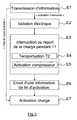
- FIG. figure 2 A first embodiment of the charge management method according to the invention is represented in FIG. figure 2 , in the form of an algorithm comprising steps E1 to E7.
- the charge management method according to the invention is implemented for the most part in the DPC device for controlling the compressor COMP. It limits the leakage currents due to the compressor COMP during a charge of the battery BATT, evacuating most of the liquid contained in the compressor COMP before this charging or stopping charging before starting compressor COMP. The value of the parasitic capacitance CP is thus greatly reduced when the battery BATT is charging.
- the first step E1 is the transmission, by the DPC device for controlling the compressor COMP, of information representative of a state of the compressor COMP to the charge management device DGC. If this information is representative of an advanced start-up of the compressor COMP, then the charge management device DGC activates the charging of the battery BATT according to the step E7, the parasitic capacitance CP of the compressor COMP being already relatively low. On the contrary, if this information is representative of an imminent activation, or having a duration shorter than a specified duration, of the compressor COMP, then the next step is the step E2.
- Step E2 is the electrical isolation between the compressor COMP and the network RES. This electrical insulation is effected by opening the contactors C between the charging device DC and the network RES. As a variant, it is effected by the opening of contactors between the battery BATT and the charging device DC, or by the opening of the switches of a rectifier or inverter stage of the charging device DC.
- control device DPC of the compressor COMP sends information representative of an advanced state of activation of the compressor COMP to the charge management device DGC according to a step E6 of the charge management method according to the invention.
- the DGC load management device Upon receipt of this information indicative of an advanced state of activation of the compressor COMP, the DGC load management device activates or reactivates the charging of the battery BATT according to step E7. For this, the contactors C are closed again.
- the first predetermined duration T1 is between approximately 2 and 15 seconds. It is calculated so that the majority of the possible liquid present in the compressor COMP is removed from the compressor COMP, thus significantly reducing the parasitic capacitance CP of the compressor COMP. This calculation is performed for example dynamically by the DPC device for controlling the compressor COMP as a function of the temperature outside the vehicle VE and / or the current speed of the compressor COMP, that is to say its speed range.
- the DPC device for controlling the compressor COMP determines the first predetermined duration T1 as a function only of the outside temperature, but does not increment the counter allowing the duration T1 to flow until the compressor COMP has reached a predetermined minimum speed. depending on the outside temperature. So the first predetermined duration T1 is incremented by a time necessary to reach a speed of the compressor COMP without using tables or calculations, while interrupting or deferring the charge of the battery BATT as short as possible.
- the DPC device for controlling the compressor COMP possibly imposes a minimum speed on the motor of the compressor COMP to limit the duration of interruption or load transfer of the battery BATT. This constraint is for example imposed on the compressor COMP when the state of the compressor COMP and the outside temperature allow it.
- the DPC control device of the compressor COMP interrupts the charging of the battery BATT when it starts up, it can happen, for example if it overheats or following a need for cycles of activation / deactivation of the compressor controlled by the SRT thermal control system, to require several interruptions of charge during the request for thermal regulation.
- the DPC control device of the compressor COMP stops the compressor COMP after a predetermined number of load interruptions, for example two, due to the compressor COMP, to allow the charging of the battery BATT to proceed without interruption.
- FIG. figure 3 A second embodiment of the charge management method according to the invention is shown in FIG. figure 3 , in the form of an algorithm comprising steps A1 to A6.
- the charge management method according to the invention is implemented for the most part in the DGC device for charge management, according to the same strategy of partial emptying of the compressor COMP before or during a charge of the battery BATT. than in the first embodiment of the invention.
- the DGC load management device systematically interrogates the control device DPC of the compressor COMP before activating the battery charge BATT. It is therefore assumed, prior to the first step A1 of the load management method according to the invention, that the DGC load management device is about to activate a load of the traction battery BATT.
- the DGC load management device does not routinely interrogate the compressor control device DPC, and itself supervises its interruption for a first predetermined duration T1.
- the charge management method according to the invention begins with step A2 described below.
- Step A1 is the interrogation, by the DGC load management device, of the compressor control device DPC, on the state of the compressor COMP.
- the next step A2 is the transmission, by the device DPC of the control of the compressor COMP, to the device DGC of charge management, information on the state of the compressor COMP. If this information is representative of an advanced start-up of the compressor COMP, then the DGC load management device activates the charging of the battery BATT according to step A6, the parasitic capacitance CP of the compressor COMP being already relatively low. On the contrary, if this information is representative of an imminent activation, or having a duration shorter than a specified duration, of the compressor COMP, then the next step is step A3.
- Step A3 is the electrical isolation between the compressor COMP and the network RES. This electrical insulation is performed in the same way as in step E2, by opening contactors, or switches DC charging device.
- the next step A4 is the transfer of the charge of the battery BATT by the charge management device DGC for at least a first predetermined duration T1.
- This first predetermined duration T1 is supervised by the charge management device DGC, which implements during this step A4, a substep A5 of activation of the compressor COMP, by sending an activation message to the device DPC for controlling the compressor COMP.
- the first predetermined duration T1 must allow the majority of the possible liquid present in the compressor COMP to be evacuated from the compressor COMP, thus significantly reducing the parasitic capacitance CP of the compressor COMP. It is for example obtained by the DGC load management device by tables providing a predetermined first time value T1 as a function of the outside temperature.
- the next step A6 is the activation of the charge of the battery BATT, after the first predetermined duration T1.
- the charge management method according to the invention is implemented for the most part in the DGC device for load management, according to a strategy of stopping and electrically isolating the compressor COMP systematically during a charging operation.
- the BATT battery of the VE vehicle the BATT battery of the VE vehicle.
- Step B1 is the transmission, by the DGC device for charge management, of information representative of an imminent charge of the BATT battery, to the DPC device for controlling the compressor COMP.
- Step B2 is the electrical insulation of the COMP compressor with respect to the DC charging device. This insulation is performed for example by opening the switches of an inverter stage of the ECP control electronics COMP compressor.
- Step B3 is the inhibition of the control of compressor COMP.
- the DGC charge management device warns the COMP compressor control DPC device of the end of the charge to enable it to reactivate the compressor COMP if necessary.
Landscapes
- Engineering & Computer Science (AREA)
- Mechanical Engineering (AREA)
- Transportation (AREA)
- Power Engineering (AREA)
- Chemical & Material Sciences (AREA)
- Sustainable Development (AREA)
- Life Sciences & Earth Sciences (AREA)
- Sustainable Energy (AREA)
- Chemical Kinetics & Catalysis (AREA)
- Electrochemistry (AREA)
- General Chemical & Material Sciences (AREA)
- Manufacturing & Machinery (AREA)
- Thermal Sciences (AREA)
- Combustion & Propulsion (AREA)
- Physics & Mathematics (AREA)
- Automation & Control Theory (AREA)
- Charge And Discharge Circuits For Batteries Or The Like (AREA)
- Electric Propulsion And Braking For Vehicles (AREA)
- Control Of Positive-Displacement Pumps (AREA)
- Air-Conditioning For Vehicles (AREA)
Description
- La présente invention se rapporte de manière générale aux domaines de l'automobile et de l'électrotechnique, et concerne plus précisément un procédé de gestion de la charge électrique d'un véhicule comportant une batterie de traction rechargeable. Ce véhicule est donc un véhicule à propulsion électrique ou hybride.
- Un tel véhicule est parfois pourvu d'un chargeur de batterie non isolé, susceptible de faire circuler lors de la charge de la batterie, des courants de fuite qui circulent vers la terre. Or une partie de ces courants de fuite peut être absorbée par une personne touchant la carrosserie du véhicule, qui est alors traversée par un courant de toucher, d'autant plus important que la prise de terre du chargeur est mauvaise, c'est-à-dire que la résistance de terre est importante.
- Il est donc souhaitable de diminuer autant que possible ces courants de fuite, dont une partie est générée par les consommateurs du réseau électrique du véhicule. Notamment, lorsque celui-ci est pourvu d'un système de régulation thermique, le compresseur d'un tel système est susceptible de générer lors de son fonctionnement, des courants de fuite vers la terre.
- On appelle ici système de régulation thermique tout système permettant de modifier la température d'un organe du véhicule, qu'il s'agisse d'un système de pompe à chaleur permettant de réchauffer l'habitacle du véhicule, d'un système de climatisation ou d'une boucle de régulation thermodynamique permettant de réguler la température de la batterie.
- Les courants de fuite générés par le compresseur du système de régulation thermique du véhicule sont d'autant plus importants lorsqu'une charge du véhicule est enclenchée, car les tensions du réseau d'alimentation rechargeant la batterie de traction du véhicule augmentent l'intensité des courants de fuite pouvant transiter dans les capacités de mode commun des différents consommateurs électriques en aval du chargeur. De plus les courants de fuite générés par le compresseur du système de régulation thermique ont une fréquence due à l'électronique de pilotage du compresseur et une intensité telles qu'ils sont susceptibles d'aveugler les mécanismes de protection différentiels mis en oeuvre usuellement lors de la charge du véhicule.
- Habituellement, les risques électriques dus au compresseur d'un véhicule sont résolus en améliorant la qualité de la prise de terre du compresseur. C'est le cas par exemple de la demande de brevet japonais
JP07132725 - On sait également limiter les courants de fuite dus au compresseur d'un système de régulation thermique, en ajoutant des composants électroniques à l'électronique de pilotage du compresseur, comme proposé par exemple dans la demande de brevet japonais
JP01243843 - Un des buts de l'invention est de remédier à au moins une partie des inconvénients de la technique antérieure en fournissant un procédé de gestion de charge d'une batterie de traction d'un véhicule et des dispositifs associés permettant de recharger électriquement le véhicule en minimisant les risques électriques dus notamment aux courants de fuite du système de régulation thermique du véhicule.
- A cette fin, l'invention propose un procédé de gestion de charge d'une batterie de traction d'un véhicule comportant un système de régulation thermique, ledit système de régulation thermique comportant un compresseur, ledit procédé étant caractérisé en ce qu'il comporte une étape de transmission d'information entre un dispositif de pilotage du compresseur et un dispositif de gestion de charge de ladite batterie de traction, avant une étape d'activation du compresseur ou avant une étape d'activation d'un dispositif de charge de ladite batterie de traction.
- Grâce à l'invention, le dispositif de gestion de charge ou le dispositif de pilotage du compresseur sont en mesure de tenir compte d'une prochaine étape de charge du véhicule ou d'une prochaine étape d'activation du compresseur, pour limiter les courants de fuite en adoptant une stratégie adéquate. Cette stratégie consiste par exemple en :
- l'isolation électrique du compresseur lors de la charge du véhicule, le compresseur étant alors inhibé,
- ou la temporisation de la charge du véhicule le temps que le compresseur ne soit plus rempli de liquide ce qui permet de diminuer les courants de fuite dus au compresseur.
- Selon une caractéristique avantageuse du procédé de gestion de charge selon l'invention, ladite étape de transmission d'information correspond à une étape d'envoi par ledit dispositif de pilotage du compresseur, d'une information représentative d'un état du compresseur, audit dispositif de gestion de charge de la batterie de traction.
- La connaissance par le dispositif de gestion de charge de l'état du compresseur lui permet de déterminer quand commencer une recharge électrique du véhicule en minimisant les risques électriques et ainsi de choisir la stratégie optimale de limitation des courants de fuite.
- Selon une autre caractéristique avantageuse, le procédé de gestion de charge selon l'invention comporte en outre une étape d'isolation électrique entre ledit compresseur et un réseau d'alimentation extérieur destiné à charger ladite batterie de traction, lorsque ladite information est représentative d'une activation imminente dudit compresseur.
- Selon une autre caractéristique avantageuse, le procédé de gestion de charge selon l'invention comporte en outre une étape d'interruption ou de report d'une charge de ladite batterie de traction pendant au moins une première durée prédéterminée, lorsque ladite information est représentative d'une activation imminente dudit compresseur.
- Le fait de rendre ainsi l'activation du compresseur prioritaire par rapport à la charge électrique du véhicule est avantageux car la mise en route du compresseur est beaucoup plus rapide que la charge complète d'une batterie de traction. De plus la batterie de traction nécessite en général d'être chauffée ou refroidie par un système de régulation thermique pour être rechargée, et donc la charge du véhicule nécessite souvent la mise en route d'un compresseur.
- Selon une autre caractéristique avantageuse, ladite première durée prédéterminée est fonction de la température extérieure et/ou du régime courant du compresseur.
- L'interruption ou le report de la charge du véhicule est ainsi limitée au plus près à la durée nécessaire à l'évacuation de la majeure partie du liquide contenu dans le compresseur durant sa mise en route.
- Selon une autre caractéristique avantageuse, ladite première durée prédéterminée est incrémentée d'une durée nécessaire à l'atteinte d'une vitesse minimum prédéterminée fonction de la température extérieure, par le moteur dudit compresseur.
- Cette incrémentation permet d'utiliser un régime compresseur au moins égal à un régime en-dessous duquel l'évacuation du liquide n'est pas considérée comme réalisable, ce suivant la température extérieure.
- Selon une caractéristique avantageuse de l'invention, lorsque ledit compresseur nécessite plusieurs étapes d'activation pour répondre à un besoin du système de régulation thermique, la charge de ladite batterie de traction est ininterrompue après un nombre prédéterminé d'étapes d'activation dudit compresseur.
- Cette caractéristique supplémentaire permet, lorsque l'étape d'activation du compresseur est prioritaire sur l'étape d'activation du dispositif de charge du véhicule, de réduire le temps de charge du véhicule et d'éviter une charge saccadée qui nuirait aux composants du dispositif de charge, par exemple lorsque le compresseur présente un défaut de fonctionnement ou lorsque le système de régulation impose au compresseur de réaliser des cycles d'activations et de désactivations.
- Selon une autre caractéristique avantageuse, ledit dispositif de pilotage dudit compresseur impose une vitesse minimum au moteur dudit compresseur, cette vitesse minimum étant fonction de la température extérieure.
- Cette caractéristique supplémentaire permet encore de réduire le temps de charge du véhicule même lorsque l'étape d'activation du compresseur est prioritaire sur l'étape d'activation du dispositif de charge du véhicule.
- Selon une autre caractéristique avantageuse, ladite étape de transmission d'information est suivie d'une étape de temporisation de l'étape d'activation du compresseur pendant une seconde durée prédéterminée, inférieure à ladite première durée prédéterminée, et ledit dispositif de pilotage du compresseur envoie une information représentative d'un état avancé d'activation du compresseur à l'issue de ladite première durée prédéterminée.
- Cette caractéristique supplémentaire permet l'implémentation de la logique du procédé de gestion de charge selon l'invention dans le dispositif de pilotage du compresseur, ce qui permet de mieux maîtriser les contraintes dues à la commande du compresseur, qui varient notamment en fonction de la température extérieure, de son état précédent, etc.
- Selon une variante de réalisation de l'invention, ladite étape de transmission d'information est précédée d'une étape d'interrogation sur l'état du compresseur par ledit dispositif de gestion de charge, et ladite première durée prédéterminée est supervisée par ledit dispositif de gestion de charge.
- Selon cette variante, la logique du procédé de gestion de charge selon l'invention est implémentée dans le dispositif de gestion de charge, ce qui permet de gérer plus facilement la charge du véhicule. En effet dans cette variante le dispositif de gestion de charge communique avec le dispositif de pilotage du compresseur selon un modèle requête/réponse ce qui permet de ne pas gérer de processus logique supplémentaire.
- Selon une variante de réalisation de l'invention, ladite étape d'isolation est suivie d'une étape d'inhibition du compresseur jusqu'à la fin d'une étape de charge de la batterie de traction.
- Dans cette alternative, l'étape d'activation du dispositif de charge est prioritaire par rapport à l'étape d'activation du compresseur, celui-ci étant isolé électriquement du dispositif de charge pour réduire les courants de fuite dus au compresseur.
- L'invention concerne aussi un dispositif de gestion de charge caractérisé en ce qu'il comporte des moyens pour mettre en oeuvre le procédé de gestion de charge selon l'invention.
- L'invention concerne encore un dispositif de pilotage d'un compresseur, caractérisé en ce qu'il comporte des moyens pour mettre en oeuvre le procédé de gestion de charge selon l'invention.
- L'invention concerne enfin un programme d'ordinateur comportant des instructions pour mettre en oeuvre le procédé de gestion de charge selon l'invention, lorsqu'il est exécuté sur un ou plusieurs processeurs.
- Le dispositif de gestion de charge selon l'invention, le dispositif de pilotage d'un compresseur selon l'invention ainsi que le programme d'ordinateur présentent des avantages analogues à ceux du procédé de gestion de charge selon l'invention.
- D'autres caractéristiques et avantages apparaîtront à la lecture de modes de réalisation préférés décrits en référence aux figures dans lesquelles :
- la
figure 1 représente un véhicule comportant un dispositif de gestion de charge et un dispositif de pilotage d'un compresseur selon l'invention, - la
figure 2 représente des étapes du procédé de gestion de charge selon l'invention, dans un premier mode de réalisation de l'invention, - la
figure 3 représente des étapes du procédé de gestion de charge selon l'invention, dans un deuxième mode de réalisation de l'invention, - et la
figure 4 représente des étapes du procédé de gestion de charge selon l'invention, dans un troisième mode de réalisation de l'invention. - Selon un mode préféré de réalisation de l'invention représenté à la
figure 1 , un véhicule VE électrique ou hybride comporte une batterie de traction BATT, rechargeable via un dispositif de charge DC, par un réseau d'alimentation électrique RES extérieur. Le dispositif de charge DC comporte des moyens de connexion à une ligne de phase P et à une ligne neutre N du réseau RES, ces moyens de connexion étant munis de contacteurs C permettant d'isoler électriquement le réseau RES et le dispositif de charge DC. - Dans cet exemple d'utilisation de l'invention, le réseau RES est un réseau monophasé, mais le dispositif de charge DC comporte également des moyens de recharge de la batterie BATT par un réseau d'alimentation triphasé ou par un réseau d'alimentation continue.
- Le dispositif de charge DC est connecté au réseau haute tension du véhicule VE. Plus précisément les bornes de sortie du dispositif de charge DC sont connectées d'une part à un bus BP lui-même connecté à la borne positive de la batterie BATT, et d'autre part à un bus BN lui-même connecté à la borne négative de la batterie BATT.
- Le véhicule VE comporte également un système de régulation thermique SRT comportant lui-même un compresseur COMP. Le moteur du compresseur COMP comporte des bobinages statoriques alimentés par la batterie BATT via une électronique ECP de pilotage du compresseur COMP. L'électronique ECP de pilotage du compresseur COMP est connectée en entrée aux bus BP et BN de la batterie BATT et en sortie aux bobinages statoriques du compresseur COMP.
- Lorsque le compresseur COMP est activé, l'électronique ECP de pilotage du compresseur COMP génère des impulsions de commande sur les bobinages statoriques du compresseur COMP, qui sont alors alimentés par un courant triphasé d'une certaine fréquence et d'une certaine intensité. Or les bobinages statoriques du compresseur COMP présentent une capacité parasite CP de couplage au châssis du véhicule VE. Cette capacité parasite CP est donc traversée, lorsque le compresseur COMP est activé, par un courant de fuite dépendant de la fréquence de découpage de l'électronique ECP et de la valeur de la capacité parasite CP. Ce courant de fuite se déverse normalement vers la terre T par le chemin représenté par les flèches noires sur la
figure 1 . - Or la capacité parasite CP est typiquement de quelques nanofarads, et peut augmenter de plusieurs dizaines de nanofarads lorsque du fluide du système de régulation thermique SRT est concentré à l'état liquide dans le compresseur COMP, ce qui peut être le cas lorsque celui-ci est au repos depuis longtemps. En effet, comme les bobinages statoriques du compresseur COMP sont plongés dans un mélange d'huile et de réfrigérant, la capacité parasite CP varie en grande partie selon le mode de fonctionnement du compresseur, selon la température extérieure et par exemple la quantité d'eau dans le fluide.
- Lorsque le compresseur COMP est activé après avoir été longtemps au repos, par exemple pour pré-conditionner l'habitacle du véhicule VE, ou dégivrer la face avant du véhicule, ou encore pour pré-conditionner la batterie BATT en vue de la recharger, et lorsque la charge de la batterie BATT est activée, le courant de fuite dû au compresseur COMP peut reboucler par le réseau d'alimentation RES, si la prise de terre T est défectueuse. Dans ce cas ce courant de fuite est susceptible d'aveugler des dispositifs de protection de la charge du véhicule VE, empêchant la coupure de l'alimentation du dispositif de charge DC même en cas de courant de toucher. Ceci est dû notamment à l'intensité et à la fréquence de ce courant de fuite, non détectées par les mécanismes de protection différentiels usuels.
- Le procédé de gestion de charge selon l'invention permet de diminuer les courants de fuite dus au compresseur COMP pendant la charge du véhicule VE, en mettant en oeuvre une ou plusieurs stratégies de charge, implémentées au moins en partie dans un dispositif de gestion de charge DGC selon l'invention et/ou dans un dispositif selon l'invention de pilotage DPC du compresseur COMP. Le dispositif de gestion de charge DGC et le dispositif de pilotage DPC du compresseur COMP communiquent grâce au bus de communication CAN (d'après l'anglais «Controller Area Network ») du véhicule VE. Ces deux dispositifs sont interfacés également à d'autres actionneurs ou calculateurs du véhicule VE par ce bus CAN.
- Le dispositif de pilotage DPC du compresseur est réparti entre plusieurs calculateurs dont un calculateur de gestion de la climatisation, un calculateur de gestion de la requête de vitesse du compresseur en fonction des besoins du calculateur de gestion de la climatisation, et la partie actionneur électromécanique ainsi que la carte électronique intégrée du compresseur COMP lui-même. Le dispositif de pilotage DPC du compresseur est donc à la fois électronique et logiciel.
- Un premier mode de réalisation du procédé de gestion de charge selon l'invention est représenté à la
figure 2 , sous forme d'un algorithme comportant des étapes E1 à E7. - Dans ce premier mode de réalisation, le procédé de gestion de charge selon l'invention est implémenté en majeure partie dans le dispositif DPC de pilotage du compresseur COMP. Il limite les courants de fuite dus au compresseur COMP pendant une charge de la batterie BATT, en évacuant la majeure partie du liquide contenu dans le compresseur COMP avant cette charge ou en interrompant la charge avant de mettre en route le compresseur COMP. La valeur de la capacité parasite CP se trouve ainsi fortement diminuée lorsque la batterie BATT est en charge.
- On suppose donc, dans ce premier mode de réalisation, qu'une demande d'activation du dispositif de charge DC, envoyée par le dispositif de gestion de charge DGC, ou une demande d'activation du compresseur COMP envoyée par un calculateur du système de régulation thermique SRT, est reçue par le dispositif DPC de pilotage du compresseur COMP, déclenchant le procédé de gestion de charge selon l'invention.
- La première étape E1 est la transmission, par le dispositif DPC de pilotage du compresseur COMP, d'une information représentative d'un état du compresseur COMP au dispositif de gestion de charge DGC. Si cette information est représentative d'une mise en route avancée du compresseur COMP, alors le dispositif de gestion de charge DGC active la charge de la batterie BATT selon l'étape E7, la capacité parasite CP du compresseur COMP étant déjà relativement faible. Au contraire si cette information est représentative d'une activation imminente, ou ayant une durée inférieure à une durée spécifiée, du compresseur COMP, alors l'étape suivante est l'étape E2.
- L'étape E2 est l'isolation électrique entre le compresseur COMP et le réseau RES. Cette isolation électrique s'effectue par l'ouverture des contacteurs C entre le dispositif de charge DC et le réseau RES. En variante, il s'effectue par l'ouverture de contacteurs entre la batterie BATT et le dispositif de charge DC, ou encore par l'ouverture des interrupteurs d'un étage redresseur ou onduleur du dispositif de charge DC.
- L'étape suivante E3 est l'interruption ou le report de la charge de la batterie BATT, par le dispositif de gestion de charge DGC, pendant au moins une première durée prédéterminée T1. Cette première durée prédéterminée T1 est supervisée par le dispositif DPC de pilotage du compresseur COMP, qui met en oeuvre deux sous-étapes pendant cette étape E3 :
- Dans une première sous-étape E4, le dispositif DPC de pilotage du compresseur COMP temporise l'activation du compresseur COMP pendant une deuxième durée prédéterminée T2 d'environ 500 millisecondes permettant au dispositif de gestion de charge DGC de recevoir l'information transmise lors de l'étape E1 et d'interrompre un processus de charge si la batterie BATT était déjà en charge.
- Dans une deuxième sous-étape E5, le dispositif DPC de pilotage du compresseur COMP active le compresseur COMP.
- A la fin de la première durée prédéterminée T1, le dispositif DPC de pilotage du compresseur COMP envoie une information représentative d'un état avancé d'activation du compresseur COMP au dispositif de gestion de charge DGC selon une étape E6 du procédé de gestion de charge selon l'invention.
- A la réception de cette information représentative d'un état avancé d'activation du compresseur COMP, le dispositif de gestion de charge DGC active ou réactive la charge de la batterie BATT selon l'étape E7. Pour cela les contacteurs C sont refermés.
- La première durée prédéterminée T1 vaut entre 2 et 15 secondes approximativement. Elle est calculée de sorte que la majorité de l'éventuel liquide présent dans le compresseur COMP soit évacuée du compresseur COMP, diminuant ainsi significativement la capacité parasite CP du compresseur COMP. Ce calcul est effectué par exemple dynamiquement par le dispositif DPC de pilotage du compresseur COMP en fonction de la température extérieure au véhicule VE et/ou du régime courant du compresseur COMP, c'est-à-dire sa plage de vitesse. En variante le dispositif DPC de pilotage du compresseur COMP détermine la première durée prédéterminée T1 en fonction seulement de la température extérieure, mais n'incrémente le compteur permettant de faire s'écouler la durée T1 que lorsque le compresseur COMP a atteint une vitesse minimum prédéterminée fonction de la température extérieure. Ainsi la première durée prédéterminée T1 est incrémentée d'une durée nécessaire à l'atteinte d'un régime du compresseur COMP sans recourir à des tables ou calculs, tout en interrompant ou en différant la charge de la batterie BATT le moins longtemps possible.
- Le dispositif DPC de pilotage du compresseur COMP impose éventuellement une vitesse minimum au moteur du compresseur COMP pour limiter la durée d'interruption ou de report de charge de la batterie BATT. Cette contrainte est par exemple imposée au compresseur COMP quand l'état du compresseur COMP et la température extérieure le permettent.
- Le dispositif de pilotage DPC du compresseur COMP interrompant la charge de la batterie BATT lorsque celui-ci se met en route, il peut arriver, par exemple s'il surchauffe ou suivant un besoin de cycles d' activation/désactivation du compresseur commandé par le système de régulation thermique SRT , de nécessiter plusieurs interruptions de charge durant la demande de régulation thermique. Dans ce cas le dispositif de pilotage DPC du compresseur COMP arrête le compresseur COMP au bout d'un nombre prédéterminé d'interruptions de charge, par exemple deux, dues au compresseur COMP, pour laisser la charge de la batterie BATT se dérouler sans interruption.
- Un deuxième mode de réalisation du procédé de gestion de charge selon l'invention est représenté à la
figure 3 , sous forme d'un algorithme comportant des étapes A1 à A6. - Dans ce deuxième mode de réalisation, le procédé de gestion de charge selon l'invention est implémenté en majeure partie dans le dispositif DGC de gestion de charge, selon la même stratégie de vidange partielle du compresseur COMP avant ou durant une charge de la batterie BATT que dans le premier mode de réalisation de l'invention.
- Dans ce deuxième mode de réalisation, le dispositif de gestion de charge DGC interroge systématiquement le dispositif DPC de pilotage du compresseur COMP avant d'activer la charge de la batterie BATT. On suppose donc, préalablement à la première étape A1 du procédé de gestion de charge selon l'invention, que le dispositif de gestion de charge DGC s'apprête à activer une charge de la batterie BATT de traction. En variante, le dispositif de gestion de charge DGC n'interroge pas systématiquement le dispositif DPC de pilotage du compresseur, et supervise lui-même son interruption pendant une première durée prédéterminée T1. Dans cette variante le procédé de gestion de charge selon l'invention commence par l'étape A2 décrite ci-après.
- L'étape A1, selon la variante principale de ce deuxième mode de réalisation de l'invention, est l'interrogation, par le dispositif de gestion de charge DGC, du dispositif DPC de pilotage du compresseur, sur l'état du compresseur COMP.
- L'étape suivante A2 est la transmission, par le dispositif DPC du pilotage du compresseur COMP, au dispositif DGC de gestion de charge, d'une information sur l'état du compresseur COMP. Si cette information est représentative d'une mise en route avancée du compresseur COMP, alors le dispositif de gestion de charge DGC active la charge de la batterie BATT selon l'étape A6, la capacité parasite CP du compresseur COMP étant déjà relativement faible. Au contraire si cette information est représentative d'une activation imminente, ou ayant une durée inférieure à une durée spécifiée, du compresseur COMP, alors l'étape suivante est l'étape A3.
- L'étape A3 est l'isolation électrique entre le compresseur COMP et le réseau RES. Cette isolation électrique s'effectue de la même façon qu'à l'étape E2, par ouverture de contacteurs, ou d'interrupteurs du dispositif de charge DC.
- L'étape suivante A4 est le report de la charge de la batterie BATT, par le dispositif de gestion de charge DGC, pendant au moins une première durée prédéterminée T1. Cette première durée prédéterminée T1 est supervisée par le dispositif de gestion de charge DGC, qui met en oeuvre pendant cette étape A4, une sous-étape A5 d'activation du compresseur COMP, par envoi d'un message d'activation au dispositif DPC de pilotage du compresseur COMP. La première durée prédéterminée T1 doit permettre à la majorité de l'éventuel liquide présent dans le compresseur COMP d'être évacuée du compresseur COMP, diminuant ainsi significativement la capacité parasite CP du compresseur COMP. Elle est par exemple obtenue par le dispositif de gestion de charge DGC par des tables fournissant une valeur de première durée prédéterminée T1 en fonction de la température extérieure.
- L'étape suivante A6 est l'activation de la charge de la batterie BATT, à l'issue de la première durée prédéterminée T1.
- Un troisième mode de réalisation du procédé de gestion de charge selon l'invention est représenté à la
figure 4 , sous forme d'un algorithme comportant des étapes B1 à B4. - Dans ce troisième mode de réalisation, le procédé de gestion de charge selon l'invention est implémenté en majeure partie dans le dispositif DGC de gestion de charge, selon une stratégie d'arrêt et d'isolation électrique du compresseur COMP systématiquement pendant une charge de la batterie BATT du véhicule VE. Ainsi on s'affranchit des courants de fuite dus au compresseur COMP pendant la charge de la batterie BATT.
- On suppose donc, préalablement à une première étape B1 du procédé de gestion charge selon l'invention, que le dispositif de gestion de charge DGC s'apprête à activer une charge de la batterie BATT de traction.
- L'étape B1 est la transmission, par le dispositif DGC de gestion de charge, d'une information représentative d'une charge imminente de la batterie BATT, au dispositif DPC de pilotage du compresseur COMP.
- L'étape B2 est l'isolation électrique du compresseur COMP par rapport au dispositif DC de charge. Cette isolation est effectuée par exemple par l'ouverture des interrupteurs d'un étage onduleur de l'électronique ECP de pilotage du compresseur COMP.
- L'étape B3 est l'inhibition du pilotage du compresseur COMP.
- Enfin l'étape B4 est l'activation de la charge de la batterie BATT, par fermeture des contacteurs C notamment. Pendant toute cette étape B4, le compresseur COMP est arrêté privant le véhicule VE des prestations thermiques. Ce troisième mode de réalisation de l'invention, plus radical que les deux premiers pour s'affranchir des courants de fuite dus au compresseur COMP, est donc envisageable seulement lorsque la charge de la batterie BATT peut s'effectuer sans pré-conditionnement de la batterie BATT.
- A la fin de l'étape B4, le dispositif DGC de gestion de charge avertit le dispositif DPC de pilotage du compresseur COMP de la fin de la charge pour lui permettre de réactiver le compresseur COMP si nécessaire.
- Il est à noter que ces modes de réalisation de l'invention ne sont pas exhaustifs, la communication entre le dispositif DGC de gestion de charge et le dispositif DPC de pilotage du compresseur COMP pouvant être plus ou moins limitée ou au contraire très élaborée. Ainsi l'information transmise lors de la première étape du procédé de gestion de charge selon l'invention est représentative, selon l'implémentation choisie du procédé de gestion de charge selon l'invention :
- d'une activation imminente du compresseur COMP,
- ou bien d'une activation du compresseur COMP ayant une durée inférieure à une durée spécifiée,
- ou bien d'un état avancé d'une activation du compresseur COMP si le dispositif DGC de gestion de charge n'autorise la charge de la batterie BATT qu'après réception d'une telle information,
- ou bien d'une activation imminente d'une charge de la batterie BATT,
- ou bien de la fin d'une charge de la batterie BATT, par exemple si le dispositif DPC de pilotage du compresseur COMP n'autorise l'activation du compresseur COMP qu'après réception d'une telle information.
Claims (14)
- Procédé de gestion de charge d'une batterie (BATT) de traction d'un véhicule (VE) comportant un système de régulation thermique (SRT), ledit système de régulation thermique (SRT) comportant un compresseur (COMP), ledit procédé étant caractérisé en ce qu'il comporte une étape (E1, A2, B1) de transmission d'information entre un dispositif (DPC) de pilotage du compresseur et un dispositif (DGC) de gestion de charge de ladite batterie (BATT) de traction, avant une étape (E5, A5) d'activation du compresseur (COMP) ou avant une étape d'activation (B4) d'un dispositif (DC) de charge de ladite batterie (BATT) de traction.
- Procédé de gestion de charge selon la revendication 1, caractérisé en ce que ladite étape (E1, A2) de transmission d'information correspond à une étape d'envoi par ledit dispositif (DPC) de pilotage du compresseur, d'une information représentative d'un état du compresseur (COMP), audit dispositif (DGC) de gestion de charge de la batterie (BATT) de traction.
- Procédé de gestion de charge selon la revendication 1 ou 2, caractérisé en ce qu'il comporte en outre une étape (E2, A3, B2) d'isolation électrique entre ledit compresseur (COMP) et un réseau d'alimentation extérieur destiné à charger ladite batterie de traction, lorsque ladite information est représentative d'une activation imminente dudit compresseur (COMP).
- Procédé de gestion de charge selon la revendication 2 ou 3, caractérisé en ce qu'il comporte en outre une étape (E3, A4) d'interruption ou de report d'une charge de ladite batterie (BATT) de traction pendant au moins une première durée prédéterminée (T1), lorsque ladite information est représentative d'une activation imminente dudit compresseur (COMP).
- Procédé de gestion de charge selon la revendication 4, caractérisé en ce que ladite première durée prédéterminée (T1) est fonction de la température extérieure et/ou du régime courant du compresseur (COMP).
- Procédé de gestion de charge selon la revendication 4, caractérisé en ce que ladite première durée prédéterminée (T1) est incrémentée d'une durée nécessaire à l'atteinte d'une vitesse minimum prédéterminée fonction de la température extérieure, par le moteur dudit compresseur (COMP).
- Procédé de gestion de charge selon l'une quelconque des revendications 4 à 6, caractérisé en ce que lorsque ledit compresseur (COMP) nécessite plusieurs étapes d'activation pour répondre à un besoin du système de régulation thermique (SRT), la charge de ladite batterie (BATT) de traction est ininterrompue après un nombre prédéterminé d'étapes d'activation dudit compresseur (COMP).
- Procédé de gestion de charge selon l'une quelconque des revendications 4 à 7, caractérisé en ce que ledit dispositif (DPC) de pilotage dudit compresseur impose une vitesse minimum au moteur dudit compresseur (COMP), ladite vitesse minimum étant fonction de la température extérieure.
- Procédé de gestion de charge selon l'une quelconque des revendications 4 à 8, caractérisé en ce que et en ce que ladite étape (E3) de transmission d'information est suivie d'une étape (E4) de temporisation de l'étape (E5) d'activation du compresseur (COMP) pendant une seconde durée prédéterminée (T2), inférieure à ladite première durée prédéterminée (T1), et en ce que ledit dispositif (DPC) de pilotage du compresseur envoie une information représentative d'un état avancé d'activation du compresseur (COMP) à l'issue de ladite première durée prédéterminée (T1).
- Procédé de gestion de charge selon l'une quelconque des revendications 4 à 8, caractérisé en ce que ladite étape (A2) de transmission d'information est précédée d'une étape d'interrogation (A1) sur l'état du compresseur (COMP) par ledit dispositif (DGC) de gestion de charge, et en ce que ladite première durée prédéterminée (T1) est supervisée par ledit dispositif (DGC) de gestion de charge.
- Procédé de gestion de charge selon la revendication 3, caractérisé en ce que ladite étape (B2) d'isolation est suivie d'une étape (B3) d'inhibition du compresseur (COMP) jusqu'à la fin d'une étape (B4) de charge de la batterie (BATT) de traction.
- Dispositif (DGC) de gestion de charge caractérisé en ce qu'il comporte des moyens pour mettre eh oeuvre le procédé de gestion de charge selon la revendication 10 ou 11.
- Dispositif (DPC) de pilotage d'un compresseur, caractérisé en ce qu'il comporte des moyens pour mettre en oeuvre le procédé de gestion de charge selon la revendication 9.
- Programme d'ordinateur comportant des instructions pour mettre en oeuvre le procédé de gestion de charge selon l'une quelconque des revendications 1 à 11, lorsqu'il est exécuté sur un ou plusieurs processeurs.
Applications Claiming Priority (2)
| Application Number | Priority Date | Filing Date | Title |
|---|---|---|---|
| FR1253027A FR2988917B1 (fr) | 2012-04-03 | 2012-04-03 | Procede de gestion de charge d'une batterie de traction et dispositifs correspondants |
| PCT/FR2013/050507 WO2013150200A1 (fr) | 2012-04-03 | 2013-03-11 | Procédé de gestion de charge d'une batterie de traction et dispositifs correspondants |
Publications (2)
| Publication Number | Publication Date |
|---|---|
| EP2834876A1 EP2834876A1 (fr) | 2015-02-11 |
| EP2834876B1 true EP2834876B1 (fr) | 2016-03-09 |
Family
ID=48083476
Family Applications (1)
| Application Number | Title | Priority Date | Filing Date |
|---|---|---|---|
| EP13715296.3A Not-in-force EP2834876B1 (fr) | 2012-04-03 | 2013-03-11 | Procédé de gestion de charge d'une batterie de traction et dispositifs correspondants |
Country Status (5)
| Country | Link |
|---|---|
| US (1) | US9827859B2 (fr) |
| EP (1) | EP2834876B1 (fr) |
| ES (1) | ES2565672T3 (fr) |
| FR (1) | FR2988917B1 (fr) |
| WO (1) | WO2013150200A1 (fr) |
Families Citing this family (2)
| Publication number | Priority date | Publication date | Assignee | Title |
|---|---|---|---|---|
| JP6129701B2 (ja) * | 2013-09-20 | 2017-05-17 | 株式会社東芝 | 充電管理装置、充電管理システムおよび充電管理方法 |
| JP7600924B2 (ja) | 2021-08-04 | 2024-12-17 | トヨタ自動車株式会社 | 車載空調システム |
Family Cites Families (19)
| Publication number | Priority date | Publication date | Assignee | Title |
|---|---|---|---|---|
| JPH0817571B2 (ja) | 1988-03-25 | 1996-02-21 | 三菱電機株式会社 | 圧縮式冷却装置 |
| JPH07132725A (ja) * | 1993-11-12 | 1995-05-23 | Matsushita Electric Ind Co Ltd | 自動車用空調装置 |
| US5743099A (en) * | 1996-06-11 | 1998-04-28 | Kraynak; Francis | Energy saving HVAC control system |
| JP3729228B2 (ja) * | 1997-10-17 | 2005-12-21 | サンデン株式会社 | 電気自動車用空調装置の漏電防止制御装置 |
| US6725134B2 (en) * | 2002-03-28 | 2004-04-20 | General Electric Company | Control strategy for diesel engine auxiliary loads to reduce emissions during engine power level changes |
| US6988371B2 (en) * | 2004-05-25 | 2006-01-24 | General Motors Corporation | Automotive HVAC system and method of operating same utilizing evaporator freezing |
| JP4804839B2 (ja) | 2005-09-05 | 2011-11-02 | カルソニックカンセイ株式会社 | 車両用空調装置の制御システム |
| US20080087482A1 (en) * | 2006-10-13 | 2008-04-17 | Ford Global Technologies, Llc | Hybrid electric vehicle with motor driven charge air booster |
| US8442752B2 (en) * | 2009-04-23 | 2013-05-14 | Ford Global Technologies, Llc | Climate control head with fuel economy indicator |
| US20110266075A1 (en) * | 2010-04-28 | 2011-11-03 | Guzelimian Harry L | Energy Generation System for Electric, Hybrid and Conventional Vehicles |
| US8662226B2 (en) * | 2010-06-08 | 2014-03-04 | Ford Global Technologies, Llc | Apparatus for heating a vehicle cabin |
| FR2987889B1 (fr) * | 2012-03-08 | 2014-04-18 | Renault Sa | Procede de commande automatique destine au degivrage d'une pompe a chaleur pour vehicule |
| FR2992274B1 (fr) * | 2012-06-20 | 2016-03-11 | Renault Sas | Procede de recharge d'une batterie de vehicule hybride a l'arret |
| US20160229282A1 (en) * | 2013-02-09 | 2016-08-11 | Quantumscape Corporation | Thermal management system for vehicles with an electric powertrain |
| US9337680B2 (en) * | 2013-03-12 | 2016-05-10 | Ford Global Technologies, Llc | Method and system for controlling an electric vehicle while charging |
| DE102014203859A1 (de) * | 2013-04-18 | 2014-10-23 | Robert Bosch Gmbh | Verfahren zum Temperieren einer in einem Fahrzeug angeordneten Traktionsbatterie während eines Ladevorgangs an einer Ladestation und Ladestation zur Ausführung eines solchen Verfahrens |
| US9296310B2 (en) * | 2014-03-18 | 2016-03-29 | Ford Global Technologies, Llc | Traction battery thermal management system |
| DE102014209249A1 (de) * | 2014-05-15 | 2015-11-19 | Ford Global Technologies, Llc | Elektrisches Ladeverfahren für ein Fahrzeug und elektrische Fahrzeugladevorrichtung |
| US9751427B2 (en) * | 2014-09-03 | 2017-09-05 | Ford Global Technologies, Llc | Vehicle traction battery thermal conditioning |
-
2012
- 2012-04-03 FR FR1253027A patent/FR2988917B1/fr not_active Expired - Fee Related
-
2013
- 2013-03-11 ES ES13715296.3T patent/ES2565672T3/es active Active
- 2013-03-11 EP EP13715296.3A patent/EP2834876B1/fr not_active Not-in-force
- 2013-03-11 US US14/390,491 patent/US9827859B2/en not_active Expired - Fee Related
- 2013-03-11 WO PCT/FR2013/050507 patent/WO2013150200A1/fr not_active Ceased
Also Published As
| Publication number | Publication date |
|---|---|
| WO2013150200A1 (fr) | 2013-10-10 |
| FR2988917A1 (fr) | 2013-10-04 |
| ES2565672T3 (es) | 2016-04-06 |
| FR2988917B1 (fr) | 2014-03-28 |
| US9827859B2 (en) | 2017-11-28 |
| EP2834876A1 (fr) | 2015-02-11 |
| US20150120112A1 (en) | 2015-04-30 |
Similar Documents
| Publication | Publication Date | Title |
|---|---|---|
| US12074433B2 (en) | Electric system and method for energizing the electric system | |
| EP2895356B1 (fr) | Systeme et procede de gestion de l'alimentation electrique d'au moins un equipement au redemarrage automatique d'un moteur thermique de vehicule | |
| US9365210B2 (en) | Method and arrangement in a hybrid vehicle | |
| FR2784517A1 (fr) | Circuit d'alimentation en energie pour un reseau de bord de vehicule automobile a deux branches d'alimentation de tensions differentes | |
| EP2915244B1 (fr) | Procede de transfert de charge et dispositif electrique associé | |
| FR2989945A1 (fr) | Reseau de bord de vehicule compose d'au moins deux parties | |
| EP3700053A1 (fr) | Système et procédé de précharge d'un condensateur par une batterie comportant une résistance de précharge et un dispositif hacheur | |
| EP2861450B1 (fr) | Procédé et système pour la mise en veille et le réveil d'un module de commande de véhicule automobile électrique | |
| EP2721713A2 (fr) | Procede pour alimenter un accessoire electrique d'un vehicule automobile comportant une batterie electrique a laquelle ledit accessoire est raccorde | |
| WO2013150200A1 (fr) | Procédé de gestion de charge d'une batterie de traction et dispositifs correspondants | |
| EP2941365B1 (fr) | Procede de gestion d'un systeme pour alimenter un reseau de bord d'un vehicle en energie electrique | |
| WO2012028797A2 (fr) | Vehicule automobile electrique equipe d'un chargeur avec ou sans contact | |
| EP3323668B1 (fr) | Système et procédé de commande d'alimentation électrique sans interruption domestique connectée à un véhicule électrique ou hybride | |
| EP2206232A2 (fr) | Système d'alimentation de machine électrique | |
| FR2966653A1 (fr) | Filtre de tension, commande | |
| FR2791481A1 (fr) | Dispositif de charge anticipee pour un accumulateur d'appoint pour un vehicule automobile | |
| EP3883125B1 (fr) | Circuit d'entraînement de traction et procédé de pilotage d'un tel circuit | |
| EP3020109B1 (fr) | Système de stabilisation d'une tension d'alimentation d'un réseau électrique de bord d'un véhicule automobile | |
| WO2016037685A1 (fr) | Procédé d'aide au démarrage d'un moteur thermique d'un véhicule automobile | |
| EP3016816A1 (fr) | Procede de commande d'un groupe motopropulseur electrique optimisant la phase d'utilisation a faible vitesse | |
| FR2992592A1 (fr) | Procede de commande d'une charge sans contact avec securisation des communications | |
| EP2529466A2 (fr) | Dispositif d'interface entre deux parties d'un reseau electrique | |
| CN119853560A (zh) | 电机控制方法、装置、设备及存储介质 | |
| WO2025191219A1 (fr) | Dispositif et procédé de protection lors de la décharge d'un condensateur | |
| CN119853559A (zh) | 电机控制方法、装置、设备及存储介质 |
Legal Events
| Date | Code | Title | Description |
|---|---|---|---|
| PUAI | Public reference made under article 153(3) epc to a published international application that has entered the european phase |
Free format text: ORIGINAL CODE: 0009012 |
|
| 17P | Request for examination filed |
Effective date: 20140617 |
|
| AK | Designated contracting states |
Kind code of ref document: A1 Designated state(s): AL AT BE BG CH CY CZ DE DK EE ES FI FR GB GR HR HU IE IS IT LI LT LU LV MC MK MT NL NO PL PT RO RS SE SI SK SM TR |
|
| AX | Request for extension of the european patent |
Extension state: BA ME |
|
| DAX | Request for extension of the european patent (deleted) | ||
| GRAP | Despatch of communication of intention to grant a patent |
Free format text: ORIGINAL CODE: EPIDOSNIGR1 |
|
| RIC1 | Information provided on ipc code assigned before grant |
Ipc: B60L 1/02 20060101ALI20150917BHEP Ipc: B60L 3/04 20060101ALI20150917BHEP Ipc: H01M 10/613 20140101ALI20150917BHEP Ipc: B60W 10/26 20060101ALI20150917BHEP Ipc: B60H 1/32 20060101ALI20150917BHEP Ipc: H01M 10/625 20140101ALI20150917BHEP Ipc: B60L 1/00 20060101ALI20150917BHEP Ipc: H01M 10/44 20060101AFI20150917BHEP Ipc: B60W 20/00 20060101ALI20150917BHEP Ipc: B60L 3/00 20060101ALI20150917BHEP Ipc: B60W 10/30 20060101ALI20150917BHEP Ipc: B60L 11/18 20060101ALI20150917BHEP Ipc: H01M 10/6569 20140101ALI20150917BHEP Ipc: B60H 1/00 20060101ALI20150917BHEP |
|
| INTG | Intention to grant announced |
Effective date: 20151013 |
|
| GRAS | Grant fee paid |
Free format text: ORIGINAL CODE: EPIDOSNIGR3 |
|
| GRAA | (expected) grant |
Free format text: ORIGINAL CODE: 0009210 |
|
| AK | Designated contracting states |
Kind code of ref document: B1 Designated state(s): AL AT BE BG CH CY CZ DE DK EE ES FI FR GB GR HR HU IE IS IT LI LT LU LV MC MK MT NL NO PL PT RO RS SE SI SK SM TR |
|
| REG | Reference to a national code |
Ref country code: GB Ref legal event code: FG4D Free format text: NOT ENGLISH |
|
| REG | Reference to a national code |
Ref country code: AT Ref legal event code: REF Ref document number: 780097 Country of ref document: AT Kind code of ref document: T Effective date: 20160315 Ref country code: CH Ref legal event code: EP |
|
| REG | Reference to a national code |
Ref country code: FR Ref legal event code: PLFP Year of fee payment: 4 |
|
| REG | Reference to a national code |
Ref country code: ES Ref legal event code: FG2A Ref document number: 2565672 Country of ref document: ES Kind code of ref document: T3 Effective date: 20160406 Ref country code: IE Ref legal event code: FG4D Free format text: LANGUAGE OF EP DOCUMENT: FRENCH |
|
| REG | Reference to a national code |
Ref country code: DE Ref legal event code: R096 Ref document number: 602013005399 Country of ref document: DE |
|
| REG | Reference to a national code |
Ref country code: LT Ref legal event code: MG4D |
|
| REG | Reference to a national code |
Ref country code: NL Ref legal event code: MP Effective date: 20160309 |
|
| REG | Reference to a national code |
Ref country code: NO Ref legal event code: T2 Effective date: 20160309 |
|
| PG25 | Lapsed in a contracting state [announced via postgrant information from national office to epo] |
Ref country code: HR Free format text: LAPSE BECAUSE OF FAILURE TO SUBMIT A TRANSLATION OF THE DESCRIPTION OR TO PAY THE FEE WITHIN THE PRESCRIBED TIME-LIMIT Effective date: 20160309 Ref country code: GR Free format text: LAPSE BECAUSE OF FAILURE TO SUBMIT A TRANSLATION OF THE DESCRIPTION OR TO PAY THE FEE WITHIN THE PRESCRIBED TIME-LIMIT Effective date: 20160610 Ref country code: FI Free format text: LAPSE BECAUSE OF FAILURE TO SUBMIT A TRANSLATION OF THE DESCRIPTION OR TO PAY THE FEE WITHIN THE PRESCRIBED TIME-LIMIT Effective date: 20160309 |
|
| REG | Reference to a national code |
Ref country code: AT Ref legal event code: MK05 Ref document number: 780097 Country of ref document: AT Kind code of ref document: T Effective date: 20160309 |
|
| PG25 | Lapsed in a contracting state [announced via postgrant information from national office to epo] |
Ref country code: SE Free format text: LAPSE BECAUSE OF FAILURE TO SUBMIT A TRANSLATION OF THE DESCRIPTION OR TO PAY THE FEE WITHIN THE PRESCRIBED TIME-LIMIT Effective date: 20160309 Ref country code: PL Free format text: LAPSE BECAUSE OF FAILURE TO SUBMIT A TRANSLATION OF THE DESCRIPTION OR TO PAY THE FEE WITHIN THE PRESCRIBED TIME-LIMIT Effective date: 20160309 Ref country code: NL Free format text: LAPSE BECAUSE OF FAILURE TO SUBMIT A TRANSLATION OF THE DESCRIPTION OR TO PAY THE FEE WITHIN THE PRESCRIBED TIME-LIMIT Effective date: 20160309 Ref country code: RS Free format text: LAPSE BECAUSE OF FAILURE TO SUBMIT A TRANSLATION OF THE DESCRIPTION OR TO PAY THE FEE WITHIN THE PRESCRIBED TIME-LIMIT Effective date: 20160309 Ref country code: LV Free format text: LAPSE BECAUSE OF FAILURE TO SUBMIT A TRANSLATION OF THE DESCRIPTION OR TO PAY THE FEE WITHIN THE PRESCRIBED TIME-LIMIT Effective date: 20160309 Ref country code: BE Free format text: LAPSE BECAUSE OF NON-PAYMENT OF DUE FEES Effective date: 20160331 Ref country code: LT Free format text: LAPSE BECAUSE OF FAILURE TO SUBMIT A TRANSLATION OF THE DESCRIPTION OR TO PAY THE FEE WITHIN THE PRESCRIBED TIME-LIMIT Effective date: 20160309 |
|
| PG25 | Lapsed in a contracting state [announced via postgrant information from national office to epo] |
Ref country code: EE Free format text: LAPSE BECAUSE OF FAILURE TO SUBMIT A TRANSLATION OF THE DESCRIPTION OR TO PAY THE FEE WITHIN THE PRESCRIBED TIME-LIMIT Effective date: 20160309 Ref country code: IS Free format text: LAPSE BECAUSE OF FAILURE TO SUBMIT A TRANSLATION OF THE DESCRIPTION OR TO PAY THE FEE WITHIN THE PRESCRIBED TIME-LIMIT Effective date: 20160709 |
|
| REG | Reference to a national code |
Ref country code: CH Ref legal event code: PL |
|
| PG25 | Lapsed in a contracting state [announced via postgrant information from national office to epo] |
Ref country code: CZ Free format text: LAPSE BECAUSE OF FAILURE TO SUBMIT A TRANSLATION OF THE DESCRIPTION OR TO PAY THE FEE WITHIN THE PRESCRIBED TIME-LIMIT Effective date: 20160309 Ref country code: RO Free format text: LAPSE BECAUSE OF FAILURE TO SUBMIT A TRANSLATION OF THE DESCRIPTION OR TO PAY THE FEE WITHIN THE PRESCRIBED TIME-LIMIT Effective date: 20160309 Ref country code: SM Free format text: LAPSE BECAUSE OF FAILURE TO SUBMIT A TRANSLATION OF THE DESCRIPTION OR TO PAY THE FEE WITHIN THE PRESCRIBED TIME-LIMIT Effective date: 20160309 Ref country code: AT Free format text: LAPSE BECAUSE OF FAILURE TO SUBMIT A TRANSLATION OF THE DESCRIPTION OR TO PAY THE FEE WITHIN THE PRESCRIBED TIME-LIMIT Effective date: 20160309 Ref country code: SK Free format text: LAPSE BECAUSE OF FAILURE TO SUBMIT A TRANSLATION OF THE DESCRIPTION OR TO PAY THE FEE WITHIN THE PRESCRIBED TIME-LIMIT Effective date: 20160309 Ref country code: PT Free format text: LAPSE BECAUSE OF FAILURE TO SUBMIT A TRANSLATION OF THE DESCRIPTION OR TO PAY THE FEE WITHIN THE PRESCRIBED TIME-LIMIT Effective date: 20160711 |
|
| REG | Reference to a national code |
Ref country code: DE Ref legal event code: R097 Ref document number: 602013005399 Country of ref document: DE |
|
| REG | Reference to a national code |
Ref country code: IE Ref legal event code: MM4A |
|
| PG25 | Lapsed in a contracting state [announced via postgrant information from national office to epo] |
Ref country code: IT Free format text: LAPSE BECAUSE OF FAILURE TO SUBMIT A TRANSLATION OF THE DESCRIPTION OR TO PAY THE FEE WITHIN THE PRESCRIBED TIME-LIMIT Effective date: 20160309 |
|
| PLBE | No opposition filed within time limit |
Free format text: ORIGINAL CODE: 0009261 |
|
| STAA | Information on the status of an ep patent application or granted ep patent |
Free format text: STATUS: NO OPPOSITION FILED WITHIN TIME LIMIT |
|
| PG25 | Lapsed in a contracting state [announced via postgrant information from national office to epo] |
Ref country code: DK Free format text: LAPSE BECAUSE OF FAILURE TO SUBMIT A TRANSLATION OF THE DESCRIPTION OR TO PAY THE FEE WITHIN THE PRESCRIBED TIME-LIMIT Effective date: 20160309 Ref country code: CH Free format text: LAPSE BECAUSE OF NON-PAYMENT OF DUE FEES Effective date: 20160331 Ref country code: LI Free format text: LAPSE BECAUSE OF NON-PAYMENT OF DUE FEES Effective date: 20160331 Ref country code: IE Free format text: LAPSE BECAUSE OF NON-PAYMENT OF DUE FEES Effective date: 20160311 |
|
| 26N | No opposition filed |
Effective date: 20161212 |
|
| PG25 | Lapsed in a contracting state [announced via postgrant information from national office to epo] |
Ref country code: BG Free format text: LAPSE BECAUSE OF FAILURE TO SUBMIT A TRANSLATION OF THE DESCRIPTION OR TO PAY THE FEE WITHIN THE PRESCRIBED TIME-LIMIT Effective date: 20160609 |
|
| REG | Reference to a national code |
Ref country code: FR Ref legal event code: PLFP Year of fee payment: 5 |
|
| PG25 | Lapsed in a contracting state [announced via postgrant information from national office to epo] |
Ref country code: SI Free format text: LAPSE BECAUSE OF FAILURE TO SUBMIT A TRANSLATION OF THE DESCRIPTION OR TO PAY THE FEE WITHIN THE PRESCRIBED TIME-LIMIT Effective date: 20160309 |
|
| PG25 | Lapsed in a contracting state [announced via postgrant information from national office to epo] |
Ref country code: MT Free format text: LAPSE BECAUSE OF FAILURE TO SUBMIT A TRANSLATION OF THE DESCRIPTION OR TO PAY THE FEE WITHIN THE PRESCRIBED TIME-LIMIT Effective date: 20160309 |
|
| REG | Reference to a national code |
Ref country code: FR Ref legal event code: PLFP Year of fee payment: 6 |
|
| PG25 | Lapsed in a contracting state [announced via postgrant information from national office to epo] |
Ref country code: HU Free format text: LAPSE BECAUSE OF FAILURE TO SUBMIT A TRANSLATION OF THE DESCRIPTION OR TO PAY THE FEE WITHIN THE PRESCRIBED TIME-LIMIT; INVALID AB INITIO Effective date: 20130311 |
|
| PG25 | Lapsed in a contracting state [announced via postgrant information from national office to epo] |
Ref country code: MK Free format text: LAPSE BECAUSE OF FAILURE TO SUBMIT A TRANSLATION OF THE DESCRIPTION OR TO PAY THE FEE WITHIN THE PRESCRIBED TIME-LIMIT Effective date: 20160309 Ref country code: CY Free format text: LAPSE BECAUSE OF FAILURE TO SUBMIT A TRANSLATION OF THE DESCRIPTION OR TO PAY THE FEE WITHIN THE PRESCRIBED TIME-LIMIT Effective date: 20160309 Ref country code: LU Free format text: LAPSE BECAUSE OF NON-PAYMENT OF DUE FEES Effective date: 20160311 Ref country code: MC Free format text: LAPSE BECAUSE OF FAILURE TO SUBMIT A TRANSLATION OF THE DESCRIPTION OR TO PAY THE FEE WITHIN THE PRESCRIBED TIME-LIMIT Effective date: 20160309 |
|
| PG25 | Lapsed in a contracting state [announced via postgrant information from national office to epo] |
Ref country code: TR Free format text: LAPSE BECAUSE OF FAILURE TO SUBMIT A TRANSLATION OF THE DESCRIPTION OR TO PAY THE FEE WITHIN THE PRESCRIBED TIME-LIMIT Effective date: 20160309 Ref country code: AL Free format text: LAPSE BECAUSE OF FAILURE TO SUBMIT A TRANSLATION OF THE DESCRIPTION OR TO PAY THE FEE WITHIN THE PRESCRIBED TIME-LIMIT Effective date: 20160309 |
|
| PGFP | Annual fee paid to national office [announced via postgrant information from national office to epo] |
Ref country code: NO Payment date: 20230324 Year of fee payment: 11 |
|
| P01 | Opt-out of the competence of the unified patent court (upc) registered |
Effective date: 20230608 |
|
| PGFP | Annual fee paid to national office [announced via postgrant information from national office to epo] |
Ref country code: ES Payment date: 20230529 Year of fee payment: 11 |
|
| PGFP | Annual fee paid to national office [announced via postgrant information from national office to epo] |
Ref country code: DE Payment date: 20240320 Year of fee payment: 12 Ref country code: GB Payment date: 20240320 Year of fee payment: 12 |
|
| PGFP | Annual fee paid to national office [announced via postgrant information from national office to epo] |
Ref country code: FR Payment date: 20240328 Year of fee payment: 12 |
|
| REG | Reference to a national code |
Ref country code: DE Ref legal event code: R081 Ref document number: 602013005399 Country of ref document: DE Owner name: AMPERE S.A.S., FR Free format text: FORMER OWNER: RENAULT S.A.S., BOULOGNE-BILLANCOURT, FR |
|
| PG25 | Lapsed in a contracting state [announced via postgrant information from national office to epo] |
Ref country code: NO Free format text: LAPSE BECAUSE OF NON-PAYMENT OF DUE FEES Effective date: 20240331 |
|
| PG25 | Lapsed in a contracting state [announced via postgrant information from national office to epo] |
Ref country code: NO Free format text: LAPSE BECAUSE OF NON-PAYMENT OF DUE FEES Effective date: 20240331 |
|
| REG | Reference to a national code |
Ref country code: ES Ref legal event code: PC2A Owner name: AMPERE S.A.S. Effective date: 20250204 |
|
| REG | Reference to a national code |
Ref country code: GB Ref legal event code: 732E Free format text: REGISTERED BETWEEN 20250501 AND 20250507 |
|
| PG25 | Lapsed in a contracting state [announced via postgrant information from national office to epo] |
Ref country code: ES Free format text: LAPSE BECAUSE OF NON-PAYMENT OF DUE FEES Effective date: 20240312 |
|
| REG | Reference to a national code |
Ref country code: DE Ref legal event code: R119 Ref document number: 602013005399 Country of ref document: DE |
|
| GBPC | Gb: european patent ceased through non-payment of renewal fee |
Effective date: 20250311 |
|
| PG25 | Lapsed in a contracting state [announced via postgrant information from national office to epo] |
Ref country code: DE Free format text: LAPSE BECAUSE OF NON-PAYMENT OF DUE FEES Effective date: 20251001 |
|
| PG25 | Lapsed in a contracting state [announced via postgrant information from national office to epo] |
Ref country code: GB Free format text: LAPSE BECAUSE OF NON-PAYMENT OF DUE FEES Effective date: 20250311 |
|
| PG25 | Lapsed in a contracting state [announced via postgrant information from national office to epo] |
Ref country code: FR Free format text: LAPSE BECAUSE OF NON-PAYMENT OF DUE FEES Effective date: 20250331 |